


Churchill County Unincorporated
City Zoning Code
City Zoning Code
CHAPTER 16
16 DEVELOPMENT STANDARDS
16.16.015 Design Standards; Illustrations
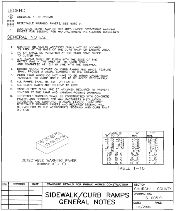
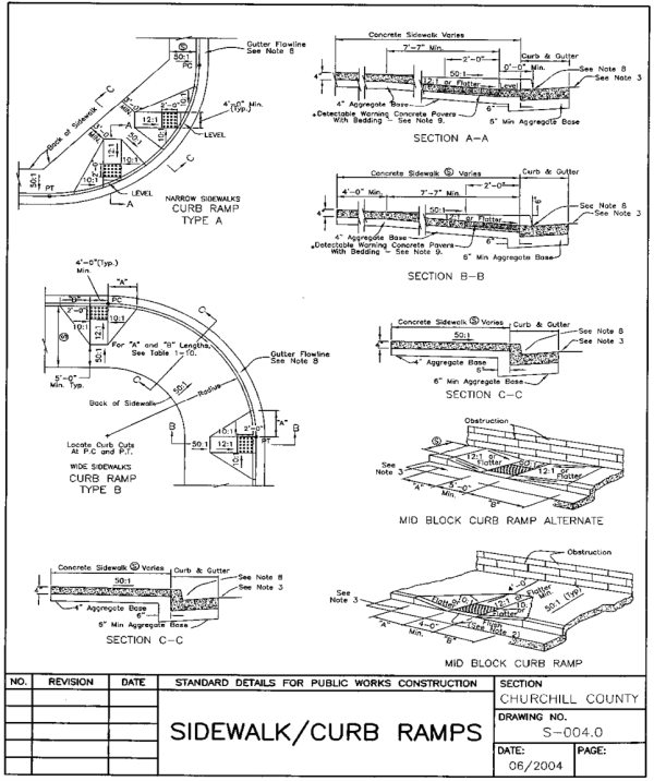
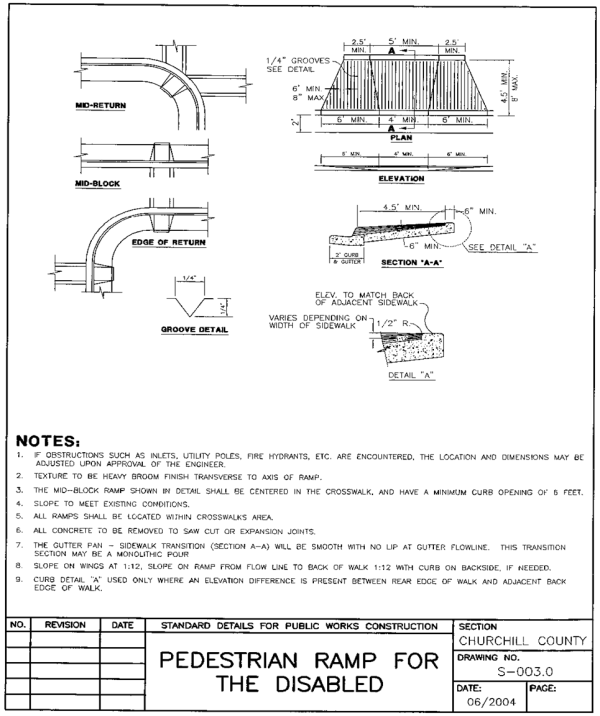
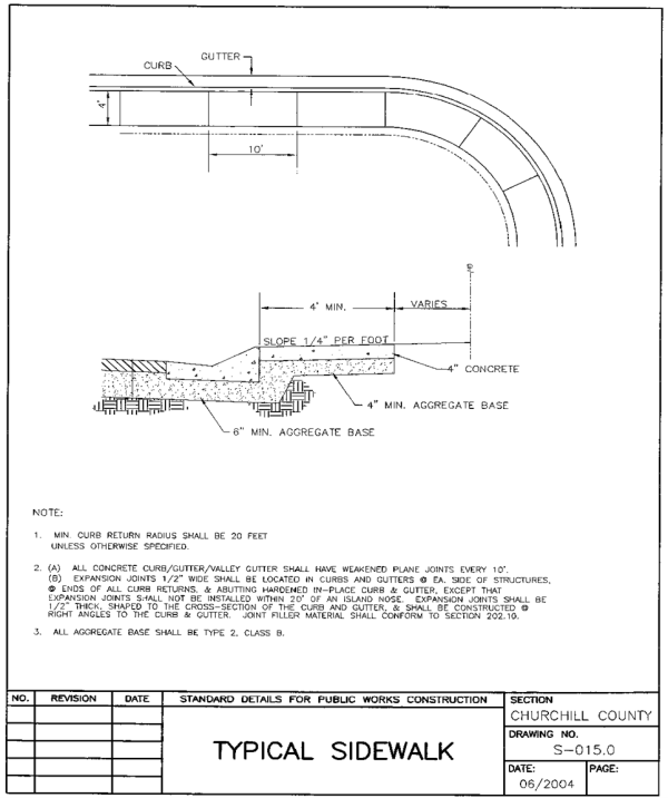
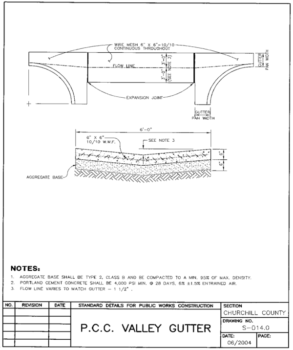
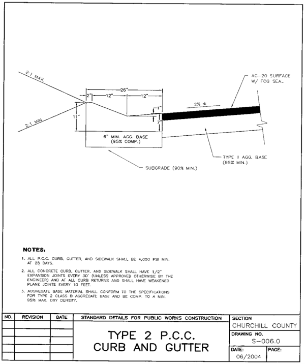
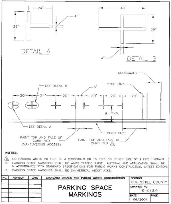
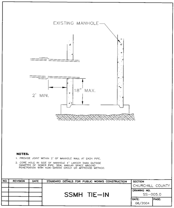
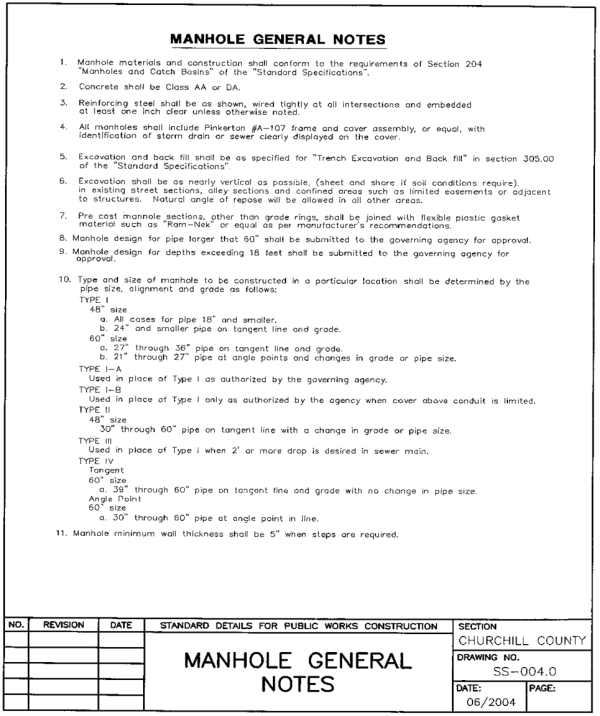
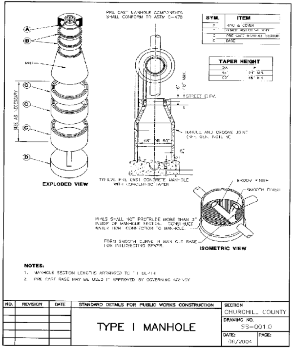
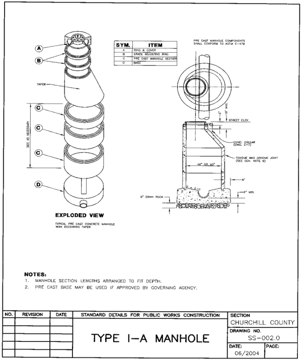

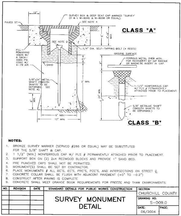
All other illustrations may be reviewed at the Churchill County road department.
(Bill No. 2012-F, 2012)
Bill 2025-A, Ordinance 32
16.16.010.1 Easements
- Legal and physical access shall be established prior to any development. A minimum 30-foot-wide legal easement and a 20-foot-wide traveled way built to fire code standards, with an unobstructed width of 20-feet and a surface to provide all weather driving capabilities from the property to a public right of way must be provided for the construction of any primary structure. Where a bridge is included as access to a parcel, it must be constructed with a minimum width of 20 feet. Where an existing bridge is to be utilized as access, evidence must be provided from a professional engineer licensed in the state of Nevada that the bridge is structurally sound. Adequacy of the bridge for use by emergency vehicles shall be at the discretion of the fire marshal.
A minimum 60-foot-wide legal easement with roads and bridges constructed to this Code's and "Orange Book" standards is required for any land division. - The developer shall grant easements not less than a total of ten feet in width for public utility, sanitary sewer and drainage, and other public purposes on yard or open areas wherever necessary. Easements of lesser widths may be allowed when the purposes of same may be accomplished by lesser widths; provided further, that in such determination the planning commission shall prescribe the width of such easements. Overlapping of easements should be avoided if possible.
- All natural drainageways and irrigation waterways and drainageways shall be preserved with appropriate easements and/or pedestrian walkways where necessary and required by the planning commission.
- A conservation easement of a width to be determined by stream flow requirements shall be provided along all waterways and streams and rivers to contain the channel during flood stages and to maintain the ecological integrity of the watercourse and to prevent encroachment. This easement need not be open to public access, but no tree or brush removal, gravel excavation, filling or side casting of materials shall be allowed within the area and no construction of any kind shall be allowed.
- In areas of possible fire hazards, unobstructed fire protection equipment and access easements not less than 20 feet shall be dedicated from the public street to the land development boundary. Such easement shall be located, designed and graded as determined by the planning commission in cooperation with the fire protection agencies.
(Bill No. 2005-F § 2.2, 2005; Bill No. 2007-I, 2007)
16.16.010.2 Grading And Drainage
New development including proposed subdivisions, second and subsequent parceling, and building sites over one acre in size shall provide adequate plans depicting proposed grading of site and proposed storm drainage improvements. Submitted information shall address the following:
- A geotechnical report, a drainage report, and a grading plan shall be required with submittal of improvement plans for subdivisions and parceling. A drainage report and grading plan shall be submitted with the building permit application for building sites.
- All grading requirements shall be as set forth under this title.
- All cleared slopes, all cuts and fills, and all other areas vulnerable to erosion shall be either stabilized with grass or other protective cover or properly mulched to assure establishment, riprapped for slope control, treated with a soil solidifier or be provided with appropriate drainage benches as may be determined by the building official or county engineer. On steep slopes it may be required to provide controls as necessary to the circumstance.
- The developer shall design the development so that it is protected from inundation, flood hazard, sheet overflow, and ponding of local stormwater, springs and other surface waters.
- The design of improvements shall be such that water occurring within the development will be carried off without injury to any improvements, building sites or residences to be installed on sites within the development or adjoining areas.
- Waters occurring within the development shall be carried to a storm drainage facility or to a natural watercourse by such improvements as may be required.
- Drainage design within the development shall accommodate reasonable anticipated future improvement within the drainage area.
- Any off-tract outlets drainage facility required to carry stormwater from the proposed development to a defined channel or conduit shall be made adequate for the ultimate stage of improvement in the drainage area.
- All water shall be discharged into a controlled outlet stabilized storm channel for erosion control.
- All such off-site drainage water shall be materially free of silt or other polluting features.
(Bill No. 2005-F § 2.2, 2005; Bill No. 2007-I, 2007)
16.16.010.3 Land Dedication
Dedications of land for park, recreation, school or other public purposes, in an amount and location consistent with the master plan and proposed character and location and engineering need of each development, may be required as condition precedent to tentative and final plat approval.
(Bill No. 2005-F § 2.2, 2005)
16.16.010.4 Land Clearing Restrictions
At the time of the tentative plat approval, the planning commission may impose, as a condition of such approval, restrictions on the making of improvements consisting of the clearing of brush and trees or of the moving of earth by mechanical equipment. Such restrictions may include a provision that no such improvements may be made for a given period of time, including the time up to the filing of the final map. In order to impose any of the restrictions authorized by this section, there shall be a determination by the planning commission that such improvements would result in a real danger of the following:
- Pollution, contamination or silting of lakes, rivers, streams of domestic water supplies, irrigation waterways; or
- Erosion damage; or
- Alteration of natural drainage patterns in a manner likely to cause damage to the property or persons from which the normal drainage is diverted.
(Bill No. 2005-F § 2.2, 2005)
16.16.010.5 Preservation Of Native Features And Topsoil
Healthy trees, rock outcrops, and other native features shall be preserved whenever possible and shall be protected during periods of construction. All native growths within the area to be divided will be surveyed for weakness, maturity, decadence, potential hazard, infestation, vigor, density, spacing and type. A preservation and protection plan will be made a part of the tentative plat with an indication thereon of those growths proposed to be removed, those to remain, and where new elements are to be planted. Clearing of topsoil, trees and shrubs, and other native cover prior to site development approval is prohibited. Topsoil shall be removed from building sites, parking areas, driveways, etc., and stored for future use when required by the county engineer. The location of native features shall be considered when designing building sites, underground services, walkways, paved or parking areas, playgrounds and especially finished grade levels.
(Bill No. 2005-F § 2.2, 2005)
16.16.010.6 Common Areas
Where deemed desirable by the planning commission, upon consideration of the particular type of improvement proposed in the development, and especially in large scale neighborhood unit developments, the planning commission may require dedication or reservation of common areas or sites for community purposes of a character, extent and location suitable for the needs created by such development.
- Scenic values; existing flora; other facilities.
- The planning commission may require other such measures as will preserve and enhance scenic values and natural features of the area and for conditions encouraging excellence of quality of development.
- Existing flora shall be preserved within any public way when such growths are suitably located and healthy and when approved grading permits. When required, street trees shall be planted in accordance with the requirements of the planning commission.
- The developer may be required to provide necessary irrigation facilities and structures such as bridges, concrete boxes, culverts, head walls, cattle guards, appurtenant fencing and other features as stipulated by the planning commission and county engineer.
(Bill No. 2005-F § 2.2, 2005)
16.16.010.7 Streets And Storm Drains
- General provisions. Design standards and specifications for streets and storm drains are adopted by the board of county commissioners and amended as necessary. The Churchill County road department and planning department, hereinafter referred to as "county", will review all developments located within the Churchill County boundaries to evaluate the feasibility of integrating the development, presently or in the future, with Churchill County systems. Developers and their consulting engineers must meet with the county prior to any formal plan submittal to discuss proposed street design, alignment and layout to ensure compliance with the master plan and transportation plan, compliance with development standards and the feasibility of integration into existing and future systems. Once a project has been determined feasible, complete design and improvement plans are required for county review.
- Legal compliance. The developer and the engineer shall comply with all applicable federal and state laws, county ordinances, the Americans with Disabilities Act and regulations that affect the design of water, alternative water, wastewater systems, storm drainage and street improvements.
- Agency approvals. It is the responsibility of the developer and/or engineer of record to obtain the approvals of any required public agency prior to submitting improvement plans to Churchill County for approval, as the county will require copies of all permits, approvals, correspondence and/or requirements from other agencies directly associated with the development.
Churchill County requires written notice of approval by the appropriate review agency. The planning department of Churchill County may require a special use permit (SUP) for aboveground structures such as tanks and pump station buildings. The engineer of record must verify such requirements. - Approved plans. Complete designs for storm drainage and street improvements, including any necessary dedications, easements, and rights of way, shall be submitted to and approved by Churchill County prior to the start of the project or final subdivision map being approved.
- Facilities and public land. All Churchill County facilities shall be either on or within land owned by Churchill County, or within public easements.
- Improvement plans.
- Plans by engineer. All plans, specifications, calculations, reports, easements, and rights of way submitted to Churchill County shall be prepared, stamped, and signed by the engineer of record in accordance with NRS tit. 54, ch. 625. All submittals must be wet stamped by a civil engineer registered in the state of Nevada. Any improvement plans submitted to Churchill County that are not stamped by a civil engineer registered in the state of Nevada will be cause for rejection and resubmittal.
- Improvement plan submittal. The initial submittal of improvement plans to Churchill County shall consist of the following:
- Three sets of blue line or black line (OCE) plans, complete and in accordance with these review guidelines, along with any required specifications, computations, test data, reports, studies, analysis and other material requested by the county, including two copies of a geotechnical report, three copies of a drainage report, and a phasing plan and paving schedule, if applicable. Site plans and utility plans shall be prepared in a format compatible with Churchill County GIS data for integration with the GIS system. Churchill County uses the North American Datum, 1983 (NAD 83) Nevada State Plane, west zone (2703), U.S. Survey Foot Projection. Vertical datum shall be North American Vertical Datum, 1988 (NAVD 88).
- The name, address and telephone number of the owner and the engineer of record to be contacted concerning the plans.
Churchill County will review the plans within 30 calendar days of receipt. If alterations or revisions are required to the plans as submitted, the county will return one redlined improvement plan set with the corrections marked or indicated. If the improvement plans submitted are not prepared in accordance with these review guidelines or in keeping with the standards of the profession, Churchill County may return them unmarked and unapproved. Churchill County will not, under any circumstances, provide design by review. It is the engineer of record's responsibility to ensure proper engineering principles are incorporated in each design. - The county engineer, or designee, is required to sign the cover sheet of all submittals.
- Improvement plan resubmittal. Plans being resubmitted shall consist of a minimum of three complete sets of plans and the returned redlined markup. Additional sets may be required by Churchill County. Plans being resubmitted that contain revisions or alterations other than those required by the county shall be identified as to the revisions made, and will be treated as an initial submittal.
- Approved plans. Once the improvement plans have been approved by the county, a signed set of approved plans will then be returned by the county to the engineer of record. All other pertinent review/approval agencies must provide authorization (signatures) prior to submitting to Churchill County for approval. Once all signatures are obtained (including, but not limited to, the Churchill County road department and Churchill County planning department), two sets of approved plans will be retained by the county. Improvement plans shall be approved by Churchill County before construction begins. All construction shall be in accordance with the approved plans. Any required revisions to the approved plans shall be submitted by the engineer of record and approved by Churchill County prior to construction.
- Project inspection. Inspection of infrastructure within Churchill County rights of way will be performed by Churchill County or its authorized agent and all costs incurred will be paid by the owner/developer. Prior to construction, one percent of the engineer's estimate for the total project will be deposited with the road department for inspections. All other required materials testing and special inspections shall be performed in accordance with "orange book" guidelines by an independent inspection/quality control entity, which the owner/developer is responsible for securing and all costs incurred will be paid by the owner/developer. The owner/developer shall provide Churchill County with the materials testing firm and/or special inspector contact information in writing. Churchill County reserves the right to inspect the project at any time and to require replacement of the materials testing firm and special inspector used. The county or its authorized agent shall have the authority to approve field changes and shut down projects should this action be necessary in the best interest of the county. Reports of all materials testing and special inspections provided by the owner/developer shall be submitted to Churchill County prior to each phase of construction and a complete summary report shall be provided at the end of construction.
- Bonding requirements. All development projects are required to be bonded prior to project commencement unless the final map is to be filed after completion and acceptance of the improvements. The bond shall be based on a county approved engineer's estimate that includes a ten percent contingency of the project cost. The owner/developer shall be required to post a surety bond, cash or improvement security with Churchill County to guarantee the satisfactory completion of any improvements to county systems. The total bond amount shall be for 110 percent of the total estimated cost that includes contingency. The owner/developer shall enter into a performance agreement with the county when the bond is posted, said agreement to be approved by the county prior to construction.
- Preconstruction meeting. A preconstruction meeting will be conducted by the developer prior to project commencement. A representative of Churchill County, the contractor, testing firm and engineer of record/independent inspector is required to be present at the preconstruction meeting. The developer must schedule the preconstruction meeting and shall provide at least one-week prior notice to the county of the date and time of the meeting. Upon completion of the preconstruction meeting, a notice to proceed will be issued by Churchill County.
- Revisions after approval. Should revisions to the approved plans become necessary, the engineer of record shall submit two sets of plans showing the proposed revisions. Once the plans are approved by Churchill County, one set will be returned to the engineer of record. Major project changes or revisions require approval by the county prior to incorporating the change in the field. Any major revisions to the project that are not approved by the county prior to implementation shall result in removal of the work associated with the change and replacement. All removal and replacement work required shall be at the developer's expense.
- Conflicts, errors and omissions. Excepted from approval are any features of the plans that are contrary to, in conflict with, or do not conform to Nevada state law, this title or resolution, Churchill County standards, conditions of approval, or generally accepted good engineering practice in keeping with the standards of the profession, even though such error, omissions or conflicts may have been overlooked in Churchill County's review of the plans.
- Partial plans. Where the improvement plans submitted cover only a portion of the ultimate development, the plans submitted shall be accompanied by the approved tentative plans for the entire project. Where no approved tentative plan exists, a conceptual project plan that adequately shows project improvements, topography, and other pertinent features shall be submitted. All phased boundaries shall be clearly identified on the plans.
- Plan sheet requirements. All improvement plans shall be on sheets measuring 24 inches by 36 inches or 22 inches by 34 inches. Upon approval, one set of reduced "1/2 scale" plans shall also be provided to the county on 11 inch by 17-inch size sheets. All street, storm drain, water and sewer improvement plans require plan and profile for proposed and existing conditions unless waived by Churchill County. Plan and profile sheets shall have a horizontal scale of one-inch equals 20 feet, 40 feet, or 50 feet; and a vertical scale of one-inch equals two feet, four feet, five feet or ten feet. Each sheet shall be drafted in a neat and legible manner. Every professional consideration shall be given to these plans. All improvement plans shall have a title sheet containing the following information:
- Project name.
- Name, address and telephone number of the owner, developer and engineer of record.
- Location map.
- Legal description.
- Parcel numbers.
- List of quantities of all Churchill County system improvements (an affidavit stating that the quantities are not to be used by the contractor for purchasing is acceptable).
- Index of sheets.
- Abbreviations.
- Legend of symbols.
- Signature lines for Churchill County planning department, Churchill County road department, and Truckee-Carson Irrigation District (if applicable due to the proximity of their easements or facilities) approval and any other entity approvals requested by the planning director.
- General notes.
- Each sheet within the set of drawings shall have a title block showing the sheet title, page number, date, scale and the engineer's name, signature and stamp.
- The stationing on plan and profile sheets shall read from left to right. Plans shall be arranged with the north arrow pointing toward the top or upper portion of the sheet, insofar as practical. Bench marks and datum shall be clearly identified on the plans as to location, description, and elevations. Churchill County will not act as the engineer's quality control.
- All grading plans shall conform to the approved hydrology study and indicate as such on the plans.
- Standard details. All roads and bridges are to be constructed to Churchill County specifications in accordance with "standard specifications for public works construction" ("orange book") distributed by the regional transportation commission. All specifications and standard details are to be obtained through the Churchill County road department. All roads and bridges are to be inspected and approved by the Churchill County road department.
- As built drawings. Upon completion of construction and prior to acceptance of the work, the engineer of record shall submit one blue line or black line hard copy and an electronic copy (a scanned copy is required if the revisions are hand drawn) of as built drawings.
The engineer of record shall provide an as built survey of all utilities and infrastructure within the county right of way. The survey shall be on the NAD 83 Nevada west zone (2703) horizontal datum and NAVD 88 vertical datum. The specific ground to grid factor shall also be provided to allow for integration into the county's GIS database. The survey will include, but not be limited to, water valves, meters, hydrants, manholes, sewer lateral stubs, drop inlets, and centerline monuments. All manholes and drop inlets shall be measured and documented on manhole data forms to verify invert elevations and pipe sizes.
All modifications to the original design shall be clouded on the pertinent sheet and clearly marked and noted in the revision block of that plan sheet. Major revisions shall constitute reprinting of the revised plan. Minor revisions may be hand rendered, clouded, and recorded in the revision block on the plans.
As built drawings must be submitted to Churchill County within 20 days of the construction completion date.
The as built drawings shall be a print of the modified construction plans and shall be identified as "as built drawings" on all sheets. - Naming of existing roads.
- Road names and suffixes shall be designated by the developer, subject to approval of the planning department and in accordance with the following general policy:
- Be short (under 12 letters if possible) and preferably in one word;
- Have a simple spelling and easy pronunciation;
- Avoid prefixes such as "north" and "south", "east" and "west", "upper" and "lower";
- Be related to the type and importance of the street (e.g., the suffix "boulevard" should not be attached to the name of a minor residential street);
- Avoid the use of numbers or letters as street names;
- Not be incongruous, offensive or geographically misleading;
- Not be repetitive or similar in sound and character;
- Have a single name for a street having a continuous alignment;
- When to be connected in the future into a continuous alignment, or extended, bear the same name as the existing street;
- An existing noncounty maintained road may be named or renamed using the following procedure:
- A landowner fronting the road submits a road name application according to the provisions above using the approved road name application. The application must be complete with three different road names and a list of all other landowners that will be affected.
- If postmaster, sheriff's office/fire marshal and all landowners agree to the road name, the name is approved by planning department. It is the responsibility of the landowners to provide and maintain street signs and stop signs for roads not maintained by the county.
- Road names and suffixes shall be designated by the developer, subject to approval of the planning department and in accordance with the following general policy:
- Street design standards.
- General provisions.
- Unless otherwise specified by Churchill County adopted standards, standard specifications and details for Churchill County construction or items in this chapter, design of all streets and related improvements shall conform to the following: Churchill County specifications in accordance with "standard specifications for public works construction" ("orange book") distributed by the regional transportation commission and "manual for uniform traffic control devices" published by Federal Highway Administration and U.S. Department of Transportation. The more restrictive standard shall prevail for design. All specifications and standard details are to be obtained through the Churchill County road department. All streets are to be inspected and approved by the Churchill County road department.
- Street widths, lengths and alignments shall generally conform to these review guidelines and the standard details for Churchill County construction and elements thereof. All streets and alleys within a subdivision or development shall be improved and conform to Churchill County standards and shall be constructed in phases/sections no less than 500 feet in length unless specifically authorized by the county road department. Additional right of way shall be provided near intersections as required by the county in order to facilitate turning movements and ADA accessibility.
- Rural paved residential streets shall be constructed on a minimum road easement 60 feet in width. The paved section shall be 26 feet in width with a minimum of four feet wide compacted shoulders. Shoulders will be constructed to facilitate stormwater runoff. Curb and gutters may be required to ensure proper drainage of stormwater runoff, as determined by the road department.
- Grade gravel residential streets shall be constructed on a minimum road easement 60 feet in width. The traveled way will be a minimum of 34 feet in width and shoulders will be constructed to facilitate stormwater runoff.
- Street design shall conform to standard details and be based on the design subgrade resilience modulus (R-value) provided in a soils (geotechnical) report prepared by a Nevada registered civil engineer, submitted with the improvement plans. All soils report recommendations are to be incorporated into the design of the improvements. A drainage report, prepared by a Nevada registered civil engineer, shall also be submitted with the improvement plans.
- All boring and test pit logs shall be shown on the plans. Where groundwater is encountered, the elevation of groundwater shall be indicated in all profiles.
- Design standards. The "standard specifications for public works construction", latest edition ("orange book"), and "Churchill County design standards and review guidelines for streets and storm drains" have been adopted by the board of county commissioners of Churchill County and represent the minimum design and construction criteria. All design, construction and maintenance of streets and storm drains conducted or made within Churchill County, Nevada, shall conform to the adopted standards. The Churchill County road department is and shall be authorized to establish, promulgate and revise as necessary, design, construction and maintenance standards relating to streets and storm drains within Churchill County, Nevada. The most recent version of such standards shall be available at the road department.
- Road maintenance. The developer shall enter into an agreement with the county, said agreement to be approved by the district attorney's office guaranteeing all work performed for a period of one year. The developer shall repair at his sole expense any defects in workmanship or material which appear in the work within one year of an inspection and approval by an appointed county authority. The developer shall also post a security for ten percent of the total engineer's estimate for each phase of road construction for repair and maintenance during the one-year period should the developer not make the repairs. The agreement shall state that any repair work required within one year from the time of inspection shall cause an additional minimum of one year time period of guarantee by the developer. The county highway commission shall, at the road department's request, cause roads that have been constructed to this Code's and "orange book" standards for paved roads to be expressly accepted by the county and placed on a continuing county maintenance schedule; at no time shall the county consider acceptance of gravel roads for maintenance.
- Minimum access roads.
- Criteria. The minimum access road is the absolute minimum in regard to road specifications for parceling purposes. Parcel splits not meeting the specific criteria for a minimum access road will be subject to road requirements currently specified in this Code. A variance cannot be granted from the specifications of a minimum access road. All of the following criteria must be met to qualify for a minimum access road:
- Subject property to be divided must abut a publicly maintained road and the minimum access road to be provided shall not exceed 750 feet in length.
- Second and subsequent parceling maps must comply with road requirements specified in this Code and are not eligible for minimum access roads.
- The property cannot be zoned for commercial or industrial use.
- Minimum specifications. Minimum specifications for a minimum access road:
- Road shall have an unobstructed width of not less than 20 feet and the Fallon/Churchill fire marshal shall have the authority to require an increase in the width where determined inadequate for fire or rescue operations.
- Road shall be designed and maintained to support a minimum 35-ton load and shall be surfaced to provide year-round, all weather driving capability for emergency vehicles.
- An adequate approved turnaround per the International Fire Code, latest edition, or approved by the Fallon/Churchill fire marshal shall be provided.
- A minimum 30-foot unencumbered road easement to the last parcel created shall be provided if there is no potential for development of immediate or abutting properties.
- A 60-foot unencumbered road easement through the last parcel shall be provided if there is potential for development of adjoining properties or properties in the immediate vicinity that utilize the existing road easements to the subject property.
- Road shall not be named.
- Any upgrades required by the fire marshal shall initially be the responsibility of the party requesting the land division. All further upgrades, maintenance, and repairs shall be the responsibility of each landowner.
- All addresses must be permanently and clearly posted at the entrance to the minimum access road and at the entrance to each property.
- Bridges and culverts.
- On a 60-foot easement, a 34-foot standard crossing (bridge/culvert) is required at surface or traveled way.
- On a 30-foot easement, a 30-foot crossing (bridge/culvert) is required at surface or traveled way.
- Maintenance.
- Original developer must enter into and sign a minimum access road maintenance document that includes the development name and owner name. The document will be signed and recorded by Churchill County.
- Each property owner is solely responsible for the repair and maintenance of the roadway and road easement located on his/her property. Maintenance or repair of roadway, road easement or crossing shall not be the responsibility of Churchill County.
- Criteria. The minimum access road is the absolute minimum in regard to road specifications for parceling purposes. Parcel splits not meeting the specific criteria for a minimum access road will be subject to road requirements currently specified in this Code. A variance cannot be granted from the specifications of a minimum access road. All of the following criteria must be met to qualify for a minimum access road:
- General provisions.
- Stormwater drainage. "Churchill County design standards and review guidelines for streets and storm drains" has been adopted by the board of Churchill County and represents the minimum design and construction criteria. All design, construction and maintenance of storm drains conducted or made within Churchill County, Nevada, shall conform to the adopted standards. Churchill County is and shall be authorized to establish, promulgate and revise as necessary, design, construction and maintenance standards relating to storm drains within Churchill County, Nevada. The most recent version of such standards shall be available at the road department.
(Bill No. 2005-F § 2.2, 2005; Bill No. 2006-G, 2006; Bill No. 2007-I, 2007; Bill No. 2010-G, 2010)
16.16.010.8 Traffic Impact Study
- Purpose. Traffic studies are required by Churchill County to adequately assess the impact of a proposed development on the existing and/or planned highway system. The developer will have the primary responsibility for assessing the traffic impacts associated with a proposed development, with the county serving in a review and approval capacity.
- Traffic impact study requirements.
- Developments that generate 80 or more peak hour weekday trips or 500 average daily traffic (ADT) as determined by the current edition of the Institute of Transportation Engineers (ITE) "Trip Generation Manual".
- Developments that generate less than 80 peak hour weekday trips or 500 average daily traffic (ADT) and deemed to have impacts to safety, the neighborhood, intersection capacity, high accident areas, traffic circulation, or other concerns identified by the county or NDOT.
- Phased developments that generate over 80 peak hour weekday trips or 500 average daily traffic (ADT) when including traffic from all phases, or at the discretion of the county.
- General provisions.
- The traffic engineering consultant is required to contact the county to define and obtain approval of the traffic study area limits.
- The traffic study will be the responsibility of the applicant and must be prepared and sealed by a Nevada licensed engineer who has expertise in traffic studies and transportation planning.
- Upon receipt of a draft traffic study, the county engineer and road department will review the study data (sources, methods and findings) and will respond with written comments. The developer and engineer will then have an opportunity to incorporate necessary revisions prior to submitting a final report. The county engineer then must approve the final report before an application will be accepted.
- All previous traffic studies that are more than two years old at the time that construction commences on the project will require updating. This may be waived if conditions have not significantly changed.
- Traffic counts that are over one year old cannot be used in the traffic study, unless prior approval is given by the county.
- The county must approve the development's trip generation, trip distribution, pass-by rates, internal capture rates, and the methods used to establish a buildout condition, prior to the traffic study submittal.
- In the case of jurisdictional overlap, the applicant's traffic engineering consultant should meet with other appropriate jurisdictions, such as NDOT, to define the scope of the project. The applicant will have to satisfy the requirements of all jurisdictions involved in reviewing the traffic study.
- Traffic study report format. The following format represents the minimum information to be included in the traffic impact study.
- Executive summary. This will contain a brief project description and concise description of the study findings.
- Introduction.
- Project description.
- Site location.
- Study area boundaries.
- Existing conditions.
- Adjacent and study roadway description: Describe study roadways including noting bus routes, bike lanes, on street parking, functional class, jurisdiction, shoulder types, median type, speed limits, etc.
- Study intersection description: Describe study intersections including control type, pedestrian control, jurisdiction, etc.
- Current zoning: Call out the existing zoning of the project and adjacent parcels.
- Existing intersection volumes (peak hour): Show the existing peak hour traffic count volumes at study intersections.
- Existing roadway volumes (daily volumes): Show the existing daily traffic volumes, if available, at study road segments.
- Existing intersection and roadway level of service:
- Perform intersection and roadway level of service analyses as found in the most current version of the "Highway Capacity Manual".
- State or show the existing vehicle queue lengths at study intersections or driveways.
- Existing accident data: High accident intersections or road segments should be noted when accident data is available. The cause of these high accident locations should also be investigated and included in the report, when accident data is available.
- Site plan analysis.
- Site plan:
- Provide a scaled drawing of the site plan as analyzed in this traffic study. Include building and parking locations and note on the site plan the land uses of adjacent parcels.
- Access spacing:
- The current county access spacing standards should be followed or, with county approval, consult AASHTO's "a policy on geometric design of highways and streets".
- Show the location of project driveways and all other accesses both adjacent to and on the opposite side of the roadway.
- Clearly identify secondary or emergency accesses and state if they are gated, unrestricted, shared by other properties, and are temporary. Approval from the fire department is required.
- Traffic circulation:
- Review the site plan for general traffic circulation such as on-site vehicle queuing and ease of access.
- Access points expected to be used by service vehicles shall have turning paths sufficient to allow service vehicles to enter and exit the site without encroaching upon opposing lanes, curbed areas or unpaved areas.
- Pedestrian circulation:
- Review the site plan for pedestrian flow, adequacy, and safety.
- Site plan:
- Project conditions.
- Project vehicle trip generation.
- Project vehicle trips shall be estimated using the methodologies found in the most current version of the following Institute of Transportation Engineers (ITE) publications:
"Trip Generation Manual" — estimating project vehicle trips.
"Trip Generation Handbook" — estimating pass-by and internal trips.
ITE articles and other publications — estimating trips for nontypical projects. - The county may require specific trip generation rates to be used in specific cases that differ from the ITE average values when the results of local studies differ from the national values. If ITE values are not available for the proposed land use, a local trip generation study may be performed at comparable land uses.
- Trip generation should include the following:
Average daily traffic (ADT).
A.M. peak hour trips (in and out).
P.M. peak hour trips (in and out).
Pass-by or diverted trips if applicable (when applicable).
Internal capture rates for large multi-use projects. - The county must approve the project trip generation prior to submittal of the traffic study.
- Project vehicle trips shall be estimated using the methodologies found in the most current version of the following Institute of Transportation Engineers (ITE) publications:
- Trip distribution and assignment.
- Project traffic is to be distributed to the road network based on existing traffic counts, proximity to major roadways, and engineering judgment. Project traffic is to be shown separate from background and other traffic.
- The county must approve the project trip distribution before submittal of the traffic study.
- Project vehicle trip generation.
- Existing plus project conditions. Combine the existing background traffic with the estimated project traffic and perform a traffic impact and capacity analysis of the site traffic on the existing road network.
- Existing plus project intersection volumes (peak hour):
- Show the combined existing plus project peak hour traffic volumes at study intersections.
- Existing plus project roadway volumes (daily volumes):
- Show the combined existing plus project daily traffic volumes at study road segments.
- All roadways must maintain level of service per the direction of the most current version of the county's adopted long range transportation plan. Currently, LOS C or better is acceptable.
- Existing plus project intersection and roadway level of service:
- Perform a combined existing plus project intersection and roadway level of service analysis as found in the most current version of the "Highway Capacity Manual".
- State or show the estimated changes in queue lengths when adding project traffic to existing traffic queue lengths at the study intersections or driveways.
- All intersections must maintain a level of service per the direction in the most current version of the county's adopted long range transportation plan. Currently, LOS C or better is acceptable.
- Existing plus project intersection volumes (peak hour):
- Existing plus project with mitigation.
- When intersections or roadways fall below an LOS C, mitigation measures are to be analyzed and presented here.
- Other mitigation measures such as unacceptable vehicle queues and poor circulation are to be presented here.
- When signalization is required to mitigate project traffic effects, a signal warrant analysis needs to be provided. The methodologies for signal warrants found in the "Manual on Uniform Traffic Control Devices" (MUTCD) are to be used.
- Buildout condition.
- This scenario is to represent the project at full buildout including background traffic growth over the life of the project.
- Level of service analyses are to be performed and presented here as in previous sections of the report.
- Cumulative/future condition.
- This scenario is to represent a 20-year horizon and help in determining how the proposed projects fit into the long-range planning efforts of the county. Traffic volumes for this condition can be estimated using long range transportation models, NDOT growth projections, growth factors, or a travel demand model. It is recommended to consult the county to determine available data and acceptable methodologies.
- Include road or other infrastructure projects that are approved or planned as detailed in Churchill County's long range transportation planning documents.
- Show road segment level of service or capacity levels as detailed in the most current Churchill County transportation plan or other jurisdictions' documents.
- Conclusions/recommendations.
- All conclusions and recommendations are to be detailed here in a clear and concise format. Figures may be included to show recommended improvements or mitigations.
- Appendices.
- All raw traffic count data, including hourly, average daily traffic (ADT), turning movements, and peak hour counts, and analysis worksheets shall be provided in appendices. Traffic analysis computer programs and printouts may be used as part of the report.
- Figures can be included within each of their respective sections or included in the front of the appendix.
(Bill No. 2005-F § 2.2, 2005; Bill No. 2018-E, 2019)
16.16.010.9 Water And Wastewater Facility Standards
- Introduction. The Churchill County board of county commissioners adopted ordinance 32. This ordinance, as amended, requires that all new sanitary sewer facilities, water facilities, and appropriate water rights in the unincorporated area of Churchill County which are not appurtenant to an existing public service commission certificated utility company shall be dedicated to Churchill County. The engineering department or an authorized representative is charged with review of the design and improvement plans for these facilities to be dedicated.
This document is meant to assist the consulting engineer with the preparation of the required design and improvement plans. It is impossible to cover all contingencies and possible situations within a single document. Conditions and situations not covered in these standards and guidelines shall be designed in accordance with standard engineering practice and as approved by the engineering department or an authorized representative. - Compliance with laws. The developer and the engineer shall comply with all applicable federal and state laws, county ordinances, and regulations which affect the design of water and sanitary sewer systems.
- Agency approvals.
- It is the responsibility of the developer and/or engineer to acquire the approvals of any required public agency prior to submitting improvement plans to the engineering department or authorized representative for approval. Agencies which may be involved in approval of water and wastewater sewer plans include:
- Local public utilities — Churchill County.
- Nevada Division of Environmental Protection (NDEP).
- Nevada Division of Environmental Protection (NDEP), bureau of safe drinking water (BSDW).
- Churchill County fire marshal.
- Truckee-Carson Irrigation District (TCID).
- Bureau of reclamation (BOR).
- Nevada Division of Water Resources (NDWR).
- Nevada Department of Transportation (NDOT).
- It is the responsibility of the developer and/or engineer to acquire the approvals of any required public agency prior to submitting improvement plans to the engineering department or authorized representative for approval. Agencies which may be involved in approval of water and wastewater sewer plans include:
- Approved plans. Complete designs and plans for water and wastewater systems, including any necessary dedications, easements, and rights-of-way, shall be submitted to and approved by the engineering department prior to the final subdivision or parcel map being submitted for action by the board of county commissioners. Plans shall reflect energy efficient facilities.
- Abbreviations. Wherever the following abbreviations are used, the intent and meaning shall be as follows:
APWA - American Public Works Association ASCE - American Society of Civil Engineers ASTM - American Society for Testing and Materials AWWA - American Water Works Association CCC - Churchill County Board of County Commissioners IBC - International Building Code IECC - International Energy Conservation Code IFC - International Fire Code IFGC - International Fuel Gas Code IMC - International Mechanical Code IPC - International Plumbing Code IRC - International Residential Code NAC - Nevada Administrative Code NEC - National Electrical Code NRS - Nevada Revised Statutes OSHA - Occupational Safety and Health Administration SDWA - Safe Drinking Water Act - Facilities and public land. All pipelines shall be on or within land owned by Churchill County or public easements. All water tanks, wells, pumping facilities, or structures to be dedicated to the county shall be on land owned by the county.
- Improvement plans.
- Plans by engineer of record. All plans, specifications, calculations, easements, and rights of way submitted to the engineering department shall be prepared, stamped, and signed by the engineer in accordance with NRS ch. 625. All submittals may be either wet stamped or copies of stamped originals.
- Improvement plans submittal. The initial submittal of improvement plans to the engineering department shall consist of the following:
- Three sets of blue line plans, complete and in accordance with these guidelines, along with any required specifications, computations, test data, and other material requested by the engineering department.
- The name, address, and telephone number of the person to be contacted concerning the plans.
- Improvement plan resubmittal. Plans being resubmitted shall consist of three complete sets of plans. Additional sets may be required by the engineering department. Plans being resubmitted that contain revisions or alterations other than those required by the engineering department shall be identified as to the revisions made, and will be treated as an initial submittal. Per NRS ch. 625, the county will not perform design by review. The engineer of record is responsible for using sound engineering principles in design.
- Approved plans. Improvement plans meeting approval shall be stamped "approved" and signed by an authorized representative of the engineering department. One set of approved plans will be returned and two sets of approved plans will be retained by the engineering department. One set of retained plans will be kept on file in the planning department and the second set will be used by the engineering department and/or the authorized representative charged with inspection. Improvement plans shall be approved by the engineering department. Before the final subdivision map or parcel map is signed by the planning commission, the infrastructure must be inspected and approved, or a bond filed as per the requirements of this chapter. Approval of the improvement plans is valid only while the final map is in good standing. Approved plans shall be required prior to the final map being placed on the agenda for action by the board of county commissioners.
All construction shall be in accordance with the approved plans. Any required revisions to the approved plans shall be submitted by the design engineer and approved by the engineering department prior to construction. Inspection is being provided by the engineering department's authorized representative and the design engineer is required to certify that construction is in accordance with the plans. - Revisions after approval. Should revisions to the approved plans become necessary, the engineer shall submit three sets of plans showing the proposed revisions. If the revisions are approved by the engineering department, one set of approved plans will be returned to the engineer.
- Conflicts, errors and omissions. Excepted from approval are any features of the plans that are contrary to, in conflict with, or do not conform to Nevada state law, Churchill County Code or resolution, conditions of approval, or generally accepted good engineering practice in keeping with the standards of the profession, even though such errors, omissions or conflicts may have been overlooked in the engineering or other department's review of the plans.
- Partial plans. Where the improvement plans submitted cover only a portion of the ultimate development, the plans submitted shall be accompanied by the approved tentative plans for the entire project. Where no approved tentative plan exists, a conceptual project plan which adequately shows project improvements, topography, and other pertinent features shall be submitted. Phased projects shall clearly define limits of each phase. All system components shall be sized and calculated for the complete development.
- Plan sheet requirements. All improvement plans shall be on sheets measuring 22 inches by 36 inches or 24 inches by 36 inches. Plan and profile sheets shall have a horizontal scale of one-inch equals 20 feet, 40 feet, or 50 feet; and a vertical scale of one-inch equals two feet, four feet, five feet or ten feet. Each sheet shall be drafted in a neat and legible manner. Every professional consideration shall be given to these plans. All improvement plans shall have a title sheet containing the following information:
- Project name.
- Name, address and telephone number of the owner, developer and engineer.
- Location map.
- Index of sheets.
- Legend of symbols.
In addition to the plan and profile sheets, water and wastewater systems shall be shown in an overall layout plan on one sheet. All details required for construction of the project shall be shown on a detail sheet(s). - As built plans. Upon completion of construction and prior to acceptance of the work, the design engineer shall submit one set of as built plans and one digital copy of said plans to the county within 45 days of acceptance. The as built plans shall be a print of the modified construction plans and shall be identified as "as built plans". All changes to the original improvement plans shall be clearly delineated by "clouding" on the plans and the change shall be identified in the "revisions" box on the plans. Water and wastewater system improvements shall be included on the improvement plans submitted in accordance with the requirements of this Code. Any off-site improvements for water and/or sewer infrastructure shall be included with the on-site plans for the proposed development. As built plans must be signed and sealed by a licensed engineer registered in the state of Nevada.
Improvement plans that contain municipal water system improvements must be submitted to the BSDW. Developments requiring wastewater disposal must be reviewed and approved by NDEP. It is the engineer of record's responsibility to obtain approvals for water and sewer infrastructure from the appropriate agencies. Churchill County will not approve improvement plans without verification from BSDW and NDEP or other regulating entities that the proposed improvements meet all applicable codes and regulations and are approved for construction by the governing agencies.
- Water distribution and transmission systems.
- Design criteria. The following design criteria shall govern the design of water distribution and transmission facilities which are to be dedicated to the county. The intent of these criteria is to promote water system designs that will provide safe, adequate, and dependable water service without excessive maintenance costs.
- Water supply pressure. Under peak hour demand conditions any proposed or existing water distribution system shall be capable of supplying operating pressures of not less than 30 psi and not less than 40 psi during maximum day demand conditions per Nevada Administrative Code 445A. Static pressures shall be maintained below 100 psi. It may be necessary to incorporate pressure reducing stations to ensure the pressures do not exceed the specified amount. Normally the use of booster pumps to increase pressures in localized areas will not be allowed.
Review of the use of booster pumps in localized areas will include, but not be limited to, analysis of the 25-year life cycle costs. - Water demand rates. For design of the distribution systems, average day flow rates shall be 275 gallons per day per person for a metered system. Unmetered systems will not be allowed within the Churchill County service area. An occupancy factor of 2.75 persons per residence shall be used. A peaking factor of 3.5 shall be used to determine the peak day hour demand. A factor of 2.5 shall be used for the maximum day demand factor.
- Required fire flows. Fire flows shall be as required by the fire control agency having jurisdiction. Minimum residential fire flow shall be as determined by the local fire authority but in no case shall be less than 1,000 gpm with a residual pressure of 20 psi. Calculations to determine the residual pressure shall assume the average maximum day demand is occurring during the fire flow. Commercial fire flow requirements shall conform to the latest revision of the fire code and the fire control agency having jurisdiction.
- Maximum velocities. Sizing of distribution and transmission mains shall be such that water velocity during peak day demand does not exceed five feet per second (fps). Under fire flow conditions with average water demand the water velocity shall not exceed 7.5 fps.
- Transmission mains. In addition to the limiting maximum velocities, when pumping is involved the transmission main shall be the most economical size considering costs and the present worth of the incremental pumping costs associated with the pipe diameter under evaluation. This analysis shall be for a 20-year period with an interest rate of ten percent.
Transmission main pipe shall be either DI or PVC in conformance with AWWA C900 or C905. The transmission main shall be pressure rated for the maximum working pressure plus a safety factor of 2.5 for surge pressure resulting from an instantaneous valve closure or pipe break. - Distribution system piping. Distribution mains shall be sized to deliver required flows at the pressures specified herein. Minimum size for network piping shall be eight inches. Six-inch diameter pipe will be allowed in cul-de-sacs where the length of pipe is less than 300 feet. All mains shall be adequately looped and networked to provide alternate flow routes. Fire hydrants will not be allowed on four-inch mains or dead-end six-inch mains. A hydraulic analysis using hydraulic model such as EPANET or WaterCad of the proposed distribution system shall be included with the original submittal to the engineering department. The hydraulic analysis shall use a Hazen Williams "C" of 130 or less. All minor losses should be calculated or estimated not less than ten percent of line losses.
- Main location. All water mains shall be installed in public rights of way or public easements. Minimum easement width shall be 30 feet. Minimum cover over a water main shall be three feet. Location of water mains in public rights of way shall conform to drawing no. 1-2 (142), "typical utility main locations", in the "standard details for public works construction". According to Nevada Administrative Code 445A, water mains will not be permitted to be installed within easements on private property.
For areas with stream and ditch crossings, crossing details of pipe, piers, anchorage, transition coupling, etc., shall be shown on the improvement drawings. Ductile iron pipe with bolted flange fittings shall be used under the full stream or ditch width, and ten feet on each side. All stream and ditch crossings shall have a minimum clearance of five feet between the stream bottom and top of pipe, and shall be enclosed in a pipe sleeve. Consideration shall also be given to protecting the pipe during stream flooding and scour. A scour analysis shall be provided as required by the county. Stream crossing and construction methods shall be approved by the appropriate agency (Nevada Division of Environmental Protection, Nevada Department of Wildlife, Nevada State Lands, Nevada Bureau of Safe Drinking Water, and the U.S. Army Corps of Engineers). See Nevada Administrative Code 445A. - Valves. Valves shall be installed at minimum intervals of 2,000 feet on transmission mains and 500 feet on distribution mains. The valves shall be located so that any section of main can be shut down without going to more than three locations to close valves. As a minimum, there shall be at least two valves at every tee fitting and three valves at every cross fitting on pipe ten inches in diameter and smaller. For pipe larger than ten inches there shall be three valves at every tee fitting and four valves at every cross fitting. Valves ten inches and smaller shall be resilient seated gate valves. Valves larger than ten inches shall be butterfly valves. Valves shall be in conformance with AWWA C509 and C504. Butterfly valves shall have traveling nut actuators.
- Flush valve assemblies. A temporary flush valve assembly (FVA) is required at a "dead end" (or cul-de-sac) where future phases will continue. A permanent FVA is required when there are services between the supply connection and the end of the water line (stub-out) for water lines over 500 feet. A fire hydrant may serve as FVA or to purge air if located at the end of a water line only if there will be an extension later. FVA calculations (using a minimum velocity of two fps in the main during flushing and 15 fps in the FVA) must be provided for pipe sizes greater than 12 inches. FVAs shall be installed in accordance with the standard construction details.
- Air and vacuum valves and air release valves. Air and vacuum valves and air release valves shall be installed at all high points in the water mains and where required by the utility. Fire hydrants may be installed at high points in lieu of air and vacuum valves and air release valves. Air and vacuum valves and air release valves shall be tested and approved in accordance with AWWA C512 standard for air release, air/vacuum, and combination air valves for waterworks service.
- Pressure reducing valves. Pressure reducing valves shall be provided on distribution mains as necessary so that the system pressure will not exceed 100 psi static pressure at the lowest ground elevation of a pressure zone or as approved by Churchill County. Pressure reducing valves shall be installed in concrete vaults. Concrete vaults shall be rated for H-20 traffic and shall be equipped with a spring assisted double hatch cover. The installation shall include bypass piping, valving, and isolation valves to allow removal of the pressure reducing valve.
- Cross connection. The term "cross connection" shall mean any unprotected actual or potential connection, auxiliary intake, bypass, or other piping arrangement between a public water supply and any other source through which it is possible to introduce by back siphonage and/or back pressure any used water, industrial fluid, gas, or other substance from a source which does not comply with the primary or secondary drinking water standards. Unprotected cross connections with the public water supply are prohibited.
An approved backflow prevention assembly shall be installed on each service line to a customer's water system at or near the property line or immediately inside the building being served; but in all cases, before the first branch line leading off the service line wherever the following conditions exist:- In the case of premises having an auxiliary water supply which is not or may not be of safe bacteriological or chemical quality and which is not acceptable as an additional source by the utility, the public water system shall be protected against backflow from the premises by installing an approved backflow prevention assembly in the service line appropriate to the degree of hazard.
- In the case of premises on which industrial fluids or other objectionable substances are handled in such a fashion as to create an actual or potential hazard to the public water system, the public system shall be protected against backflow from the premises by installing an approved backflow prevention assembly in the service line appropriate to the degree of hazard.
- In the case of premises having: 1) internal cross connection that cannot be permanently corrected or controlled, or 2) intricate plumbing and piping arrangements or where entry to all portions of the premises is not readily accessible for inspection purposes, making it impracticable or impossible to ascertain whether or not dangerous cross connections exist, the public water system shall be protected against backflow from the premises by installing an approved backflow prevention assembly in the service line.
- Backflow protection devices.
- Types.
- Vacuum breakers. An atmospheric vacuum breaker or pressure vacuum breaker shall be used only for protection against pollution or contamination under conditions of back siphonage. Vacuum breakers (AVB, PVB or SVB) may be used for irrigation systems, including systems for irrigation of median strips.
- Atmospheric vacuum breaker (AVB). An "atmospheric vacuum breaker" is an assembly that contains an air inlet valve, a check seat, and an air inlet port(s). The following must be met for AVB installations:
- The vacuum breaker must be installed not less than six vertical inches above the highest point of downstream piping.
- Any associated shutoff valve must be located upstream from the vacuum breaker.
- The vacuum breaker must not be subjected to operating pressure for more than 12 hours in any 24-hour period.
- Pressure vacuum breaker (PVB). A "pressure vacuum breaker" is an assembly that contains an independently operating internally loaded check valve and an independently operating loaded air inlet valve located on the discharge side of the check valve. The following conditions must be met for PVB installations:
- The PVB must be installed upstream from the terminal shutoff valve.
- The PVB must be installed not less than 12 vertical inches above the highest point of the downstream outlet, valve or piping.
- Spill resistant pressure vacuum breaker (SVB). A "spill resistant pressure vacuum breaker" is an assembly that contains an independently operating loaded air inlet valve located on the discharge side of the check valve. The following conditions must be met for SVB installations:
- The SVB shall be installed upstream from the terminal shutoff valve.
- The SVB must be installed not less than 12 vertical inches above the highest point of the downstream outlet, valve or piping.
- The SVB must not be installed at a location where back pressure will occur.
- Double check valve assembly.
- A "double check valve assembly" means an assembly that:
- Is composed of two independently acting, approved check valves;
- Has tightly closing, resilient seated shutoff valves attached at each end;
- Is fitted with properly located, resilient seated test cocks; and
- Has been tested and approved in accordance with American Water Works Association standard C511, by an approved backflow testing laboratory.
- Double check valve assemblies are required in the following:
- A building that has multiple stories and booster pumps or elevated tanks to distribute potable water.
- A building that exceeds 40 feet in height, as measured from the service connection to the highest water outlet.
- Class 1, class 2, or class 3 fire sprinkler system.
- Irrigation system, including a system for irrigating median strips.
- A "double check valve assembly" means an assembly that:
- Reduced pressure principle assembly.
- A "reduced pressure principle assembly" means an assembly that:
- Contains two independently acting approved check valves; and a hydraulically operating, mechanically independent pressure differential relief valve located between the approved check valves and below the upstream check valve;
- Has properly located, resilient, seated test cocks and tightly closing, resilient, seated shutoff valves at each end of the assembly;
- Is designed to protect against pollution and contamination under conditions of back siphonage or back pressure; and
- Has been tested and approved in accordance with American Water Works Association standard C511, by a backflow testing laboratory.
- Reduced pressure principle assembly or assemblies are required in the following:
A building in which one or more sewage pumps or sewage ejectors have been installed.
Aircraft or missile manufacturing facility.
Any commercial building where a specific business activity has not been identified.
Any facility in which water is used to manufacture, store, compound, or process chemicals for industrial purposes; chemicals are added to water used in the compounding or processing of products; chemicals are added to the supply of water; or the supply of water is used for the transmission or distribution of chemicals.
Baptismal font of a church.
Beverage bottling facility.
Brewery.
Cannery.
Casino.
Class 4, class 5, or class 6 fire sprinkler system.
Cold storage facility.
Condominium/townhouse/apartments.
Convalescent or nursing home.
Dairy processing facility.
Dental clinic.
Dyeing facility.
Film processing or manufacturing facility.
Fishery, fish hatchery, dock, marina, or any facility located on a waterfront.
Food processing facility.
Hospital, medical building, or clinic.
Hotel/motel.
Hydronic heating system that contains any chemical additives.
Ice manufacturing facility.
Irrigation system, including a system for irrigating median strips, if facilities have been installed for pumping, injecting or applying fertilizers, pesticides or other hazardous systems.
Laboratory, including laboratories of teaching institutions or another biological or analytical facility.
Laundry or dry-cleaning facility.
Mechanical, chemical, or electrochemical plating facility.
Metal cleaning, manufacturing, or processing facility.
Mobile home or RV park.
Morgue, mortuary, or facility conducting autopsies.
Motion picture production facility.
Motor manufacture, repair, or cleaning facility.
Natural or synthetic rubber manufacturing facility.
Newspaper printing or publishing facility.
Oil or gas production, storage, or transmission.
Packinghouse or rendering facility.
Paper or paper products manufacturing facility.
Pool or spa.
Power production facility.
Radioactive material storage, handling, or processing facility.
Restaurant or other facility in which food is served.
Sanatorium.
Sand or gravel processing.
School, college, or university.
Veterinary clinic, pet shop, or pet grooming facility.
Any other facility for manufacturing, processing, or fabricating.
- A "reduced pressure principle assembly" means an assembly that:
- Air gap.
- An "air gap" is a physical separation between a point of free-flowing discharge from a pipe that supplies liquid to an open or nonpressurized vessel and the overflow rim of that vessel which is:
- At least twice the effective diameter of that pipe or, if the pipe is affected by side walls, at least three times the effective diameter of that pipe; and
- In no case less than one inch.
- Air gaps are required for the following:
- Any portable spraying or cleaning equipment.
- Sewage collection, storm drainage, or distribution of reclaimed wastewater.
- An "air gap" is a physical separation between a point of free-flowing discharge from a pipe that supplies liquid to an open or nonpressurized vessel and the overflow rim of that vessel which is:
- Assembly requirements. Backflow prevention assemblies required herein shall be a make, model and size approved by the Churchill County engineering department. An "approved backflow prevention assembly" shall mean an assembly that has been manufactured in full conformance with AWWA C510 standard for double check valve backflow prevention assembly, and AWWA C511 standard for reduced pressure principle backflow prevention assembly, and have met completely the laboratory and field performance specifications of the foundation for cross-connection control and hydraulic research of the University of Southern California (USC FCCCHR), as established in "specifications of backflow prevention assemblies", section 10 of the most current edition of the "manual of cross-connection control".
- Testing requirements.
- It shall be the responsibility of the customer at the premises where backflow prevention assemblies are installed to have certified inspectors and operational tests made at the customer's sole expense at least once per year. In those instances where the county deems the hazard to be great enough, certified inspections may be required at more frequent intervals. These inspections and tests shall be performed by a tester certified by the American Water Works Association, California-Nevada section. The customer shall notify the county two working days in advance when the tests are to be undertaken so that an engineering department representative may witness the tests.
- All backflow prevention devices shall be tested:
- Upon installation.
- At least annually.
- Upon relocation or repair.
- A test report in a form acceptable to the county shall be filed with the county engineering department each time a backflow prevention device is installed, repaired, relocated, or replaced. Approval from the county must be obtained before a backflow prevention device is removed, relocated, repaired, or replaced.
- Installation requirements. Backflow devices shall be installed as described in the following subsections, and as shown in the standard details. The county shall have the final authority in determining the required location of the backflow prevention device.
- Air gap.
- The air gap must be located as close as practical to the service connection, on the opposite side of the service connection from the public water system.
- All piping from the service connection to the receiving tank must be above grade and visible.
- There must be no type of outlet, tee, tap, takeoff or connection to or from the service line between the service connections and the air gap.
- Expansion tanks or pressure relief valves must be provided as appropriate for the potential threat of water hammer and thermal expansion.
- Reduced pressure principle assembly.
- Must be installed in a horizontal and level position, unless specifically designed for operation in vertical position and tested and certified to be suitable for operation in that position by an approved backflow testing laboratory.
- Device should be installed as close as practical to the service connection, on the opposite side of the service connection from the public water system.
- Device shall be aboveground and, to the extent possible, not less than 12 inches nor more than 36 inches above finished grade, as measured from the bottom of the assembly.
- The site shall have adequate drainage, or drain piping, for any fluid that is discharged when the assembly is activated.
- Device shall be installed such that no part of the assembly will be submerged during normal conditions of operation and weather.
- Device shall be easily accessible for maintenance and testing.
- Device must not be installed below grade, in any subsurface vault, or in any vault, chamber, or pit where there is any potential that the relief valve could become submerged.
- Device shall have a free-flowing drain with an air gap.
- There must be no type outlet, tee, tap, takeoff, or connection to or from the service line between the service connection and the device.
- Expansion tanks or pressure relief valves must be provided as appropriate for the potential threat of water hammer and thermal expansion.
- The device may be installed indoors if the installation complies with subsections M4b(1) through M4b(10), inclusive, of this section and has a clearance of:
- At least 12 inches on top.
- At least 24 inches on the side with test cocks.
- At least 12 inches on the other sides.
- Double check valve assembly.
- Must be installed in a horizontal and level position, unless specifically designed for operation in a vertical position and tested and certified to be suitable for operation in that position by an approved backflow testing laboratory.
- Device should be installed as close as practical to the service connection, on the opposite side of the service connection from the public water system.
- Device shall be aboveground and, to the extent possible, not less than 12 inches nor more than 36 inches above finished grade, as measured from the bottom of the assembly.
- Device shall be easily accessible for maintenance and testing.
- There must be no type of outlet, tee, tap, takeoff or connection to or from the service line between the service connection and the device.
- Expansion tanks or pressure relief valves must be provided as appropriate for the potential threat of water hammer and thermal expansion.
- Device may, if above grade installation is impractical and the health authority approves of the installation, be installed in a below grade vault such that:
- The top of the check valve assembly is not more than eight inches below grade.
- At least 12 inches of clearance between the bottom of the vault and the bottom of the device.
- At least 24 inches of clearance between the side of the vault and the side of the double check assembly with test cocks.
- At least 12 inches of clearance between the side of the vault and the other sides of the device.
- To the extent warranted by climatic conditions, the device is protected from freezing.
- The vault has adequate drainage to prevent the accumulation of water, which drains to daylight, to free draining soil or to a sufficient amount of gravel placed under the vault to provide for free drainage and prevent the accumulation of water under the vault. A vault that does not have an integrated bottom must be placed on a layer of gravel that is not less than three inches deep.
- The vault is protected from vandalism.
- The vault is not located in an area subject to vehicular traffic.
- The device may be installed indoors if the installation complies with subsections M4c(1) through M4c(7) of this section, inclusive, and has a clearance of:
- At least 12 inches on top;
- At least 24 inches on the side with test cocks;
- At least 12 inches on the other sides.
- Air gap.
- Types.
- Fire hydrants. In all areas where fire hydrants are required along roadways, the spacing between adjacent hydrants shall be determined by the appropriate fire control agency, but shall not exceed 500 feet in residential areas and 300 feet in institutional, commercial, and industrial areas. Hydrant spacing shall be measured along the shortest route within the traveled way of streets which connect the hydrants. Wherever possible, hydrants shall be located at street intersections. All other hydrants along roadways shall be located at the intersection of property lines within the street right of way boundaries.
The spacing between adjacent fire hydrants in areas and locations other than along roadways shall be determined by the appropriate fire control agency. Distribution pipelines which serve fire hydrants shall be not less than eight inches in size. The hydrant lateral which interconnects the pipeline and the hydrant shall be not less than six inches in size. A six-inch gate valve shall be installed in all hydrant laterals. - Services. All services shall be metered. Whenever possible, double meter boxes shall be located on property lines between lots with a single service line from the main to the meter box. Minimum service line size is one inch for service to a single meter and two inches to double meters.
Meter boxes shall be Mueller McCullough PVC boxes with copper risers, curb stops, and check valves. Service lines shall be high density polybutelene. The meters shall be three-fourths inch Badger RTR remote read meters with remote read disks located in the meter box lid. - Locating wire and tape. All buried, nonmetallic transmission, distribution and service pipes shall have a detectable locating tape installed on top of the pipe envelope. The detectable locating tape shall consist of a metallic layer sandwiched between two layers of inert plastic. The tape shall bear a continuous message "caution—water line buried below" or words of similar nature. The locating wire shall be secured on top of the pipe. The ends of the wire shall be accessible and extend into all valve boxes or other underground vaults.
- Encroachment permit. The improvement plans shall clearly indicate that all work in public rights of way requires an encroachment permit. The encroachment permits are issued by the Churchill County road department or the Nevada Department of Transportation.
- Existing pavement. When any arterial or collector road that has been sealed, paved, or overlaid within the preceding three years is proposed to be cut, the plans shall call for full width sealing with limits to be determined by the county road department.
- Water supply wells.
- General. This subsection covers the requirements for water supply wells. Because water supply wells are important components of a water system, the engineering department shall be included in the design, construction, development, and testing of any well to be offered for dedication to the county. In addition, any well offered for dedication to the county must have the associated water rights and these rights must be in good standing with the state engineer's office. Because a development requires a water source of sufficient quality and quantity, the engineering department may require completion of the water supply wells prior to approval of a final map. It shall be the responsibility of the developer or engineer to notify the engineering department prior to initiating any well drilling or testing activities. The purpose of this notification is to ensure that the well is constructed and tested in a manner acceptable to the county, the division of water resources, and the bureau of safe drinking water. The engineering department shall have the final decision as to acceptability of the well for dedication to the county. Churchill County can request a secondary water source as per the SDWA.
- Design criteria. Design criteria for water supply for systems to be dedicated to the county are as follows:
- Average day criteria. 275 gpd per person × 2.75 persons per house = 756.25 gpd per EDU. This amount does not include fire flow and exercise losses. Average flow per EDU is Q = 0.525 gpm. Final water demand has to meet projection for minimum system life expectancy, usually 25 or 30 years.
- Maximum day criterion. The highest amount of water used in one day over a one-year period. Churchill County's maximum day criterion will be 2.5 times higher than average day usage: 756.25 × 2.5 = 1,890.625 gpd per ERU. Q = 1.313 gpm.
- Maximum hourly demand. This will be the amount of water used during the time of the day when usage is at its highest. Usually, this is between 5:30 a.m. and 9:30 a.m. and 4:30 p.m. and 7:30 p.m. Churchill County's hourly peak demand is three and one-half times higher than average hourly demand: Q = 4.6 gpm per ERU.
- Water quality. The water from the sources shall meet the EPA primary standards and the state secondary standards. If filtration, arsenic or manganese removal is required based on local water quality, additional water needs to be added for backwash and has to be added through design.
- Location. Water facilities and all components shall be located according to Churchill County's source water protection standards.
- Preconstruction submittal. Prior to well construction, the developer or engineer shall submit to the engineering department a hydrogeologic evaluation of the proposed well site. The report shall be prepared by a qualified engineer, geologist or hydrologist licensed in the state of Nevada and shall contain, but not be limited to, the following:
- A detailed map showing well location (such as a USGS seven and one-half minute quadrangle map).
- A summary of available hydrogeologic information including reports, logs of nearby wells, water quality data and any other relevant information.
- A description of the proposed plan for exploration, testing and well construction.
- A statement of anticipated water demand from the well.
- Construction.
- State and national requirements. All wells shall be constructed in accordance with:
- State engineer requirements, regulations for drilling water wells;
- AWWA A100 standard for water wells;
- BSDW requirements. Additional requirements may be assessed by the engineering department based on site specific conditions. Specific items for which approval of the engineering department is required prior to construction are:
- Borehole diameter.
- Production casing diameter.
- Screen type and slot size.
- Gravel pack design.
- Drilling technique.
- Method for installing sanitary seal and gravel pack.
- Method for providing access for taking water level measurements in completed well.
- E-log prior to construction of the production well.
- Plumbness and alignment test in accordance with AWWA prior to final acceptance.
- A two-inch diameter monitoring well will be required within 500 feet of the proposed production well.
- State and national requirements. All wells shall be constructed in accordance with:
- Development. Development shall continue until no increase in the specific capacity is achieved and the sand production rate is less than five ppm within the first three to five minutes after starting the pump or for the greatest anticipated pumping rate. The method for determining specific capacity and sand content shall be approved by the engineering department. The engineering department shall have the final determination as to when development is complete and the sand production rate is acceptable.
- Yield and efficiency testing.
- Yield and efficiency testing shall be conducted under the direct observation of the engineering department. Efficiency testing shall include a four-step efficiency test at pumping rates of 50 percent, 75 percent, 100 percent, and 150 percent of expected capacity of the well. The duration of each step shall be a minimum of 100 minutes. Yield testing shall consist of a constant discharge pumping test at a rate equal to or greater than the estimated demand from the well. Pumping duration shall be a minimum of 72 hours. If data collected during the 72 hours' pumping indicate, in the opinion of the engineering department, that a longer test is necessary, pumping shall continue until the safe long-term yield of the well can be determined to the satisfaction of the engineering department. A DVD color, downhole video must also be supplied to the engineering department.
- Prior to efficiency or yield testing, the hydrologist's or engineer's proposed testing plan shall be submitted to the engineering department. The testing plan shall include, but not be limited to:
- A description of the pump and driving mechanism to be used, with rated capacities.
- A description of the method and apparatus to be used for flow rate monitoring.
- A description of the method and apparatus to be used to measure water levels and drawdown (a one-half inch or larger diameter sounding tube will be required).
- A proposed time schedule for testing.
- A plan for disposing of the water produced during the pump test.
- NDEP permit.
- Water quality. Water samples shall be collected at the beginning and at 24-hour intervals during the yield testing (four samples for a 72-hour test). Samples shall be analyzed by a state approved certified laboratory to determine if the water is in conformance with the primary and secondary water quality standards. Water temperature and electrical conductivity are to be monitored during the pump test. The testing of all VOCs, SOCs, and radionuclides is required. In addition, a test to determine the presence or absence of coliform bacteria is required.
- Well construction as built report. Where groundwater wells are constructed, an as built report containing the following information shall be submitted:
- A location map showing the location of wells constructed. A summary and recommendation report detailing the capacity and expected long term drawdown effects (20 years) of each well constructed. The report shall include all pertinent comments related to aquifer.
- Hydraulic characteristics, sand production and water quality.
- Descriptions and diagrams detailing materials, borehole diameters, surface seal dimensions, screened intervals, depths, static water levels and other pertinent aspects of the well construction.
- A summary describing the drilling methods, name and address of drilling contractor, name and address of hydrogeologic consultant, and well development methods.
- A summary report detailing the pumping test program. The report shall include a description of the test equipment, method of measuring discharge rates, method of measuring sand content, and a table outlining the type and duration of pumping tests performed.
- A report detailing the methods of analysis used and the results of analysis of test pumping data. The report shall contain a description of well efficiency at the design production rate and the aquifer parameters determined from the constant discharge pumping test.
- A report detailing water quality. The report shall describe sampling methods, and the results of water quality and bacteriological analysis.
- The submitted report shall contain appendices which shall include:
- Geologist and drillers logs.
- Electric well logs.
- Grain size distribution analysis of selected gravel pack.
- General materials documentation, including casing and screen invoices, gravel invoices, cement invoices.
- Required permits and logs.
- All pumping test data, including graphs and calculations.
- Water quality analysis report forms.
- Daily hydrologist logs.
- Drawing of the completed well showing all the construction features of the well.
- Pumping facilities.
- General. This subsection covers the requirements and equipment for pumping facilities to be offered for dedication to the county. Pumping facilities shall be designed by an engineer with specific related experience. Facilities shall be designed with long term operation and maintenance in mind. Electrical designs shall accompany the design for all pumping facilities.
Operation and maintenance information shall be provided for all equipment and material and shall consist of the names and addresses of the manufacturer, the nearest representative of the manufacturer, the nearest parts supplier, as well as lubrication information, control diagrams, startup procedures, operating procedures, preventative maintenance, overhaul instructions, parts list, and a spare parts list. - Well pumps.
- Well pumps shall be either vertical turbine or submersible pumps. The selection of the type of pump to be used depends on the size of the motor, length of the pump column, and other considerations. Submersible pump facilities shall be equipped with a foot valve and pitless adaptor. When a submersible pump is used, the well shall be located outside the pumping facility building. Wells equipped with vertical turbine pumps shall be inside a pump building and shall be equipped with a water lubed shaft and antireverse ratchet. Water lubed pumps shall be equipped with suitable automatic prelube provisions. Please note that prelube requirements are based on depth to water. If the line shaft is exposed (out of water) for a specified distance per manufacturer's recommendations, prelubrication is required, but this does not always apply.
- All pumping stations should incorporate positive shutoff on the discharge main with a check valve. The check valve should incorporate speed controls to prevent "slamming" during valve closure.
- The pump capacity (discharge and total dynamic head) shall be matched as closely as possible with actual operating conditions. The efficiency of the pump shall be as high as possible, consistent with good design. The water system improvement plans shall identify the following operating conditions and performance criteria:
- All pumps shall be constructed in accordance with AWWA C101.
- Casing diameter.
- Depth of well.
- Static water level.
- Dynamic water level.
- Pump intake setting.
- Required pump discharge.
- Total dynamic head at required discharge.
- Maximum pump speed (rpm).
- Minimum motor horsepower.
- Minimum efficiency.
- Manufacturer's pump curve.
- Booster pumps.
- Booster pumps shall either be the horizontal split case type or the centrifugal type. The improvement plans shall state the following operating conditions and performance criteria:
- Required pump discharge.
- Total dynamic head at required discharge.
- Maximum pump speed.
- Minimum motor horsepower.
- Minimum efficiency.
- Manufacturer's pump curve.
- Booster pumps shall either be the horizontal split case type or the centrifugal type. The improvement plans shall state the following operating conditions and performance criteria:
- Mechanical requirements. All pumping facilities shall have sufficient surge control to protect piping and other equipment. Pressure fluctuations shall be maintained within 15 percent of normal operating pressures during pump starting and stopping. Adequate provisions shall be made for pressure surges caused by power outages. All pumping facilities shall be equipped with pressure relief valves. In addition, all submersible pumps in excess of 25 hp shall be equipped with "ramp starters" and all vertical turbine pumps over 25 hp shall be equipped with pump control valves which pump to waste upon startup, then slowly divert the flow to the system and reverse the process when the pump is signaled to stop. All pumping facilities shall be equipped with provisions for pumping water to waste. The facilities shall also have a check valve, discharge meter and pressure gauge. The discharge meter shall indicate total flow and rate of flow. The discharge meter and pressure gauge shall be suitable for remote reading and shall transmit to the station's control center.
- Disinfection. All well pumping facilities shall be equipped with disinfection systems. Disinfection systems can be any system approved by the engineering department.
- Buildings.
- Building specifications. All vertical turbine pumps, booster pumps, mechanical equipment, disinfection facilities, control equipment, electrical equipment and telemetry equipment shall be enclosed in a building. Buildings shall be masonry block (light tan color) with concrete floor and foundation. The building shall be equipped with hollow steel doors with sliding hasp suitable for use with a padlock. The roof shall be brown in color, constructed of wood with 236 pound, class A fire rated, 25-year fiberglass shingles. All wood trim shall be painted dark brown. Building design and construction must meet local seismic criteria.
Where vertical turbine pumps are located within a pump building, adequate provisions shall be made for removal and replacement of the motor, column and pump. These provisions may include locating the pump within four feet of the wall with a four foot by four-foot hatch for removal of the assembly or providing removable roof and wall sections. - Ventilation. Suitable ventilation shall be required. Where pumps are located within the building, the ventilation equipment shall be suitable to provide five changes of room air per hour. Fans shall be thermostatically controlled. Fans and louvers shall be provided with winter covers.
- Heating. The building shall be provided with suitable heaters to keep the interior air temperature above 45 degrees.
- Drains. Floor drains shall be provided. The building floor shall slope to the drains.
- Fencing and access. All well pumping facilities shall be fenced with six foot high, chainlink fabric topped with three strands of barbed wire. The site access, size and layout shall provide adequate room for maintenance of the facility, including pulling well pumps. When using pulling pumps there needs to be room for the pulling equipment and stem trailer.
- Standby generator. A standby engine generator shall be provided with automatic starting via an automatic transfer switch and load transfer equipment to operate the entire pumping load during power failure unless the pumps have a backup v-drive motor with an alternative fuel source. The generator shall be located in a weather protective, soundproofed, and lockable housing with access to all engine and generator components for servicing and maintenance. The generator shall be fueled by diesel with an aboveground storage tank and concrete pad for secondary containment, or by natural gas as approved by the county. The storage tank shall have a capacity to provide a 24-hour continuous run time. The generator and engine block shall be equipped with a block heater and thermostat that will allow for instantaneous startup at minus ten degrees Fahrenheit. The engine shall be protected with shutdown safeguards, gauges and indicator lamps for overtemperature, low oil pressure, overspeed and overcrank. The engine shall be equipped with an automatic battery charger, installed on the hot side of the transfer switch enabling the battery to maintain a charge when idle.
- Building specifications. All vertical turbine pumps, booster pumps, mechanical equipment, disinfection facilities, control equipment, electrical equipment and telemetry equipment shall be enclosed in a building. Buildings shall be masonry block (light tan color) with concrete floor and foundation. The building shall be equipped with hollow steel doors with sliding hasp suitable for use with a padlock. The roof shall be brown in color, constructed of wood with 236 pound, class A fire rated, 25-year fiberglass shingles. All wood trim shall be painted dark brown. Building design and construction must meet local seismic criteria.
- Controls and telemetry.
- Water monitoring and control systems shall consist of a complete radio telemetry system to monitor the status of the pumping facilities. The storage tank level shall control well pumps with the signal to start and stop coming from the telemetry panel. Control panels shall be equipped with start counters and hour meters for all pumps. Typical functions to be monitored include:
- Pump status.
- Pump alarms.
- Water levels in wells.
- Suction and discharge pressure.
- Moisture in the pump room.
- Flow rates.
- Tank levels.
- High motor temperature.
- Successive motor starts.
- Power fail.
- Voltage and current.
- Intruder alarm.
- Pump's wet seal alarm.
- Well stations shall be equipped with circular chart recorders, well depth transducers, moisture detectors located on the floor in a low spot in both the pump room and the chemical storage room, and pressure indicators (Ametek 88C, Rosemount, or equal).
- Water monitoring and control systems shall consist of a complete radio telemetry system to monitor the status of the pumping facilities. The storage tank level shall control well pumps with the signal to start and stop coming from the telemetry panel. Control panels shall be equipped with start counters and hour meters for all pumps. Typical functions to be monitored include:
- General. This subsection covers the requirements and equipment for pumping facilities to be offered for dedication to the county. Pumping facilities shall be designed by an engineer with specific related experience. Facilities shall be designed with long term operation and maintenance in mind. Electrical designs shall accompany the design for all pumping facilities.
- Water storage tanks.
- General. Water storage facilities shall be provided for all water systems. Where only one phase of a subdivision or planned unit development is being built, the storage facilities shall be sized for the entire subdivision or planned unit development to reduce the possibility of multiple smaller tanks. In addition, where possible, storage tank sizing shall be coordinated with the engineering department to accommodate potential future users/development.
- Design criteria. Water storage must meet seismic criteria for storage tanks and must be included in static calculation based on the conditions identified in the soil report. The following are the minimum design criteria to be used for the design of water storage facilities.
- Volume. Water supply storage facility must be designed based on the usage projection for the estimated minimum life of the facility, 25 or more years. In addition, the storage facility has to meet the following criteria:
- Dead storage. Minimum two feet of dead storage is required to accommodate any solids entering the tank. This volume cannot be included in any usable volume in further calculation.
- Fire flow. This volume shall be established by the fire marshal and will be based on maximum hourly demand multiplied by required number of hours for fire suppression.
- Stand by storage. Maximum daily demand multiplied by minimum two days: 1,890.625 gpd/ERU × 2 days = 3,781.25 GAL per ERU. This can be increased based on specific site circumstances and equipment maintenance.
- Equalization storage. Maximum hourly demand multiplied by number of hours. Considering peak flow of seven hours explained above required storage will be: (1,890.625 × 3.5)/24 × 7 hours = 1,930.0 GAL per EDU per day.
- Operational storage. Minimum two feet will be required for the water level in the tank for the well pump to start and turn off. Any water for the backwash has to be added to this volume.
- Overboard volume. Minimum two feet of space will be required above the top of the overflow pipe to accommodate any water movement in case of unpredicted circumstances.
- Overflow. The tank overflow shall be sized to pass the maximum possible inflow. The overflow outlet shall be screened or protected with a flap gate and shall have a minimum air gap of 18 inches. The drainage path of water being discharged from the overflow pipe must be identified on the plans. The drainage channel must be able to handle maximum possible inflow without damage to the channel or adjacent structures or property. The drainage channel must be within an easement dedicated to the county.
- Drain. The water storage tank shall have a drain which is capable of completely draining the tank. The tank drain shall direct water to the overflow channel. The route of the overflow shall be reviewed to determine that the overflow route has the capacity to transmit the maximum overflow amount.
- Volume. Water supply storage facility must be designed based on the usage projection for the estimated minimum life of the facility, 25 or more years. In addition, the storage facility has to meet the following criteria:
- Materials. All water storage tanks shall be welded steel tanks in accordance with AWWA D100 latest edition; factory coated, bolted steel tanks in accordance with AWWA D103; or prestressed concrete tanks in accordance with AWWA D110. Other types of water storage tanks may be considered by the engineering department. Used tanks, API steel tanks, and wood tanks will not be allowed. All water system components including storage tanks must meet local seismic criteria in combination with soil test results and the risk associated with liquefaction.
- Appurtenances.
- All water storage tanks shall have the following appurtenances:
- Shell manholes — two each, except for buried tanks.
- Overflow structure and pipe.
- Outside ladder.
- Inside ladder.
- Outside level indicator.
- Safety devices — ladder safety cage, rest platforms, handrails or other safety devices as required.
- Ladder locking device — prevents unauthorized access to the outside ladder.
- Roof openings — at least one bugproof and a lockable watertight hatch at the access point for the inside ladder.
- Vents one mushroom vent with screens at center of tank and sidewall vents around the perimeter at the roof/wall.
- Appropriate water level sensing and telemetering equipment.
- Intrusion alarm.
- All water storage tanks shall have the following appurtenances:
- Painting. The tank shall be painted in accordance with AWWA D102. The interior paint shall be a three-coat epoxy system in conformance with "inside paint system no. 1" of AWWA D102. The exterior paint shall be in accordance with "outside paint system no. 3." The final outside color may be set by the Churchill County planning department. Blasting, coating, and seasonal inspections on all tank coating systems are required prior to acceptance. Weather considerations are of primal importance when undertaking coating operations for blast prepped steel.
- Site work.
- The tank site shall be graded for suitable soil stability and drainage. There shall be access to all sides of the tank on a graveled (type 2 base) road, minimum width of 15 feet, circling the tank. The site shall be fenced with chainlink fence, six feet high, topped with three strands of barbed wire. Access shall be through a 16-foot-wide double gate.
- When landscaping is required by the planning commission around any water facilities, an irrigation system with automatic controls shall be installed. The irrigation system shall have backflow prevention and shall have automatic drains to prevent freezing.
- The site work must include drainage of the tank pad and uphill slope. Cut and fill slopes must be recommended by a geotechnical engineer as well as the tank pad/foundation requirements. Blasting may be required in some areas and faulting may be an issue in some areas. These concerns must also be identified prior to selecting and constructing a tank at a particular site.
- Tank submittal.
- Submittal. At least three copies of the tank structural design, plans, geotechnical investigation and supporting calculations shall be submitted to the building official for approval. The submittal shall be made at least 30 days before construction is scheduled to start. Construction shall not start on the tank prior to issuance of a building permit.
All tank design, plans, and calculations shall be stamped by a civil or structural engineer, licensed to do engineering in Nevada. - Disinfection and volatile organic compound sampling and testing. All tanks shall be disinfected and tested in accordance with AWWA C652, "standard for disinfection of water storage facilities", and the applicable state health standards. After disinfection, prior to acceptance by the county, and prior to placing the tank into service, water from the facility shall be tested for coliform and volatile organic compounds by an independent testing agency. The test procedures and test results shall comply with the requirements of the Nevada Division of Environmental Protection, bureau of safe drinking water and other appropriate regulatory agencies. Written test results shall be submitted to the county a minimum of two working days before placing the tank into service.
- Controls and alarms. Control systems, including telemetry shall be above surface grade in suitable lockable housings, or inside buildings. Telemetry shall be provided for all controls and alarms. All telemetry units shall communicate status with the county's central computer. At a minimum, the following alarms and signals shall be provided:
- Water storage tanks:
- High level alarm.
- Redundant float high level alarm.
- Low level alarm.
- Radio failure alarm.
- Power failure alarm.
- Water storage tanks:
- Submittal. At least three copies of the tank structural design, plans, geotechnical investigation and supporting calculations shall be submitted to the building official for approval. The submittal shall be made at least 30 days before construction is scheduled to start. Construction shall not start on the tank prior to issuance of a building permit.
- Sanitary sewer systems.
- Definitions. The following definitions shall apply when the terms are used herein:
Average daily flow. The average daily flow for a residence is 350 gallons per day. This figure includes inflow and infiltration.
Cleanout. Aboveground access to sewer service for cleaning purposes.
Collector sewer. A sewer line which is in a public right of way or easement that has only service laterals tributary to it.
Deep manhole. Any manhole which is greater than five feet from rim to invert.
Discharge permit. A national pollutant discharge elimination system (NPDES) permit issued by the Nevada Department of Environmental Protection for any sewage facility which generates more than 5,000 gallons of sewage effluent per day. This permit imposes limits on the facility's effluent. Where treatment facilities require a discharge permit, the developer shall pay all the fees and obtain a permit in the name of the developer until such time as the county accepts it.
Equivalent residential unit (ERU). That portion of an industrial or commercial development which is equivalent to a single residence in terms of wastewater flow. An ERU has 25 fixture units, as defined by the plumbing code, and is assumed to generate 350 gallons of sewage per day.
Force main. Pressure sewer main from the discharge of a lift station.
Infiltration. Groundwater which enters sewers and building connections through defective joints and cracks in pipes and manholes.
Inflow. The unauthorized discharge of water into service connections and sewer pipes from roof drains, foundation drains, air conditioners and unpolluted discharges from businesses and industries.
Interceptor sewer. A sewer line that receives flow from a number of collector sewers and conducts such sewage to a point for treatment or disposal.
Lateral. That portion of a sewage collection system that conducts sewage from the edge of a public right of way (customer's property line) to the collector sewer. Maintenance of the lateral from the house to the main is the responsibility of the property owner.
Lift station. Sewer pumping facility designed for transferring sewer flows to a higher elevation.
Main. That portion of a sewer collection system to which collector sewers are tributary.
Peaking factor. A numerical factor by which average flows are multiplied to obtain peak flows. Peaking factors will vary with tributary area and time frame. Appropriate peaking factors will be determined by the engineering department.
Service wyes. The fitting by which a lateral is connected to the collector. Service tees are not acceptable.
Shallow manhole. A manhole which has a dimension of less than five feet from rim to invert.
Side sewer. That portion of a sewage collection system which conducts sewage from a building to the public right of way or customer's property line. Side sewers shall be designed and constructed to engineering department specifications but will not be dedicated to the county. - Design criteria. The following design criteria shall govern the design of sewage collection systems to be dedicated to the county. The intent of these criteria is to provide safe, adequate, and dependable sewage service without excessive maintenance costs.
- Flow determination. The average flow from residential units shall be based on an average daily residential rate of 350 gallons per day with a peaking factor as determined by the county for all calculations. Fixture units may be used to determine the flow from commercial and industrial areas. If fixture unit counts are not available, peak daily flows for commercial property shall be 2,000 gallons per acre for C-1 zoning and 10,000 gallons per acre for C-2 zoning.
- Pipe size. The minimum size of collection lines shall be eight inches. Service laterals which serve single residences shall be a minimum of four inches in diameter. All other lines shall be sized using accepted hydraulic analysis techniques. Such sizing analysis shall be performed using peak hour flows.
- Pipe slope. The minimum pipe slope is the slope at which the flow velocity is at least two feet per second when flowing half full. In general, slopes which permit sewage velocities in excess of ten feet per second will not be permitted.
- Depth of flow. The depth of flow in the sanitary sewer pipes shall not exceed 0.7D where "D" is the nominal diameter of the pipe.
- Capacity. When sizing a sewage collection system for a given area, the system shall be sized so that it will be adequate to carry the design flow from the entire tributary area even though it is not within the project boundaries.
- Depth. All collection systems shall be designed at a depth to facilitate the following:
- Lateral and side sewer installations with a minimum of three feet of cover at the curb and/or property line, and with a slope of one-fourth inch per foot to the back one-third of each parcel.
- Avoid conflict with existing and proposed utilities.
- Pass under water lines with a minimum vertical clearance of 18 inches in the event that the two utilities should cross.
- Provide a minimum of four feet of cover over all lines to be dedicated to the county.
- Buoyancy of sewers shall be considered, and flotation of the pipe shall be prevented with appropriate design and construction where high groundwater conditions are anticipated.
- Pipe material. The following types of pipe are acceptable for large diameter sewer interceptors, gravity sewer mains, force mains and laterals:
- Reinforced concrete pipe in accordance with ASTM C76; cement shall be type II or equivalent sulfide resistant cement. Joints shall be watertight and roottight in accordance with ASTM C443.
- Ductile iron pipe in accordance with AWWA C150 and C151.
- PVC pipe shall be solid wall polyvinyl chloride plastic pipe, SDR 35, in accordance with ASTM D3034. Class 150 PVC pipe in accordance with AWWA C900 may be used for force mains or at water line crossings. All sewer force mains shall be clearly marked with foil warning tape placed approximately one foot above the pipe.
- Location and alignment. All sanitary sewers shall be placed within rights of way dedicated for public streets unless the use of easements is specifically approved by the engineering department. There shall be a minimum horizontal clearance of ten feet between parallel water and sanitary sewer lines. The water line shall be at least 18 inches above the sewer line. Location of sewer lines in public rights of way shall conform to drawing no. 1-2 (142), "typical utility main locations", in the "standard details for public works construction". Sewer pipe may be concrete encased where 18 inches of vertical clearance cannot be achieved.
In new subdivisions, sewers shall be located as shown in drawing no. W-2 of the "standard details for public works construction". When sanitary sewers are to be installed in existing streets factors such as curbs, gutters, drainage ditches, sidewalks, traffic conditions, pavement conditions, future street improvement plans, and existing utilities shall all be considered.
The minimum width of permanent easements shall be 20 feet. Other factors such as side slopes and structures within the easement may require additional width. All easements shall be dedicated to Churchill County.
Horizontal alignment shall be parallel to the street centerline wherever possible. Minimum radius for sanitary sewers eight inches through 12 inches in diameter shall be 200 feet. A larger radius shall be used wherever practical or where necessary to avoid joint deflection in excess of the pipe manufacturer's recommended maximum.
There shall be a constant slope between manholes. Drop manholes are preferred to vertical curves; the use of vertical curves will be allowed only when approved by the engineering department. In such cases, elevations shall be shown at ten-foot intervals throughout the length of the vertical curve. The maximum deflection shall be two percent at each joint. Inverted siphons are not allowed.
Where curved sewers are used, the plans shall have a note specifying video inspection of the sewer from manhole to manhole of any reach containing curved sewers. The video inspection shall be performed in front of the county engineer. The note shall specify that the video inspection shall be performed by the contractor. The contractor shall provide a color copy of the video inspection to the county prior to acceptance of the sewer by Churchill County. - Manholes. All manholes must be resistant to sulfates and hydrogen sulfide. Experience in Churchill County has demonstrated that fly ash added to the concrete mix provides satisfactory resistance. Manholes shall be placed at the intersections of all sanitary sewer lines, at the terminal end of all collector lines and at all angle points and grade changes in straight line sewers. Maximum spacing of manholes shall be 400 feet for all straight lines of 12-inch diameter or less. Maximum spacing of manholes shall be 500 feet for all straight lines of 15-inch diameter or greater. A line with radius greater than 400 feet shall be considered as straight for purposes of this subsection. Manhole spacing on lines which are on a continuous curve of 400 foot to 200-foot radius shall be 200 feet. Manhole spacing on curved lines of radius between 200 feet and 400 feet or where only a portion of the line is curved, shall be adjusted proportionately. Reverse curves require a manhole at the point of the reverse curve. Manholes are also required at the tangent points for curves with a radius less than 400 feet.
The invert grade at the exit must be at least one-tenth foot below the invert of the entrance pipe. For two intersecting pipes of different diameters, the crown elevations of the two pipes shall match where they enter the manhole.
Manholes shall be an eccentric cone type I-A as shown in standard detail no. 2-3.2 with the vertical wall on the inflow side. Tight sealing manhole covers shall be used on manholes located in areas subject to flooding. The frames on all manholes located in unimproved areas shall be set between 12 inches and 18 inches above finished grade. All manholes over five feet deep shall have steps installed on the inflow side of the manhole. The manhole steps shall be equal to those provided by MA Industries. Manhole covers shall be type A-107 or approved equal and shall be cast with the words "Churchill County Sanitary Sewer."
Drop manholes shall be type III manholes as shown in standard detail no. 2-5. If the elevation differential is less than 30 inches, an inside drop, beaver tail type manhole will be allowed providing there are no more than two inflow lines. A drop manhole shall be used if the difference in elevation between the outlet invert and the highest inlet invert is 30 inches or greater.
A minimum six-inch-thick concrete collar shall be installed around the frame and cover and shall be a minimum of five feet in diameter. All concrete shall conform to the requirements for freeze-thaw environments in accordance with the "standard specifications for public works construction". Locking lids may also be required, as determined by the county. - Laterals. Laterals shall conform to standard detail nos. 2-18.1 and 2-18.2. As a minimum, the lateral shall extend from the sewer main or collector to the edge of public right of way or easement and at least one foot beyond the edge of any pavement. A plan and profile of any lateral shall be supplied to the engineering department upon request. The laterals shall be designed to be installed at a minimum slope of two percent.
Normal residential lateral size is four inches. Schools, commercial establishments and other developments expected to contribute high sewage flows shall be served by six inch or larger service sewers. In addition, the service sewer shall be sized according to requirements of the plumbing code and determinations by the engineering department. All service sewers larger than six inches require a manhole at the main. Eight-inch mains and collectors require manholes at tributary six-inch sewer laterals.
If the service has less than three feet of cover measured from the gutter flow line, or drainage ditch invert, cast iron or ductile iron pipe or other high strength pipe approved by the engineering department shall be used. In all other cases, the service shall be SDR 35 PVC pipe or approved equivalent.
When sanitary sewers are constructed as part of subdivision improvements, a lateral shall be constructed to each lot. For lots with greater than a two percent cross slope the sewer lateral shall be installed on the low side. Otherwise the lateral shall be located at the center of the lot. If the property is located such that service is available from both a line located in an easement and a line located in a right of way, the lateral shall be placed in the latter location unless otherwise approved by the engineering department. No service sewer shall be located such that future on site construction will result in the line being in such proximity to a water well, water main or service that applicable health standards will be violated.
The standard depth of the lateral at the property line is three feet. The engineer shall verify the adequacy of the standard lateral depth to serve the intended parcel. Whenever greater depth is required, the engineer shall designate the invert elevation of the lateral at the property line. Service lines longer than 100 feet must include additional cleanouts. - Stream crossings. Crossing details of pipe, piers, anchorage, transition coupling, etc., shall be shown on a large-scale detail sheet. For line sizes 16 inches and smaller, ductile iron pipe shall be used under the full stream width, and ten feet on each side. For line sizes larger than 16 inches, pipe used shall be as approved by the engineering department. Depending on the crossing, concrete encasement may also be required. Special care shall be taken to provide a firm base for the pipe bedding. The plans shall specify that all soft or organic material within the stream banks shall be replaced with select imported backfill. If the pipe must cross above the stream, reinforced concrete piers of adequate depth shall be located as necessary for adequate support of the pipe.
The pipe shall be held in cylindrical cradles, formed in the tops of the pier and held down by galvanized steel straps, with galvanized anchor bolts of adequate size. Cushion material shall be placed between the pipe, clamps, and support. Special consideration shall be given to protecting the pipe during stream flooding.
Stream crossings and construction methods shall be in conformance with and be approved by the appropriate agency (Nevada Division of Environmental Protection, Nevada Department of wildlife, Nevada State Lands, and the U.S. Army Corps of Engineers). - Boring or jacking. All pipe, except RCP, which is bored or jacked shall be placed in a welded steel conductor pipe of sufficient diameter to allow dry sand or grout to be placed into the void between the carrier and the conductor and to allow adjustment of the carrier pipe to grade.
Normally, an inside diameter six inches greater than the outside diameter of the couplings of the carrier pipe is sufficient. The method used for installing the carrier pipe in the conductor pipe shall be specifically approved by the engineering department.
Welded steel conductor pipe shall have a minimum wall thickness of one-fourth inch for sizes up to and including 24 inches in diameter, and 5/16inch for sizes 27 to 35 inches in diameter. - Testing and flushing. The engineer of record shall be responsible for ensuring that all required tests are performed and submitted to the county. The engineer of record shall notify the county, in writing, a minimum of two working days prior to all tests on sewer lines.
The contractor shall furnish all necessary labor, materials and equipment and shall perform specified tests for each and every length of sewer and each item of appurtenant construction as outlined below, and in accordance with the "standard specifications for public works construction." When other underground utilities are to be installed as a part of the construction or as a part of a larger project or subdivision and planned unit development related to the sewer installation, testing shall be conducted after all other utilities have been installed, and all compaction has been completed, in the area of the new sewer main and laterals. This does not preclude the contractor from also conducting testing at earlier times to ensure to itself that the mains were acceptably installed prior to other utility work in the area. All tests shall be performed under the direct observation of the engineer of record. All remedial work required to correct construction deficiencies discovered as a result of tests or inspections shall be accomplished by the contractor in a manner approved by the county and at the sole expense of the contractor. Portions of the original construction which require remedial work shall be completely retested and/or reinspected following the attempted correction or repair by the contractor.
Prior to final acceptance by the county, all sewer mains and appurtenances shall be subjected to a test or tests to determine their degree of air tightness and a test or tests to ascertain the correctness of their horizontal and vertical alignment. Before a test is performed, the pipe installation shall be cleaned.
The contractor shall furnish an inflatable spherical rubber ball of a size that will inflate to fit snugly into the pipe to be tested. The ball shall be placed in the uppermost manhole on the pipe to be cleaned, and water shall be introduced behind it. The ball shall pass through the pipe with only the force of the water impelling it. All debris flushed out ahead of the ball shall be removed at the first manhole where its presence is noted. In the event cemented or wedged debris or a damaged pipe shall stop the ball, the contractor shall remove the obstruction and/or make necessary repairs. Debris shall not be washed into existing sewer mains, but shall be pumped or vacuumed and disposed of at an approved location.- Video camera inspection. All sewer mains shall have a color video camera inspection prior to acceptance by the county and prior to paving, if applicable. All sewer mains and manholes shall be clear of debris prior to video camera inspection. Debris flushed from mains shall be pumped or vacuumed from the main at the nearest manhole and disposed of in an appropriate location. The contractor or developer shall furnish the county with a color VHS recording or digital video disk (DVD) of the video camera inspection. The video camera inspection shall include a record of the distance from the nearest sanitary sewer manhole to each lateral, wye or tee. The inspection record shall also include the location of the manhole using the project stationing. Any low points with standing water (bellies) in main shall be recorded including distances from manholes and stationing of starting point, maximum depth, and ending point. A written summary of all bellies found by camera inspection for the project will be submitted to the county. Bellies will be classified according to maximum depth according to the following table:* Notify inspector for determination of acceptance or repair.
Belly Classification
Pipe Diameter
Action
<12"
12"
15"
18"
24"
Light
<0.12"
<0.15"
<0.18"
<0.22"
<0.30"
Record
Moderate
0.12—0.25"
0.15—0.30"
0.18—0.37"
0.22—0.45"
0.30—0.60"
Record
Average
0.25—0.50"
0.30—0.60"
0.37—0.75"
0.45—0.90"
0.60—1.20"
*
Heavy
0.50—1.00"
0.60—1.20"
0.75—1.50"
0.90—1.80"
1.20—2.40"
Repair
Severe
>1.00"
>1.20"
>1.50"
>1.80"
>2.40"
Repair
All mains having bellies or defects that require repair will be fixed prior to paving and reinspected by video camera after repair over entire length of main from manhole to manhole. Record of camera reinspection will be furnished to the county prior to acceptance. Eleven months after acceptance by the county, and prior to expiration of the warranty period, all sewer mains shall be flushed and reinspected, and the contractor or developer shall furnish the county with a color VHS recording or DVD of the video camera reinspection. A written summary of any bellies or other defects found by inspection will be submitted to county for determination of final acceptance, repair or financial adjustment. - Alignment test. Each sewer line shall be lamped between manholes. Horizontally, at least one-half of full pipe shall be visible from manhole to manhole. Vertical deviation shall be limited to plus or minus five-hundredths (±0.05) of a foot. The contractor may be required to repair or reconstruct that portion of the sewer line with a vertical deviation greater than plus or minus five-hundredths (±0.05) of a foot, or that portion of a sewer line which does not satisfy the lamp test.
- Deflection test. The contractor shall conduct a deflection test on all sewer lines except laterals prior to paving. The deflection test limit shall be five percent of the pipe base inside diameter of the pipe for pipes 12 inches or less in diameter and four percent of the pipe base inside diameter for pipes greater than 12 inches in diameter. This test shall be observed by engineer of record and conducted using a properly sized "go/no-go" deflection mandrel constructed in accordance with ASTM specification D3034. The mandrel shall be furnished by the contractor and be approved by the engineer of record. The mandrel shall be hand pulled through the pipe. No devices except the towrope shall be utilized to assist the mandrel through the pipe. Locations with excessive deflection shall be repaired. Allowable deflection and mandrel sizes shall conform to those listed in table 1, "required mandrel size", of this section.
TABLE 1
REQUIRED MANDREL SIZEPipe Size (Inches)
Base Inside Diameter (Inches)
Allowable Deflection (Percent)
Mandrel Diameter (Inches)
6
5.742
5
5.455
8
7.665
5
7.282
10
9.563
5
9.085
12
11.361
5
10.793
15
13.898
4
13.342
18
16.976
4
16.297
21
20.004
4
19.204
- Air test. The contractor shall conduct an air test following the ball test for cleaning and identifying major pipe defects, the alignment test, and the mandrel test for deflection. All compaction shall be completed prior to conducting the air test.
The contractor shall furnish the necessary equipment and be responsible for conducting all low-pressure air tests. The contractor shall be responsible for repair work on sections that do not pass the test. No sealant shall be used in newly installed sewer. The engineer of record shall witness all low-pressure air tests and verify the accuracy and results of the test, and acceptability of the equipment utilized. To facilitate test verification by the engineer of record, all air used shall pass through a single, aboveground control panel.
The aboveground air control equipment shall include a shutoff valve, pressure regulating valve, pressure relief valve, input pressure gauge and a continuous monitoring pressure gauge having a pressure range from zero to at least ten psi and an accuracy of plus or minus four-hundredths (±0.04) psi.
Two separate hoses shall be used to: 1) connect the control panel to the sealed line for introducing low pressure air and 2) a separate hose connection for constant monitoring of air pressure buildup in the line. This requirement greatly diminishes the chance for over pressurizing the line.
After a manhole to manhole reach of pipe has been backfilled to final grade and is ready for testing, plugs shall be placed in the line at each manhole (and the end of each lateral if necessary) and secured.
Low pressure air shall be slowly introduced into the sealed line until the internal air pressure reaches four psig greater than the average back pressure of groundwater above the pipe, but not greater than nine psig.
After a constant pressure of four psig (greater than the average groundwater back pressure) is reached, the air supply shall be throttled to maintain that internal pressure for at least two minutes.
When temperatures have been equalized and the pressure stabilized at four psig (greater than the average groundwater back pressure) the air hose from the control panel to the air supply shall be shut off or disconnected. The continuous monitoring pressure gauge shall then be observed while the pressure is decreased to no less than three and one-half psig (greater than the average back pressure of groundwater over the pipe). At a reading of three and one-half psig to four psig (greater than the average groundwater back pressure), timing shall commence with a stopwatch or other accurate timing device.
The section of pipe has passed the air test if the time shown in table 2A (or 2B) of this section for the designated pipe size and length has elapsed before the air pressure drops one psig (or one-half psig).
The section of pipe has failed the test if the pressure drops one psig (or one-half psig) before the appropriate time shown in table 2A (or 2B) of this section has elapsed.
No test section shall be accepted if it loses more than 0.0015 cubic feet per minute per square foot of internal pipe surface area for a portion containing less than 625 square feet internal pipe surface area. The general test time formula is as follows:
T = 0.085 DK
Q
Where:
T = Shortest time, in seconds, allowed for the air pressure to drop 1.0 psig.
K = 0.000419 DL, but not less than 1.0.
L = Length of pipe being tested in feet.
Q = 0.0015 cubic foot per minute per square foot of internal surface.
D = Nominal pipe diameter in inches.
All lateral sewers within the right of way shall be included in the air test. If lateral sewers are included in the test, their lengths may be ignored for computing required test times.
In the event a test section having a total internal surface area less than 625 square feet fails to pass the air test when lateral sewers have been ignored, the test time shall be recalculated to include all lateral sewers using the following formula:
T = 0.085 D(1)2 L(1) + D(2)2 L(2) +…..+ D(n)2 L(n) K D(1) L(1) + D(2) L(2) +…..+ D(n) L (n) Q
Where:
T = Shortest time, in seconds, allowed for the air pressure to drop 1.0 psig.
K = 0.000419(D(1)L(1) + D(2)L(2) +…..+ D(n)L(n)), but not less than 1.0.
Q = 0.0015 cubic foot per minute per square foot of internal surface.
D(1), D(2), etc. = Nominal diameters of the different size pipes being tested.
L(1), L(2), etc. = Respective lengths of the different size pipes being tested.
The section of pipe has passed the air test, if the recalculated test time based on the above formula has elapsed before the air pressure drops one psig (or one-half psig).
Churchill County
TABLE 2A
1.0 PSIG PRESSURE DROP
Specification time required for a 1.0 psig pressure drop for size and length of pipe indicated for Q = 0.0015TABLE 2B1 Pipe Diameter (Inch)
2 Minimum Time (Min:Sec)
3 Length For Minimum Time (Feet)
4 Time For Longer Length (Sec)
Specification Time For Length (L) Shown (Minutes:Seconds)
100 Feet
150 Feet
200 Feet
250 Feet
300 Feet
350 Feet
400 Feet
450 Feet
4
3:46
597
0.380 L
3:46
3:46
3:46
3:46
3:46
3:46
3:46
3:46
6
5:40
398
0.854 L
5:40
5:40
5:40
5:40
5:40
5:40
5:42
6:42
8
7:34
298
1.520 L
7:34
7:34
7:34
7:34
7:36
8:52
10:08
11:24
10
9:26
239
2.374 L
9:26
9:26
9:26
9:53
11:52
13:51
15:49
17:49
12
11:20
199
3.418 L
11:20
11:20
11:24
14:15
17:05
19:56
22:47
25:38
15
14:10
159
5.342 L
14:10
14:10
17:48
22:15
26:42
31:09
35:36
40:04
18
17:00
133
7.692 L
17:00
19:13
25:38
32:03
38:27
44:52
51:16
57:41
21
19:50
114
10.470 L
19:50
26:10
34:54
43:37
52:21
61:00
69:48
78:31
24
22:40
99
13.674 L
22:47
34:11
45:34
56:58
68:22
79:46
91:10
102:33
27
25:30
88
17.306 L
28:51
43:16
57:41
72:07
86:32
100:57
115:22
129:48
30
28:20
80
21.366 L
35:37
53:25
71:13
89:02
106:50
124:38
142:26
160:15
33
31:10
72
25.852 L
43:05
64:38
86:10
107:43
129:16
150:43
172:21
193:53
36
34:00
66
30.768 L
51:17
76:55
102:34
128:12
153:50
179:29
205:07
230:46
0.5 PSIG PRESSURE DROP
Specification time required for a 0.50 psig pressure drop for size and length of pipe indicated for Q = 0.00151 Pipe Diameter (Inch)
2 Minimum Time (Min:Sec)
3 Length For Minimum Time (Feet)
4 Time For Longer Length (Sec)
Specification Time For Length (L) Shown (Minutes:Seconds)
100 Feet
150 Feet
200 Feet
250 Feet
300 Feet
350 Feet
400 Feet
450 Feet
4
1:53
597
0.190 L
1:53
1:53
1:53
1:53
1:53
1:53
1:53
1:53
6
2:50
398
0.427 L
2:50
2:50
2:50
2:50
2:50
2:50
2:51
3:12
8
3:47
298
0.760 L
3:47
3:47
3:47
3:47
3:48
4:26
5:04
5:42
10
4:43
239
1.187 L
4:43
4:43
4:43
4:57
5:56
6:55
7:54
8:54
12
5:40
199
1.709 L
5:40
5:40
5:42
7:08
8:33
9:58
11:24
12:50
15
7:05
159
2.671 L
7:05
7:05
8:54
11:08
13:21
15:35
17:48
20:02
18
8:30
133
3.846 L
8:30
9:37
12:49
16:01
19:14
22:26
25:38
28:51
21
9:55
114
5.235 L
9:55
13:05
17:27
21:49
26:11
30:32
34:54
39:16
24
11:20
99
6.837 L
11:24
17:57
22:48
28:30
34:11
39:53
45:35
51:17
27
12:45
88
8.653 L
14:25
21:38
28:51
36:04
43:16
50:30
57:42
46:54
30
14:10
80
10.683 L
17:48
26:43
35:37
44:31
53:25
62:19
71:13
80:07
33
15:35
72
12.926 L
21:33
32:19
43:56
53:52
64:38
75:24
86:10
96:57
36
17:00
66
15.384 L
25:39
38:28
51:17
64:06
76:55
89:44
102:34
115:23
- Video camera inspection. All sewer mains shall have a color video camera inspection prior to acceptance by the county and prior to paving, if applicable. All sewer mains and manholes shall be clear of debris prior to video camera inspection. Debris flushed from mains shall be pumped or vacuumed from the main at the nearest manhole and disposed of in an appropriate location. The contractor or developer shall furnish the county with a color VHS recording or digital video disk (DVD) of the video camera inspection. The video camera inspection shall include a record of the distance from the nearest sanitary sewer manhole to each lateral, wye or tee. The inspection record shall also include the location of the manhole using the project stationing. Any low points with standing water (bellies) in main shall be recorded including distances from manholes and stationing of starting point, maximum depth, and ending point. A written summary of all bellies found by camera inspection for the project will be submitted to the county. Bellies will be classified according to maximum depth according to the following table:
- Definitions. The following definitions shall apply when the terms are used herein:
- Wastewater pump stations and force mains.
- Wet well and dry well. Wastewater pump stations shall be the wet well, dry well type or wet well submersible as approved by Churchill County. Due consideration shall be given to the selection of materials because of the presence of hydrogen sulfide and other corrosive gases, greases, oils, and other components present in sewage. The dry well shall contain the wastewater pumps and a separate pump equipped with dual check valves to remove leakage or drainage. All floor and walkway surfaces should have an adequate slope to a point of drainage.
The wet well size and control setting shall be such that each pump does not start more than six (times in one hour under any condition and that septic conditions due to excessive detention times are avoided. The wet well floor shall have a minimum slope of one and three-fourths to one, to the hopper bottom. The horizontal area of the hopper bottom shall not be greater than necessary for proper installation and function of the inlet or pumps. The wet well shall be constructed of concrete.
Dry wells shall be equipped with adequate lighting, ventilation, sump pump, dehumidification equipment and safe access. Dry well access shall be by straight stairs. The dry well shall contain a sump pump. The sump pump shall have automatic controls and be capable of pumping 50 gallons per minute. The sump pump shall have dual check valves. The dry well layout shall allow for removal of the wastewater pumps through a hatch at the ground level over each pump. The layout shall allow for personnel access to all sides of installed equipment. All floor and walkway surfaces should have an adequate slope to a point of drainage. Proper cathodic protection of all piping shall be incorporated.
Wet well design calculations shall account for high groundwater conditions during construction and during normal operating conditions. In addition, a soils report, including well logs and soil bearing calculations, shall be provided. - Pumps. At least two pumps shall be provided. A minimum of three pumps shall be provided for stations pumping more than one MGD average daily flow. All pumps shall have the same capacity. Pumping capacity will be such that the station can handle peak sewage flows, as determined per subsection W7 of this section, with one pump out of service.
Submittals shall consist of one copy of the pump station structural design, plans, geotechnical investigation and supporting calculations, all stamped by a registered civil and/or mechanical engineer and electrical engineer, and shall be submitted to the county for approval. Construction shall not start on the pump station prior to county approval of the submittal. Design calculations should include a hydraulic analysis and a scalable map of the tributary area. NDEP approval is required prior to the county approval.
Operation and maintenance information shall be provided for all equipment and material and shall consist of the names and addresses of the manufacturer, the nearest representative of the manufacturer, the nearest parts supplier, as well as lubrication information, control diagrams, startup procedures, operating procedures, preventative maintenance, overhaul instructions, parts list, and a spare parts list.
For wet well or dry well installation, the pump shall be placed so that it will operate under a positive suction head during normal operation. A shutoff valve shall be located on the suction line of the pump. A check valve and shutoff valve shall be located on the discharge line of the pump.
Pumps shall be of the nonclog centrifugal type and shall have pump suction and discharge openings at least four inches in diameter, be designed to handle sewage, and shall not operate in excess of 1,750 revolutions per minute (rpm), unless otherwise approved by the engineering department. Pumps shall be capable of passing spheres of at least three inches in diameter, unless otherwise approved by the engineering department. Pumps shall be equipped with mechanical seals, inspection and cleanout ports on the suction piping immediately prior to the front head of the pump and on the discharge portion of the volute, and a bleed valve assembly to the highest portion of the volute or seal housing. One extra set of all mechanical seals shall be provided to the county upon completion of the project and prior to acceptance by the county. Pneumatic ejectors will not be permitted. Suction line velocities shall not exceed five fps and discharge piping velocities shall not exceed eight fps. Submersible pumps shall be Flygt brand equipped with N-type impellers or approved equal. - Piping. Piping shall be ductile iron with grooved or flanged joints. All fasteners used for joining pipes shall be stainless steel. Pump isolation valves shall be eccentric or full port plug valves. Swing check valves with external levers shall be provided on each pump discharge. The individual pump discharge shall connect into the main header horizontally to prevent grit buildup in the check valve.
- Overflow prevention. Satisfactory means shall be provided to prevent overflows due to wet weather or power failures. As a minimum both of the following shall be incorporated:
- Standby generator. A permanent standby generator with automatic transfer switch and sound attenuation shall be provided at all new lift stations.
- Electrical connector. On the aboveground electrical panel there shall be installed an electrical connector with appropriate transfer switch to allow the county to connect a standby generator in the event of power failure. The connector shall be an Arktite catalog number AR637 (60 amp) or Arktite catalog number AR1037 (100 amp) as manufactured by Crouse-Hinds Company, or approved equal, to allow connection to the county's generator.
- Electrical. A Nevada registered electrical engineer shall stamp drawings which involve electrical systems. Electrical systems and components (generator, motors, lights, cables, conduits, switch boxes, control circuits, etc.) in raw sewage wet wells, or in enclosed or partially enclosed spaces where hazardous concentrations of flammable gases or vapors may be present, shall comply with the National Electrical Code requirements for class 1, group D, division 1 locations. In addition, equipment located in the wet well shall be suitable for use under corrosive conditions.
Each flexible cable shall be provided with watertight seal and separate strain relief. A fused disconnect switch located aboveground shall be provided for all pumping stations. When such equipment is exposed to weather, it shall meet the requirements of weatherproof equipment. Where motors five hp and over are used, they shall be provided with 460 volt, 3-phase power. - Controls and alarm. Control systems shall be the air bubbler type or the encapsulated type or pressure transducer as approved by the county engineer. The controls shall be located away from the turbulence of incoming flow and pump suction. In all stations provisions shall be made to automatically alternate the pumps in use.
Alarm systems shall be provided for pumping stations. The alarm shall be activated to indicate high and low level wet well. The alarm shall be telemetered to a receiver located at a place determined by the engineering department and shall activate an alarm light at the site.
Control systems shall be configured to allow inspection, service, repair or replacement from the ground surface through the wet well hatch or lid, without confined space or wet well entry. In all stations, control panels shall be equipped with start counters and hour meters for all pumps.
The discharge and suction side of the pump shall have direct read pressure gauges located at the same height with the ability to transmit a four-to-20-amp signal to the telemetry system. Pressure gauges shall be installed in accordance with the manufacturer's recommendations. - Force mains. A minimum flow velocity of three feet per second shall be maintained in the force main during pump operation. An automatic air relief valve designed for operations in sanitary sewage systems shall be placed at high points in the force main to prevent air locking.
The plans shall call for a water pressure test at a pressure of 150 psi in accordance with the requirements for testing water lines. The plans shall also call for a magnetic locating tape printed with "sanitary sewer force main" to be installed in the trench one foot above the pipe. The force main shall be constructed of either ductile iron pipe in accordance with AWWA C150 and C151 or PVC pipe in conformance with AWWA C900. Trenching and installation of the force main shall be as required for water main.
Provisions for odor control at the air relief valve may be required in applications where the force main empties as part of normal operation sequence. Vacuum relief valves shall be provided as necessary to relieve negative pressures on force mains. The force main configuration and head conditions shall be evaluated to determine the need for and placement of vacuum relief valves.
If PVC pipe is used, it shall be purple in color. Force mains shall enter the gravity sewer at a point not more than two feet above the flow line of the receiving manhole. - Flow metering. The pump station shall have one magnetic flow meter with a 4-20 milliamp (ma) output (remote readout) installed on the force main in a watertight vault. The flow meter shall include a submergibility kit, and shall be capable of operating in continuously submerged conditions. The vault shall be equipped with a sump pump and flood alarms (remote readout).
- Flood protection. Pumping station structures, access to all spaces, electrical panels, mechanical equipment, and motors shall be at an elevation of at least one foot above the 100-year base flood elevation, or protected from a 100-year flood.
- Startup and operation.
- Prior to approval or acceptance by the county, the developer or owner shall commission all systems including pumps, controls, and equipment to verify performance, function, and correct operation by performing procedures to activate, start up, adjust, test, and demonstrate the system in operating order in accordance with the approved plans and specifications. To ensure that the work is ready for full-time operation, the developer shall include procedures for the verification, balancing, calibration, witness testing, documentation, and inspection by equipment manufacturers. The developer shall also provide training of the county operators.
- The developer shall include the following items in the startup activities, and other items that are necessary to operate and maintain the system:
- Perform initial lubrication of equipment and have manufacturers check and adjust equipment. Provide maintenance, lubrication and personnel as required for test operation until the county accepts the project.
- Perform testing of electrical work prior to energizing electrical systems.
- Calibrate all instruments.
- Test operate all equipment.
- The county shall be notified in writing 45 days before complete facility operation is to occur. The developer shall start up and operate the facility on a complete full-time basis beginning on the indicated date. The developer shall provide a mechanic, electrician, instrument engineer, representatives of manufacturers of equipment, and other personnel to adjust, repair, and correct deficiencies as required to keep the facilities in continuous operation for a period of 30 days. The developer shall also furnish all mechanical and electrical personnel as required to make adjustments to and perform all required maintenance for the operating equipment until the end of the 30-day initial operation period. Maintenance of equipment shall include lubrication, adjustments, replacements, and modifications as required.
- Following completion of the 30-day initial operation period, the county will take over operation and maintenance duties. If continuous operation is interrupted for a period of four consecutive hours or more due to a failure of equipment or work, then the counting of the 30-day period shall be restarted at day one.
- Submit documentation of test reports and calibration results to the county during the 30-day initial startup period.
- Prior to the 30-day initial startup period, the developer shall submit to the county affidavits stating that the equipment has been properly installed, tested, and adjusted. The affidavit shall contain the following wording:
The (name of equipment) has been properly installed, tested, adjusted, lubricated, and calibrated, and is ready for full-time operation. The installation has been inspected and been found to be in accordance with our (the manufacturer's) standards and requirements. - The developer shall provide training to the county operators which shall include a demonstration of the operation, maintenance, and safety procedures for all facilities. Training of operators shall be performed separate from facility startup and commissioning.
- Operations and maintenance manual.
- Four copies of an operations and maintenance manual shall be submitted to the county upon completion of construction and prior to acceptance of facilities or improvements, pump stations, and force mains. The operations and maintenance manual shall contain the following as a minimum:
- Listing of emergency telephone numbers for the county.
- Priority calling list.
- List of abbreviations.
- General narrative of the facility:
- Introduction.
- Objectives of the facility.
- Facility design criteria.
- Operating instructions:
- Facility description.
- Emergency operation (discussion of potential facility failures and procedures for responding to emergency operations).
- Operating records.
- Monitoring and treatment processes.
- Maintenance instructions:
- General instructions.
- Maintenance records.
- Maintenance of motors and drives.
- Maintenance of pumps.
- Maintenance of treatment/process equipment.
- Maintenance of valves.
- Maintenance of instrumentation and meters.
- Facility safety:
- General.
- Confined spaces.
- Electrical safety.
- Explosion hazards.
- Process facilities.
- Pump rooms.
- Collecting samples.
- Equipment setup and performance tests.
- General safety considerations.
- Appendices and required:
- Permits.
- Figures and drawings.
- Four copies of an operations and maintenance manual shall be submitted to the county upon completion of construction and prior to acceptance of facilities or improvements, pump stations, and force mains. The operations and maintenance manual shall contain the following as a minimum:
- Wet well and dry well. Wastewater pump stations shall be the wet well, dry well type or wet well submersible as approved by Churchill County. Due consideration shall be given to the selection of materials because of the presence of hydrogen sulfide and other corrosive gases, greases, oils, and other components present in sewage. The dry well shall contain the wastewater pumps and a separate pump equipped with dual check valves to remove leakage or drainage. All floor and walkway surfaces should have an adequate slope to a point of drainage.
(Bill No. 2005-F § 2.2, 2005; Bill No. 2006-G, 2006; Bill No. 2010-G, 2010)
16.16.010.10 Waste Control
- Statement of legislative intent. It hereby is declared to be the policy of the county that no solid or liquid waste, including, but not limited to, contaminated water, sewage, sewage plant effluent, sewage plant sludge, septic tank sludge, septic tank pumpage, all putrescible and nonputrescible refuse in solid or semisolid form, garbage, rubbish, junk vehicles, ashes or incinerator residue, street refuse, dead animals, demolition waste, construction waste, solid or semisolid commercial, industrial, medical infectious waste and asbestos waste, or any waste which may affect health or safety or adversely impact the general welfare may be imported into and disposed of in the county by any person, corporation, or other public or private entity including any political subdivision of the state unless the benefits accruing to the county from such importation and disposal shall exceed any adverse effects resulting therefrom.
- Statement of purpose. The purpose of this section is to provide protection to the environment of the county and to provide for the health, safety and general welfare of the residents of the county by providing a procedure for evaluation of proposals for the importation and disposal of waste in the county, approval by the county of those proposals which after such evaluation appear to be acceptable, and rejection of those proposals which appear to be unacceptable. Special use permit applicants for projects of land application of domestic septage should also refer to section 16.16.010.12, "septage development standards", of this chapter.
- Special use permit required. Before any person or entity shall import and dispose of waste in the county, the importer and disposer shall obtain authorization from the county planning commission, by way of a special use permit for waste importation and disposal unless the location where the waste will be disposed is a site licensed, permitted and regulated by appropriate federal, state or other governmental entity such as, but not limited to, the city of Fallon landfill.
- Evaluation of impact of importation and disposal required. Before any waste importation and disposal special use permit application shall be considered, the proposal shall be subjected to an evaluation of its prospective impact on health, safety and the general welfare of the county. The evaluation shall include, without limitation, the potential impact of the proposal on air quality, surface and ground water quality, scenic values, agricultural values, recreational values, historic values, economic values, impacts on county and community services, and general welfare values of every kind, together with health and safety values of every kind. The city of Fallon shall be notified if the proposal is within a mile of the city limits and its recommendations, if made, shall be considered.
- County may retain experts for evaluation. The county planning commission shall require the applicant hereunder to pay all costs of retaining a consultant, expert or experts to conduct field and laboratory tests and experiments, including, but not limited to, an environmental assessment, as may be requested to assist in the evaluation of the proposal.
No application for a special use permit concerning waste importation and disposal shall be considered for approval by the county planning commission until the applicant has paid all of the above-mentioned costs and has presented to the commission all the requested research summaries and reports.
- Application and monitoring fees. The board of county commissioners from time to time, by resolution, shall establish application fees to be paid by any applicant for a waste importation and disposal special use permit. The board of county commissioners from time to time, by resolution, shall also establish monitoring fees for any facility importing and disposing of waste in the county, or the planning commission shall require the applicant to provide monitoring data at the applicant's expense. The application fees shall be sufficient to reimburse the county for all costs of processing the application.
- Waste control permittee not exempt from building permit. Possession of a county special use permit for the purpose of waste importation and disposal does not exempt the permittee from compliance with all county building codes or from building permit fee requirements.
- Bonding. Any applicant for a special use permit for the purpose of waste importation and disposal may be required to post a bond or other form of security acceptable to the county planning commission in consultation with legal counsel in an amount equal to the sum of one and one-half times the estimated cost of terminating the operation and reclaiming the land. The amount of the bond or security shall be reasonably proportionate to the risk incurred by the county in granting the permit. No political subdivision of the state of Nevada, nor an agency of the United States shall be required to post such a bond or security.
- Terms and conditions. The county shall impose on any special use permit such terms and conditions as may appear reasonably necessary for the protection of health, safety and the general welfare.
- Annual review of waste importation and disposal permit. Each special use permit shall be subject to not less than an annual review. Upon ten days' written notice, a representative of the state or the county may request the applicant's/operator's special use permit to be the subject of review by the county planning commission.
- Application procedure. An applicant for a waste importation and disposal special use permit shall submit application to the county planning department on a form prescribed by the director, together with all prescribed fees. The application shall be submitted to the county planning department 45 working days prior to the hearing thereon by the planning commission. The application shall be processed as a special use permit application in accordance with the application procedures set forth in this title.
- Violation a misdemeanor. Any violation of this section shall be a misdemeanor, punishable as provided by Nevada Revised Statutes for misdemeanors. Each day of a continuing offense shall constitute a separate offense. If the violator be a corporation or other entity other than a natural person, the chief executive officer of the corporation or other entity shall be liable under this subsection.
- Civil penalties. A holder of a waste importation and disposal permit who violates any of the terms of the permit is subject to civil penalties. The permit may be revoked following the hearing procedures set forth in this title or if revocation is not desirable or reasonable, the permittee may be required to pay a civil fine of not more than $25,000.00 plus attorney fees and court costs. Each day of a continuing violation shall constitute a separate violation.
- Appeals.
- Any decision hereunder of the county planning commission may be appealed to the board of county commissioners, per subsection 16.08.050.4F of this title. Written notice of such appeal shall be given to the county clerk within ten calendar days of the decision by the planning commission.
- Any decision hereunder by the board of county commissioners may be appealed to the third judicial district court in and for the county.
- Any existing county ordinance or sections of this Code in conflict herewith are repealed thereby.
- Severance clause. If any section or clause of this section shall be found unlawful or void by a court of competent jurisdiction, the remainder hereof shall remain in full force and effect.
- Effective date. This section shall be in full force and effect upon passage and publication.
(Bill No. 2005-F § 2.2, 2005; Bill No. 2007-I, 2007)
16.16.010.11 Dust And Sand Control
Any landowner effecting a division of land as provided for by this title or who is otherwise subject to the provisions of this title, or any person engaging in any construction activity or other disturbance to real property, must comply with all of the provisions of title 8, chapter 8.15, "control of air pollution nuisances including fugitive dust", of this Code.
(Bill No. 2005-F § 2.2, 2005; Bill No. 2005-N, 2005; Bill No. 2006-P, 2007)
16.16.010.12 Septage Development Standards
- Land application of domestic septage:
- Septage may be applied to:
- Agricultural fields.
- Forestland.
- Reclamation sites.
- Other feasible sites as determined by state and federal regulation.
- Septage may be applied to:
- Subject to all applicable federal and state regulations.
- Dumping site must be at least 600 feet from nearest residence.
- Land application of domestic septage will only be allowed if odor, insects, and other nuisances do not adversely affect the neighborhood.
- In reviewing special use permit applications for land application of domestic septage, the planning commission should take into consideration the following:
- Proximity of dumping site to residences, domestic wells (minimum 250 feet), public wells (minimum 1,000 feet), watercourses (ponds, rivers, drains, irrigation canals), property lines, highways, and roads.
- Odor, pathogen, and vector control plans.
- Soil texture, soil permeability, and existence of an impermeable layer in the soil.
- Highest seasonal groundwater table.
- Availability of a holding facility during periods of frozen or saturated soil.
- Planned treatment of septage prior to soil application.
- Fencing and signage.
- Issuance of a special use permit is dependent upon acquisition of all required state and federal permits which may include specifications regarding the amount of septage to be applied in a specified length of time, the application method, the vector and pathogen control plan, incorporation of septage into the soil, fencing septage, and other conditions that are appropriate.
(Bill No. 2005-F § 2.2, 2005)
16.16.020.1 Intensity And Dimension Standards
SITE DEVELOPMENT STANDARDS
Zoning District |
|
|
|
|
|
|
|
|
|
Area And Density | Site Dimension Standards | Minimum Setbacks (Ft.) | |||||||
Minimum Parcel Area* | Maximum Residential Density1 | Minimum Lot Width (Ft.) | Minimum Average Lot Width (Ft.) | Minimum Distance Between Dwellings (Ft.) | Maximum Height (Ft.) | Front7,8,10 | Side**8 | Rear**8 | |
A-56, 4 | 5 acres | 1 per 5 acres | 150 | 200 | 60 | 35 | 30 | 25 | 40 |
A-106, 4 | 10 acres | 1 per 10 acres | 200 | 300 | 60 | 35 | 305 | 305 | 405 |
E-1*** | 1 acre9 | 2 per acre9 | 60/303 | 100/802 | 20 | 35 | 30 | 10 | 20 |
R-1*** | 7,000 sq. ft. | 5 per acre | 60/303 | 100/802 | 10 | 35 | 20 | 6 | 20 |
| Corner lots 7,500 sq. ft. | 5 per acre | 75 | n/a | 10 | 35 | 20 | 6 | 20 |
R-2*** | 5,000 sq. ft. | 10 per acre | 50/303 | 60/802 | 10 | 35 | 20 | 5 | 20 |
R-3*** | 8,000 sq. ft. | 16 per acre | 50 | 60 | 20 | 35 | 20 | 20 | 20 |
RR-20 | 20 acres | 1 per 20 acres | 500 | 600 | 60 | 35 | 30 | 30 | 40 |
C-1*** | 1 acre14 | n/a - except for PUDs | 80/303 | 100 | n/a | 35 | 3012 | n/a | 10/2011 |
C-2*** | 1 acre14 | n/a - except for PUDs | 80/303 | 100 | n/a | 45 | 3012 | n/a | 20 |
I*** | 1 acre14 | n/a - except for PUDs | 80 | 100 | n/a | 65 | 40 | 2013 | 30 |
Notes:
* For nonPUD land divisions, the area of road easement or right-of-way may contribute to meeting the minimum parcel area requirement for parcels of one acre or more, and shall be excluded for parcels of less than one acre.
** A detached accessory building may occupy not more than 1/2 of the total area of a rear yard. No such accessory building shall be nearer than five feet to the rear and side of the property line nor closer to main buildings on the same or adjacent lots.
*** Lot size, density, and dimensional standards for planned unit developments will be established during approval of the project; and where not established shall be determined by the building official and Director at the time of issuance of a building permit.
1 To determine whether various residential structures are allowed in a zone, refer to the use table in CCC 16.08.250. The maximum residential density for single family dwellings on existing parcels is one per parcel except as allowed elsewhere in this title, such as for accessory dwellings and second permanent dwellings. The maximum residential density for multifamily dwellings and the creation of new parcels for single family residential development is as stated in the table.
2 Minimum average width for those lands with frontages abutting a cul-de-sac.
3 Minimum frontage width for those lands with frontages abutting a cul-de-sac.
4 Except when the lots are created as part of a cluster development, then the minimum parcel area and maximum residential density shall be in conformance with CCC 16.12.040.4 as an allowed exception to the master plan policies for public services and facilities and section 13.02.010.
5 Setbacks for lots within the Hazen or Stillwater town sites shall conform where possible to the following:
Front minimum setback = 30 feet
Side minimum setback = 10 feet
Rear minimum setback = 20 feet
6 Lots created as part of a cluster development shall use the site dimension standards and minimum setbacks standards established for the E-1 zoning district.
7 Setback is from any road easement; where corner lots shall have 2 front yards.
8 Setbacks for detached accessory dwelling unit shall be the same as those for a primary dwelling unit.
9 Minimum lot size is one-half acre if water or sewer facilities are provided; one acre if facilities are not provided.
10 An additional setback of 30 feet more than the listed distance is required along all state and county-maintained roads with speed limits greater than 25 miles per hour, unless the lot is less than 1.5 acres in size.
11 This setback applies when the property abuts a residentially zoned or residentially used parcel.
12 Ten feet of this setback that is adjacent to the street will be dedicated to landscaping.
13 Twenty feet or a width equal to the height of the structure, whichever is greater.
14 If community sewer and water services are extended to the property, the minimum parcel area is 5,000 square feet.
(Bill No. 2019-A, 2019; Bill No. 2022-A, 4-20-2022)
16.16.020.2 Friction Zone Typical Development Standards
The provisions of this section shall apply to any planned unit development, subdivision or parcel map and any newly constructed or change of commercial or industrial use in commercial or industrial zoning.
Illustrations depicting some of the following descriptions are found at the end of this section.
- Single-family adjacent to commercial shall include a 100-foot-wide setback that extends from the rear of the dwelling unit to the commercial building. Within the area between the building and the property line, an eight-foot-wide landscape strip shall be constructed. Buffers along all common property lines to minimize visual and noise pollution may be required up to and including an eight-foot-high sound wall at the discretion of the planning department. When designing residential uses adjacent to commercial uses, avoid single-family residential facing strip commercial, rather promote landscape buffers and rear of lots adjacent to commercial zoning.
- Single-family adjacent to a major arterial shall be limited to one story and shall be 50 feet from the property line. Buffers along all common property lines to minimize visual and noise pollution may be required up to and including an eight-foot-high sound wall at the discretion of the planning department. A 20-foot landscape area with walkway and 30-foot setback is required.
- Single-family, multi-family or commercial adjacent to an existing agricultural operation such as a dairy, hog farm, feedlot, goat farm/dairy, alfalfa/grain farm or other operation shall include a plan to buffer the odors, sights, and noises of the existing agricultural operation from the proposed residences and/or businesses.
- Commercial adjacent to industrial shall include a 75-foot-wide setback that extends from the rear of the industrial building to the front of the commercial building. An eight-foot landscape strip shall be dedicated for landscaping along the commercial side of the property line. The industrial building should be located 50 feet from the property line and the commercial buildings should be located 25 feet from the property line. Within the 50 feet between the industrial building and the property line, an eight-foot strip should be dedicated for landscaping. Additionally, buffers along all common property lines to minimize visual and noise pollution may be required up to and including an eight-foot-high sound wall at the discretion of the planning department.
- Single-family adjacent to multi-family shall include a 100-foot setback between uses. Within that setback, there shall be a 50-foot minimum setback between the rear of the dwelling unit and the property line. Adjacent to the property line shall be a ten-foot landscape strip, included in the 50-foot setback to the multi-family building. The parking area can include carports and be included in the 50-foot setback. Additionally, buffers along all common property lines to minimize visual and noise pollution may be required up to and including an eight-foot-high sound wall at the discretion of the planning department.
- Single-family adjacent to industrial shall include a 200-foot-wide setback that extends from the rear of the dwelling unit to the industrial building. Within the area between the building and the property line, an eight-foot-wide landscape strip with buffers along all common property lines to minimize visual and noise pollution that may be required up to and including an eight-foot-high sound wall at the discretion of the Planning Department shall be constructed. There will be a 100-foot minimum distance from the building to the property line.
- The following land uses shall include no less than a one-half mile setback from the edge of right-of-way of U.S. 95 north, U.S. 95 south, U.S. 50 east (Austin Highway), U.S. 50 west (Carson Highway), U.S. 50 alternate (Reno Highway) and U.S. Interstate 80:
Brothel, house of prostitution.
Explosion and combustion testing.
Junkyards, salvage yards, wrecking yards.
Solid waste landfill.
Said setback shall be measured from the edge of the right-of-way to the outer edge of an improvement for the business such as a perimeter fence, perimeter wall, perimeter landscaping, perimeter parking (excluding the entrance driveway). Where the edge of right-of-way is undetermined or highly variable, the planning director shall identify an average line of measurement as a substitute.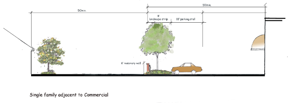
Single family adjacent to Commercial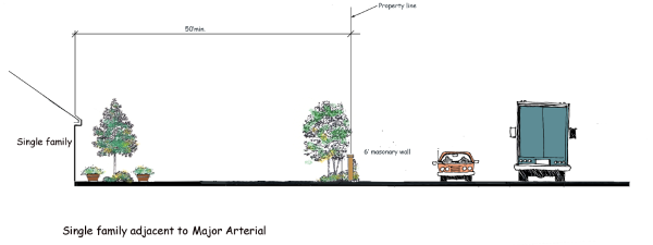
Single family adjacent to Major Arterial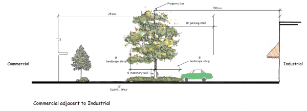
Commercial adjacent to Industrial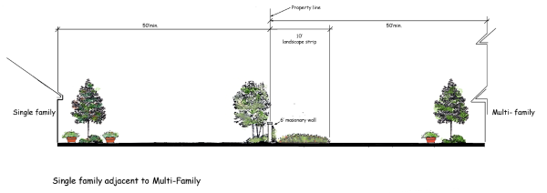
Single family adjacent to Multi-family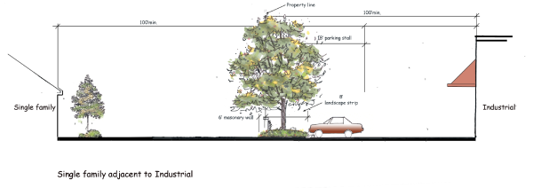
Single family adjacent to Industrial
(Bill No. 2005-F § 2.2, 2005; Bill No. 2006-G, 2006; Bill No. 2007-I, 2007; Bill No. 2010-G, 2010; Bill No. 2012-F, 2012; Bill No. 2015-D, 2015; Bill No. 2018-E, 2019. Bill No. 2019-A, 2019)
16.16.020.4 Landscape Requirements
- Purpose. The purpose of this section is to establish standards for the placement, amount and type of landscape materials and other buffers installed in order to:
- Enhance the aesthetics of the community;
- Encourage the use of xeriscape and hardscape, where appropriate, in order to conserve water resources;
- Provide environmental enhancements such as, but not limited to, the reduction of noise, dust and erosion;
- Reduce visual pollution which might otherwise occur within an urbanized area; and
- Establish a greater sense of privacy from visual and physical intrusion.
- Requirements.
- Determination of permit issuance. No building permit shall be issued to erect, construct, or expand any commercial, industrial or multi-family structure, as well as manufactured/mobile home parks and recreational vehicle parks, unless the planning department first determines that landscaping, as required by this section, should be installed. Landscape plans shall be incorporated into the building permit process and fee schedule. Landscaping plans for common areas and entrances to subdivisions and planned unit developments may be incorporated into the tentative and final plans and will be reviewed as part of the complete package. Single family dwellings are exempt.
- Preliminary plan. A preliminary landscape plan shall be filed with the planning department for the following:
- Any new commercial, industrial or multi-family structure, as well as manufactured/mobile home parks and recreational vehicle parks;
- Any expansion of an existing commercial, industrial or multi-family structure, as well as manufactured/mobile home parks and recreational vehicle parks, unless exempted under subsection B11, "existing buildings", of this section.
- Buffers. Any uses abutting a residentially zoned or used lot shall provide adequate buffering along all common property lines to minimize visual and noise pollution; as an example, buffers may include eight-foot-high sound walls and landscape buffering at the discretion of the planning department.
- Final plan. A final landscape plan shall be approved by the planning department before a building permit is issued. The final landscape plan shall include the following:
- Scale, north arrow, location of adjacent streets, property lines, easements, sidewalks, drives, paved areas, buildings, existing trees (including street trees) and any other natural or manmade site features influencing the use of the site; and
- Low impact development (LID) designs are encouraged to minimize nonpoint source pollution to reduce runoff.
- Minimum coverage. The minimum portion of a site to be permanently landscaped, including required trees in subsection B6, "tree requirements", of this section, shall be approved by the planning director. These should include low impact development (LID) designs to minimize nonpoint source pollution to reduce runoff, and should include:
- Landscape buffers which are a minimum of ten feet in width shall be provided adjacent to the public right-of-way on all state and county-maintained roads. In all other cases, a minimum of five feet of landscaping shall be provided adjacent to other roads.
- All trees located within parking areas shall be located in planting areas protected by concrete curbs.
- Landscape buffers adjacent to residentially zoned or used properties shall be a minimum of five feet in width along common lot lines.
- Tree requirements. Requirements for trees shall be as follows:
- Within the parking area, one tree must be planted for every 15 parking spaces or fraction thereof as determined by section 16.16.020.5 of this section 16.16.020. These trees must be distributed throughout the parking area surface to provide shading within the parking lot.
- Existing mature, healthy trees, as determined by the planning department, may count toward the total number of trees required above.
- Parking lots. Stormwater from parking lots must be kept on-site, and low impact development (LID) designs are encouraged to minimize nonpoint source pollution to reduce runoff.
- Ground cover. Ground covering over the landscaped or otherwise approved area may include:
- Decorative rock or other inert materials.
- Lawn or turf, subject to the limitations in subsection B9, "water usage", of this section.
- Living ground covers other than lawn or turf must be planted in a manner such that the area designed for the ground cover is fully covered within three years.
- Water usage. In order to reduce water consumption, low impact development (LID) designs are encouraged to minimize nonpoint source pollution to reduce runoff, and all nonturf areas shall emphasize low water consumptive plants.
- Certificate of occupancy. The landscape plan must be implemented before the certificate of occupancy is issued, except in the event of a declared drought or during the winter season, in which case the landscaping may be delayed with a letter written to the planning department or building department indicating the reason for the delay and the expected date of installation of the landscaping.
- Existing buildings. When an existing building not in conformance with this section is expanded or the type of use changes, landscaping shall be provided in accordance with subsection B5, "minimum coverage", of this section as approved by the planning department.
- Change in use of an existing building may require a review by the planning director to determine if additional buffer requirements are needed to mitigate impacts.
- The following are exempted from compliance with this section:
- Building permits for interior remodel except in change of use from residential to nonresidential or single-family to multi-family;
- Permits, such as, but not limited to, reroofing, siding, temporary power, change of electrical service, change of furnace, mobile home setup, addition of interior electrical, fencing, on and off premises signs and encroachments;
- Development projects where the existing vegetation to be retained meets or exceeds the requirements of this section.
- Maintenance.
- All landscaped areas must be maintained, including using acceptable pruning standards. A signed copy of a maintenance agreement must be submitted to the planning department with the final landscape plan. Any damaged or dead plant must be replaced or repaired within six months following notification by the building inspector. If the season of the year makes this repair or replacement impractical, the person responsible for landscaping shall schedule an appropriate time with the building inspector for the accomplishment of this work.
- If the repair or replacement is not accomplished in a timely fashion as described above, the director of planning or his designee may initiate proceedings to revoke the business license or special use permit for the subject property.
- Maintenance must include the checking of the sprinkler pattern and drip systems; weeding; fertilization; pest control; replacement of mulches, weed barrier and dead material; proper pruning; and use of proper mowing heights.
- Inspection. Upon installation of landscaping and irrigation systems, the installer must contact the building inspector and request an inspection. The building inspector will inspect the installation and verify compliance with the approved plans before a certificate of occupancy will be issued.
(Bill No. 2018-E, 2019)
16.16.020.5 Parking
- Purpose. The purpose of this section is to establish standards for the placement, amount and type of parking.
- Number of spaces required. The minimum number of off-street parking spaces for each use is set forth in the following subsections. If there are a number of uses on a single parcel, the parking for each individual use is calculated and the total required is the sum of the separate individual requirements, except as provided in section 16.16.020.8 of this chapter. If a garage is counted as required parking, the driveway access to the garage shall not then be counted as required parking. If an accredited source [e.g., Institute of Transportation Engineers (ITE)] provides an acceptable alternative to a parking standard in this section, the director may consider an alternative.
- Off street parking requirements. The following standards are applicable to off street parking for the following land uses:Demands and requirements not clearly indicated herein shall be determined by the planning director based on the particular use and its particular off-street parking demands.
Type Of Use
Parking Requirements
Commercial uses:
Bowling alleys
4 per lane
Casino
1 per 500 square feet of gaming and commercial area
Childcare facility
1 per employee plus 1 space of drop off area per 10 children
Churches
1 per each 5 seats
Drive-through facilities
40 linear feet of stacking area in front of each window or bay plus 1 off street stacking area of 140 linear feet in length (measured from the window)
Financial institutions
1 per 250 square feet gross floor area
Food and beverage service:
High volume restaurant (customer turnover typically less than hourly)
13 per 1,000 square feet plus 1 per employee on largest shift
Lounge area
1 per each 100 square feet
Low volume sit down restaurant (customer turnover typically hourly or longer)
1 per each 3 seats plus 1 per employee on largest shift
General retail, wholesale and services
1 per 300 square feet of retail gross floor area
Hospitals
1.25 per each bed
Hotels
0.8 per room plus parking as required for other uses in the hotel
Manufacturing
1 space per employee for the largest shift and 5 for visitor parking
Motels
1 per room
Offices:
Medical professional
1 per employee and 6 per physician in attendance during operating hours
Professional
1 per 275 square feet of gross floor area
Theaters
1 per each 3 seats
Warehouse
1 per employee
Residential uses:
Boarding house; sorority, fraternity, etc.
1 per each 2 beds
Common kitchen development
1.25 parking spaces per bedroom plus 1 per guest
Congregate care or senior citizen housing (publicly owned or subsidized or privately owned and deed restricted to limit the use to senior or congregate housing)
2 per bedroom and 1 per employee per largest shift plus 1 per 5 dwelling units for guest parking
Multi-family residences
1 1/2 spaces per unit
Rest homes; skilled nursing facility
1 per each 4 beds plus 1 per employee on largest shift
Single-family residence
2 spaces per dwelling unit including mobile home
Upon submittal of accredited documentation (e.g., latest version of ITE parking manual); the director may modify the parking requirements specified herein up to ten percent, or may request planning commission approval of such a modification. - Handicapped parking.
- All parking areas shall have a minimum of one handicapped parking space. This space shall be 13 feet wide for cars and 16 feet wide for vans, clearly identified with signs and painted loading lane, as described in the handicapped parking sections of the Americans with Disabilities Act, with a painted symbol and located within 100 feet of the building entrance. Such spaces shall conform with the requirements of NRS § 484B.467.
- The number of handicapped spaces shall be provided in accordance with the following table:
Total Parking Required
Minimum Number Of Accessible Spaces
1 to 25
1
26 to 50
2
51 to 75
3
76 to 100
4
101 to 150
5
151 to 200
6
201 to 300
7
301 to 400
8
401 to 500
9
501 to 1,000
2 percent of total
1,001 and over
20 plus 1 for each 100 over
- General parking requirements.
- Any off-street parking area proposed for a newly constructed or expanding commercial or industrial use which abuts or faces a single-family, two-family, or multi-family residential district or residential use shall provide screening meeting the director's approval along the side abutting or fronting on such residential district or use.
- Areas adjacent to gas pumps shall not be considered as required parking.
- Newly constructed or expanding commercial uses with parking lots are required to provide a lot with a hard surface such as asphalt, concrete, turf stone type pavers, gravel, or other materials approved by the director. Gravel and other similar materials are permitted for storage and display areas.
- If there is no parking area available on the building site, off street parking as required by this section may be provided on a parcel within 300 feet of the building site upon first securing a special use permit in each case.
- Parking areas shall be used for automobile parking with no permanent sales, storage of equipment or goods or inoperable, unlicensed vehicles or equipment and may not be used for repair work, dismantling or servicing of any kind. Parking areas shall not be used for overnight sleeping or camping.
- Appropriately surfaced parking facilities shall be subject to review as part of a special use permit and shall include consideration of the following:
- Number of employees at major shift;
- Customer requirements;
- Special equipment and vehicle requirements;
- Reserve for planned or possible expansion;
- Access and maneuvering space.
- Driveways or other areas required to move cars in or out of parking spaces shall not be considered in meeting off street parking requirements. Tandem spaces shall only be authorized for individual mobile home units within mobile home parks, RV parks and planned unit developments.
- In calculations, one-half or greater shall constitute one whole parking space.
- Open parking of vehicles accessory to a residential use shall be limited to those actually used by the residents or for temporary parking of guests.
- Owners of public and private parking lots shall not allow recreational vehicles to park and to be occupied for living and/or sleeping purposes.
- Recreational vehicles shall not be parked for living purposes except in approved recreational vehicle parks or where authorized in accordance with this title.
- Off street parking and loading requirements.
- Generally. Permanently maintained off street parking facilities shall be provided in accordance with the provisions of this subsection. When existing buildings are enlarged, off street parking and loading facilities shall be provided in accordance with the provisions of this subsection for the enlargement. When existing residential structures are converted to office or commercial use or from single-family use to multi-family residential use, off street parking shall be provided in accordance with the provisions of this subsection. When approving a business license from one permitted use within a zoning district to another permitted use, or when there is a change of land use or occupancy, additional parking in accordance with this subsection may be required when the planning department determines that the new use would result in a substantial increase in parking demand.
- Location. Unless otherwise specified, all required off street parking shall be located on the premises.
- Use. Parking areas shall be used for automobile parking. Outdoor sales within parking areas shall be short-term and limited and shall not overburden the parking needs of the business associated with the parking area. Storage, repair work, dismantling or servicing of any kind shall not be permitted in parking areas.
- Access. Unobstructed access to a public right-of-way shall be provided, intersecting the right-of-way at an angle of approximately 90 degrees. The Nevada Department of Transportation or the Churchill County road department shall approve all points of access to newly constructed commercial or industrial properties and an encroachment permit shall be acquired.
Driveway approaches shall comply with applicable NDOT or county standards. - Dimensions. Automobile off street parking spaces shall be a minimum of eight and one-half feet wide by 20 feet long, or nine feet wide by 19 feet long. Thirty five percent of the required spaces may be designed for compact vehicles eight feet wide and 15 feet long. Adequate ingress, egress, on premises circulation and maneuvering areas shall be provided. A two-foot vehicle overhang may be permitted where parking abuts a sidewalk with a minimum width of six feet.
- Compact vehicles. Each off-street parking space designed for the exclusive use of compact vehicles shall be signed or marked "compact car".
- Parking for commercial and industrial uses. Off street parking areas for newly constructed commercial and industrial uses shall meet orange book and road department standards and requirements.
- Markings. Off street parking areas shall be striped or otherwise marked so that individual spaces and driving lanes are clearly indicated. Directional markers shall be painted on the driveway surface or placed on standards as required by the planning department.
- Lighting. If lighting is required, it shall be so arranged to reflect away from residential areas and any public street or right-of-way.
- Off street loading. All premises devoted to retail trade, wholesale activities, warehousing, supply houses, hotels, hospitals, laundry and cleaning establishments and other uses where large amounts of goods are received and shipped shall provide off street loading areas as follows:
- One off street loading space for the first 10,000 square feet of floor area plus one additional space for each additional 40,000 square feet of floor area.
- Loading space, exclusive of driveways and/or corridors, shall not be considered as off-street parking space; however, for a building containing less than 3,000 square feet of gross floor area, a combined parking and loading area will be acceptable.
- Off street parking; reductions permitted. The planning commission may permit fewer off-street parking spaces than is otherwise required under the provisions of this section provided as follows:
- A variance is granted by the planning commission.
- With the exception of commercial parking lots in any commercial or industrial zone, all private off street parking areas shall be located on the same property as the use intended to be served.
- Existing off street parking facilities shall comply with recognized and approved standards and dimensions of layout commensurate with individual design limitations.
(Bill No. 2012-F, 2012; Bill No. 2018-E, 2019)
16.16.020.6 Advertising Signs
- Advertising billboards, off premises signs, on premises freestanding signs, and any sign or advertising device, except as provided in subsection B2e of this section, shall be subject to the issuance of a building permit unless otherwise expressly permitted. Signs shall comply with provisions of all applicable state regulations.
- Signs as defined in subsection A of this section shall comply with the following requirements:
- Purpose. The purpose of these sign regulations is to encourage the effective use of signs as a means of communication in the county; to enhance the aesthetic environment to attract sources of economic development and growth; to minimize the possible adverse effects of signs on nearby public and private property; to improve traffic safety.
- Computations. The following principles shall control the computation of sign area:
- Computation of area.
- Signs with one face. The area of a sign face (which is also the sign area of a wall sign or other sign with only one face) shall be computed by means of the smallest square, circle, rectangle, triangle or combination thereof that will encompass the extreme limits of the writing, representation, emblem or other display, together with any material or color forming an integral part of the background of the display or used to differentiate the sign from the backdrop or structure against which it is placed, but not including any framework, bracing or decorative fence or wall when such fence or wall otherwise meets zoning ordinance regulations and is clearly incidental to the display itself.
- Multifaced signs. The sign area for a sign with more than one face shall be computed by adding together the area of all sign faces visible from one point. When two identical faces are placed back-to-back, so that both faces cannot be viewed from any one point at the same time, and when such faces are part of the same sign structure and are not more than 42 inches apart, the sign area shall be computed by the measurement of one of the faces.
- Computation of height. The height of a sign shall be computed as the distance from the base of the sign at normal grade to the top of the highest attached component of the sign. Normal grade shall be construed to be the lower of: 1) existing grade prior to construction, or 2) the newly established grade after construction.
- General standards.
- Building permit required. A building permit shall be required for any sign unless expressly exempted.
- Compliance with codes. All signs shall comply with applicable provisions of the latest adopted edition of the uniform building code, the National Electrical Code and the uniform sign code.
- Maintenance, repair and appearance. All signs shall be maintained in good repair and shall be neat in appearance. Any sign which is determined by the building inspector to be unsafe or unsightly because of bent, broken or missing parts or poor maintenance generally, may be declared a public nuisance.
- Definitions.
Freestanding signs. Any sign, whether on or off premises, supported by structures or supports that are placed on, or anchored in, the ground and that are independent from any building or other structure.
Monument/ground sign. The entire bottom of a ground sign is generally in contact with, or in close proximity to, the ground.
Pole sign. Signs that are supported by a pole(s) and otherwise separated from the ground by air. - Wall signs. Wall signs may not extend above or beyond the wall or surface to which they are attached and may not project more than one foot from the wall.
- Roof signs. Roof signs may not exceed four feet in vertical dimension, may not extend above the upper edge of the roof, below the lower edge of the roof, or beyond the terminating edge of the roof. Roof signs must be constructed separately from the roof surface, must be mounted perpendicular to level grade and parallel to the nearest horizontal roofline, and must have all supports enclosed or otherwise made not visible from the public street or other public area.
- Location of signs.
- Signs located on private property shall not extend across property lines into adjacent property or public rights of way.
- No sign shall be constructed or maintained which has less horizontal or vertical clearance from communication or energized electrical power lines than that prescribed by the laws of the state or rules or regulations of the appropriate agencies.
- All freestanding signs must be located sufficiently back from any right of way to provide adequate sight distance for ingress and egress of vehicular traffic.
- Permits and enforcement.
- Permit required. Except as otherwise provided in this section, it is unlawful for any person to erect, construct, enlarge, alter or relocate within Churchill County any sign or other advertising structure or install or alter any electrical wiring or fixture therein without first having obtained a building permit from the building department and paying the permit fees. Any freestanding sign located on property abutting a state-maintained road must acquire all necessary permits and approvals from the department of transportation prior to application for a Churchill County building permit.
- Application. Application for a building permit to construct/relocate/erect a sign shall be made on forms provided by the county and shall include, or be accompanied by, the following:
- Name, address, telephone number and signature of the property owner;
- Name, address and telephone number of the applicant (owner of the sign);
- Name, address and telephone number of the contractor;
- A plot plan showing the boundaries of the parcel on which the sign(s) is to be located, setbacks from any rights of way, as well as the location of the sign(s) and all structures on the site. Parking and landscaping and other features shall also be indicated;
- Drawings of the proposed sign(s) showing the design, dimensions, mounting, height, materials of construction and structural details;
- Drawings of all existing signs on the site showing their sizes and locations and the total area of all existing signs;
- The location of all freestanding signs within 500 feet of the proposed sign;
- Any other information deemed necessary by the building official or his designee.
- Issuance of permits. Application for a building permit for a sign may be issued when all requirements of this section and this Code have been satisfied and all fees paid.
- Fees. At the time of application applicable building permit fees shall apply.
- Inspection. Any sign which is subject to this section shall be inspected by the building official to ensure compliance with this section and the building code.
- Suspension and revocation. Any permit issued in error, or in reliance on a falsified application, may be revoked by the building department. Any sign erected or partially erected under a permit issued pursuant to a falsified application may be ordered removed at the owner's expense.
- Variance of area. Where practical difficulties or extenuating circumstances exist such that the applicant cannot meet the requirements of this title, a variance may be applied for.
- Signs exempt from permit. No permit shall be required for any of the following signs, but such signs shall be erected and maintained in accordance with the provisions of this section:
- Official traffic control or regulatory signs, signals or devices, handicapped signs, street name signs or other signs required by law.
- Professional occupation signs denoting only the name or firm name and profession of an occupant in a commercial building, public institutional building or dwelling house when the area of such sign does not exceed two square feet for each professional occupant therein and placed on or against a building.
- Memorial tablets, plaques or markers of bronze, stone or concrete.
- Address numbers or plates and residential nameplates.
- Bulletin boards not over 15 square feet in area, for public charitable and religious institutions when such bulletin boards are located on the premises of said institutions.
- Off premises directional signs advertising places of public worship and assembly, hospitals, schools and institutions supported by charitable organizations subject to the following conditions:
- There shall be not more than two such signs on one parcel advertising any one use unless authorized by the planning commission.
- Each such sign shall not exceed three square feet in area.
- Temporary signs and banners of a civic, charitable, educational, municipal or religious nature not to exceed a period of 90 calendar days.
- Pennants, banners, balloons, and similar advertising devices located on private property advertising a special event or sale. Such devices must be removed within seven days of the event.
- Temporary signs on the interior of windows of commercial buildings.
- The changing of advertising copy or message on a painted or printed sign specifically designed for the use of replaceable copy.
- Real estate signs advertising the sale or lease of a property or open house provided no such sign exceeds four square feet in area and three feet in height, in all agricultural and residential zones, or 32 square feet in area and five feet in height in commercial and industrial zones, and is placed on premises.
- Temporary construction signs advertising the name of the contractor, lender or other professional, provided no such sign exceeds 32 square feet in area and six feet in height and is placed on the premises where the structure is being constructed. Temporary signs shall be removed within 30 days after the certificate of occupancy is issued.
- Political signs, signs designed for the purpose of advertising support of or opposition to a candidate or proposition at public election. Political signs shall be removed within 30 days after the election.
- Temporary on and off premises signs with messages such as, but not limited to, "for rent", "for sale", "garage sale", "open" or "closed"; provided, that no such sign shall exceed three square feet in size and must not be affixed to trees or shrubs. Temporary signs shall be removed within seven days after the event.
- On premises directional signs that enhance the flow of traffic and are less than nine square feet in sign area.
- Prohibited signs. The following types of signs and displays are prohibited:
- Signs which constitute a hazard to traffic or pedestrians;
- Signs located within any stream or drainage channel;
- Mobile signs or portable signs unless in conjunction with an approved special event. Said signs must be removed within seven days of the event;
- Signs which produce odor, sound, smoke, flame or other emissions;
- Signs which imitate or simulate official signs, or which use yellow or red blinking or intermittent lights resembling danger or warning signals;
- Signs on public property or rights of way; signs attached to utility poles, streetlight standards, trees or fences;
- Off premises signs in the RR-20, A-10, A-5, E-1, R-1, R-2 zoning districts, unless one of the following criteria apply:
- It is in conjunction with a bona fide farming operation.
- It is in conjunction with a land use where a special use permit has been issued by the planning commission. The height and sign area of the sign must not exceed the requirements for signs in the C-2 zoning district as outlined in subsection B2g(4) of this section.
- Size requirements per zoning district.
- Agricultural and residential zoning districts (excluding R-2):
- On premises signs: Only in conjunction with special uses approved by the Churchill County planning commission. The proposed sign design standards must be approved as part of the special use permit application.
- The maximum height of the sign must not exceed 25 feet.
- Maximum allowable sign area: 160 square feet.
- Illumination: Indirect only.
- R-2 zoning district:
- Maximum height of freestanding signs: 12 feet.
- Maximum allowable sign area: 12 square feet.
- Illumination: Indirect only.
- Where a special use permit has been issued for a land use the proposed sign design standards must be approved as part of the special use permit and must not exceed the following:
- Maximum height: 25 feet;
- Maximum sign area: 160 square feet.
- C-1, C-2, west of Sheckler cutoff and Roberson to Lyon County, and I zoning districts:
- Dimensions.
- Pole signs: Maximum height, 25 feet; maximum sign area, 160 square feet; minimum 100 feet between any pole signs and 50 feet between any pole sign and ground sign.
- Ground signs: Maximum height, four feet; maximum sign area, 80 square feet; minimum 50 feet between any two ground signs or a ground sign and a pole sign.
- Maximum total sign area for all freestanding signs on one parcel of land, except exempted directional signs: 160 square feet.
- Projecting signs: Maximum sign area, eight square feet.
- Wall signs: Maximum sign area, ten percent of total wall area on which it is to be placed.
- Prohibited location. No freestanding sign may be located in a position where it intentionally obstructs the view of any other freestanding sign.
- Master signage plan. A master signage plan may be required when there is more than one business located on one parcel.
- Special use permit. The planning commission may issue a special use permit for any freestanding sign advertising four or more businesses located on one parcel if there are no other freestanding signs within 100 feet of said sign and if the applicant provides sufficient evidence to show that the proposed sign would be more beneficial to the community than several freestanding signs on the same property. The sign area may not exceed 200 square feet.
- Dimensions.
- C-1, C-2, east of Sheckler cutoff and Roberson to Carson River Bridge and all other C-2 not specified:
- Dimensions.
- Pole signs: Maximum height, 20 feet; maximum sign area, 140 square feet; minimum distance between any pole sign 100 feet; minimum distance between any two ground signs or a ground sign and pole sign, 50 feet.
- Ground signs: Maximum height, four feet; maximum sign area, 70 square feet; minimum 50 feet between any two ground signs or a pole sign and a ground sign.
- Maximum total sign area for all freestanding signs on one parcel of land: 140 square feet.
- Projecting signs: Maximum sign area, eight square feet.
- Wall signs: Maximum sign area, ten percent of total wall area on which it is to be placed.
- Prohibited location. No freestanding sign may be located in a position where it intentionally obstructs the view of any other freestanding sign.
- Master signage plan. A master signage plan may be required when there is more than one business located on one parcel.
- Special use permit. The planning commission may issue a special use permit for any freestanding sign advertising four or more businesses located on one parcel if there are no other freestanding signs within 100 feet of said sign and if the applicant provides sufficient evidence to show that the proposed sign would be more beneficial to the community than several freestanding signs on the same property. The sign area may not exceed 175 square feet.
- Dimensions.
- C-1, C-2, east of the Carson River to city limits and any C-1 zoning area not listed above:
- Dimensions.
- Pole signs: Maximum height, 20 feet; maximum sign area, 120 square feet; minimum distance between any pole sign, 75 feet; minimum distance between any two ground signs or a pole sign and ground sign, 50 feet.
- Ground signs: Maximum height, four feet; maximum sign area, 60 square feet; minimum 50 feet between any two ground signs or a ground sign and a pole sign.
- Maximum total sign area for all freestanding signs on one parcel of land: 120 square feet.
- Projecting signs: Maximum sign area, eight square feet.
- Wall signs: Maximum sign area, ten percent of total wall area on which it is to be placed.
- Prohibited location. No freestanding sign may be located in a position where it intentionally obstructs the view of any other freestanding sign.
- Master signage plan. A master signage plan may be required when there is more than one business located on one parcel.
- Special use permit. The planning commission may issue a special use permit for any freestanding sign advertising four or more businesses located on one parcel if there are no other freestanding signs within 100 feet of said sign and if the applicant provides sufficient evidence to show that the proposed sign would be more beneficial to the community than several freestanding signs on the same property. The sign area may not exceed 100 square feet.
- Dimensions.
- Subdivision and residential development sales signs:
- On premises sales signs. Notwithstanding any other provisions of this section, a total of 40 square feet of sign area used in one or two nonilluminated signs may be affixed to each subdivision of land to identify the name of the development, as well as the name, address and telephone number of the seller or his/her agent, provided that:
- A building permit is acquired.
- The signs must be at least 200 feet apart.
- The signs are located on or within the development.
- The signs must be maintained in good repair.
- The signs must be removed upon close of escrow of the last residence constructed by the developer or the close of the sales office, whichever occurs first.
- Identification/entrance signs. Permanent identification signs may be placed at the entrance to an approved subdivision or residential development provided that:
- The size and location of the signs are provided and approved as part of a tentative map or final map submittal or a special use permit is approved by the planning commission for each proposed sign.
- The signs are located on or within the development at the primary entrance(s).
- The sign area shall not exceed 40 square feet.
- The sign must be maintained and in good repair.
- The signs are nonilluminated.
- On premises sales signs. Notwithstanding any other provisions of this section, a total of 40 square feet of sign area used in one or two nonilluminated signs may be affixed to each subdivision of land to identify the name of the development, as well as the name, address and telephone number of the seller or his/her agent, provided that:
- Agricultural and residential zoning districts (excluding R-2):
- Nonconforming signs.
- Right to maintain and continue the use of a nonconforming sign. A nonconforming sign may be maintained and continued in use; provided, that:
- It is not altered, enlarged or relocated without a sign permit;
- It is maintained in good repair and does not become unsightly or hazardous.
- Termination of right to nonconforming sign.
- Any nonconforming sign which is declared a hazard by the building official shall be removed or repaired within ten days of notice to the owner of the sign.
- Any nonconforming sign which requires repairs costing in excess of 50 percent of its replacement value shall be removed or made to comply with the provisions of this section.
- Right to maintain and continue the use of a nonconforming sign. A nonconforming sign may be maintained and continued in use; provided, that:
- Computation of area.
(Bill No. 2005-F § 2.2, 2005; Bill No. 2006-G, 2006; Bill No. 2007-I, 2007; Bill No. 2015-D, 2015)
16.16.020.7 Lighting (Dark Skies)
Lighting shall be limited to illuminating the site and will be designed to utilize downward facing lighting and lighting that is shielded to minimize off site light and glare.
(Bill No. 2015-D, 2015)
16.16.020.8 Other Development Standards For Specific Land Uses
- Accessory dwelling unit. "Accessory dwelling unit" refers to a structure on the same parcel of land as the primary dwelling unit and may be attached or detached from other structures. Typical uses include housing for guests, extended family housing and caretakers' quarters. An accessory dwelling unit is not intended as a second permanent dwelling unit. An accessory dwelling unit shall comply with the following conditions:
- An administrative special use permit approved by the planning director must be acquired.
- An accessory dwelling unit shall not exceed 1,000 square feet in total habitable area.
- Only one accessory dwelling unit is permitted per parcel.
- If manufactured housing or a modular home is being used for the accessory dwelling unit, it must be a new unit that has never been lived in.
- A landowner may live in an accessory dwelling unit while the main residence is being constructed if the building permit has been issued and all applicable fees and dedications have been completed for the main residence; or a landowner may live in an accessory dwelling unit prior to application for the building permit for the main residence if all the fees and dedications are completed at the time the building permit for the accessory dwelling unit is issued. A landowner may change the designation of a single-family residence from primary dwelling to accessory dwelling unit if the building meets the accessory dwelling unit criteria and the landowner subsequently builds another single-family residence as the primary dwelling. Impact fees and dedications are not applicable to the new single-family residence if these were paid for the single-family residence that is being redesignated. The landowner must apply for an administrative special use permit for approval of this redesignation.
- Kitchen facilities may be installed. A minimum of one bathroom per accessory dwelling unit must be installed.
- Permission to rent an accessory dwelling unit requires the unit to meet all listed requirements and the owner of the property must live on the parcel. Parcels with accessory dwelling units in which the property owner does not live on the parcel are prohibited from being rented separately from the main dwelling, and a deed restriction stating the accessory dwelling unit shall not be let, leased or rented separately from the primary dwelling unit will be recorded as part of the approval, except as provided under this section.
- The owner of an accessory dwelling unit is not required to comply with the water right dedication ordinance or pay impact fees. A meter shall be installed on the water well per NRS § 534.180(4).
- The accessory dwelling unit must use the same property address as the primary dwelling unit.
- An accessory dwelling unit may be permitted in any residential land use district or on any parcel where a legal existing permanent dwelling exists. The construction of an accessory dwelling unit must comply with dwelling setbacks, easements, and all other land use regulations for the land use district. Such construction shall also be subject to enforcement of any protective covenants, conditions and restrictions relating to the subject property, by any person having legal standing to do so.
- A site plan shall be submitted with the administrative special use permit application indicating the following:
- Location of primary residential structure with setback distance, distance to accessory dwelling unit and other accessory structures, and easements.
- Location of all public and private utilities and/or well and septic tank/leach field.
- Access to primary residential structure and accessory dwelling unit.
- Zoning, size of lot, assessor's parcel number, north arrow, scale, location of other outbuildings.
- Home based businesses. Home based businesses may be approved through a home business permit or a special use permit, as identified for the site's zoning district in the use table under section 16.08.250 of this title. Home based businesses must meet the conditions listed below for the appropriate review process to be approved. If the conditions for a home business permit cannot be met, the applicant may apply for the special use permit if they meet the broader conditions.
- Conditions pursuant to a home business permit may be approved administratively:
- All owners shall reside in the residence. The only employees allowed to work on-site are family members residing in the residence. No other employees can report to the residence for work. In the case of contract work, they shall report directly to the job site and not the applicant's property.
- The appearance of the structure shall not be altered, no new structures built for the business, nor may business activities be conducted outdoors or in such a manner that would take away from the residential characteristics of the property beyond what is allowed in these conditions, i.e., one cannot have merchandise or services visible from outside the dwelling or generate excessive noise.
- The home-based business may involve the use of one commercial vehicle that is approved by the planning department, i.e., vans and medium sized trucks (only one semi-tractor and trailer for an over the road haul truck driver that may occasionally be at the residence).
- Equipment that causes any type of interference in radios, televisions, or telephones, etc., or causes fluctuations in line voltage outside the dwelling unit is prohibited, i.e., excessive usage of power equipment.
- Outside storage of construction or raw materials is not allowed. One cannot store any toxic or hazardous materials at a quantity that requires a permit from the state of Nevada or any other agency charged with the regulation of hazardous materials. Inventories of drugs, alcohol, fireworks, or explosives (excluding ammunition) are not allowed. Storage of business vehicles must meet the vehicle condition. No outside storage of construction or other similar equipment is allowed with the exception that one piece of equipment (such as a trailer) may be allowed with the approval of the planning department; lawn care and other similar equipment may be allowed with approval of the planning department, but not to exceed a quantity that can be hauled and stored on a single pickup and trailer.
- No signs may be placed on the property to advertise the home-based business. One may advertise one's business through public media, business cards, stationery, etc.
- No customer traffic is permissible. Home deliveries, such as UPS, FedEx, etc., in a quantity/frequency that will not be detrimental to the surrounding neighborhood may be permitted.
- If the applicant is not the property owner, the property owner must authorize the use of the property for the proposed home-based business in writing.
- If any of the conditions for a home business permit cannot be met, the applicant may apply for a special use permit pursuant to section 16.08.080 of this title. The conditions for a home business permit continue to apply and may not be exceeded, except as specifically described in the conditions below.
- A limited number of employees that work at or report to the site may be allowed.
- Exterior alterations or new structures to accommodate the business are allowed through a special use permit. Outdoor business activities, other than those allowed in these conditions, are not allowed, except that equestrian businesses, kennels and landscaping businesses with outdoor activities may be approved through a special use permit. Conducting business in a way that takes away from the residential character is not allowed.
- The number and size of commercial vehicles allowed may be increased through a special use permit (for example, tow trucks, construction equipment, or semi tractors and trailers for a trucking company).
- No additional radio, power, or other interference is allowed.
- No additional storage of toxic or hazardous materials, drugs, alcohol, fireworks, explosives, etc., are allowed. Outside storage of business-related materials and equipment is allowed through a special use permit if it is fully enclosed by screened fencing or buildings and is less than one-fourth acre in area.
- Signage up to ten square feet in area may be allowed through a special use permit.
- Additional customer traffic and deliveries may be allowed through a special use permit.
- No exception to obtaining authorization for the business from the property owner is allowed.
- Conditions pursuant to a home business permit may be approved administratively:
- Dwellings attached to commercial operations.
- Single-family dwelling attached to a ministorage facility, subject to an administrative review and the following conditions:
- The gross square footage of habitable area shall not be greater than 1,200 square feet.
- The habitable area may only be occupied by the owner acting as the manager or caretaker or persons employed by the owner of the property as a manager or caretaker of the storage facility.
- The living area must be attached to the storage facility, preferably on the second floor and be an integral part of the development.
- The office space for the storage facility shall not be a part of the habitable area.
- Single-family dwellings attached to a small commercial operation shall be allowed pursuant to a special use permit only in the C-1 district such as an art studio, and custom and craft work, and subject to the following conditions:
- The gross square footage of habitable area shall not be greater than 1,200 square feet.
- The habitable area may only be occupied by the owner of the commercial operation.
- The living area must be attached to and be an integral part of the structure for the commercial operation.
- Single-family dwellings may also be permitted pursuant to a special use permit in the C-1 or C-2 district where one of the following conditions exists:
- The proposed single-family dwelling is to be located on a bona fide farming or ranching operation for use by the owner or manager of the farming operation.
- A home based business related to an agricultural operation will be conducted from the proposed single-family dwelling.
- The single-family dwelling is recognized as part of the heritage and landscape of Churchill County.
- Single-family dwelling attached to a ministorage facility, subject to an administrative review and the following conditions:
- Recreational vehicle uses and standards.
- A recreational vehicle may be parked on private property where there is a single-family dwelling in any land use district for an unlimited period of time when not being used for temporary shelter or storage.
- A recreational vehicle being used as temporary shelter by persons traveling and visiting friends, family, and relatives may be parked on private property outside the confines of a recreational or mobile home park for a period not to exceed 90 cumulative days.
- A recreational vehicle is prohibited from being used as a permanent residence or shelter unless a temporary use permit has been obtained as outlined in chapter 16.08, "Zoning And Land Use", of this title.
- Criteria for permanent housing for farm labor.
- Demonstration of the need for farm labor.
- The total farm/ranch acreage must be sufficient so that the total number of housing units does not exceed the density of the land use district within which the farm is located (for example, a 500-acre farm in the A-10 land use district may not exceed a total of 50 permanent dwelling units).
- The permanent housing must be placed on the ranch or a parcel contiguous to the farming operation.
- Temporary real estate office for sales in subdivision. A temporary real estate office within an approved subdivision is permitted for the purpose of selling lots in the subdivision and not for the conduct of a general real estate office.
- Nontraditional single family residence construction standards. The purpose of these standards is to limit the use of small-size substandard alternatives in creating a single-family residence.
- Small single-family residences. Small primary single-family residences, whether stick built or manufactured, with a living space area of under 1,200 square feet are prohibited in the E-1, R-1, and R-2 zoning districts.
- Park model trailers and recreational vehicles. Park model trailers and recreational vehicles are not considered single family dwellings, and are prohibited as permanent residences. They are constructed by manufacturers to industry standards that are acceptable for temporary living situations. They may be used in a mobile home/recreational vehicle park, or as approved in a temporary use permit.
- Shipping container dwellings. Shipping containers are prohibited for use in the construction of a permanent or temporary single-family dwelling in the E-1, R-1, and R-2 zoning districts; but may be considered for use in multi-family or manufactured home park development, when such is allowed in the district, and when reviewed through a special use permit. In all allowed cases, shipping containers used in dwellings must meet the International Building Code standards for use as a dwelling, and must meet all other County Code requirements.
- Sheds. Buildings that are customarily used as storage sheds, garden sheds, tack sheds, or similar buildings, including those that are mobile or on wheels, are prohibited for use as a temporary or permanent residential dwelling in all land use districts regardless of their design, size, or construction.
- Second permanent dwelling. There may be one or more permanent single-family dwellings on any lot or parcel; provided there is not less than the required minimum acreage for each dwelling and that such dwellings are not less than 40 feet apart. The applicant shall provide a drawing to scale of the property indicating locations of existing houses, wells, and septic tanks, improvements, setbacks, access, and location of the proposed dwelling with the administrative special use permit application. Adequate information must be provided to indicate how the parcel could be divided in the future. Each additional residence is subject to impact fees as provided in this Code.
- Multi-family development shall meet the standards below:
- Allowed density is based on the acreage of the subject parcel, except that residential densities for a planned unit development shall be determined with its approval. When calculating the density of dwellings in a multi-family development, exclude road right-of-way areas, and exclude the area of commercial and other nonmulti-family-residential uses along with the associated parking and accessory features, as determined appropriate by the Director. The area of residential amenities and business office may be included. The calculation does not preclude placement of residential units in the same building as, or above commercial and other uses.
- All developments shall provide open space in the form of landscaping around the development to a distance at least equal to the required setbacks, excluding private areas assigned to individual units and separated by fencing or other features. The landscaping plan shall use vegetation to the satisfaction of the director, should include areas usable by residents, and shall meet other landscape requirements in this title.
- Developments of five or more dwelling units shall provide common open space to total at least 20 percent of the developed area. Areas qualifying as open space must be improved with outdoor amenities or landscaping (including required buffers that are landscaped), and may include the landscaping required in paragraph 2. The applicant may request that the director authorize special natural resources, such as wetlands or river corridors, to be included as open space without improvements. Open space may not include building areas, parking spaces or driveways, utility service areas, stormwater basins (unless designed as an amenity), or agricultural easements (for canals, ditches and drains).
- Developments of 20 or more dwelling units shall provide one active amenity/50 units, with fractions rounded up. Outdoor amenities may be incorporated into the required landscaping and open space areas.
- All developments shall provide a patio or balcony for each dwelling unit, central or in-unit laundry facilities, and a central trash collection location that is visually screened.
- Required parking for multi-family developments shall be provided off-street. Where all parking spaces are dedicated to individual dwellings, the decision maker may require additional parking spaces for visitor use.
(Bill No. 2005-F § 2.2, 2005; Bill No. 2006-B, 2006; Bill No. 2006-G, 2006; Bill No. 2007-I, 2007; Bill No. 2010-G, 2010; Bill No. 2012-F, 2012; Bill No. 2015-D, 2015; Bill No. 2017-D, 2017; Bill No. 2018-E, 2019; Bill No. 2019-A, 2019; Bill No. 2020-A, 7-2-2020; Bill No. 2022-A, 4-20-2022)
16.16.030.1 Facility Development And Performance Standard
Unless otherwise stated in this section, each restriction and requirement shall apply to all power generation facilities (PGF). It is recognized that the standards herein are neither exclusive, nor exhaustive. In instances where a health, safety, or environmental concern is known to exist with regard to any REF, additional proportional mitigating conditions may be imposed on the facility by Churchill County. The following shall apply as indicated above:
- Building permit. In addition to the requirements set forth by this section, applicants shall be required to obtain a Churchill County building permit prior to construction of any PGF. The use of nonreflective or minimally reflective construction materials, and solar tracking and other technologies for all new energy projects is recommended to reduce the impact on military operations, residential locations, or roadways.
- Communications and electromagnetic interference. All PGFs shall be sited and operated so that they do not interfere with existing military/department of defense (DOD) or emergency (fire, police/sheriff, ambulance) radio two-way communications (base stations, mobile, and handheld radios, including digital) and/or paging, television, telephone (including cellular and digital), microwave, satellite (dish), navigational, internet or radio reception to neighboring areas. The PGF must comply with Federal Communications Commission (FCC) regulations. The applicant and/or operator of the facility shall be responsible for the full cost of any remediation necessary to provide equivalent alternate service or correct any problems; including relocation or removal of the facility caused or exacerbated by the operation of such equipment and any and all related transmission lines, transformers, and other components related thereto. The applicant shall maintain equivalent communications throughout the life of the PGF even as future technologies may change. The applicant must maintain an FCC license to own and operate two-way radio operations. The owner/operator shall fulfill the following requirements when needed throughout the life of the facility:
- Respond within five business days to any request for communications interference investigation by a property owner within the project boundary and a one-mile radius beyond the project boundary; provided, however, that this requirement shall not apply to repetitive requests pertaining to an issue for which an investigation has previously shown that the PGF is not the source of the interference. Testing will commence within ten working days of a substantiated request. The owner/operator is responsible for mitigating within ten working days from the determination of interference known to be caused by the operation of the PGF.
- Respond within one business day to any request for communications interference investigation by any emergency agency (fire, police/sheriff, ambulance). Testing shall commence within two business days of the request. The owner/operator is responsible for mitigating or initiating reasonable efforts to mitigate.
- Public roads and rights-of-way. Prior to construction and use of roads, the applicant of a commercial PGF shall consult with the Churchill County road department (CCRD) and shall be required to enter into an agreement with CCRD regarding public access and proportional maintenance and repair of existing roads, or abandonment of roads.
- Transfer of entitlement. A commercial PGF owner shall notify the planning department of the sale or transfer of property in whole or in part to any person, partnership, joint venture, firm, company, or corporation. The new owner/operator will be provided a copy by the planning department of all notices of decision regarding the facility and shall be required to acknowledge receipt of such notice(s). This provision shall not apply to financing transactions or any transfer to an affiliate of the owner.
- Special use permit maintenance. In the event that the use authorized by the special use permit is abandoned for a period of more than 365 calendar days from the date of last producing operations, the permit shall become null and void and a new special use permit shall be required if operations are subsequently resumed. Notwithstanding anything to the contrary contained in this section, or in subsection 16.08.080H2 of this title, or in similar permit expiration or abandonment provisions of this Code, the term "abandonment", as applied to PGFs, shall not be construed as applying to a facility with regular on-site employees, maintenance, and security, regardless of whether commercial production at the facility has temporarily lapsed. In the event of a force majeure event, such as, but not limited to, a flood, damage, or destruction of the access to the site, earthquake, or other events beyond the control of the County or permit holder, the period of abandonment shall not be deemed to commence until such time as the permit holder may be found to once again have reasonable access to the site. The permit holder shall reasonably attempt to establish access to the site. The special use permit shall remain valid as long as the permit holder, its heirs, assigns, or successors remain in compliance with the terms of this permit and county, state and federal regulations. In the event that the permit lapses or the use is discontinued or abandoned, the permit holder/owner, its heirs, assigns or successors shall remain responsible for environmental compliance until postclosure reclamation requirements are met. If the facility is not being abandoned, but is not in operation for greater than 365 days for a reason such as equipment failure, replacement, or maintenance, the PGF contractor shall notify the planning department in writing indicating an estimated time line for operations to recommence.
- Liability insurance. The PGF owner, as well as its assigns, heirs or successors, shall provide proof of liability insurance to Churchill County and maintain satisfactory insurance covering all aspects of the facility operation in the amount of at least $1,000,000.00 for each PGF prior to initiating operations. Churchill County reserves the right to require additional liability insurance coverage as needed by special circumstances such as REF proximity to population, use of large quantities of hazardous/flammable materials, and/or known impact/influence on aquifer(s) used by the public.
(Bill No. 2017-E, 2017)
Amended by Ord. Bill 2025-A, Ordinance 32 on 9/17/2025
16.16.030.2 Monitoring Requirements
The applicant shall provide a copy of any monitoring plan submitted to state or federal agencies to Churchill County. If no such plan is required by/submitted to state or federal agencies, Churchill County reserves the right to require submission of a proposed monitoring plan or written justification of why none should be required. Churchill County will determine whether a plan is required, in such case, and will reasonably determine the requirements/parameters of such plan in collaboration with the applicant and appropriate consulting agencies and qualified individuals.
(Bill No. 2010-C, 2010)
16.16.020.3.1 Outside Storage
"Outside storage" means the use of a portion of a lot or area for the long-term retention (more than 24 hours) of materials, tools, equipment and machinery, regardless of whether the materials, machinery, or equipment are to be bought, sold, repaired, stored, or discarded. This includes, without limitation, pipes, tools, equipment, etc., used to conduct the business and not for retail sale; it does not include, without limitation, trucks, trailers, and large vehicular equipment used for a business, such as drilling rigs and other heavy construction equipment. This term does not include new or used motor vehicles, trailer and other retail display outside the primary business structure that are accessible by the public. Outside storage areas are generally accessible by employees only.
The provisions of this section shall apply to new construction for commercial uses and a change in use of an existing commercial structure, unless otherwise specified herein.
- In the C-1, C-2, and I districts, outside storage areas, excluding storage sheds or shipping containers, shall be enclosed by a sight obscuring fence or wall, permanently installed and maintained at a minimum height of six feet; no materials shall be stored therein to a height exceeding that of the wall or fence.
- Storage areas shall not be located within any required yard setback or parking areas nor shall they be located in any way which interferes with normal traffic flow onto, within or from the lot, or which impedes sight distance at intersections, or which otherwise impedes driver visibility.
- Shipping containers or other similar enclosures used for storage are allowed in all land use districts unless prohibited by legal restriction. There may be only one shipping container per acre on a parcel, and not more than two containers per parcel in the E-1, R-1, R-2, A-5, A-10 and RR-20 districts; bona fide commercial farming or ranching operations are excluded from this limitation. Shipping containers may not be stacked and must be maintained in good condition.
(Bill No. 2018-E, 2019)
16.16.020.3.2 Outside Display Of Goods And Merchandise
"Outside display of goods and merchandise" means the setting up and display of household goods and merchandise outside of a primary structure for the purposes of selling the goods. This includes, but is not limited to, yard/garage sales from homes or ministorage facilities storing personal household goods; temporary outdoor sales and activities (as defined) or promotional events outside the primary structure of a commercial operation such as clearance sales, street vendors, sale of pumpkins and Christmas trees, pet adoptions, etc.; permanent display of merchandise associated with businesses such as nurseries and landscaping, automobile rental and sales, and equipment rental and sales.
- Purpose. The purpose of this section is to maintain the noncommercial character of residential neighborhoods and to promote orderly development in commercial and industrial zoning districts to attract new business development and enhance our quality of life.
- Application. The provisions of this section are applicable to existing and new uses in all land use districts with the following limitations:
- Outside display at residential locations and ministorage facilities:
- Limited to the sale of personal household belongings.
- Limited to four per year (e.g., three consecutive days is calculated as one sale, two weekends in one month is considered two sales).
- Outside display at commercial locations:
- Any outside display, whether permanent or temporary, shall not be located in easements or street rights-of-way, on sidewalks, in setbacks, in parking areas, nor shall it be located in any way which interferes with normal traffic flow onto, within or from the lot, nor which impedes sight distance at intersections, or which otherwise impedes driver visibility.
- Street vendors must provide for parking out of road easements and rights-of-way, allow for regular traffic flow and prevent congestion in the area. Traffic control signs must be placed to identify parking spaces and traffic flow. Where there are no legally marked parking spaces, the vendor must provide an area for parking that is out of easements and rights-of-way or backs of the curb/sidewalk in the interest of public safety.
- Display of household merchandise and goods, such as clothing, appliances, furniture, books, electronic equipment, toys, and the like, but does not include automobiles, trailers, equipment, and other items normally used or stored outside, is limited to the hours of operation and cannot be left outside overnight.
- Outside display at residential locations and ministorage facilities:
(Bill No. 2012-F, 2012; Bill No. 2018-E, 2019)
16.16.030.3.1 General Provisions
- Purpose. The purpose of this section is to require supplemental provisions to those required for all power generation facilities in order to manage the exploration, development and use of geothermal resources.
- Applicability. The provisions of this section 16.16.030.3 shall apply to all geothermal projects and related power generation facilities. This includes the use of fluid or steam for energy production from any geothermal well(s) within the unincorporated areas of the county. All geothermal development for commercial and industrial uses shall require a special use permit, unless otherwise specified in the provisions of this section 16.16.030.3. A geothermal development project consists of all wells, access roads, surface equipment, facilities, pipelines and electric transmission lines.
- Required permits. All geothermal development shall be required to obtain all necessary permits from the regulatory agencies with authority over such development, including the Nevada Division of Minerals, the Nevada Division of Environmental Protection (NDEP), the Nevada Division of Water Resources, the Nevada Division of Public and Behavioral Health, the U.S. Bureau of Land Management (BLM) and U.S. Bureau of Reclamation (BOR) prior to the issuance of any building permits for the project. Each entity above may have separate departments that may have separate requirements, i.e., NDEP requires air pollution permit, water pollution permit, and chemical accident protection program permit, etc.
- Geothermal exploratory project. A geothermal exploratory project is for the purpose of evaluating the presence and characteristics of geothermal resources prior to starting a geothermal field development project.
- Prior to commencing a geothermal exploratory project the developer shall provide written notice to the Churchill County planning director that includes the following:
- A description of the project including a map of appropriate scale showing the location of proposed wells and effluent disposal.
- A description of the potential impacts to the local community or natural environment.
- A statement that the applicant agrees to provide to the county access to the data used to develop the conceptual aquifer model. The county shall not take possession of this information, rather the applicant shall make the information available for inspection by county officials, or designated agent(s), provided that the county officials or designated agent(s) who inspect the information sign an agreement that the information will not be disclosed or made available for public dissemination.
- Prior to commencing a geothermal exploratory project the developer shall provide written notice to the Churchill County planning director that includes the following:
(Bill No. 2017-E, 2017)
Amended by Ord. Bill 2025-A, Ordinance 32 on 9/17/2025
16.16.030.3.2 Geothermal Well Field Gathering Systems And Power Generation Facilities
- Required Submissions. The provisions of this section shall apply to geothermal well field gathering systems. All geothermal well field gathering systems and power generating facilities require a special use permit pursuant to section 16.08.080 of this title. Concurrent with submittal of the special use permit application, and specifically subject to, and limited by, the confidentiality requirements of section 16.16.030.3.1 of this chapter the applicant shall provide to the county a conceptual aquifer model and plans for monitoring. In addition, copies of all monitoring and reclamation plans, and any aquifer models, required by federal and state agencies shall be provided as soon as possible, preferably with the application, which may be after issuance of any applicable zoning permit. If there is a regulatory gap and no such plans and/or models are required by other agencies, Churchill County reserves the right to require submission of the following:
- Monitoring Plan. The applicant shall prepare a monitoring plan, which must be approved by Churchill County, unless Churchill County grants a waiver based upon its review of the conceptual aquifer model. The monitoring plan shall comply with Nevada Administrative Code (NAC) 445A.810 through 445A.925, Underground Injection Control, and all pertinent laws and regulations established by any other state, federal or local jurisdiction. Prior to commencement of any operations of the geothermal well field and power generating facility, baseline data representation and collection shall be established to the satisfaction of the county. Projection of geothermal fluids use and injection will be presented to the county as well as a conceptual model. The monitoring plan must be approved by Churchill County, or authorized representative, prior to any operation of the facility.
- Numerical aquifer model. The applicant may be required to prepare a numerical aquifer model based on collection of three years of data following commencement of operations. The model shall be designed to show hydrogeological and thermal data to enable modeling of impacts of pumping and injection and potential mitigation actions. The model shall include data on the following:
- Thermal properties of the aquifer which will include local and large-scale impact to local geothermal uses.
- Potential subsidence impact based upon an analysis of existing and predicted conditions based on pumping and injecting volume of the proposed project.
- Changes in radioactive characteristics from pumping, if any.
- Groundwater aquifer: physical and chemical change before and after project completion. This includes pressure, temperature trends, volumes and water chemistry.
- Siting of geothermal well field gathering systems and power generation facilities. Geothermal well field gathering systems and related power generation facilities shall be sited in zoning districts as listed in the Use Table If necessary, a zone change application must be requested and obtained prior to any permits for the geothermal well field gathering system being issued.
- Proximity to water wells. Geothermal temperature gradient and exploration/development test wells shall be situated with a minimum separation of 3,000 feet from any adjacent private domestic well(s) unless a lease exists between the domestic well owner and the geothermal developer, or one-half mile from state permitted municipal and industrial or quasi-municipal and industrial purpose well(s), unless Churchill County grants a waiver based upon review of the conceptual aquifer model results.
- Minimum standards. A geothermal well field gathering system and all related surface structures for power generation will satisfy the following minimum standards:
- Visual appearance. Placement of facilities on peaks or ridgelines shall be avoided, if at all possible, in order to minimize the impact on the visual character of the site.
- Height limits. Facilities located in the Naval Air Station Fallon and associated ranges notification area shall comply with requirements and standards of section 16.08.240 of this title.
- Screening and lighting. Screening and/or buffering may be required as a condition of the special use permit to mitigate visual and noise impacts. Where possible all equipment must be a color that blends with the natural surroundings. Lighting shall be so directed to minimize light pollution in conformance with section 16.16.020.7, "Lighting (dark skies)", of this chapter.
- Noise. Geothermal well field gathering system wells and power generation equipment shall not emit noise levels that are normally or consistently in excess of 65 dBA time weighted average, as measured at the property line at which the facility is located or one-half mile from the plant, whichever is closer. Adjustments for ambient noise will be made and irregular, short periods of exceedance will be tolerated in association with anomalies or maintenance. Acoustical shielding may be required for well heads and equipment in order to comply with this standard.
- Cooling systems and plumes. New and expanding facilities should utilize dry cooling systems during the winter months to minimize steam, condensation, and other plumes that could impact flight patterns associated with military operations.
(Bill No. 2017-E, 2017)
Amended by Ord. Bill 2025-A, Ordinance 32 on 9/17/2025
16.16.030.3.3 Geothermal Direct Use Wells
Geothermal direct use wells for commercial or industrial space heating and food dehydration applications require a special use permit pursuant to section 16.08.080 of this title and shall be subject to NRS § 534A.060 and the same development standards as geothermal well field gathering systems.
(Bill No. 2010-C, 2010)
16.16.030.4.1 General Provisions
- Purpose. The purpose of this section 16.16.030.4 is to provide supplemental provisions to those stated in section 16.16.030, "Power generation facilities", of this chapter, in order to manage the development and use of wind resources.
- Intent. The intent of this section 16.16.030.4 is to encourage the use of the wind resource, allow property owners to maximize the available economic incentives, and optimize public safety.
- Required Permits. A building permit is required for all wind energy systems, regardless of height. All required zoning approvals as listed in the Use Table will be required prior to construction.
(Bill No. 2017-E, 2017)
Amended by Ord. Bill 2025-A, Ordinance 32 on 9/17/2025
16.16.030.4.2 Private Wind Energy Systems
- Standards. The following standards are for any wind energy system or a combination of systems with an output of 30 kilowatts (kW) or less. The standards apply to systems requiring a special use permit and those that do not require a special use permit (building permit only) and will be binding upon the heirs and successors of the property:
- Height. Wind energy systems 40 feet tall or less are a permitted use on all parcels provided that the setback requirements are met. The height shall be measured from the base of the tower foundation to the top of the blades for tower systems and from the base of the building to the top of the blades for roof mounted systems. Wind energy systems taller than 40 feet require a special use permit. Systems over 200 feet tall are prohibited.
- NAS Fallon letter. A letter shall be provided from NAS Fallon indicating they have been notified of the proposed system and stating any concerns.
- Building permit required. A building permit is required for all systems, regardless of height. The system shall be constructed by an electrical contractor licensed in Nevada.
- Setbacks. Setbacks shall be one and one-half times the total height of the system, measured from the property line.
- Noise levels. Noise levels shall not exceed 65 dB at the property line. Manufacturer's specifications shall be provided with the building permit application indicating that the system does not exceed the noise limit.
- Tower design. The tower shall be designed and installed so that there are no exterior steps, bolts, or a ladder on the tower readily accessible to the public for a minimum height of 12 feet above the ground. For lattice or guyed towers, sheets of metal or wood or other barrier shall be fastened to the bottom tower section such that it cannot readily be climbed. Any guide wires shall be made clearly visible to a minimum of six feet. Support structures may not be used to support or display items such as flags, signs, and other advertisement devices, with exception of the wind energy system logo on the generator nacelle.
- Wind machines. Each wind machine shall be equipped with both manual and automatic controls to limit the rotational speed of the blade within the design limitations of the system.
- Lighting. Wind machine towers shall not be artificially lighted unless required, in writing, by the Federal Aviation Administration (FAA), NAS Fallon, or other applicable authority that regulates air safety.
- Maintenance. Wind energy systems shall be maintained in good repair as recommended by the manufacturer's scheduled maintenance standards.
- Process of removal. The process of removal shall begin on any wind energy system out of operation for longer than 24 months. The procedure shall include removal of all materials above and below ground including, but not limited to, wind machines, rotors, blades, supporting towers, and associated electrical equipment, not including the concrete foundation. System shall be disconnected and wires shall be removed.
- Additional restrictions. The planning commission may impose additional reasonable restrictions related to finish, height, color, location, noise, safety or setback as circumstances warrant.
(Bill No. 2017-E, 2017)