
Douglas City Zoning Code
Appendix A
SUBDIVISIONS
A. - General.
1.
Definitions. The following words, terms and phrases, when used in this chapter, shall have the meanings ascribed to them in this section, except where the context clearly indicates a different meaning:
a.
Alley. A public way providing secondary vehicular access and service to properties which also abut upon a street.
b.
Arterial route. A general term including freeways, expressways, major arterial streets and interstate, state or county highways and usually section line roads.
c.
Block. A piece or parcel of land, or group of lots, entirely surrounded by public streets, watercourses, railroads, or parks or a combination thereof.
d.
Collector street. A street with limited continuity serving the primary function of carrying traffic from local streets to arterial routes, and the secondary function of providing access to abutting properties.
e.
Commission. The City planning and zoning commission.
f.
Committee. The subdivision committee consisting of the community development director, City engineer, and City planner.
g.
Council. The Mayor and Council of the City of Douglas.
h.
Conditional plat approval. An affirmative action by the commission or the council indicating that approval of a preliminary plat will be forthcoming upon satisfaction of certain specific stipulations.
i.
Corner lot. A lot abutting on two (2) or more intersecting streets having an interior angle of intersection not exceeding one hundred thirty-five (135) degrees.
j.
Crosswalk. A public walk dedicated entirely through a block from street to street, or to a school, park, recreation area or other public facility.
k.
Cul-de-sac street. A short local street having one end permanently terminating in and including a vehicular turning area.
l.
Curvilinear. Consisting of or bounded or represented by a curved line.
m.
Double-frontage lot. A lot abutting on two (2) nonintersecting streets.
n.
Easement. A grant by the owner of the use of a strip of land by the public, a corporation or persons, for specific and designated uses and purposes.
o.
Engineering plans. Plans, profiles, cross sections, specifications and other details of construction of public improvement, prepared by a registered engineer in accordance with the approved preliminary plat and in compliance with public improvement standards.
p.
Exception. Any parcel of land located within the boundaries of a subdivision which is not included in the plat.
q.
Final plat. A map of all or part of a subdivision essentially conforming to an approved preliminary plat, prepared in accordance withal applicable state laws and this chapter.
r.
Final plat approval. Unconditional approval of a final plat by the council, as evidenced by certification thereon by the manager.
s.
Front lot line. The lot line coinciding with the street line; or, in the case of a corner lot, the shortest of two (2) lot lines coinciding with street lines or, in the case of a double-frontage lot, both lot lines coinciding with street lines.
t.
General plan. The City of Douglas General Plan as amended.
u.
Key lot. An interior lot, one side of which is contiguous with the rear line of a corner lot.
v.
Local street. A street serving the primary function of providing access to abutting property; including marginal access streets and cul-de-sac streets.
w.
Lot. A piece or parcel of land separated from other pieces or parcels by description, as in a subdivision or on a record survey map or by meets and bounds, for purposes of lease, transfer of ownership or separate use.
x.
Lot depth. The distance, measured on a line parallel to the exit of the lot, between a point on the front lot line and a point on the rear lot line which is closest to the proposed or existing dwelling or principal building or any part thereof.
y.
Lot line. A line bounding a lot.
z.
Lot width. In the case of a rectangular lot or a lot abutting on the outside of a street curve, the distance between side lot lines, measured at the minimum front setback line parallel to the street or street chord. In the case of a lot abutting on the inside of a street curve, the distance between side lot lines measured at the rear line of the dwelling or when there is not dwelling, thirty (30) feet behind the minimum front setback line, parallel to the street or street chord.
aa.
Major street plan. An adopted plan which provides locations and standards for development of the major street systems of the City.
bb.
Marginal access street (also called a "frontage street" or "frontage road"). A local street parallel and adjacent to an arterial route which provides access to abutting property, intercepts other local streets and controls access to the arterial route.
cc.
Neighborhood plan. A plan prepared at the direction of the commission as a graphic statement of objectives to guide platting of remaining undeveloped parcels of land in a partially built-up neighborhood, so as to make reasonable use of all land, correlate future street patterns, and achieve the best possible land use relationships.
dd.
Owner. The person holding title to land by deed, or as vendee under land contract, or holding other title of record.
ee.
Plat. A map of a subdivision.
ff.
Preliminary plat. A preliminary map, including supporting data, indicating a proposed subdivision design prepared in accordance with this chapter and state law.
gg.
Preliminary plat approval. Unconditional approval of a preliminary plat by the commission, as evidenced by meeting minutes and noted upon copies of the plat.
hh.
Public improvement standards. A set of regulations establishing specifications and instructions to be followed in planning, design, and construction of certain public improvements, formulated and enforced by the manager, public works director and other City departments, and duly approved by the council.
ii.
Public Utility. Underground, aboveground or overhead facilities furnishing to the public under state or municipal regulations, electricity, gas, steam, communications, water, drainage, flood control, irrigation, garbage or trash disposal and sewage disposal; also, such person, firm, corporation or municipal department or board, as the context indicates.
jj.
Rear lot line. The lot line opposite and farthest from the front lot line; for a pointed or irregular lot, the rear lot line shall be an imaginary line, parallel to the farthest from the front lot line, not less than ten (10) feet long and wholly within the lot.
kk.
Recorded plat. A final plat bearing all of the certificates of approval required by this chapter and state law.
ll.
Resubdivision. The redesign or recombination of a group of lots of record, or of an entire recorded subdivision, not involving a new street and not creating any additional lots; or, the division into more than two (2) parts of any lot, tract or parcel of land, the boundaries of which have been fixed by a recorded plat, whether or not a new street is involved, provided, however, that the transfer of ownership of parcels or strips of land to or between adjoining property owners where such transfer does not create additional lots, shall not be deemed resubdivision.
mm.
Side lot lines. Any lot line other than a front or rear lot line; in the case of corner lot, the lot line abutting the side street is termed an exterior side lot line; all other side lot lines are termed interior side lot lines.
nn.
Street. Any street, avenue, boulevard, road, lane, parkway, place, drive, easement for access or other vehicular way which is an existing state, country or municipal roadway; or, a street or vehicular way shown on a plat heretofore approved pursuant to law or by official action; or, a street or vehicular way in a plat duly filed and recorded in the county recorder's office. A street includes all land within the right-of-way whether improved or unimproved, pavement, shoulders, curbs, gutters, sidewalks, parking space, bridges, viaducts, lawns and trees.
oo.
Street line. A line describing the boundaries of a street right-of-way.
pp.
Subdivider. The person who makes application and initiates proceedings for the subdivision of land in accordance with this chapter; provided, that an individual serving as agent for a legal entity shall not be deemed to subdivider.
qq.
Subdivision. Improved or unimproved land divided for the purpose of financing, sale of lease, whether immediate or future, into four (4) or more lots, tracts or parcels of land, or if a new street is involved, any such property which is divided into two (2) or more lots, tracts or parcels of land, or, any such property, the boundaries of which have been fixed by a recorded plat, which is divided into more than two (2) parts. The term "subdivision" also includes any condominium, cooperative, community apartment, townhouse, or similar project containing four (4) or more parcels, in which an undivided interest in the land is coupled with the right of exclusive occupancy of any unit located thereon, but plats of such projects need not show the buildings or the manner in which the buildings or airspace above the property shown on the plat are to be divided. The term subdivision shall not include the following:
(1)
The Sale or exchange of parcels of land to or between adjoining property owners if such sale or exchange does not create additional lots.
(2)
The partitioning of land in accordance with statutes other than Arizona Revised Statutes, Title 9, Article 6.2 regulating the partitioning of land held in common ownership.
(3)
The leasing of apartments, offenses, stores or similar space within a building or trailer park, nor to mineral, oil or gas leases.
rr.
Usable lot area. That portion of a lot usable for or reasonably adaptable to the normal use for which the lot is intended, and not including area which is covered by water, is excessively steep, or has its normal use restricted by certain types of easements.
2.
Administration. The City planning and zoning commission is authorized by Chapter 16.04 of the Douglas Municipal Code to receive, process and otherwise act upon preliminary and final subdivision plats in accordance with this chapter. The City manager, the public works director or his designee and the county health officer are designated as advisory agents to the commission and the council in matters referred to them in accordance with this chapter.
3.
Interpretation. Where this chapter imposes a greater restriction upon land, land improvement or development, and land use, than is imposed or required by existing provisions of law, ordinance, contract or deed, this chapter shall control.
4.
Platting Required. No person shall, for the purpose of circumventing this chapter, hereafter sell, offer to sell or divide any lot, piece of land which constitutes a subdivision or part thereof, as defined herein, without first having recorded a plat thereof in accordance with this chapter.
5.
Appeals.
a.
Where there exist extraordinary conditions of topography, land ownership, adjacent development or other similar circumstances not provided for in this chapter, the commission may, upon appeal for the subdivider, modify the enforcement of this chapter in such manner and to such extent as it deems appropriate to the public interest. Such appeal shall be submitted to the commission in conjunction with filing of the preliminary plat.
b.
In the event that an appeal for modification of enforcement of this chapter does not receive affirmative action by the commission, the subdivider may file such appeal with the City clerk, and upon hearing, the council may make such modifications as it deems proper. The commission shall be represented at such hearing and make known to the council its recommendations and reasons for denial of the appeal.
c.
In modifying the standards or requirements set forth in this chapter, the commission and the council may make such additional requirements as are deemed necessary to secure substantially the objectives of the standards or requirements so modified.
6.
Filing Fees. Application for plat approval shall include payment to the City clerk of a filling fee according to the following schedule:
B. - Platting Procedures and Requirements.
1.
General.
a.
Outline of procedures. Preparation, submission, review and official action concerning all subdivision plats for locations within the city proceed through the following progressive stages:
1)
Preapplication stage;
2)
Preliminary plat stage;
3)
Final plat stage.
b.
Subdivision committee. A subdivision committee composed of the community development director, City engineer, and City planner is hereby delegated authority to represent the commission in preapplication conferences and investigations and to perform such other functions as may be assigned by the chairman of the commission.
2.
Preapplication Stage.
a.
Generally. The preapplication stage of subdivision planning comprises an investigatory period preceding preparation of the preliminary plat. If, during this stage, it is determined that a change in zoning will be proposed for all or part of the tract, the subdivider should initiate an application for rezoning simultaneously with submission of the preliminary plat.
b.
Actions by the subdivider. The subdivider shall confer with the committee and present informally a general outline of his proposal, including, but not limited to:
1)
Sketch plans and ideas regarding land use, street and lot arrangement, and tentative lot sizes.
2)
Tentative proposals regarding utility and street improvements.
c.
Actions by the subdivision committee. The subdivision committee shall advise the subdivider of procedures, design and improvements standards and platting requirements. The committee shall investigate the following aspects of the proposal and report its recommendations to the subdivider:
1)
Existing zoning or proposed zoning amendment.
2)
Adequacy of existing and proposed school, recreation and other public sites.
3)
Existing and proposed street and utility systems, existing and proposed uses of adjoining lands and any special problems such as topography, drainage and flooding.
3.
Preliminary Plat Stage.
a.
Generally. The preliminary plat stage includes preparation, submission, review and approval of the preliminary plat. Processing will be expedited by submission of all information essential to determining the intended character and general acceptability of the proposal.
b.
Preliminary plat submission.
1)
An application for preliminary plat approval, together with five (5) copies of the preliminary plat with one (1) copy in electronic format (CD) and one (1) copy in eleven (11) inch by seventeen (17) inch and required supporting data, prepared in accordance with section B(3)(f) of this chapter, shall be filed with the City planner. The regular commission meeting at which the subdivider desires to be heard will be held thirty (30) days after the committee approves the plat.
2)
The preliminary plat shall be designed to meet all requirements of the zoning district in which it is located; however, in the event that rezoning is deemed necessary, such application shall accompany submission of preliminary plat. An application for rezoning may be heard by the commission at the same meeting as the preliminary plat but shall be acted upon separately. When a preliminary plat constitutes only one unit of a larger development intended for progressive plating, rezoning shall usually be limited to the area contained in the first plat.
3)
The application shall include payment to the City of the filing fee.
4)
If it meets requirements of the Subdivision Code and Engineering Design Standards Manuel, the application shall be assigned a case number; otherwise, it shall be rejected and the subdivider notified as to the deficiencies.
c.
Preliminary plat review by subdivision committee.
1)
The committee shall review the preliminary plat for compliance to provisions of this chapter and distribute copies of the plat to:
a)
The public works director, for review of street plans, drainage, flood control, water supply and sewage disposal proposals.
b)
Superintendents of the elementary and high school districts, for their information.
2)
The committee shall summarize its recommendations for modifications or change. It may be sufficiently important to postpone commission action until the problem has been resolved with the subdivider.
d.
Commission hearing and action.
1)
If all requirements of this chapter have been met, the commission shall consider the preliminary plat at a regular meeting within thirty (30) days of the committee's approval of the plat.
2)
If satisfied that all objectives of these regulations have been met, the commission shall approve the preliminary plat, and the chairman shall note such approval on three (3) copies of the plat, returning one to the subdivider, retaining one in the commission files, and holding one for review by public utilities.
3)
If the plat is generally acceptable but requires minor revision before preparation of the final plat, the commission shall conditionally approve and specify the required revisions in its meeting minutes.
4)
If the commission determines that the plat contains major deficiencies and if the subdivider agrees to correct such deficiencies, the case may be held over pending revision, resubmission and reprocessing; otherwise, the preliminary plat shall be rejected. If the commission rejects the plat, reasons for rejection shall be recorded in the minutes and therefore, any new filing of a plat for the same tract, or any part thereof, shall follow normal procedures and be subjected to a new filing fee.
e.
Significance of approval. Approval of a preliminary plat constitutes authorization for the subdivider to proceed with the preparation of the final plat and engineering plans. Preliminary approval is valid for a period of eighteen (18) months from date, and may be extended upon written request once for six (6) months at the discretion of the subdivision committee. The subdivider may submit the final plat, or any part thereof, on or before the expiration date. If approval expires prior to filing of the final plat, the preliminary plat shall be resubmitted for approval as a new case, and a new fee paid. If the subdivision committee's review of the resubmitted plat reveals no substantial change from the previously approved preliminary plat, and that conditions under which previous approval was granted have not changed, the resubmitted plat shall be scheduled for hearing by the commission at its first regular meeting thereafter.
f.
Information required for preliminary plat submission.
1)
Preliminary plat information shall be presented on one or more plan sheets with written date entered directly thereon or contained in letters attached thereto. All mapped data for the same plat shall be drawn at the same standard engineering scale, said scale having no more than one hundred (100) feet to the inch.
2)
The following shall be shown on the plat:
a)
The proposed subdivision name; location by section, township and range; reference by dimension and bearing to at section corner or one fourth section corner.
b)
The name, address and phone number of subdivider.
c)
The name, address and phone number of person preparing plat.
d)
The scale, north point and date of preparation, including any revision dates.
e)
Topography by contours, related to USGS survey datum or other datum approved by the City, shown on the same sheet as the subdivision layout. Contour interval shall usually be one (1) foot for grades less than 5%, two (2) feet for grades inclusive in the five (5) to ten (10) percent range, and ten (10) feet for grades over ten (10) percent.
f)
Precise location of water wells; washes and drainage ditches, including direction of flow; location and extent of areas subject to inundation and data regarding frequency of inundation.
g)
Location, widths and names of all platted streets, alleys, utility rights-of-way of public record; public areas, and permanent structures to be retained; within or adjacent to tract.
h)
Name, book and page numbers of recorded plats abutting the tract or across a boundary street.
i)
Dimensions of tract boundaries and the acreage of tract.
Plan and section view of lot (including streets) showing FF pad elevations.
Certify meet 100-year 2-hour storm event.
Certify provides 100-year assured and adequate water supply.
j)
Street layout, including location and proposed grades, width of all streets, alleys, crosswalks and easements; proposed names of streets, water and sewer layout.
k)
Lot layout, including scaled dimensions of typical lots; width and depth of all corner lots and lots on street curves; each lot numbered consecutively; total number of lots.
l)
Location, width and proposed use of easements.
m)
Location, extent and proposed us of all land to be dedicated or reserved for public use.
n)
Location and boundary of all existing and proposed zoning classifications.
o)
Draft of proposed deed restrictions.
p)
All lots shall be provided public water supply and sanitary sewerage. Preliminary drainage calculations and layout of proposed storm drainage system shall be submitted, including location of outlets.
4.
Final Plat Stage.
a.
Generally.
1)
The final plat stage includes final design of the subdivision, engineering of public improvements, and submittal of plat and plans by the subdivider, plat review by the subdivision committee, and the final adoption by the council.
b.
Presubmission requirements.
1)
The final plat shall meet all requirements of the zoning district in which it is located; any necessary zoning amendment shall have been adopted by the council prior to filing of the final plat.
2)
The subdivider shall enter into an Assurance Agreement with the City for completion of subdivision improvements.
3)
The final plat shall conform closely to the approved preliminary plat and be prepared in accordance with the Subdivision Code and Engineering Design Standards Manuel.
4)
Final plat submission shall include letters signifying approval of utility easements by the public utilities.
c.
Final plat review.
1)
The subdivision committee shall check the submittal of the final plat for completeness. If complete, and if the final plat substantially conforms to the approved preliminary plat, the subdivision committee shall summarize its recommendations for presentation to the council.
d.
Final plat submission.
1)
The final plat in Mylar and four (4) true copies thereof, together with the recordation fee, shall be filed with the City clerk at least ten (10) days prior to the council meeting at which the case is to be heard.
e.
Final plat approval and recordation.
1)
Upon notification from the subdivision committee that the final plat is in order, the City clerk shall enter the case on the agenda of the next regular council meeting, whereupon the council shall approve or reject the plat.
2)
If the council rejects the plat for any reason whatever, the reason therefore shall be recorded in the minutes. If the council approves the plat, the City clerk shall transcribe a certificate of approval upon the plat, first making sure that the other certificates required in the Subdivision Code and Engineering Design Standards Manuel have been duly executed.
3)
The City clerk shall then record the plat in the county recorder's office and pay recordation fee. Two (2) copies of the recorded plat shall be retained in the commission file.
f.
Information required for final plat submission. The following information is required for the final plat submission:
1)
The final plat shall be drawn in Mylar in eighteen (18) inch by twenty-four (24) inch or twenty-four (24) inch by thirty-six (36) inch proportion.
2)
The plat shall be drawn to an accurate scale having not more than one hundred (100) feet to an inch.
3)
Copies of the final plat shall be reproduced in the form of blueline or blackline prints on a white background.
4)
Name of subdivision and location by section, township, range and county.
5)
Name, address and registration number of seal of the registered professional engineer or registered land surveyor preparing the plat.
6)
Scale, north point and date of plat preparation.
7)
Boundaries of the tract fully balanced and closed, showing all bearings and distances, determined by an accurate survey in the field; all dimensions expressed in feet and decimals thereof.
8)
Any exceptions within the plat boundaries located by bearings and distances expressed in feet and decimals thereof, determined by an accurate survey in the field.
9)
Location and description of coordinal points to which all dimensions, angles, bearings and similar date on the plat are referenced; two (2) corners of the subdivision traverse shall be tied by course and distance to separate section corners or quarter-section corners.
10)
Location and description of all physical encroachments upon the boundaries of the tract.
11)
Name, right-of-way lines, courses, lengths, width of all public streets, alleys, crosswalks, and utility easements; radii, points of tangency, and central angles of all curvilinear streets and alleys; radii of all rounded street line intersections.
12)
All drainageways, designated as such and dedicated to the public.
13)
All utility and public service easements, including any limitations of easements; and construction within such easements shall be limited to utilities, landscaping and wood, wire or removable section type fences.
14)
Location and all dimensions of all lots.
15)
All lots numbered consecutively throughout the plat; exceptions and tracts shall be dimensioned and identified by letter or number.
16)
Location, dimensions, bearings, radii, arcs and central angles of all sites to be dedicated to the public and the use specified.
17)
Location of all adjoining subdivisions with date, book and page number of recordation noted, or if unrecorded, so marked.
18)
Any private deed restrictions to be imposed upon the plat or any parts thereof, typewritten and attached to the plat and to each copy thereof.
19)
Statement of dedication of all streets, alleys, crosswalks, drainageways and easements for public purposes by the owners and spouses of the owners.
20)
Certification by the registered professional engineer or registered land surveyor stating that the plat is correct and accurate, and that the monuments described in it have been located as described.
21)
Certificates of approval by the public works director and the chairman of the commission.
22)
Certificate of approval of the council signed by the mayor and the City clerk.
23)
Certification of recordation by the County recorder.
C. - Subdivision Design Standards.
1.
Compliance with other laws and ordinances.
a.
Every subdivision shall conform to requirements and objectives of the General Plan, or any parts thereof, as adopted by the council, to the zoning ordinance, to other ordinances and regulations of the City, and to the Arizona Revised Statutes, as amended.
2.
Dedication of parks.
a.
Where the final plat contains all or any part of a site of a school, park or other public use, such site shall either be dedicated to the public or reserved for acquisition by the public within a specified period of time.
3.
Land subject to flooding.
a.
Land subject to periodic flooding, or land which cannot be properly drained, or other land which, in the opinion of the commission, is unsuitable for the proposed use, shall not be subdivided; however, the commission may approve subdivision of such land upon receipt of evidence from a registered civil engineer, retained by the City, that the construction of specific improvements can be expected to render the land useable, in which event construction upon such land shall be prohibited until the specified improvements have been acceptably planned and construction has been guaranteed.
4.
Lots.
a.
Lot width, depth and area shall comply with the minimum requirements of the zoning code; however, where drainage problems exist or prevail, the commission may require special lot width, depth and area exceeding minimum requirements of the zoning district. Depth-to-width ratio of the usable area of a lot shall usually be not greater than three (3) to one.
b.
Side lots lines shall be substantially at right angles or radial to street lines, except where other treatment can be justified.
c.
Every lot shall abut upon a public street furnishing satisfactory access to another existing public street; except that where special circumstances justify, private streets may be permitted provided that they are constructed to standards acceptable to the City, are contained in a permanent private easement, and responsibility for continued maintenance is vested in a corporation of lot owners.
d.
Single-family residence lots extending through the block and having frontage on two non-intersecting streets shall be prohibited. Reverse frontage along any street shall be prohibited except where expressly permitted in accordance with this article or where otherwise justified in the opinion of the commission.
5.
Easements.
a.
Easements for utilities shall be provided as follows:
1)
Where alleys are provided, four (4) feet for aerial overhang on each side of alley, provide for by dedication but not delineated on plat.
2)
Where no alley is provided, six (6) feet on each side of rear and side lot lines.
3)
Along side lot lines, where determined necessary by the public utility, one foot on each side of lot lines for underground street lighting circuits.
4)
Guy and anchor easements, one foot on each side of lot line and approximately thirty-five (35) feet in length measured from the rear lot line in locations designated by the public utility.
b.
For lots facing on curvilinear streets, utility easements or alleys shall usually consist of a series of straight lines with points of deflection not less than one hundred twenty (120) feet apart, said points of deflection not always occurring at the junction of side and rear lot lines on the side of the exterior angle; however, curvilinear easements or alleys may be employed, providing that the minimum radii of center lines are not less than eight hundred (800) feet.
c.
Where an important surface drainage course abuts or crosses the tract, dedication of a public drainageway of width sufficient to permit widening, deepening, relocating or protecting such drainage course shall be required.
d.
Land within a public street or drainageway, or land within an easement for major power transmission (tower) lines or pipelines shall not be considered a part of the usable lot area except where lots exceed on-half acre in area; provided that this shall not be applicable to land included in utility easements for distribution or service purposes.
D. - Street and Utility Improvement Requirements.
1.
Purpose.
a.
It is the purpose of this article to establish in outline the minimum acceptable standards for improvement of public streets and utilities, to define the responsibility of the subdivider in the planning, construction and financing of public improvements, and establish procedures for review and approval of engineering plans.
2.
Responsibility for improvements.
a.
The planning, construction and financing of al required sidewalks, curbs, gutters, pavements, sanitary sewers, storm sewers, water mains, fire hydrants and drainage structures shall be the responsibility of the subdivider, and shall comply with public improvements standards adopted by the council; provided, however, that he may meet such requirements by participation in an improvement district approved by the City.
3.
Engineering plans.
a.
The subdivider shall be responsible for having a registered engineer prepare a complete set of engineering plans, satisfactory to the City, for construction of required improvements. Such plans shall be based on the approved preliminary plat and be prepared in conjunction with the final plat. Engineering plans shall have been approved by the subdivision committee prior to recordation of the final plat.
4.
Construction and inspection.
a.
All improvements in the public right-of-way shall be constructed under inspection and approval of the public works director. Construction shall not be commenced until a permit has been issued for such construction, and if work has been discontinued for any reason, it shall not be resumed until after notifying the public works director in advance.
b.
All underground utilities to be installed in streets shall be constructed prior to the surfacing of such streets. Service stubs to platted lots within the subdivision for underground utilities shall be placed to such length as to avoid disturbance of the street improvements when service connections are made.
5.
Streets and alleys.
a.
All streets and alleys within the subdivision shall be graded and surfaced in accordance with the Engineering Design Standards Manuel and approved by the the subdivision committee. Where there are existing streets adjacent to the subdivision, proposed streets shall be improved to the intercepting paving line of such existing streets. Temporary dead-end streets serving more than four (4) lots shall be provided a graded and surfaced temporary turning circle.
6.
Curbs.
a.
Portland cement concrete curb, curb-and-gutter, or other pavement edging, as designated by approved engineering plans, shall be installed in accordance with the Engineering Design Standards Manuel.
7.
Sidewalks.
a.
Portland cement concrete sidewalks shall be constructed to a width, line, and grade approved by the public works director in accordance with the Engineering Design Standards Manuel. Where lots are one-half acre or larger in area, the commission may recommend that requirement of sidewalk on one or both sides be waived.
8.
Crosswalks.
a.
Portland cement concrete crosswalks through blocks shall be constructed to a line, and grade approved by the Public Works Director in accordance with the Engineering Design Standards Manuel. Where lots are one-half acre or longer in area, the commission may recommend that requirement of sidewalk on one or both sides be waived.
9.
Street name signs.
a.
Street name signs shall be installed at all street intersections by the time the street pavement is ready for use; design, construction, location and installation shall comply with the Engineering Design Standards Manuel.
10.
Storm drainage.
a.
Storm drainage shall be designed in accordance with the Engineering Design Standards Manuel.
11.
Sewage disposal.
a.
A public or community sanitary sewerage system shall be installed in a subdivision and shall be constructed to plans, profiles and specifications approved by the Public Works Director. The wastewater collection system shall be designed in accordance with the Engineering Design Standards Manuel.
12.
Water supply.
a.
Each lot shall be supplied with safe, pure and potable water in sufficient volumes and pressure for domestic use and fire protection by a public water system planned and constructed in accordance with the Engineering Design Standards Manuel.
13.
Monuments.
a.
Permanent monuments shall be installed in accordance with the Engineering Design Standards Manuel at all corners, angle points and points of curve, and at all street intersections. After all improvements have been installed, the subdivider shall be responsible for having a registered land surveyor or engineer check the location of monuments and certify as to their accuracy.
14.
Corner markers.
a.
Iron pipe shall be set at all corners, angle points and points of curve for each lot within the subdivision prior to the recordation of the plat.
15.
Electric and telephone utilities.
a.
All electric lines, except those of greater than three thousand (3,000) KVA capacity and all telephone lines shall be installed underground unless, upon recommendation of the commission, the City council finds that, due to subsurface soil conditions, it is impractical to do so. The subdivider shall be responsible for the requirements of this section and shall make the necessary arrangements with each of the public utility companies involved for the installation of underground facilities. Letters from each of the public utility companies indicating that said arrangements have been made shall be submitted to the subdivision committee at the time the final subdivision plat is filed. When, as a part of the subdivision development, it is necessary to convert overhead facilities to underground facilities or to relocate existing facilities, the subdivider shall make the necessary arrangements with the serving utility for such conversion or relocation and for the payment of the cost thereof.
16.
Submittal, review and approval of engineering plans.
a.
Two (2) sets of engineering plans signed and sealed by an engineer registered in the state of Arizona shall be filed with the subdivision committee simultaneously with filing of the final plat.
17.
Agreement to install improvements.
a.
Before approval of the final plat by council, the subdivider shall execute and file an assurance agreement between himself and the City specifying the period within which he or his agent or contractor will complete all required improvements to the satisfaction of the City. The agreement shall provide for inspection of all improvements by the City engineer and reimbursement of the City by the subdivider for the actual costs of such inspections. The agreement may also provide for construction of improvements in units and for an extension of time under specified conditions. The council may require of the subdivider such further assurances of completion of improvements as may be justified in the interests of the future lot owners and the general public.
A. - Street Location and Arrangement.
1.
Whenever a subdivision embraces any part of a street designated in the adopted major street plan, such street shall be platted in conformity therewith.
2.
Street layout shall provide for the continuation of existing collector streets in adjacent areas, and such other streets as the Public Works Director may designate.
3.
Whenever the tract is located within an area for which a neighborhood plan has been approved by the Planning & Zoning (P&Z) Commission, the street arrangement shall conform substantially to that plan.
4.
Certain proposed streets, as designated by the P & Z Commission, shall be extended to the subdivision boundary to provide future connection with adjoining unplatted lands at the full expense of the Developer.
5.
Local streets shall be so arranged as to discourage their use by traffic originating outside the immediate area.
6.
When a proposed subdivision abuts or contains an existing or proposed arterial route, the P & Z Commission may require marginal access streets or reverse frontage with non-access easements along the arterial route, or such other treatment as may be justified for protection of properties from the nuisance and hazard of high volume traffic and for preservation of the traffic function of the arterial route.
7.
When a residential subdivision abuts the right-of-way of a railroad or limited access highway or abuts a commercial or industrial land use, the Public Works Department may require the placement of a street approximately parallel to such right-of-way or use at a distance suitable for appropriate use of intervening land, such distance being determined with due regard for approach grades, access, drainage, bridges or future grade separations.
8.
Streets shall be so arranged in relation to existing topography as to produce desirable lots of maximum utility and streets of reasonable gradient, and to facilitate adequate drainage.
9.
Except where alleys are justified by special conditions, they are not considered appropriate in residential subdivisions; however, continuation to a logical outlet of an existing dead-end alley in an adjoining subdivision and the extension of an existing alley pattern where underground utilities are located in alleys shall be considered justifying conditions. When alleys are platted, the alley alignment and arrangement shall be such as to provide optimum convenience for truck service circulation and to avoid alley openings opposite fronts of residential lots. Alleys shall be required at the rear of multi-family residential, commercial or industrial developments, except where, in the opinion of the P & Z Commission, other provision is made for adequate permanent access for purposes of fire protection, parking and loading.
10.
Half-streets are discouraged except where necessary to provide right-of-way required by the major street plan, to complete a street pattern already begun, or to ensure reasonable development of an adjoining unplatted parcel. Where a half-street already exists abutting the an existing subdivision, then the existing half street must be built to the full build-out street section and at the full expense of the Developer.
11.
Street sections shall be constructed to minimum pavement requirements as stated in these design guidelines. Additional paving sections may be required by the soils report.
B. - Street Design.
1.
The City reserves the right to classify any existing or proposed road.
2.
The minimum required right-of-way widths shall be as follows:
a.
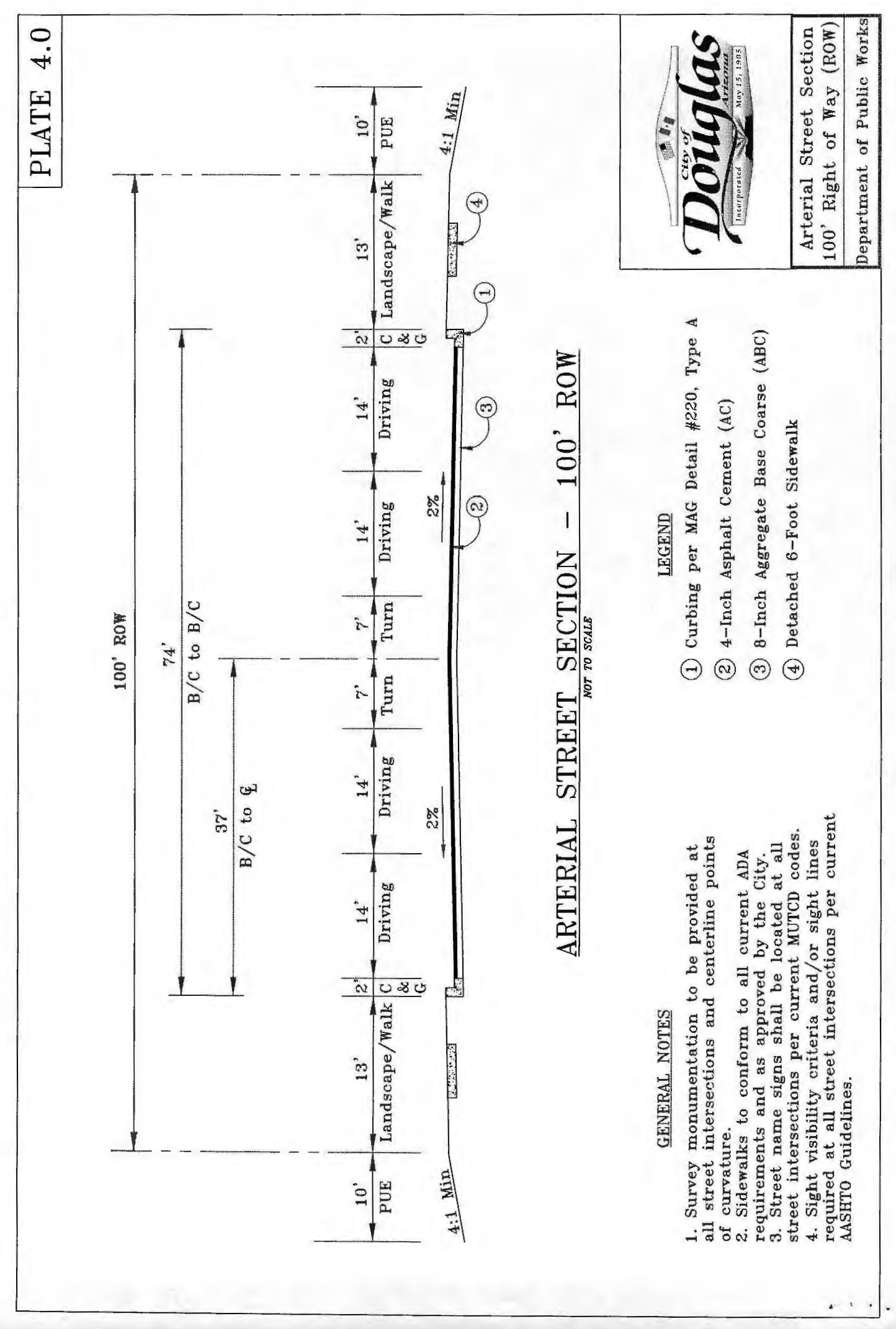
Arterial Major Collector roads shall have a right-of-way of one hundred (100) feet. See Plate 4.0.
b.
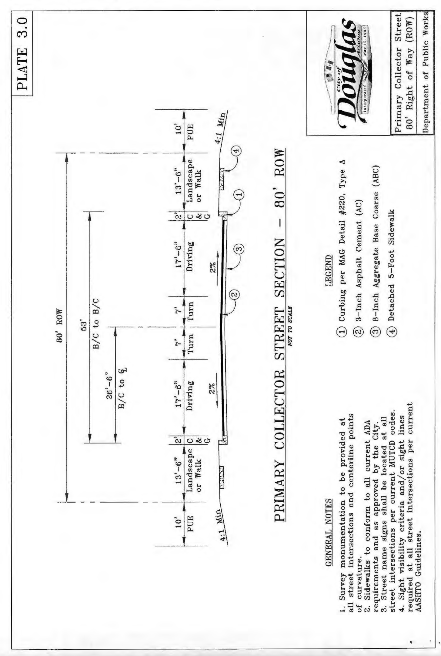
Primary Collector roads shall have a right-of-way of eighty (80 feet). They generally are located on all mid-section lines. See Plate 3.0.
c.
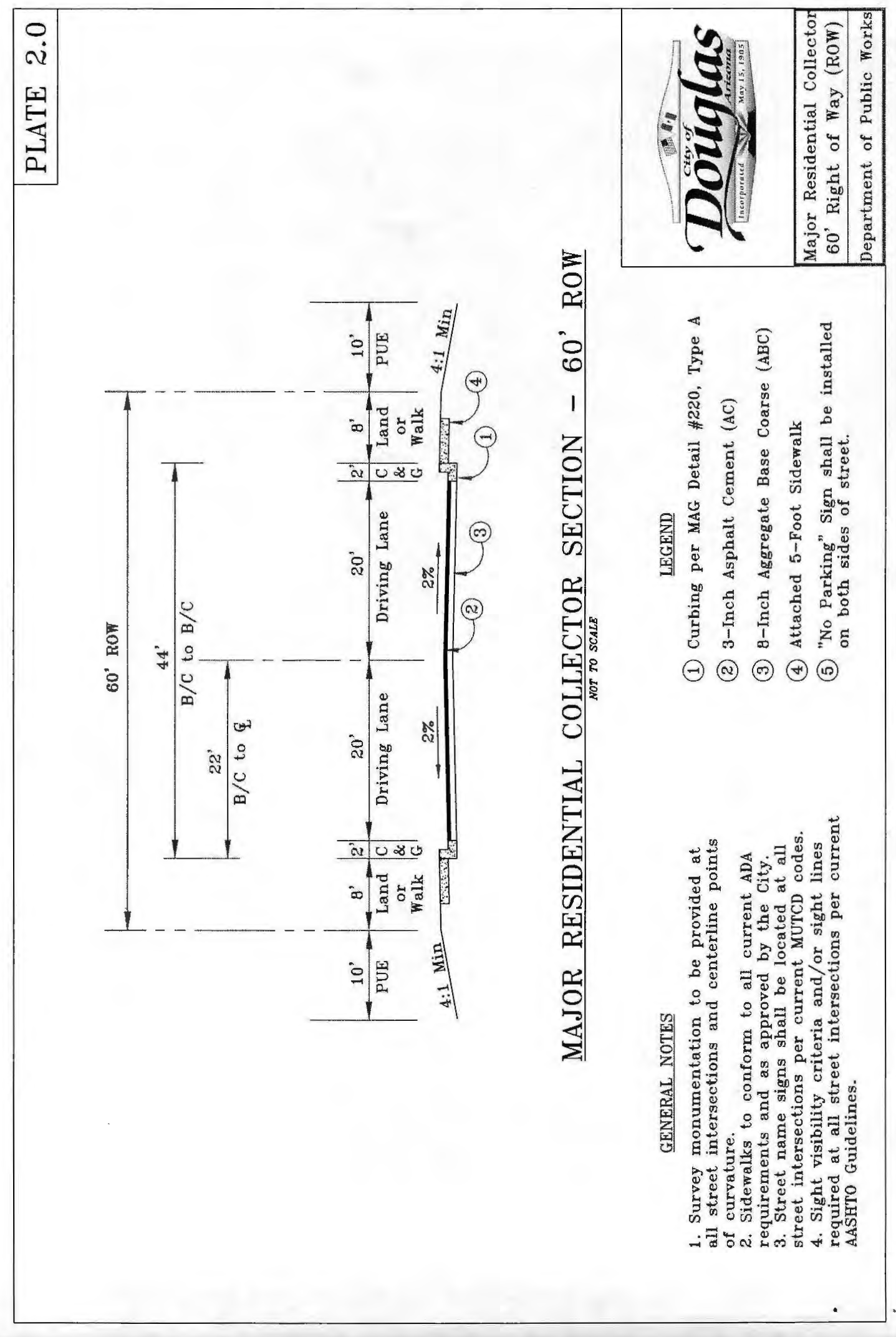
Subdivision entrance roads shall have a right-of-way of sixty (60) feet. See Plate 2.0.
d.
Local Streets:
1)
Serving single-family residences only, fifty (50) feet. See Plate 1.0.
2)
Serving multi-family, commercial or industrial frontage, sixty (60) feet. See Plate 2.0.
3)
Cul-de-sac streets shall terminate in a circular right-of-way fifty (50) feet in radius with an improved traffic turning circle at least forty five (45) feet in radius; or, where extreme conditions justify, the P & Z Commission may approve an equally convenient form of space. Cul-de-sacs shall have a twenty five (25) foot minimum radius for property line return.
4)
For knuckles the Right-of-way circle shall be a minimum of fifty five (55) feet measured from the P.I. opposite rights-of-way. The adjoining reverse curves shall be a minimum of fifty five (55) feet radius.
e.
For marginal access streets, forty (40) feet in addition to arterial right-of-way.
f.
The maximum length of cul-de-sac streets shall be four hundred (400) feet, measured along the street center line from the intersection of right-of-way lines to the extreme depth of the turning circle.
g.
Alleys, sixteen (16) feet when there is residential property on both sides or twenty (20) feet when abutting commercial or industrial districts. Alley intersections and sharp changes in alignment shall be avoided, but where necessary, corners shall be cut off ten (10) feet on each side to permit safe vehicular movement. Dead-end alleys shall be prohibited. All "half" alleys shall have a minimum width of twelve (12) feet.
h.
Dead-end streets shall not be approved except in locations designated by the P & Z Commission as necessary for connection to adjacent unplatted land. In any case, a dead-end street serving more than four (4) lots, shall provide by easement a temporary turning circle with a forty (40) foot radius or other acceptable design to accomplish the same purpose.
i.
Right-of-Way setback for curb radius (dimensions in feet):
j.
Sight Visibility: the minimum clear distance available on a roadway and visible to the driver prior to the execution of a turning movement.
3.
Street grades shall be as follows:
a.
Maximum grades:
1)
For arterial routes, as determined by the Public Works Department.
2)
For collector streets, seven (7) percent.
3)
For local streets, ten (10) percent.
b.
Minimum grades, for concrete or asphalt streets with concrete gutters shall be -0.50 percent. Cul-de-sac turnaround: 25% from center point.
4.
Vertical curves shall comply with the following:
a.
For arterial routes, as determined by AASHTO's "Policy on Geometric Design of Highways and Streets" ("Green Book") or other responsible agency.
b.
For collector and local streets, a minimum length of one hundred (100) feet.
5.
The horizontal alignment of streets shall comply with the following:
a.
For arterial routes as determined by AASHTO's "Policy on Geometric Design of Highways and Streets" ("Green Book") and/or as approved by the Public Works Department.
b.
When tangent center lines deflect from each other more than ten (10) degrees and less than ninety (90) degrees, they shall be connected by a curve with a minimum center line radius of five hundred (500) feet for collector streets, or one hundred fifty (150) feet for local streets.
c.
Between reverse curves there shall be a tangent section of center line not less than one hundred (100) feet long.
d.
Streets intersecting an arterial route should do so at a ninety-degree angle or radial to curve. Other street intersections shall be radial or 90 degree ± 15 degrees.
e.
Street jogs with center lines offsets of less than one hundred twenty-five (125) feet shall be avoided, except where special circumstances may justify.
f.
Local streets intersecting a collector street or arterial route shall have a tangent section or center line at least one hundred fifty (150) feet in length measured from the right-of-way line of the major street; except that no such tangent is required when the local street curve has a center line radius greater than four hundred (400) feet measured from a center located on the major street right-of-way line. Local with local.
g.
Street intersections with more than four (4) legs and Y-type intersections with legs meeting at acute angles shall be avoided.
h.
Street line intersections shall be rounded by a circular arc having a minimum tangent length of twelve (12) feet.
i.
Minimum street offset clearance:
j.
The City of Douglas is a PM10 "Non-Attainment area" which requires improvement of all high traffic roads and parking lots and subject to related dust control measures as determined by the Public Works Department.
6.
Minimum back of curb radius:
7.
Minimum centerline curve radius (feet):
a.
Arterial routes: Determined by AASHTO "Green Book" policies and/or as approved by the Public Works Department.
b.
Collector streets: 250 [feet].
c.
Local streets: 100 [feet].
8.
Minimum tangent between reverse curves (feet):
a.
Arterial routes: Determined by AASHTO "Green Book" policies and/or as approved by the Public Works Department.
b.
Collector streets: 250 [feet].
c.
Local streets: 100 [feet]
9.
The maximum block length shall be fifteen hundred (1,500) feet, measured along the center line of the street and between intersecting street center lines, except that in subdivisions where lot areas average one-half acre or more this maximum may be exceeded by five hundred (500) feet.
10.
Monuments.
a.
Monuments shall be per MAG Standard Detail 120-1. Monuments shall be placed on all section and quarter section corners, these shall be a Type "A" survey marker. The monuments shall be set to the City of Douglas datum and as provided by the Public Works Department.
C. - Street Names.
Street names shall be reviewed and approved by the Rural Addressing Division of the Cochise county Planning Department (520/432-9240). See Chapter V for full details. Street names shall be consistent with the natural alignment and extensions of existing names streets, new street names shall not duplicate or be closely similar to any existing street name.
D. - Paving Requirements.
1.
For Development Paving Projects the following minimum paving depths are required:
a.
Arterial Major Collector Roads: 4-inch asphaltic cement (AC)/8-inch aggregate base course (ABC).
b.
Collector Roads: 3-inch AC/8-inch ABC.
c.
Local Roads: 2.0-inch AC/6-inch ABC.
Above are minimum depth requirements.
2.
Soils and materials reports are required to be submitted to the Department of Public Works for review and approval.
3.
For roads where existing paving exists, structural analysis shall be provided with designed roadway improvements to meet the above requirements. Material samples to be taken at a minimum of every 500 lineal feet per travel lane. Chemical composition of the asphaltic concrete shall comply with MAG Requirement, or recommend surface treatment to bring section into compliance. Recommendation to be approved by the Department of Public Works.
4.
Half road improvements to provide a minimum of one travel lane in each direction in addition to two (2) feet curb and gutter. Half road improvements to provide additional two (2) feet of paving on the undeveloped side of the roadway for a total minimum of 26' of asphalt pavement.
5.
All exploratory bore holes in existing pavement shall be patched with hot mix asphalt.
6.
Street sections per approved preliminary plats requirements.
E. - Paving Requirements—Technical Specifications.
1.
City of Douglas Asphalt and Paving Policy:
The City of Douglas is willing under certain circumstances to sell asphalt to residents and contractors within Arizona and a twenty-five (25) mile radius of the corporate limits of the City of Douglas. This willingness stems from (1) the need to support the public good of improving off-street parking opportunities within the above stated area through a reduction of traffic congestion, (2) improving dust control, and drainage control, (3) minimizing erosion, and (4) promoting of vehicle/pedestrian safety. The Mayor and Council must authorize the sale of asphalt of over 200 tons to residents or contractors doing work within a 25-mile radius of the corporate limits of the City, within the United States. Any amount under 200 tons per purchase may be approved by the City Manager until total sales during the prior 12 months to the same person or entity have exceeded 3,000 tons. At that time the Council must approve future requests. The City Manager may authorize up to 200 tons per purchase to the City of Agua Prieta, State of Sonora, or Country of Mexico provided said asphalt is to be used by these public agencies within a 25-mile radius of Douglas. In the event sales exceed 3,000 tons in a 12-month period, the agency's request will be taken to the Mayor and Council for consideration.
Such material sales are authorized only at such time as the asphalt plant is operating and only to the extent that excess material over that needed for City projects can be reasonably produced. All material purchases must be picked up by the purchaser at the City asphalt plant.
The price of the asphalt sold by the City shall be established at the average market price in effect and charged by private enterprises in Cochise County within 10 days of the order for pick up at the place of business of the private enterprise or at a price specified by the Mayor and Council.
There also may be occasions that the City is requested to perform paving services along with the sale of asphalt. This practice will be limited to churches and qualified private non-profit organizations or corporations operating within the corporate limits of the City of Douglas. This service will be performed only if approved by the Council and is determined to be for the public benefit by providing dust control, improving drainage and minimizing property deterioration, reducing standing water, and creating safer properties by promoting vehicle/pedestrian safety.
A church or qualified non-profit organization or corporation must file a written request with the City Manager for paving or repaving of a lot. The request must include the size of the lot to be paved and the thickness of asphalt needed. Staff will present the cost of the paving when the council considers the request for paving services. The cost will include equipment charges, labor rate, and material. All charges will be charged at a rate as specified by the Mayor and Council at the time of approval. Labor will be charged at the hourly rate of the employee including all fringe benefit costs associated. Material will be charged as described above under material purchases. If the City Council approves the request, the paving will be scheduled into the Department of Public Works paving schedule. Paving will commence within the 120 days of approval as long as City equipment is in proper working order. All payments for material and services must be paid in advance, unless the Mayor and Council or City Manager approves a payment plan. When paving services are provided, the applicant must provide written agreement to pay for all actual increases in component costs for labor, equipment or materials beyond that approved by the Council when those increases occur between the approval date and actual installation date.
Pavement Cuts
There is a five (5) year moratorium on pavement cuts from the time asphalt concrete is placed in that specific location. There will be instances when, due to an emergency situation, the pavement must be cut to preserve the health, safety, and welfare of the general public. In these cases, the Director of Public Works can give approval of such pavement cuts.
This policy is intended to discourage pavement cuts beyond the five-year moratorium. All other options must be considered including but not limited to boring under the street and rerouting around the street.
Prior to any pavement cuts, a right-of-way permit must be obtained from the Department of Public Works.
2.
All work and materials must conform to the current uniform standard specifications and details as published by the Maricopa Association of Governments (M.A.G.) and as amended by the Public Works Department.
3.
The Contractor shall obtain any and all permits required unless otherwise noted. A pre-construction meeting will be mandatory.
4.
The Contractor shall notify the Public Works Department a minimum of forty-eight (48) hours in advance to any construction.
5.
The Contractor shall be responsible for blue stake and locating underground utilities. The Contractor shall be responsible for any and all damage that may be incurred to the utilities and be liable for any repair costs including accidental costs.
6.
The Project/Design Engineer shall certify that he has contacted all utility companies and has transferred, according to information furnished by said utility companies prior to plan approval, all existing and/or proposed utility lines and all existing and required right-of-way and easement lines. However, the Contractor is solely responsible for determining the exact location of all existing utilities in the immediate area prior to the beginning of construction.
7.
One set of stakes will be furnished by the Contractor for the curb and gutter, sidewalk, subgrade and ABC. All additional staking will be charged to the Contractor. Forty-eight (48) hours advance notice is required for staking.
8.
All manhole frames and covers, cleanouts and water valve boxes and covers shall be adjusted to finish grade per MAG Std. Detail No. 270 and Spec. No. 345.
9.
Construction of surface improvements shall not begin until conflicting underground utility construction is completed and service connections to all platted lots have been adequately extended.
10.
All underground utilities and street surfacing shall be constructed and completed prior to the issuance of any building permits.
11.
Developer, Contractor and Suddivider shall provide to all the underground utilities a certificate of grade prior to the commencement of utility trenching to ensure that the roadway subgrade is within acceptable finish grade that meets or exceeds the minimum coverage requirement set by each underground utility. The certification of grade shall read as follows "I, the undersigned, hereby certifies to the individual members of the Douglas Infrastructure Group (DIG), that I, on behalf of the above property owner(s), surveyed and marked the property corners and/or utility easements as required along the route of the proposed DIG facility installation for the xxxxx project and have found the existing ground to be within six inches of final and finish grade where the DIG trench and all related DIG equipment are to be placed".
12.
Damaged asphalt and/or displaced concrete curb, gutter, sidewalk or driveway slab that is within the right-of-way shall be replaced or repaired as directed by the City before final acceptance of the work by the City.
13.
Acceptance of the completed right-of-way improvements shall not be given until:
a.
Reproducible "as-built record drawings" have been submitted by a registered professional engineer and accepted by the Public Works Department. When the Public Work Department provides inspection, the registered engineer shall certify that staking was performed under his supervision and the "project record" elevations and dimensions shown on the plans are correct as stated.
b.
The Project/Design Engineer or registered surveyor shall certify in writing as to the accurate location of all survey monuments.
c.
All improvement work is completed to the satisfaction of the Public Works Department including utility adjustments, survey monuments, sign bases, parkway grading and any repairs or replacements.
13.
All actual points of pavement matching and/or termination shall be determined in the field by the Public Works Department.
14.
A copy of all test reports shall be sent to the Public Works Department.
15.
Subgrade and paving operations shall not begin until all utility frame and cover locations have been properly referenced to facilitate adjustments.
16.
All water service meter boxes shall be set to have the top of box elevation match the top of sidewalk elevation.
17.
The developer, owner or Public Works Department shall monitor and enforce as-builts of all new concrete curb, gutter, valley gutter and other drainage control structures before any paving operations are to begin. Elevation shall be checked on substantial conformance for proper drainage as designed. Any discovered deficiencies shall be corrector at the Contractor's expense. After the new pavement is constructed, the Contractor shall provide for a water test under City inspection to verify proper and adequate drainage as designed. Any deficiencies shall be corrected at the Contractor's expense prior to City acceptance.
18.
Any sleeving done under new streets shall be done with Sch. 80 PVC conduit.
19.
For utility and trench related work, all compaction to be Type 1. All streets and related work shall conform to MAG Specification part 300. All tests shall be conducted by a certified geotechnical testing lab, provided for the owner/developer or Project/Design Engineer, at their cost. Sufficient testing shall be done to adequately verify the required densities and tolerances. The location and frequency of tests shall be as directed by the City and specific public utility specifications. The owner/developer shall have the geotechnical testing lab retained along with a written confirmation, submitted to the City, prior to issuance of the R.O.W. engineering permit and approval from the specific public utility.
20.
The Contractor shall be responsible for dust control related to the project construction and shall take whatever means necessary to control any abnormal conditions.
21.
The Contractor shall be responsible for constructing and maintaining temporary construction access ramps/entrances per City requirements as needed.
22.
Subgrade and paving operation shall not begin until all utility work is complete including backfill operations.
23.
The Contractor shall be responsible for adequate barricading and traffic control, as approved by the City, where the construction of the new improvements is adjacent to or connecting to any existing facilities. The Contractor is required to submit a traffic control and barricade plan to the City, for approval, before that particular work can take place. A haul route plan is also required for dirt material import or export.
24.
Contractor shall submit a Notice of Intent (NOI) and follow the City's current Storm Water Pollution Prevention Plan (SWPPP) Rules & Regulations.
25.
Contractor responsible for maintaining proper and adequate access roads inside and throughout the parcel allowing for inspection accessibility. This includes grading, gravel fill, trench plates and dust control.
26.
The Contractor shall be responsible for daily and final clean-up operations of adjacent, existing paved streets used by construction traffic. This work includes street sweeping, power broom and water as needed.
27.
Asphalt design mix to use 5.0% oil content and 2.0% cement content. Contractor to submit design mix to Public Works Department.
28.
Correction of concrete and asphalt deficiencies:
a.
Inverse flows in concrete curb and gutter and valley gutter aprons: to be replaced. No grinding allowed.
b.
Incorrect elevations with correct flow direction: flat grinding may be allowed, but no slot grinding.
c.
Low spots in asphalt: tack and spin patch with cement based AC, D12 or ⅜" aggregate mix, no c-¾" mix. Slurry seal may be required.
d.
High spots in asphalt: grinding or milling, ¾" minimum with tack and AC patch, cement based. Slurry seal may be required.
e.
Re-heating or "burning" of asphalt not allowed.
f.
Asphalt replacement: sawcut and remove with like replacement of AC mix, asphalt thickness or replacement section to be an additional one (1) inch. Recompaction of ABC subgrade required. Slurry seal may be required. Tack required.
g.
Curb and gutter and valley gutter cracks: greater than ⅛" to be removed and replaced. Sawcut and epoxy grout patch may be allowed depending on location and severity.
h.
Curb and gutter and valley gutter cracks: less than ⅛" to be patched with epoxy grout.
i.
Apron cracks: apron to be replaced.
j.
Sidewalk cracks: sidewalk to be replaced.
k.
Asphalt gaps and seams: slurry seal or micro seal. Milling and A.C. patch may be required.
29.
Fiber-mesh required for concrete aprons and valley gutters.
30.
Contractor to provide all street signage as required by the Public Works Director.
31.
Substantial completion and final inspections required.
A. - Grading Plan Requirements.
1.
Earthmoving permit issued by City of Douglas Public Works Department.
B. - Grading and Drainage Requirements—Technical Specifications.
1.
A grading permit is required by the City Public Works Department. Cochise County will issue all related dust and haul route permits.
2.
Excavating Contractor must give location for wasting excess excavation and a letter from owner giving permission for dumping prior to starting on-site construction.
3.
Public Works Department shall be notified at least forty-eight (48) hours prior to any on-site construction activity at telephone (520) 805-4077; ext. 406.
4.
Staking for pad and/or finish floor elevations is the responsibility of the developer and his engineer. Developer's engineer shall submit certification of constructed building pad elevations prior to request for final inspection.
5.
A separate permit is necessary for any off-site construction.
6.
A grading and drainage plan shall be on the job site at all times. Deviations from the plan must be preceded by an approved plan revision conducted and approved by the Public Works Department.
7.
Drywells must be drilled a minimum of five (5) feet into permeable porous strata or percolation tests will be required. Inspection is required for the drywells before backfill and to verify installation of drain pipes and appurtenances before placement of rock.
8.
Grading and drainage plan approval includes: the construction of all surface improvements shown on the approved grading and drainage plan, including but not limited to, retention areas and/or other drainage facilities, drainage patterns, retaining walls, walls, required drainage structures, subgrade for curb and gutter, subgrade for asphalt pavement and building floor elevations.
9.
Contractor shall provide a level bottom in all retention basins at elevations as shown on the plans. Retention basins side slopes shall not exceed 4:1 on private property unless noted otherwise on the plans.
10.
No underground or overhead utilities shall be designed and constructed within the limits of any retention, detention stormwater facilities.
11.
Contractor is responsible for blue stake locating and confirming depths of all existing utility lines within proposed retention basin areas. If the basin cannot be constructed as per plan because of conflict with underground utilities, the Contractor should request modification of basin configuration by plan revision.
12.
All drainage protective devices such as swales, interceptor ditches, pipes, protective berms, concrete channels or other measures designed to protect homes from storm runoff must be completed prior to any structure being built.
13.
Soils compaction test results must be submitted to the Public Works Department for building pads that have one (1) foot or more of fill material indicated. This information must be supplied prior to request for final inspection.
14.
Clearance for occupation of any building is denied until grading and drainage improvements are completed.
15.
Temporary drainage control measures may be required during and after construction until final lot build-out in accordance with the approved plans and in accordance with any established or required best management practices (BMPs) as part of the national pollution discharge elimination system (NPDES) permit requirements. It is the owner/Contractor's responsibility to meet all established requirements.
16.
Contractor is responsible for "ramping" or protecting all existing concrete/asphalt. In addition, Contractor must provide for proper gutter drainage flow under any ramps by using steel or PVC (schedule 80) pipe. Ramps to be constructed of ABC or asphalt, not dirt. Ramps shall extend a minimum of twenty-five (25) feet into the parcel and wide enough to handle all construction traffic, sixty (60) feet minimum.
17.
All grading behind sidewalk or curb and gutter to be left down 3" below top of concrete for new and existing areas, all locations.
18.
All construction access locations to the parcels are subject to Public Works Department approval.
19.
Contractor responsible for maintaining proper and adequate access roads inside and throughout the parcel allowing for inspection accessibility. This includes grading, gravel fill, trench plates and dust control.
20.
The Contractor shall be responsible for dust control related to project construction and shall take whatever means necessary to control any abnormal conditions. An approved dust control permit will be required at all times.
21.
The Contractor shall be responsible for daily and final clean-up operations of adjacent, existing paved streets used by construction traffic. This work includes street sweeping, power broom and water as deemed necessary to maintain a clean public right of way.
22.
The Contractor is required to submit a traffic control and barricade plan to the City, for approval, before that particular work can take place. An approved haul plan is also required for dirt material imported or exported to or from the project site.
23.
The Contractor shall be responsible for blue stake and locating underground utilities. The Contractor shall be responsible for any and all damage that may be incurred to the utilities and be liable for any repair costs including accidental costs. The Contractor and/or developer will be responsible for contacting the owner of each various utility and facility with which there are conflicts with the new construction and making all necessary arrangements with the owner for relocation or abandoning the utility or facility as required by its owner.
24.
Damaged asphalt and/or displaced concrete curb, gutter, sidewalk, or driveway slab that is within the right-of-way shall be replaced or repaired as directed by the City before final acceptance of the work by the City.
25.
Grading Contractor responsible for compaction of perimeter fence wall foundations, 90% density required. Developer/owner or engineer to stake locations. Certified geotechnical testing lab, provided for by the developer/owner or engineer, must be retained for all testing.
A. - Street Light Pole Spacing and Height Requirements.
1.
All poles and mast arms shall be steel construction with a galvanized finish, gray color (except for the architectural style as noted above).
2.
Pole bottom shall be uniformly half lap taped with Scotch 50 corrosion protection tape or approved equal, up to 2" below hand hole.
3.
All street light design plans including layout and construction shall be prepared and sealed by a registered electrical engineer. Construction permits shall not be issued until the design plans and Contractor submittals have been approved by the City and Arizona Public Services (APS).
4.
Contractors shall submit technical material specifications on all items listed above for City and APS review and approval.
B. - Street Light Luminaire Requirements.
1.
All luminaries to be "Cobra" head style, gray color (except for the architectural style as noted above) or equivalent. APS approval required.
2.
Luminaires to be fuseless with photoelectric control.
3.
Contractors shall submit technical material specifications on all items listed above for City and APS review and approval.
C. - Construction Guidelines.
1.
Unless otherwise directed, installation of the poles, mast arms, luminaries, j-boxes and other related appurtenances shall be in accordance with current APS construction guidelines as applicable.
D. - General.
1.
Streets Backfill requirements:
a.
Longitude trench backfill in new or existing arterial roadways, or adjacent to existing roadways, or within the ultimate R.O.W., and future roadways shall require full depth approved ABC material or 100% one sack ABC slurry as directed by the City/APS. Trench compaction in existing roadways shall be by an approved mechanical method with backfill materials lifts no greater than twelve (12) inches loose. Refer to MAG Sec. 601.4.
b.
Transverse trench backfill in existing roadways or new arterials shall require 100% one sack slurry as directed by the City/APS.
c.
Bedding, shading and backfill shall be used and placed and compacted in accordance to the specifications provided by the public utilities.
d.
Per MAG Sec. 601.4, compaction by water jetting or trench flooding is only allowed for trench backfill and compaction in new, local and collector street roadways within new developments. Backfill material lifts for water jetting or trench flooding shall not exceed four (4) feet (loose) in depth. Water consolidation shall not be allowed for backfill and compaction of water line trenches in or adjacent to existing roadways and new arterial street roadways.
2.
It is the sole responsibility of the Contractor to obtain all applicable permits issued by the City with APS approval.
3.
Submittals to the City/APS for street lights. Technical data on the following items shall be submitted to the City/APS for review and approval prior to construction including, but not limited to, the following:
a.
Poles, mast arms, fuse holders, conduit, conductors, photocells, concrete footings, "J" boxes, luminaries, etc.
4.
SERVICE: The Contractor shall furnish and install conduit, trench and backfill from the underground junction box to the pole and to the point of delivery as determined by the serving utility company. The Contractor shall coordinate with the serving utility company for routing of conduit and construction requirements.
5.
CONDUIT: Conduit shall be installed at the depth specified by APS. Conduit between the pole and adjacent J-box shall be one (1) inch carflex liquid tight flexible nonmetallic conduit or APS approved equal. Conduit must be UL rated and suitable for underground use.
6.
LIGHT POLE IDENTIFICATION: The Contractor shall furnish and install a number on each light pole. Street light pole identification and specifications will be provided by APS.
7.
RESTORATION: It is the Contractor's responsibility to restore all property, landscaping, paving, and driveways that are disturbed during street light construction to their original condition in conformance with M.A.G. Specifications Section 107.9.
8.
PERFORMANCE: Prior to acceptance, the Developer shall energize and operate the entire roadway lighting system, from sunset to sunrise for two (2) consecutive days without interruption or failure. If a lamp or ballast should fail, it shall be immediately replaced.
9.
Unless otherwise specified, no street light pole shall be located closer than 6'-0" from face of curb for all streets. Shifting of pole locations to avoid minor conflicts in the field shall be limited to a maximum of ten (10) feet; this includes sidewalks, channels, other utilities, driveways, fences, etc. City/APS approval is required and any approved shift requires proper "As-Built" documentation.
10.
Street light conductor trenches shall not be backfilled until inspected and approved by City/APS inspectors.
11.
Backfill around direct buried poles shall be ABC material compacted in lifts using pneumatic or vibratory equipment. Compaction shall be to 90% minimum standard proctor. Density as defined by ASTM D-2922 and D-3017.
12.
Arterial roads, roads of regional significance, commercial collectors and all other public rights of ways shall use the architectural style steel pole, shoebox luminaire dark bronze in color, pedestal mount with a luminaire mounting height of forty (40) feet and/or equivalents as approved by APS and accepted by the City.
Contractors shall submit technical material specifications on all items listed above for City and APS review and approval. A Structural Engineer registered in the state of Arizona shall seal all structural pole calculations. Wind speeds of 100 MPH shall be used in all the pole structural calculations. Arterial streets without medians and collector streets shall have a staggered spacing while local streets shall have single sided spacing as listed in this Chapter, section A.
13.
Any variance to the approved spacing shall require a new design accompanied with point-to-point lighting calculations at ten (10) foot intervals indicating maintained foot-candle levels and uniformity ratios between luminaries and across the width of the roadway for approval by the City/APS.
14.
All poles and mast arms shall be steel construction with a galvanized finish, gray color as approved by APS.
15.
Embedded pole bottoms shall be uniformly half lap wrapped with Scotch 50 corrosion protection tape or approved equal, up to 2" below hand hole.
16.
All street light design plans including design layout and construction shall be prepared and sealed by a registered electrical engineer in the state of Arizona. Construction permits shall not be issued until the design plans and Contractor submittals have been approved by APS.
17.
No Certificate of Occupancy shall be approved by the City until all streetlights are energized, fully operational and As-Builts received.
18.
Meandering sidewalks must be constructed in such a manner as to clear street light locations.
19.
Luminaires (with photocells) and mast arms shall be of type approved by the APS. Coordinate with the APS for a list of acceptable luminaire manufacturers. Ballast shall be autotransformer, constant wattage, high PF (90% min.) with a multitap ballast and starters must be plug-in types per APS specifications.
20.
All Points of Curvature (P.C.s) and Points of Tangency (P.T.s) to be stationed off of centerline. Refer to civil plans for exact stationing of all applicable P.C.s and P.T.s.
21.
All streetlights to be stationed off of centerline unless otherwise noted.
22.
Label specific locations, sizes, and dimension from center line and/or monument line the following:
a.
Existing and proposed underground utilities.
b.
Existing and proposed overhead utilities.
c.
Face of curb
d.
Width of sidewalk.
e.
Edge on any PUE.
f.
Edge of right-of-way.
g.
Edge of pavement.
23.
Street light poles shall be a minimum of six (6) feet from the edge of a driveway wing.
24.
Maintain a minimum five (5) feet of clearance between fire hydrants and street light poles.
25.
Residential light poles shall be placed on lot lines whenever possible.
26.
Light poles shall not be placed in the radius of a corner at intersections unless otherwise specified.
27.
It is the responsibility of the Developer to assure that the area adjacent to an electric utility company's transformer is kept clear of all the above ground obstructions for a distance of twelve (12) feet in front of and one (1) foot each side of the transformer.
28.
Street lights shall be installed in the right-of-way unless approved otherwise by the City.
29.
Intersection lights should be at least equal the sum of the values recommended by IES for each street that forms the intersection. Photometric lighting analysis shall be provided to show that this requirement is satisfied.
30.
Roadway classifications are as follows:
31.
Classification shall be determined by the City of Douglas.
32.
Lighting analysis shall be required for street dimensions and/or light pole spacing that vary from standard roadway widths and spacing.
33.
Future street light locations shall be shown on the street light plans and as approved by the City.
34.
All finished pole foundations and pull boxes shall be at sidewalk grade unless otherwise noted.
35.
Lighting project shall be fully identified in the field by Blue Stake before any digging can begin.
36.
The following information shall be required on each set of street light plans:
a.
The following general note: All construction shall be in accordance with the City of Douglas Public Works Department and APS.
b.
Vicinity Map.
c.
Legend.
d.
Construction Notes.
e.
General Notes as required.
f.
Project Title.
g.
Blue Stake caution note, and blue stake number 1-800-782-5348.
37.
It is the Developer's responsibility to engage a surveyor to stake all proposed light pole:
WE STILL NEED THE JOINT TRENCH DETAIL, COLOR AND INSTALLATION OF TRACER WIRE SPECIFICATION, WIRE IN THE BOX W/COLOR
E. - APS Specific Construction Requirements.
1.
Installation and materials shall be per City of Douglas and APS street lighting standards and specifications.
2.
The Contractor shall coordinate all work with APS and the City prior to start of any construction.
3.
All conduit, trench and backfill from junction box at pole to utility point of services shall be per APS requirements. Trenches shall not be backfilled until inspected and approved by an APS offsite inspector.
4.
An underground junction box (provided by APS) and a 5/8" x 8' ground rod shall be installed adjacent to each street light pole. A #6 copper bond wire from pole ground lug to ground rod shall be installed and connected.
5.
Luminaries (with photocells) and mast arms shall be of type approved by the City. Coordinate with the City for list of acceptable luminaire manufacturers. Ballast shall be autotransformer, constant wattage, high Power Factor (90% min.) with a multitap ballast. All submittals shall be approved by the City and APS.
6.
Direct bury poles shall be buried with ABC material, backfill around pole, and of standard type approved by the City. An APS approved underground junction box; ground rod and fuse kit shall be installed adjacent to each pole. The Contractor shall coordinate with APS for incoming power connections.
A. - Manual on Uniform Traffic Control Devices (M.U.T.C.D.).
1.
Sign requirements, guidelines, warranties shall be in accordance with the M.U.T.C.D. most current addition.
2.
All signs shall conform to the M.U.T.C.D. and shall be made from .080 thick aluminum.
3.
Any information not found in the following pages can be found in the M.U.T.C.D. and any work performed and materials used shall conform to M.U.T.C.D. requirements.
B. - Sign Post and Extensions.
1.
Sign posts and extensions shall be galvanized U-CHANNEL type having weight of two (2) pounds per foot and shall be driven into the ground a minimum of thirty-two (32) inches. Extensions may be used if needed to bring the sign up to proper height as described in the section on "Height Requirements".
C. - Street Names.
1.
All proposed street names for new subdivisions must be submitted, reviewed and approved by the Rural Addressing Division of the Cochise County Planning Department (520/432-9240). The Rural Addressing Division (RAD) requests applicants to submit a map showing the platted streets with the proposed names. New road names shall have directionals and suffixes but with no punctuation in them. RAD no longer accepts new road names that begin with CALLE, PLAZA, CAMINO, VIA or DE LA. All new roads that align with existing roads shall have the same name.
D. - Street Name Signs.
1.
Street name signs shall be made from eight hundredths (0.080) of an inch thick aluminum and have a width of six (6) inches and length determined by need. They shall be rectangular in shape and have radiused corners. Both sides shall have white engineer grade reflective letters on a green engineer grade reflective background. Lettering on street name signs shall be at least four (4) inches high. Supplemental lettering to indicate the type of street (e.g., street, avenue, road, etc.) or the section of the City (N.S.E.W.) may be smaller in lettering, but must be at least two (2) inches in height and must be made of the same engineer grade reflective material.
E. - Street Name Sign Mounting Hardware.
1.
Street name mounting hardware shall be made of a rust proof alloy and shall have a minimum blade holder length of five (5) inches and have a minimum of two (2) allen-head set screws in each blade holder. All hardware must be of proper type for use with U-CHANNEL type posts and be compatible for use with eight hundredths (.080) of an inch thick street name signs.
F. - Height Requirements.
1.
In business, commercial or residential districts where parking and/or pedestrian movement is likely to occur or where there are other obstructions in view, the vertical clearance from the top of the walking surface to the bottom of the sign shall be no less than seven (7) feet. The height to the bottom of a secondary sign mounted below another sign (other than a street name sign) may be one (1) foot less than the seven (7) foot specified above.
G. - Horizontal Clearance in Urban Areas.
1.
All signs shall have a minimum horizontal clearance from the edge of sign to the outside face of the curb of at least two (2) feet or if no curb exists it shall be at least two (2) feet from the edge of the adjacent pavement. All signs shall be placed so as not to interfere with the flow of pedestrian movement.
A. - Design.
1.
Signal design requirements and guidelines shall be in accordance with the Manual on Uniform Traffic Control Devices (M.U.T.C.D.), Chapter 4 (2003 Edition).
B. - City Traffic Signal Definitions, Warrants and Design References.
1.
Definition.
A traffic control signal (traffic signal) shall be defined as any highway traffic signal by which traffic is alternately directed to stop and permitted to proceed.
Traffic shall be defined as pedestrians, bicyclists, ridden or herded animals, vehicles, streetcars, and other conveyances either singularly or together while using any highway for purposes of travel.
Standards for traffic control signals are important because traffic control signals need to attract the attention of a variety of road users, including those who are older, those with impaired vision, as well as those who are fatigued or distracted, or who are not expecting to encounter a signal at a particular location.
2.
Engineering Studies. The selection and use of traffic control signals should be based on an engineering study of roadway, traffic, and other conditions. A careful analysis of traffic operations, pedestrian and bicyclist needs, and other factors at a large number of signalized and unsignalized locations, coupled with engineering judgment, has provided a series of signal warrants that define the minimum conditions under which installing traffic control signals might be justified. Engineering judgment should be applied in the review of operating traffic control signals to determine whether the type of installation and the timing program meet the current requirements of all forms of traffic.
3.
Warrants. An engineering study of traffic conditions, pedestrian characteristics, and physical characteristics of the location shall be performed to determine whether installation of a traffic control signal is justified at a particular location.
The investigation of the need for a traffic control signal shall include an analysis of the applicable factors contained in the following traffic signal warrants and other factors related to existing operation and safety at the study location:
Warrant 1, Eight-Hour Vehicular Volume.
Warrant 2, Four-Hour Vehicular Volume.
Warrant 3, Peak Hour.
Warrant 4, Pedestrian Volume.
Warrant 5, School Crossing.
Warrant 6, Coordinated Signal System.
Warrant 7, Crash Experience.
Warrant 8, Roadway Network.
The satisfaction of a traffic signal warrant or warrants shall not in itself require the installation of a traffic control signal.
4.
Design References.
a.
Traffic Impact Analysis. A Traffic Impact Analysis in accordance with the Arizona Department of Transportation (ADOT) Traffic Impact Analysis criteria shall be submitted for all new developments generating one hundred (100) or more peak hour trips. Use the most current Version of Institute of Transportation Engineers (ITE) Trip Generation manual to determine peak hour trip estimates.
b.
Signal Modifications. Signal modifications that are a result of street widening or recommended in the Traffic Impact Analysis related to the development are the responsibility of the Developer.
c.
Signal Conduit. Signal conduit with pull boxes shall be provided at all major arterial, minor arterial and collector street intersections as shown in ADOT's Specification and Standard Drawings.
d.
Specifications and Details. Traffic signals shall be designed in accordance with the ADOT Traffic Signals and Lighting Specification and Standard Drawings.
5.
Traffic Signal Equipment.
a.
Traffic signal poles and hardware shall conform to the ADOT standards and shall be approved through the Electrical Equipment Submittal process.
b.
Traffic signal cabinets and controller/electronic equipment shall be selected from the City of Douglas approved Traffic signal cabinets and controller/electronic equipment list. Traffic signal cabinets and controller/electronic equipment shall be approved through ADOT's Electrical Equipment Submittal process.
A. - Traffic Control Devices.
1.
Traffic control, sign, barricades and pavement markings shall be in accordance with the Manual on Uniform Traffic Control Devices (MUTCD) as revised. Street and lane closures shall also be in accordance with the MUTCD as revised. When any existing traffic control signs, barricades, guard rails, traffic signal facilities and equipment are to be removed or replaced, care shall be taken to salvage such facilities and equipment.
B. - Traffic Signs and Pavement Markings.
1.
All new developments shall provide the required traffic control signs, street name signs, sign posts and pavement markings on all streets and intersections as outlined in the MUTCD and approved by the Public Works Director. The Contractor will install the signs, posts and markings at the developer's expense. Final Certificate of Completion will not be released and streets will not be opened to the public until all signs and markings have been installed per approved signing and striping plans.
2.
A Pavement Signing and Striping Plan shall be submitted to the Public Works Department and approved through the plan review process. All required signage will be shown on the plans (i.e., call out required stop sign with sign pole base upon entry to an existing arterial and/or collector street). It is the Design Engineer's responsibility to include all signing and striping to complete a safe design.
3.
All signs and sign posts shall conform to Chapter V and MUTCD standards and be installed accordingly.
4.
The Pavement Signing and Striping Plan shall also include specifications and locations of all Raised Pavement Markers (RPM's) per MUTCD and ADOT requirements.
C. - Traffic Control Plan.
1.
A Traffic Control Plan will be reviewed and approved by the Public Works Department prior to commencement of construction. The plan shall indicate the construction duration and schedule and the hours of operation for the project. The plan shall show the proposed work location area in detail and describe the traffic routing, traffic control devices, signage and construction traffic routing proposed. Additional information and stipulations may be required by the Department on a case by case basis. This requirement is in addition to the submission of a Traffic Control Plan prior to the start of construction.
a.
A traffic control plan shall be submitted to the Public Works Department a minimum of 72 hours (3 working days) prior to any proposed partial or complete street or alley closure. The Department will review all Traffic Control plans prior to Traffic Control plan approval and commencement of work by the permittee. Work shall not commence on the portion of the project requiring street barricading until approval has been obtained in writing from the Department.
b.
Work in/on residential streets typically do not need a separate traffic control plan provided all signs, barricades and other necessary traffic control devices are placed in accordance with Department requirements and the Manual Uniform Traffic Control Device (MUTCD) standards.
c.
Design and implementation of the Traffic Control plan shall be performed by a well-trained and knowledgeable individual assigned the responsibility for traffic control devices at work sites. This individual must be ATSSA (American Traffic Safety Devices Association) certified.
d.
The traffic control plan shall include the identification and location of all barricades and signs, the hours of operation for the project, the construction duration and schedule, location of Variable Message Signs or arrow boards, bus stop signs, advisory signs for relocation of bus stops, detour plans, relocated traffic control signs and the project identification signs. Construction project signage shall be posted by the permittee.
e.
A copy of the approved traffic control plan shall be available at the job site at all times for the duration of the project.
2.
It is unlawful for any person or entity to install on any street or sidewalk on any City street a traffic control device, barricade or any other item interfering with the movement of vehicular or pedestrian traffic without first having obtained an individual permit or approved construction plans and approved traffic control plan issued by the Director of Public Works or their designee.
3.
The Director of Public Works or their designee may remove summarily without notice from any street or sidewalk any traffic control device, barricade or other item interfering with the movement of vehicular or pedestrian traffic that has been placed in such a location without an individual permit or approved construction plans.
4.
Traffic lanes shall normally be 12 feet in width and have safe operating speed of 25 miles per hour. When traffic control plans call for an asphalt or oil paved detour, the contractor shall provide and maintain it in a safe drivable condition. When traffic is diverted from the pavement, the contractor shall provide a suitable graded surface with proper dust control.
5.
Except under emergency conditions, streets shall not be closed for construction activity unless prior approval is obtained from the Public Works Director or their designee.
D. - Barricades.
1.
All new developments shall provide a typical end of road marker at all dead ends and incomplete streets. The end of road markers shall be nine (9) red reflectors, each with a minimum dimension of three (3) inches, mounted symmetrically on an 18-diamond back panel. Five (5) or more markers shall be used at the end of the roadway. The minimum height of the marker shall be four (4) feet.
2.
With approval by the Public Works Director, barricades installed by phased construction may be relocated within the same development if the condition of the barricades is restored.
3.
Barricades shall be set one (1) foot inside the subdivision being developed. The pavement should stop short of the barricade.
A. - General.
1.
These standards establish a uniform engineering approach for determining water demand and minimum criteria for design of water distribution mains. The standards are structured to accommodate designers who are preparing construction plans for private development. It is not intended to provide standards that are all encompassing or to be substituted for innovative design. The user of sound engineering principles is encouraged to develop public water system designs that are not only economical to construct but are economical to operate and maintain.
2.
New public water distribution facilities shall be designed in accordance with the City of Tucson Standard Specifications and Details (2001 Edition), Maricopa Association of Governments (MAG) Standard Specifications and Details, American Water Works Association Standards, Arizona Department of Environmental Quality Bulletin No. 10 and/or A.A.C. R18-4.
B. - Water Demands.
1.
Water main design shall be based on maximum day flows, as listed in Table III, plus fire flows. Appurtenances (booster, reservoirs, etc.) shall be designed for peak hour of the maximum day with provisions for fire flow and emergency flows as required. The peak hour is one point seven (1.7) times the maximum day demand. System pressures should be maintained between sixty (60) and one hundred (100) psi for maximum day velocity and should not exceed five (5) fps or a head loss of ten feet per 1,000 feet (10 ft./1,000 ft.), whichever is limiting.
2.
If a proposed development does not fit one of the above areas, the maximum is not identified in Table III - Maximum Day Flows will be calculated at two hundred twenty (220) gallons per person per day.
3.
Population Density: The Population density for less than five (5) dwelling units per acre is three point two (3.2) persons per unit and two (2) persons per unit for population densities of five (5) or more dwelling units per acre.
4.
Prepare pipe network models showing that the following are met.
a.
Maximum daily flow demand plus fire flow with minimum residual pressure of twenty (20) psi throughout the system.
b.
Peak hourly flow with minimum residual pressure of forty (40) psi throughout the system.
C. - Design Criteria.
1.
Pipe Sizing.
a.
The minimum standards for Water Distribution pipe sizing as follows:
b.
Mains designed as single feed systems with fire hydrants shall be a minimum of eight (8) inch diameter. An eight (8) inch diameter main configured as a looped system with two (2) feeds can serve up to six (6) fire hydrants. Fire hydrant source water shall be from a minimum eight (8) inch diameter main.
c.
Eight (8) inch diameter water main is permitted only in cul-de-sacs of three hundred fifty (350) feet or less with fewer than ten (10) services.
2.
Pipe materials shall be as specified in the City of Tucson Standard Specifications and Details (2001 Edition) with the following exception: To provide reliable water service, and minimize City maintenance activities on private property, public piping within easements (outside dedicated streets), normally located in shopping centers, industrial developments and commercial/apartment complexes, shall be ductile iron or PVC (AWWA C-900, class 150). All service piping for meters, three (3) inch and larger, shall be ductile iron. PVC greater than twelve (12) inch shall be C-900/Class 150 with mechanical joint fitting.
3.
Pipe locations, where possible, shall follow the standard locations in streets established by the Public Works Director. A six (6) foot minimum horizontal separation from any parallel underground utility is required. In all major streets and other active utility corridors a utility conflict review will be required with approval by the Public Works Director as well.
4.
Fire line (private hydrants and building sprinkler) connections may be part of the mainline water construction plan if properly approved drawings for these services are available at the time of plan review.
5.
Backflow Prevention. Back-flow prevention may be required on potable water supply lines to prevent the possibility that the main potable water supply may become polluted or contaminated. This type of protection is called containment or secondary protection and is placed as close as possible to the water meter for domestic, landscape or any other use, and near the property line for a fire sprinkler system. If water is used for anything other than bathroom and drinking fountains a back-flow preventer may be required before a certificate of occupancy is granted.
a.
Internal or primary protection will be covered by the plumbing code during the plans review process. Internal protection requires the same installation and testing as containment protection.
b.
All commercial/industrial landscape sprinkler systems require a reduced pressure zone (RP) back-flow preventer to be installed and tested as above.
c.
Class 1 and 2 fire systems are not required at this time to have back-flow protection. Fire sprinkler systems must be sized to allow for a ten-pound head loss plus the loss for all elbows and risers.
d.
Only qualified persons shall install, repair and test back-flow assemblies. All installations, repair and testing shall be done per City of Douglas requirements.
6.
Fire Hydrants.
a.
Fire Hydrant Spacing:
b.
Locations:
1)
Fire hydrants at intersections shall be placed two (2) feet back of and clear of the curb line, or one (1) foot back of and clear of a sidewalk attached to the curb, and four (4) feet either direction and along the curb return from the P.T. or P.C. of the radius. Additionally, fire hydrants shall be located at least one (1) foot from any face of the sidewalk, ramp, trail or path. Fire hydrants in mid-block shall be placed inline with the side property line projection, two (2) feet back of and clear of the curb or one (1) foot back of and clear of the sidewalk, ramp, trail or path, as applicable. Care shall be taken to minimize conflicts with any future improvements such as sidewalks, driveways, etc.
2)
On private property, the fire hydrant shall be contained within a dedicated easement, ten (10) feet from the sides and six (6) feet behind the fire hydrant. Fire hydrants shall be maintained at least three (3) feet clear of any constructed obstructions and six (6) feet clear of any landscaping. Consideration shall be given to the location of the driveways, especially residential, adjacent to any side of a fire hydrant whereby a vehicle or other obstruction may be temporarily located, to perpetually maintain the six (6) foot clearance.
7.
Valve Spacing and Location:
a.
Twelve (12) inch and smaller.
1)
Maximum of six hundred (600) feet spacing in industrial/commercial districts.
2)
Maximum of eight hundred (800) feet spacing in residential areas.
3)
Maximum of thirty (30) single family units or five (5) valves per shutdown.
4)
One valve on each side of major crossing, such as canals, railroads, freeways, etc.
5)
One gate valve between main and each fire hydrant.
b.
Sixteen (16) inch and larger-maximum of one thousand (1,000) foot spacing.
c.
Gate valves, required to control the operation of the water system shall be installed per MAG Standard Detail 391-1 type "A". Gate valves shall be used for water main sizes up to and including sixteen (16) inches in diameter. Butterfly valves shall be required on mains twenty-four (24) inches in diameter and larger. A manhole shall be installed at all butterfly valves.
d.
Thrust Blocks will be concrete only per MAG Standard Details 301 and/or 340 and Class "B" concrete per MAG Specification 725.
e.
Mechanical Thrust Restraint may be provided with a Meg-a-Lug or previously approved equivalent mechanical restraint in lieu of Thrust Blocks. Mechanical Thrust Restraint is preferred over Thrust Blocks.
8.
Easement width:
a.
Six (6) inch and Eight (8) inch water [main]: Twenty (20) foot minimum.
b.
Twelve (12) inch water main: Twenty (20) foot minimum.
c.
Over twelve (12) inch [main]: Width based on design conditions.
d.
Additional easement width may be required by the Public Works Director if in his opinion excessive laying depth of the pipe would require the additional width for maintenance purposes.
9.
Installation Depth.
a.
Water mains shall be installed to minimum depth measured from finished grade to top of pipe as follows:
b.
The minimum depth of waterlines in arterial and collector roads shall be sixty (60) inches as measured from the finish grade to the top of pipe.
10.
Water Services.
a.
General. The size of the service will be determined by the Engineer, in accordance with the sizes herein, and there will be one service per lot and one meter per service line.
b.
Standard Sizes and Fittings. Water services, pipe and fittings, whether new or replaced, shall be exclusively 1 inch, 1½ inch or 2 inches for domestic uses. Reducers or increasers may be installed to connect a meter or other fitting of differing diameter.
c.
Meter Box Installation. The developer shall install all water meter boxes per City of Douglas requirements.
d.
Location for Access and Maintenance. Water services installed outside of public right-of-way shall be contained within a dedicated easement, for such purposes, including access for maintenance and reading of meters, and shall be installed per this Section. Water meters shall not be located in parking lots, driveways, or in areas of paving or where traffic may cause damage to the service, meter or meter box.
e.
Access and Drainage Control. Meters will not be fenced in or enclosed and must be accessible at all times. If a meter is to be installed in a landscaped area, the meter service will be installed so that any runoff will flow way from the meter installation.
11.
Water Meters.
a.
General. Water meters shall be as determined by the Engineer, sized and designed in accordance with requirements of the Uniform Plumbing Code. Where appropriate, the MAG Uniform Standard Details shall also apply. A single meter is permitted on any one service line, unless specific written request is submitted to the Public Works Department and written approval is acknowledged by the City.
b.
Installation. Water meters shall be installed per City of Douglas requirements, in accordance with acceptable practice. The MAG Standard Specifications Sections 631 shall be used as an acceptable guideline.
c.
Water Meters Larger than three (3) inch Diameter. Water meters three (3) inch and larger shall be installed in accordance with MAG Standard Detail 345-1 and 345-2, with the exception of the vault. Meter vaults are prohibited. Details for pipe risers and cages to protect the installation are provided by the Engineer. For consideration of alternate water meter boxes, specific written request must be submitted to the Public Works Director and written acknowledgement of approval made by the City.
12.
Water Construction Requirements.
a.
All water main design shall be in accordance with the City of Tucson Standard Specifications & Details (2001 Edition)
b.
Tracer wire shall be used on all water line construction. The wire shall be run directly on top of the water main during construction. Tracer wire shall be No. 10 gauge (THHN) insulated copper wire. The wire shall be run with all water mains, looped up all valve boxes, and ran to all termination points of the water line. There shall be minimal underground splices. If a splice is necessary, the connection shall be made with a watertight connector as to protect all uninsulated wire. Tracer wire is not required on copper service lines.
D. - Water Master Plan Minimum Requirements.
1.
Water Master Plans shall be submitted prior to construction plans. The construction plans shall not be reviewed until the master plan has been approved.
2.
Cover Page.
a.
Project Title;
b.
Prepared For;
c.
Prepared By;
d.
Engineer's Seal;
e.
Date.
3.
Table of Contents.
4.
Abbreviations Page if abbreviations are used or abbreviations used shall be identified.
5.
Introduction.
a.
General Description;
1)
Size of project.
2)
Land use, commercial, residential, etc. and size.
3)
Number and type of units.
4)
Design criteria used.
b.
Scope of Work.
c.
Project Location Map.
1)
Geographical description.
2)
Metes and bounds legal description.
3)
Project location map showing project site and benchmark numbers and locations.
d.
Topographic Conditions.
6.
Existing Water System.
a.
Pressure Zone Description.
b.
Source of Water.
1)
Wells and capacities that would serve the project.
2)
Well locations.
c.
Existing Storage.
1)
Storage reservoirs and booster stations that would serve the project.
2)
Locations of reservoirs and booster stations.
3)
Reservoirs size and booster station capacities.
d.
Existing Water Mains.
1)
Water main, size and location that would serve the project.
e.
Survey Benchmarks (BM).
7.
Water Demands On-Site.
a.
General.
1)
Design standards used.
2)
List all assumptions and design parameters.
b.
Summary.
1)
Maximum day demand.
2)
Peak hour demand.
c.
Attachments.
1)
Provide potable water demand table showing:
a)
Land Use.
b)
Average Daily Demand (gpm and MGD).
c)
Unit Maximum Daily Demand (gpcpd or gallons per unit).
d)
Maximum Daily Demand (gpm and MGD).
e)
Peak Hour Demand (gpm and MGD).
f)
Fire Flow Demand (2000 gpm).
2)
Final calculation sheets.
8.
Improvements.
a.
On-Site.
1)
Description of proposed water main improvements.
2)
Plan report showing a north arrow, valves, hydrants, mains, existing mains, main sizes, street right-of-way, street names, proposed property lines.
b.
Off-Site by Developer.
1)
City Connections.
a)
Location and description of existing mains to be tapped.
b)
Location and description of mains to be constructed.
2)
Storage Facility Calculations for the Project.
3)
Booster Pumping Facilities.
a)
Show pumping demand for the average day, maximum day, and peak hour flowing gpm.
4)
Plan report showing a north arrow, valves, hydrants, mains, existing mains, main sizes, street right-of-way and street names for offsite improvements
E. - Plan Preparation Standards.
1.
Plan review sheets shall be submitted on standard twenty-four (24) inch by thirty-six (36) inch. All plan review sheets shall contain one plan and profile per sheet. (Sheets submitted with multiple plan views and/or profile views will be rejected.)
2.
Symbols shall be per City of Tucson Standard Specifications and Details (2001 Edition) and M.A.G. Standards supplemented by Public Works Department Details.
3.
Orientation of each plan sheet shall be shown by a north arrow.
4.
Plans shall reference the City of Tucson Standard Specifications & Details (2001 Edition).
5.
Plans shall be prepared on Vellum, Linen or Mylar; Sepias are not permitted.
6.
Cover sheet is required on plans of more than two (2) sheets.
7.
Each sheet shall be identified by sheet number and project name.
8.
All sheets shall have the Project/Design Engineer's signed registration seal prior to submittal to the City for approval.
9.
Cover sheet shall contain:
a.
Project Title.
b.
Developer (address, telephone number and contact name).
c.
Engineering Firm (address, telephone number and contact name).
d.
Appropriate signature approval blocks and utility review block.
e.
Properly oriented vicinity map.
f.
Properly oriented key map.
g.
The following note shall be shown prominently on the cover sheet:
Note: Construction shall be in accordance with approved City of Tucson Standard Specifications and Details (2001 Edition) currently on file and available at the Public Works Department.
h.
Materials list and estimated quantities.
i.
Appropriate processing numbers: Quarter Section and associated plans tracking numbers.
j.
Legend.
k.
Index of plan sheets.
l.
Benchmarks used.
10.
The key map is a small map of the project site that provides a system overview and is used to index the plan sheets. The key map shall show the following.
a.
All streets, alleys, easements tracts and parcels shall be identified.
b.
Water mains, fire hydrants, valves and production facilities (tanks, boosters, etc.).
c.
Index of plan sheets indicated by single line with arrows showing beginning and end of each sheet.
11.
The Plan sheets shall show the following to proper scale:
a.
All streets, alleys and easements. Streets shall be identified by name. Streets, alleys and easements shall be dimensioned at least once and at all breaks. Monument line of streets shall be shown.
b.
All abutting lots shall be identified by lot number, tract and subdivision.
c.
Location of all existing utilities, structures, paving and other topographic features affected by construction.
d.
All connections to existing water lines with fittings clearly labeled and method of construction specified.
e.
If applicable, proposed sewer main must be shown. Sewer main shall be shown in a contrasting line weight to identify it as being informational only and not a part of this plan.
12.
All plan sheets shall have the vertical scale of one inch equals four feet (1" = 4') and the horizontal scale of one inch equals forty feet (1" = 40'). Except for major arterials and cases of unusual topography or complex situations where more detail is necessary, then scale shall be one inch equals twenty feet (1" = 20').
13.
Original plan sheets shall be sufficiently clear to allow legible prints to be reproduced from microfilm. The size of lettering and symbols shall be one eighth (⅛) inch minimum. Shading is not permitted. Refer to Public Works Department for information required on record drawings.
14.
Each Plan Sheet shall show:
a.
Project Title.
b.
Sheet Number.
c.
North arrow to orient each line.
d.
Existing utilities with size and location in right-of-way.
e.
New construction with valves, fire hydrants, tees, bends, crosses, taps, tapping sleeve and valves and other appurtenances shown.
f.
Match lines to show continuation of lines from sheet to sheet.
g.
Right-of-Way limits shall be shown in plan view.
15.
Valves shall be located at point of curvature of the curb return at intersection and property lines in mid-block.
16.
Location of fire hydrants and valves shall be referenced from the street monument line.
17.
All fittings shall be identified.
18.
Fire hydrants shall be located in accordance with M.A.G. Standard Detail No. 362.
19.
Valve boxes shall be labeled Type "A" or "B" per M.A.G. Standard Detail No. 391. Valves shall be resilient seat up to sixteen (16) inch.
20.
Meter service connections shall be shown to each lot or parcel. Service may be stationed from street intersection monuments or from individual lot property lines, except on curved streets and in cul-de-sacs, where the connection must be stationed both on the main and from applicable property lines.
21.
Meter service connection locations in other than a residential subdivision must be out of traveled roadway/walk. They may be located in planter area, parking lot island, etc., and should be sufficiently above finish grade to minimize flooding. Meter locations shall be easily accessible from a street or traveled way.
22.
Summary of Quantities sheet shall be submitted with the plans. Items shall be listed as follows:
F. - Technical Conditions: Water Construction Requirements.
1.
All work and materials must conform to the current uniform standard specifications and details as published by the City of Tucson (2001 Edition) and the Maricopa Association of Governments (M.A.G.).
2.
The contractor shall obtain any and all permits required unless otherwise noted and is also responsible for arranging and coordinating construction of all applicable work to be done "By Others".
3.
A pre-construction meeting is required before any Work is scheduled to start. The contractor shall notify the Public Works Department a minimum of forty-eight (48) hours in advance of any construction or inspections at (520) 805-4077.
a.
The following inspections shall be required:
1)
All pipe material.
2)
Installation.
3)
Bedding.
4)
Thrust blocks.
5)
Shading backfill of pipe. (ABC up to springline or 12" over top of pipe.)
6)
Tapping sleeve and valve. (NOTE: City does not provide a tapping service. Waterline tap is Contractor's responsibility.)
7)
Backfill.
8)
Compaction (Geotechnical Testing provided by others.)
9)
Pressure test and disinfection test per MAG spec.
10)
Pavement replacement, if required.
11)
Valve box alignment after adjustments.
12)
Random water/irr. service checks. (May include verification of pressure, location and/or alignment.)
4.
Two (2) days prior to digging, Contractor shall coordinate the location of all area underground utilities. The contractor shall be responsible for any and all damages incurred to the utilities and be liable for any and all repair costs including accidental costs. The contractor and/or developer will be responsible for contacting the owner of each individual utility and facility with which there are identified conflicts and make all necessary arrangements with the owner for relocation or abandoning the utility.
5.
The Project/Design Engineer certifies that he has contacted all utility companies and has transferred, according to information furnished by said utility companies, prior to plan approval, all existing and/or all proposed utility lines and related information onto the plans and that he has also correctly plotted all existing and required right-of-way and easement lines.
6.
All water services shall be installed per City Public Work requirements at all locations shown and noted on the plans. Residential service sizes shall be ¾" unless otherwise noted. All water services to be copper pipe lines with brass/stainless steel service saddle/fitting with stainless steel wide band, 4-bolt or Heavy Duty 2-bolt used for the tap and corp. Only copper pipe and brass fittings to be used entirely unless otherwise directed. All copper to be type "K" soft.
7.
Water line tests shall be performed so as to assure that no previously existing lines will be included in the test. Night tie-ins (between 10:00 P.M. and 6:00 A.M.) may be required by the City Inspector.
8.
The contractor shall flush and disinfect all water lines per M.A.G. Standard Spec., Section 611.
9.
All water main pipe shall be PVC, Class/Sch. C-900, PVC greater than 12" shall be C-905.
10.
All valves up to and including size 16" shall be resilient seat gate valves, epoxy-coated and completely waterous.
11.
Sixteen (16) inch waterline fittings and sixteen (16) inch valves shall be mechanical joint. Size 16" valves shall be double disc gate valves in accordance with AWWA C-500.
12.
Contractor shall submit technical information data on all water line materials to be used in construction including valves and fire hydrants for City approval prior to installation.
13.
Pressure testing of new mains shall be by the Contractor per MAG and ADEQ Engineering Bulletin #8 Specifications and documented on City forms (available from the Public Works Department), except fire sprinkler lines. Fire sprinkler lines shall be tested per the Uniform Fire Code adopted by the City. Water usage for line filling is to be reported to the Public Works Department on City forms.
14.
Chlorination and flushing of new mains shall be performed by the Contractor per MAG and ADEQ Engineering Bulletin #8 Specifications and documented on City forms (available from the Public Works Department). Samples will be taken and tested by the City. Water usage for line filling is to be reported to the Public Works Department on City forms.
15.
All water meter boxes shall be concrete with steel lids and shall be set 1' to 2' from back edge of sidewalk or driveway. No meter boxes to be set in sidewalk or driveway. All top of water service meter boxes shall be set to match the top of sidewalk elevations.
16.
All metal water meter box lids shall be provided with a 1-3/4" diameter hole (as shown on typical detail) to provide access and attachment of a touchread data transmitting device. The City will provide installation of the water meter and touchread device.
17.
Three-fourths-inch water meter curb stops to be set 8" below bottom of meter box lid elevation.
18.
Contractor shall mark all meter locations with a 2" × 4" wood marker, painted blue, placed 3' below grade and 2' above grade. All meter locations also to be reference marked with blue paint on adjacent concrete as directed by the City Inspector.
19.
All water lines for fire hydrant service shall be 6" in size. All fire hydrants shall have shut-off valves located in the street.
20.
All water mainlines and laterals shall be bedded with 4" of approved, compacted ABC material. For new development prior to pavement installation (including local roadway sections), installed water mainlines and laterals shall be shaded and compacted with approved ABC material up to the pipe springline. For all other water mainline and lateral installations (including installation of water lines in collector or arterial roadway sections), pipe shall be shaded and compacted with approved ABC material up to 1' foot above top of pipe. All connections of copper pipe water services to water main lines or laterals shall be shaded with approved sand fill material at the tap and saddle area. Water service pipe lines shall be bedded and shaded with approved native material unless otherwise directed by the City.
21.
Suitable, approved native material may be used for the remaining trench backfill operation provided that the compaction requirements are met. Longitudinal trench backfill in existing roadways may require full depth approved ABC material or 100% 1 sack ABC slurry as directed by the City. Transverse trench backfill in existing roadways shall require full depth approved ABC material or 100% 1 sack ABC slurry as directed by the City. Trench compaction in existing roadways shall be by an approved mechanical method with backfill material lifts no greater than 12" loose.
22.
Compaction by water jetting or trench flooding per MAG Spec. Sec. 601.4.5 is only allowed for waterline trench backfill and compaction in new local street roadway widths and in new developments. Backfill material lifts for water jetting or trench flooding shall not exceed 4' (loose) in depth. Water consolidation shall not be allowed for backfill and compaction of waterline trenches in or adjacent to existing roadways, new collector street roadways and new arterial street roadways. Mechanical compaction or approved ABC slurry mixes is allowed.
23.
All trench compaction densities shall meet Backfill Type I, per MAG Standard Specifications, Table 601-2. Trench compaction by an approved mechanical method shall have backfill material lifts no greater than 12" loose. Backfill material lifts for water jetting or trench flooding shall not exceed 4' (loose) in depth. Compaction density tests are required and shall be overseen by the City. A minimum forty-eight (48) hour notice is required to schedule inspections and tests. The City does not provide a geotechnical testing services. All tests shall be conducted by a certified geotechnical testing lab, provided at cost by the owner/developer or engineer. Sufficient testing shall be done to adequately verify the required densities and tolerances. The location and frequency of tests shall be as directed by the City. The owner/developer or engineer shall have the geotechnical testing lab retained along with a written confirmation, submitted to the City, prior to issuance of the R.O.W. engineering permit. All reports and test results shall be submitted to the City for review and approval. Approval of and/or meeting the required minimum test standards is mandatory in continuing on to the next phase of work.
24.
All longitudinal and transverse trenches located in an existing paved street shall have the permanent pavement replacement section be a modified MAG Spec. "T"-Top having the width of the replaced pavement section extended one (1) foot beyond the trench side edge line, on either side of the trench. Minimum width shall be thirty-six (36) inches wide. The depth of the permanent pavement replacement shall be one (1) inch thicker than the removed existing pavement section. Saw cut or construction joints shall be adequately tack oiled. Asphalt material shall be a City approved D12 or D18 mix design with 5% oil and 2% cement content with compacted lifts no greater than three (3) inches. Vibratory steel drum roller compaction method is only allowed. Slurry backfills or open trenches in existing roadways must be properly steel plated and barricaded over night. "Cold mix" temporary asphalt patches must be replaced as soon as possible but, in no case, remain for more than five (5) days time.
25.
Control and construction staking shall be provided (one time only) by the owner, developer or engineer for the waterline, valves, fire hydrants, water services and other appurtenances. All additional staking beyond initial staking will be charged to the contractor. Forty-eight (48) hours advance notice to owner/developer/engineer is required for staking.
26.
The contractor shall be responsible for dust control related to project construction and shall take whatever means necessary to control any abnormal conditions and return to acceptable levels.
27.
Damaged asphalt and/or displaced concrete curb, gutter, sidewalk or driveway slab that is within the right-of-way shall be replaced or repaired as directed by the City before final acceptance of the work by the City.
28.
The contractor shall be responsible for adequate barricading and traffic control, as approved by the City, where the construction of the new improvements is adjacent to or connecting to any existing facilities. The contractor is required to submit a traffic control and barricade plans to the City, for approval, before that particular work can take place. A haul plan is also required for dirt material imported or exported.
29.
Contractor responsible for maintaining proper and adequate access roads inside and throughout the project area allowing for continuous inspection accessibility. This includes grading, gravel fill, trench plates and dust control.
30.
The contractor shall be responsible for daily and final clean-up operations of adjacent, existing paved streets used by construction traffic. This work includes street sweeping, power broom and watering as needed.
31.
Tracer wire shall be used on all water line construction. The wire shall be run directly on top of the water main during construction. Tracer wire shall be No. 10 gauge (THHN) insulated copper wire. The wire shall be run with all water mains, looped up all valve boxes, and ran to all termination points of the water line. There shall be minimal underground splices. If a splice is necessary, the connection shall be made with a water tight connector as to protect all uninsulated wire. Tracer wire is not required on copper service lines.
A. - General.
1.
These standards establish a uniform engineering approach for determining wastewater flow generation rates and minimum criteria for design of public wastewater systems. The standards are structured to accommodate designers who are preparing construction plans for private development. These standards set forth the minimum criteria for design of such sanitary sewage facilities but are not intended to cover all situations that may arise or substitute for sound engineering judgment.
2.
New public sanitary sewage facilities shall be designed in accordance with the City of Douglas Public Works Department standard specifications, MAG standard specifications and details and/or Arizona Administrative Code (AAC) 18-9 and Arizona Departments of Environmental Quality Bulletin No. 11.
3.
No upstream sewer construction shall start until the downstream sewer main is completed and approved by the City. Pipe laying shall commence at the proposed outfall to the existing City sewer.
4.
Developer shall be responsible to assure that all sewer lines not in service be plugged to ensure that no inflow be diverted to an existing sewer service line.
B. - General.
1.
The average flow factors are identified here as a guide to ensure adequate sewer capacity is available. These factors may be modified to be more site specific if greater precision is requested by the Public Works Department.
2.
Design of sewer mains and appurtenances shall be based on the following:
a.
The peak day flow.
b.
The minimum allowable flow velocity of two (2) fps. (pipe flowing full).
c.
The maximum allowable flow velocity of eight (8) fps. (pipe flowing full).
3.
For sewer mains less than twelve (12) inches in diameter, the peak daily flow can be assumed as four (4) times the average daily flow. For sewer mains twelve (12) inches or larger in diameter, the peak daily flow is assumed as two point five (2.5) times the average daily flow.
4.
Average daily flow factors are as listed in Table IV below.
5.
Population Density. The population density for less than five (5) dwelling units per acre is three point two (3.2) persons per unit and two (2) persons for densities of five (5) or more dwelling units per acre.
C. - Design Criteria.
1.
Approved Pipe Materials. Pipe material shall be PVC ASTM D3034 SDR 35 or less or Ductile Iron Pipe with an approved lining.
2.
Main Sizing (general guidelines).
a.
Areas of high density commercial or residential development such as multi-story complexes may require special design.
b.
Sewer mains shall be eight (8) inch diameter or larger.
c.
Maximum of one hundred twenty (120) acres of combined commercial and residential property shall drain into an eight (8) inch diameter main.
d.
Maximum of two hundred fifty (250) acres of combined commercial and residential property shall drain into a ten (10) inch diameter main.
e.
Maximum of one square mile on any twelve (12) inch diameter main, with approval of the Public Works Director.
f.
Sewers placed between private lots shall be required to provide a sewer tract with a minimum of thirty (30) feet in width.
3.
Main Locations.
a.
The standard utility location shall be used where possible.
b.
Sewer easements shall be a minimum of twenty (20) feet in width for depths greater than ten (10) feet, the easement shall be two (2) times the depth (centered in easement). Regardless of pipe size, there shall be a minimum of six (6) feet between the sewer line and any property line.
c.
Sewer alignments shall be parallel to property or street center line, or as close to parallel as possible. Alignment should be straight and uniform within the street or easement.
d.
Where possible, public sewers shall be located in the street. Sewers may be placed in easements only with satisfactory justification.
e.
Minimum horizontal separation from the sewer main to any underground utility shall be six (6) feet, outside diameter to outside diameter. Exceptions must be as stipulated in ADEQ Engineer Bulletin No. 11 and A.A.C. 18-9.
f.
Sewer service laterals shall be located at least 6' away from any other public utility laterals servicing the same lot.
g.
Developers, Contractors and Subdividers shall outline on their as-built plans the location of the service laterals based on the same stationing used for the construction of the main sewer lines.
4.
Pipe Slopes.
a.
Slopes shall be sufficient to maintain minimum of two (2) feet per second velocity in sewers flowing full as shown in Table IV-2 using n = 0.013. Different pipe n-values may be used with approval of the Public Works Director.
Table IV-2
Minimum Pipe Slopes
N = 0.013
b.
Maximum velocity should not exceed eight (8) feet per second.
c.
Exception: Minimum velocity of one point five (1.5) feet per second will be permitted if such an installation would avoid the need for a sewage lift station.
5.
Main Depth.
a.
Trunk lines, collectors, or local mains shall have an absolute minimum three (3) foot cover or sufficient depth to serve the ultimate drainage area as determined by the Public Works Director.
b.
Where a sewer main crosses below an irrigation ditch, there shall be at least four (4) feet of separation between the flow line of the ditch and the crown of the sewer.
c.
Where cover is less than three (3) feet, due to topography such as canals, washes, etc., the sewer main shall be constructed of Ductile Iron Pipe (DIP) with an approved lining. The DIP shall extend a minimum of six (6) feet each side of the canal, wash, etc. and be protected from any settlement or washout.
6.
Manholes and Cleanouts.
a.
Manholes shall be installed at the following locations: Use only cast in place manhole bases.
1)
Changes in slope.
2)
Changes in alignment.
3)
Eight (8) inch sewers: Maximum manhole spacing is four hundred (400) feet.
4)
Ten (10) inch sewers: Maximum manhole spacing is four hundred (400) feet.
5)
Twelve (12) inch to twenty-one (21) inch sewers - maximum manhole spacing is five hundred (500) feet.
6)
Twenty-four (24) inch or larger - maximum manhole spacing shall be six hundred (600) feet.
b.
Sewers eight (8) inch to twelve (12) inch diameter, manhole shall be four (4) foot diameter with standard twenty-four (24) inch frame and cover.
c.
Sewer mains fifteen (15) inch to twenty-four (24) inch diameter, manhole shafts shall be five (5) foot diameter with a standard thirty (30) inch frame and cover.
d.
Sewer mains twenty-seven (27) inch and larger, manhole shafts shall be five (5) foot diameter with thirty (30) inch frame and cover with a through manhole base encased in concrete or as directed by the City.
e.
Manholes on boundaries of the subdivision shall have stubs with shaped inverts in appropriate directions for future connections.
f.
Manholes with lines intersecting at 90 degrees shall have a minimum two tenths (0.20) foot invert drop in the manhole.
g.
Sewer mains may have a maximum twelve (12) inch drop (flowline to flowline) without a drop connection.
h.
Cleanouts may be installed on the end of mains if the distance from the last manhole to the cleanout does not exceed one hundred fifty (150) feet. Cleanout will not be required if the sewer is less than forty (40) feet in length from the nearest manhole and has only one building connection.
i.
Manhole covers to be non-rocking, traffic rated.
j.
All manholes (standard and/or drop) are to be reinforced.
7.
Service Connections.
a.
Building Connections (Sewer Taps).
1)
Department procedures do not permit a contractor to set a service saddle connection on an existing sewer main. When it becomes necessary to install a tap on existing sewer main, the contractor may purchase a tap to be set by City crews. The contractor shall not break into a main to set a saddle.
2)
The size of sewer tap shall be determined as follows:
a)
Residential lots with buildings: Four (4) inch or six (6) inch taps to all lots.
b)
Residential lots without buildings: Four (4) inch or six (6) inch taps.
c)
Commercial lots with buildings: Six (6) inch taps to all lots.
d)
Commercial lots without buildings: Six (6) inch taps to a lot.
e)
Multiple family lots with buildings: Minimum six (6) inch taps to all lots.
f)
Multiple family lots without buildings: Minimum six (6) inch taps to all lots.
g)
Taps eight (8) inch diameter or larger shall be into a manhole. Justification of size may be required prior to approval to construct.
3)
Typically, taps shall be installed perpendicular to the lateral. Taps may be installed at an angle if connection is into a manhole. Angled taps must be installed in such a manner that the angle to the main line will not result in opposing flow.
4)
The flow line of a tap shall not be lower than the inside of crown of the main.
b.
Lateral connections at manholes (standard and/or drop) shall not be allowed.
D. - Wastewater Master Plan Minimum Requirements.
1.
Cover Page.
a.
Project Title:
b.
Prepared For:
c.
Prepared By:
d.
Engineers Seal:
e.
Date:
2.
Table of Contents.
3.
Abbreviations Page:
a.
Example: ADWF - Average Dry Weather Flow; BOD - Biochemical Oxygen Demand, etc. All abbreviations used shall be listed.
4.
Introduction.
a.
General Description.
1)
Size of project.
2)
Land use (commercial, residential, etc.) to size.
3)
Number and type of units.
4)
Design criteria used.
b.
Scope of Work.
c.
Project Location.
1)
Geographical description.
2)
Metes and bounds legal description.
3)
Project location map showing project site and benchmark (BM) numbers and locations.
d.
Topographic Conditions.
e.
Attachments.
1)
Plan review as described in project location.
5.
Existing Wastewater System.
a.
General.
b.
Sewers.
1)
Location and size of existing sewers.
2)
Location where project sewer will drain into existing sewer.
3)
Existing capacity description.
c.
Treatment.
1)
Treatment facility capabilities.
2)
Current wastewater flow.
3)
Current loading.
d.
Survey Benchmarks (BM).
1)
A table showing BM information corresponding to the BM number shown on the location map. BM info should include BM number, northing, easting, BM elevation, ground elevation and description.
6.
Proposed Wastewater Flow Onsite.
a.
General.
1)
Land use and Average Dry Weather Flow in (gpd/DU).
2)
Proposed wastewater system plan view. Plan review should include manholes, manhole numbers, mains, main sizes, street names, R.O.W. property lines, north arrow, phase labels and boundaries.
b.
Design Information.
1)
Design parameters used.
2)
Assumptions and constants used.
c.
Summary.
1)
Total average dry weather flow in (gpd).
2)
Loading summary.
d.
Attachments.
1)
Calculations and spreadsheets used for design on-site flows.
2)
Plan view as described in the general comments.
7.
Wastewater Flow Projection Off-Site.
a.
Study area.
b.
Ultimate Wastewater Flow.
1)
Location and contributing areas with descriptions.
2)
All assumptions and design parameters that were used in the calculation.
3)
The assumptions should correspond to the different contributing areas listed.
c.
Peaking Factor.
d.
Special Considerations.
1)
Any special design considerations that need to be addressed in the ultimate build out.
e.
Proposed Improvements.
1)
Summary of quantities (approximately).
2)
Description of the proposed improvements with main sizes, locations, etc.
3)
Wastewater treatment plant (WWTP) design showing design concentrations and design loadings.
4)
WWTP current conditions showing current influent concentrations and current loadings.
f.
Attachments.
1)
Calculations and spreadsheets used for design of off-site flows.
2)
Study area site plan showing existing and proposed lines.
3)
Cross sections or plan view details of special considerations where applicable.
4)
Generate Sanitary Sewer Design Table for sewer analysis.
a)
Sanitary Sewer design table shall have the headings as shown on attached Sanitary Sewer Design Table form.
E. - Plan Preparation Standards.
1.
Plan review sheets shall be submitted on standard twenty-four inch (24") by thirty-six inch (36") size. All plan review sheets shall contain one plan and profile per sheet. (Sheets submitted with multiple plan views and/or profile views will be rejected).
2.
Symbols shall be per MAG Standard Specifications & Details supplemented by acceptable Department of Public Works Department details.
3.
Orientation of each plan sheet shall be shown by a north arrow.
4.
Plans shall reference ADEQ Bulletin No. 11, A.A.C. 18-9 and MAG Standard Specifications & Details.
5.
Plans shall be prepared on Vellum, Linen or Mylar. Sepias are not permitted.
6.
Cover sheet is required on plans of more than two (2) sheets.
7.
Each sheet shall be identified by sheet number and project name.
8.
All sheets shall have the Engineer's signed registration seal prior to submittal of plan for approval.
9.
Cover sheet shall contain:
a.
Project Title.
b.
Developer (address, contact name and telephone number).
c.
Engineering Firm (address, contact name and telephone number).
d.
Appropriate signature approval blocks and utility review block.
e.
Properly oriented vicinity map.
f.
Properly oriented key map.
g.
The following note shall be shown prominently on the cover sheet:
Note: Construction shall be in accordance with approved MAG Standard Specifications & Details currently on file and available at the Public Works Department
h.
Materials list and estimated quantity.
i.
Appropriate processing numbers. Quarter Section and Associated Plans Tracking numbers.
j.
Index of plan sheets.
k.
Benchmarks used.
l.
Legend.
10.
The key map is a small-scale map of the project site that provides a system overview and is used to index the plan sheets. The key map shall show the following:
a.
All streets, alleys, easements, tracks and parcels shall be identified.
b.
Sewer mains, manholes, cleanouts and any associated facilities. Direction of flow must be indicated. Manholes must be numbered and lines identified by "letter".
c.
Index of plan sheets.
11.
The plan sheets shall show the following to proper scale:
a.
All streets, alleys and easements. Streets shall be identified by name. Streets, alleys and easements shall be dimensioned at least once and at all breaks. Monument line of streets shall be shown.
b.
All abutting lots shall be identified by lot number, tract and subdivision.
c.
Location of all existing utilities, structures, paving and other topographic features affected by construction.
d.
All connections to existing sewer lines with method of connection specified.
e.
If applicable proposed water main must be shown. Water main shall be shown in a "lighter weight" line to identify it as being informational only and not part of this plan.
12.
All plan review sheets shall have the vertical scale of one inch equals four feet (1" = 4') and the horizontal scale of one inch equals forty feet (1" = 40'). Except for major arterials and cases of unusual topography or complex situations where more detail is necessary, then scale shall be one inch equals twenty feet (1" = 20').
13.
Original plan sheets shall be sufficiently clear to allow legible prints to be reproduced from microfilm. The size of lettering and symbols shall be one eighth (⅛) inch minimum. Shading is not permitted. Refer to the Public Works Department for information required on record drawings.
14.
Each plan and profile sheet shall show:
a.
Project title.
b.
Sheet number.
c.
North arrow to orient each line.
d.
Existing utilities with size and location in right-of-way.
e.
New construction with manholes, cleanouts and sizes shown.
f.
Match marks to indicate sheets lines continue on.
g.
Manhole, cleanout elevations at flow line and rim.
h.
Existing and proposed finish grade at centerline of sewer shall be shown on profile.
i.
Right-of-way limits shall be shown in plan view.
F. - Lift Station Design.
1.
Submersible Pump Lift Station.
a.
Design for current, interim and ultimate conditions.
b.
Triple station minimum unless approved otherwise by Public Works Director.
c.
Station to be sized to handle flow with largest pump out of service.
d.
Size of pumps to be the same except as approved otherwise by Public Works Director.
e.
Pumps to be submersible (Flygt or other approved equal).
f.
Provide aluminum trash rack with stainless steel rails as per City standard trash rack design.
g.
Provide portable hoists with separate mounts for each pump and trash rack. Provide electric winch (12 volt) with manual override.
h.
Provide valve pit with shut-off and check valves.
i.
Provide aeration odor control if required.
j.
Provide aluminum access covers.
k.
Provide precast or cast-in-place concrete walls.
l.
Provide electrical control unit.
m.
Controls to have hour meters, run and failure lights with rotating beacon light, HOA switch and provide for alternating sequencing of pumps.
n.
Provide four (4) inch minimum static vent.
o.
All pump rails and hardware should be stainless steel.
p.
Provide six (6) inch DIP emergency by-pass line with valve and:
1)
hose nozzle with cap, or
2)
flanged end with blind flange.
G. - Technical Conditions.
1.
All work and materials must conform to the current uniform standard specifications and details as published by the Maricopa Association of Governments (M.A.G.) and as supplemented by the City of Douglas.
2.
The contractor shall obtain any and all permits required unless otherwise noted and is also responsible for arranging and coordinating construction of all applicable work to be done "by others".
3.
A pre-construction meeting is required before any Work is scheduled to start. The contractor shall notify the Public Works Department a minimum of forty-eight (48) hours in advance of any construction or inspections at (520) 805-4077.
The following inspections shall be required:
a.
Pipe material.
b.
Installation of bedding material.
c.
Installation of mainline.
d.
Installation of services.
e.
Installation of shade material.
f.
Connections to existing lines.
g.
Backfill.
h.
Compaction (geotechnical testing provided by others).
i.
Deflection, visual and with mandrel, 100% of all mainline.
j.
Low pressure air test, 100% of all mainline, per MAG spec.
k.
Pavement replacement, if required.
4.
Two (2) days prior to digging, Contractor shall be responsible to notify the blue stake center, phone number 1-800-782-5348 in order to coordinate the location of all area underground utilities. The contractor shall be responsible for any and all damages incurred to the utilities and be liable for any and all repair costs including accidental costs. The contractor and/or developer will be responsible for contacting the owner of each individual utility and facility with which there are identified conflicts and make all necessary arrangements with the owner for relocation or abandoning the utility.
5.
The Project/Design Engineer certifies that he has contacted all utility companies and has transferred, according to information furnished by said utility companies, prior to plan approval, all existing and/or all proposed utility lines and related information onto the plans and that he has also correctly plotted all existing and required right-of-way and easement lines.
6.
All sewer pipe to be PVC class/Sch. SDR-35 pipe and shall conform to M.A.G. Section 745. Trench depths greater than fifteen (15) feet may require a different class/schedule of pipe as specified in the plans or specifications.
7.
All manholes per M.A.G. Detail 420 must neck down to use the standard twenty-four (24) inch frame with non-rocking cover. For manholes less than five (5) feet in depth use cone sections as required.
8.
All sanitary sewer manhole lids shall read "CITY OF DOUGLAS SANITARY SEWER".
9.
All manholes will be constructed using Romac style "lct" manhole adapter gaskets, size per sewer main or service per Romac Industries, Inc. or equivalent.
10.
When a sewer pipe crosses a water pipe where the sewer pipe is less than 2 feet below the water pipe and in all instances where the sewer pipe crosses above the water pipe, the sewer pipe shall be constructed of cast iron or D.I.P. with slip or mechanical joints for a distance of at least six (6) feet in each direction from the crossing, or as an alternate, the sewer shall be encased in concrete a minimum of six (6) inches thick from the outside of the pipe for the same distance.
11.
A sewer service shall be installed per City of Douglas standards at all locations shown and noted on the plans. Service sizes shall be 4" unless otherwise noted on the plans. Absolute minimum depth of covers for sewer services shall be three (3) feet.
12.
All sewer services must be installed past the right-of-way line to the easement line in public roadways; and in the case of private roadways where no easement exists, past the back of curbing and/or sidewalk.
13.
Contractor shall mark all service locations with a 4" x 4" or 2 2" x 4"s nailed together wood marker, painted green, placed 5' below grade and 2' above grade. All service locations to be reference marked with green paint on adjacent concrete as directed by the Public Works Director.
14.
In sandy soil conditions, the contractor may be required to stake the main line pipe and service pipe with 2" x 4" wood staking in efforts to prevent any movement of the pipe during shading and backfilling operations.
15.
All main line and service line trenches shall have the pipe bedded with 4" of approved granular (sand) material. All mainline and service line pipe shall be shaded with approved granular (sand) material up to 12" above top of pipe. Sand shade material must be thoroughly water settled prior to any further backfill operations. Trench depths greater than fifteen (15) feet shall require twelve (12) inches of approved granular (sand) material for bedding below the pipe. One (1) sack sand slurry may be required for backfill where trench depths exceed fifteen (15) feet or in special cases as directed by the Public Works Director.
16.
Suitable, approved native material may be used for the remaining trench backfill operation being that the compaction requirements are met. Longitudinal trench backfill in existing roadways may require full depth approved ABC material or 100% 1 sack ABC slurry as directed by the City. Transverse trench backfill in existing roadways shall require full depth approved ABC material or 100% 1 sack ABC slurry as directed by the City. Trench compaction in existing roadways shall be by an approved mechanical method with backfill material lifts no greater than 12" loose.
17.
Compaction by water jetting or trench flooding per MAG Spec. Section 601.4.5 is only allowed for sewerline trench backfill and compaction in new local street roadway widths and in new developments. Backfill material lifts for water jetting or trench flooding shall not exceed 4' (loose) in depth. Water consolidation shall not be allowed for backfill and compaction of sewerline trenches in or adjacent to existing roadways, new collector street roadways and new arterial street roadways. Mechanical compaction or approved ABC slurry mixes is allowed.
18.
All trench compaction densities shall meet Backfill Type I, per MAG Standard Specifications, Table 601-2. Trench compaction by an approved mechanical method shall have backfill material lifts no greater than 12" loose. Backfill material lifts for water jetting or trench flooding shall not exceed 4' (loose) in depth. Compaction density tests are required and shall be overseen by the City. A minimum forty-eight (48) hour notice is required to schedule inspections and tests. The City does not provide geotechnical testing services. All tests shall be conducted by a certified geotechnical testing lab, provided at cost by the owner/developer or engineer. Sufficient testing shall be done to adequately verify the required densities and tolerances. The location and frequency of tests shall be as directed by the City. The owner/developer or engineer shall have the geotechnical testing lab retained along with a written confirmation, submitted to the City, prior to issuance of the R.O.W. engineering permit. All reports and test results shall be submitted to the City for review and approval. Approval of and/or meeting the required minimum test standards is mandatory in continuing on to the next phase of work.
19.
All longitudinal and transverse trenches located in an existing paved street shall have the permanent pavement replacement section be a modified MAG Spec. "T"-Top having the width of the replaced pavement section extended 1' beyond the trench side edge line, on either side of the trench. The depth of the permanent pavement replacement shall be 1" thicker than the removed existing pavement section. Sawcut or construction joints shall be adequately tack oiled. Asphalt material shall be a City approved D12 or D18 mix design with 5% oil and 2% cement content with compacted lifts no greater than 3". Vibratory steel drum roller compaction method is only allowed. Slurry backfills or open trenches in existing roadways must be properly steel plated and barricaded over night. "Cold mix" temporary asphalt patches must be replaced as soon as possible but, in no case, remain for more than five (5) days.
20.
The contractor shall clean all sewer lines thoroughly prior to final approval by the City.
21.
All new sewer main lines shall be air and deflection tested in accordance with M.A.G. specifications.
22.
Control and construction staking shall be provided (one time only) by the owner, developer or engineer for the sewer mainline, sewer services, manholes and other appurtenances. All additional staking beyond initial staking will be charged to the contractor. Forty-eight (48) hours advance notice to owner/developer/engineer is required for all staking.
23.
The contractor shall be responsible for dust control related to project construction and shall take whatever means necessary to control any abnormal conditions and return to acceptable levels.
24.
Damaged asphalt and/or displaced concrete curb, gutter, sidewalk or driveway slab that is within the right-of-way shall be replaced or repaired as directed by the City before final acceptance of the work by the City.
25.
The contractor shall be responsible for adequate barricading and traffic control, as approved by the City, where the construction of the new improvements is adjacent to or connecting to any existing facilities. The contractor is required to submit a traffic control and barricade plans to the City, for approval, before that particular work can take place. A haul plan is also required for dirt material imported or exported.
26.
Contractor responsible for maintaining proper and adequate access roads inside and throughout the project area allowing for continuous inspection accessibility. This includes grading, gravel fill, trench plates and dust control.
27.
The contractor shall be responsible for daily and final clean-up operations of adjacent, existing paved streets used by construction traffic. This work includes street sweeping, power broom and watering as needed.
28.
The Project/Design Engineer shall submit one copy of "As-Built" elevations for all sewer manhole locations, inverts and rims.
29.
The Project/Design Engineer shall submit one copy of "As-Built" elevations for all sanitary sewer service locations and lengths.
30.
No upstream sewer construction shall begin until all the down stream sewer main infrastructure is complete and approved by the Public Works Director. Pipe laying shall commence at the proposed outfall to the existing City sewer. The minimum cover on sewer laterals at the Right-of-Way shall be five (5) feet.
Table IV-3
Average Daily Sewage Flow
A. - Storm Drainage General Information.
1.
Adequate provisions shall be made for disposal of storm waters from both private lots and public streets and to avoid impoundment at any point within the subdivision. Existing major surface drainage courses shall be maintained and dedicated as drainage ways. The type, extent, location and capacity of drainage facilities shall be determined for the individual subdivision by the Public Works Director and shall be constructed accordingly. Where stormwater is discharged into any outlet not directly controlled by the City, the subdivider shall submit satisfactory evidence that the use of such outlet is approved by the owner custodian designee.
2.
Design Requirement for Storm Drainage. All developments within the City shall provide such storm drainage facilities as are necessary to insure that all improvements, structures and properties, both within the subject development and those located upstream and downstream of the development, shall be protected from the adverse impact of storm water due to the proposed development.
A Stormwater Pollution Prevention Plan shall be required of all development/construction projects unless determined to be non-applicable by the Director of Public Works. Each development shall comply, as a minimum, with NPDES notification to the EPA and implementation of SWPPP control measures, as defined and required by the "Best Management Practices" of the City of Douglas.
3.
System Classification.
a.
The "Minor System" (10-year) shall consist of those collection and/or retention/detention facilities necessary to collect, convey, retain and/or detain storm water runoff from the more frequent rainfalls. The "Minor System" shall be designed to accommodate storms up to and including a "ten (10) year storm" and shall be used only when specifically approved by the Public Works Director.
b.
The "Major System" (100-year storm of duration) shall consist of those facilities necessary to convey storm water runoff from storms up to and including a "one hundred-year storm." It consists primarily of the planning and/or analysis of the overall drainage system to insure: that there is always positive drainage from all areas, that the "one hundred-year" flows can safely pass through the project, and that all structures are above the one hundred (100) year water elevation in areas where temporary and/or long duration ponding may occur as well as those areas lying within the FEMA floodplain.
4.
Drainage Facilities Components.
a.
Collection System. This portion of the system is intended to collect and convey runoff to either retention/detention, trunk line storm drain facilities and/or outfall into natural and man-made drainage channel facilities.
b.
Retention/Detention Facilities. This portion of the system is intended to retain/detain sufficient volumes of runoff to minimize the adverse impact of new developments on downstream areas. All developments must provide retention/detention facilities.
5.
Reports.
a.
Drainage Report. A drainage report is a report that is required for any site greater than one (1) acre in size or for any site subject to detention requirements. The drainage report shall contain all elements of a hydrology report, as well as descriptive data of the appropriate components for the required detention facility design. In addition, a drainage report shall be required for any site where extensive structural improvements for mitigating drainage impacts are required.
b.
Hydrology Report. A hydrology report is a report required for developments which are not subject to detention requirements, nor which require extensive structural improvements for handling drainage; but which are impacted by flows from significant watercourses and/or affected by 100-year flows of 500 cfs, or more. The objective of a hydrology report is to establish finished-floor elevations, which assure that all structures are free from flooding during a regulatory flood. Additional objectives of a hydrology report are to establish the size and configuration of flow-through wall openings and other minor drainage features; and, if required by the Public Works Director, to develop a grading plan which demonstrates adequate site drainage with no resulting impact to upstream or downstream properties.
c.
The review and approval of drainage reports, hydrology reports, and drainage statements by the Public Works Director are typically in response to reports and statements submitted in order to satisfy one of the following:
(1)
A requirement of rezoning;
(2)
A specific requirement for approval of a subdivision plat or a development plan;
(3)
Approval of a disclosure statement prepared in conjunction with a condominium conversion;
(4)
The request for a floodplain, building, or grading permit for a parcel located within either a regulatory floodplain, an erosion/building-setback zone, or an identified flood-hazard area; or
(5)
Application for a Letter of Map Amendment (LOMA) or a Letter of Map Revision (LOMR) from the Federal Emergency Management Agency (FEMA).
B. - Design.
1.
Finish Floor Elevations.
a.
Finish floor (FF) elevations shall be a minimum of twelve (12) inches above the calculated one hundred (100) year storm event elevation.
b.
Per individual lot, finish floor elevations shall not be less than fourteen (14) inches above the low top of curb elevation nor less than six (6) inches above the high top of curb elevation of the subject lot.
c.
For manufactured homes or trailers, the lot pad elevation shall be used in lieu of a fixed finished floor elevation.
2.
Street Drainage.
a.
The basis of design for local streets shall be designed to carry the ten (10) year storm being contained within the pavement section with a maximum depth of six (6) inches.
b.
Streets shall be designed to carry the following minimum flows:
1)
Major and minor arterial streets to carry a ten (10) year flow between the curbs and maintain a twelve-foot dry lane in each direction; and carry the one hundred (100) year flow within the right-of-way with a maximum depth of six (6) inches over the crown of the street, for emergency vehicles and evacuation purposes.
2)
Collectors and local streets shall be designed to carry ten (10) year flows between the curbs, the fifty (50) year flows between the property lines, and the one hundred (100) year flow within the right-of-way. The grading plans must substantiate the flow containment capability.
3)
Underground storm drains are required when the above street capacity or maximum depth is exceeded.
3.
Underground Storm Drains.
a.
Underground storm drains shall be provided whenever the capacity of the pavement section or maximum depth is exceeded by the design storm event.
b.
Pipes shall be sized using "Manning's Formula". Values of Manning's "n" shall be from appropriate technical literature and shall be referenced.
c.
Velocities shall range from three (3) feet per second to nine (9) feet per second in order to prevent sedimentation and abrasion damage.
d.
The minimum pipe size shall be fifteen (15) inch ID, RGRCP class IV minimum in the right-of-way or easement maintained by the City.
e.
The hydraulic grade line (HGL) for the design storm may be above the pipe, provided that it remains at least one (1) foot below the ground elevation at all manholes, catch basins, inlets, etc., the pipe shall be designed to operate with the calculated head pressure provided the HGL does not compromise the operation of the storm drain system. The HGL shall be provided on the profile portion of the storm drain plan and profile.
f.
When the pipe changes direction more than 30 degrees there shall be manhole installed with a drop, between match points, of at least 0.1 feet. In no case shall the deflection angle be greater than 90 degrees.
g.
Pipe and culverts installed in City easements and rights-of-way shall be bedded from bottom of excavation to one (1) foot above the pipe with granular bedding material in accordance with the requirements of Section 601.4.6 of MAG Uniform Standard Specifications, or the manufacturer's recommendations, whichever is more restrictive. Bedding compaction densities shall be per MAG Specification Table 601-2. The initial 4" bedding under the pipe is required for pipe having an inside diameter of 12" or larger, and in all cases where rock larger than 1½" is encountered in the trench bottom, the requirements of MAG Standard Specification 601.2.5 shall apply. Specially designed and alternate bedding will be approved on a case by case basis.
h.
Minimum trench backfill requirements shall be per MAG Specification 601.4, with compaction densities per MAG Specification Table 601-2. Backfill requirements provided by the Project/Design Engineer shall apply, when such provisions are more restrictive than MAG Specification.
4.
Retention/Detention Basins.
a.
Basis of Design. All retention/detention facilities shall be sized to retain 100% of the one hundred (100) year, six (6) hour storm falling over the entire project site including the total adjacent right(s)-of-way. For the purpose of determining the volume required, the project shall be considered to extend to the centerline of all existing and future streets on the exterior boundaries and to include all interior streets and other rights-of-way within the project.
b.
Freeboard. There shall be a one (1) foot freeboard from the basin overflow water surface elevation to the lowest adjacent building elevation and/or equal to the gutter of the upstream streets. The freeboard for all project building floor elevations shall be a minimum of fourteen (14) inches above the project outfall water surface elevation.
c.
>Volume. The following data shall be provided for each retention/detention basin:
1)
Volume Required. The volume required in cubic feet shall be computed using the City's developments as urban with respect to percentage of impervious cover.
2)
Volume Provided. The volume provided shall be submitted in a table noting the stage-capacity relationships. All basins shall be sized to retain the calculated required volume within the first three (3) feet of elevation. Calculated required volume (Vr) is defined as:
Vr = CPA/12
Where:
C = roughness coefficient
P = precipitation
A = area, in square feet
For compliance, Vr is compared to actual basin incremental volume at the three (3) foot basin level.
d.
Retention/Detention basins shall be located such that they can intercept the flows from the entire site. If portions of the project cannot drain to the primary basin, additional basins shall be added to retain/detain runoff from these areas.
e.
The sub-drainage areas for each basin shall be denoted on the plans and the calculations for each sub-basin retention/detention required, shall be provided. Overflow from any sub-basin may be safely routed to another sub-basin, to ultimately be contained in the compilation of retention/detention provided.
f.
The High Water Level (HWL) shall be denoted on the plans for each basin or ponding area. The basin depth (overall average depth) shall be measured from the lowest point to the elevation of the basin overflow. This is not to be considered the water surface elevation of the basin's retention depth (HWL) for the period storm event.
g.
The Outfall elevation and each basin Overflow elevation shall be shown on the plans.
h.
The overall average depth shall not exceed three (3) feet without authorization of the Public Works Director. At the City's option, the basin may be fenced to allow steeper side slopes or greater depths. In no case shall the depth exceed one (1) foot without a positive means (not relying on evaporation) of disposing of accumulated runoff.
i.
The bottom of all basins shall be sloped towards the discharge points. The minimum bottom slope shall be 0.1%.
j.
Side Slopes.
1)
Side slopes adjacent to public rights-of-way, or when there is pedestrian type access to that portion of the basin, shall have a side slope of 6:1 or flatter. There shall be at least two (2) feet of level ground between the back of the sidewalk and the beginning of the side slope grading.
2)
Side slopes adjacent to walls, fences, and hedges, etc. (i.e., no or limited pedestrian type access in that area) may have side slopes up to 4:1 if adjacent to public right-of-way or easement and 3:1 if adjacent to private property. There shall be at least two (2) feet of level ground adjacent from any wall or vertical obstruction to the top of the side slope grading.
3)
The following depth/side slope criteria may be used as approved by the Public Works Director:
k.
In the event project basins fail and over top, runoff shall be routed towards an outfall point. Each subdivision shall be designed such that the "ultimate" outfall for all drainage is a public street, storm drain, drainage channel or natural watercourse. The outfall shall be accessible without draining over private property. Design engineers must evaluate cases where project outfall conditions occur and take necessary actions to prevent flooding or damage to properties located downstream of the outfall. Additionally, all project site finished floors must be a minimum of fourteen inches (14") above the outfall water surface elevation.
l.
All retention/detention facilities shall have a positive method of disposing of retained or detained runoff waters. One hundred percent of the 100-year 6-hour storm being retained/detained shall be disposed of within 36 hours. Public streets are not considered to be an acceptable outlet for disposal of retained or detained runoff. However, streets are considered an acceptable outlet for the conveyance of basin overflow or project outfall.
m.
Acceptable methods of disposal of accumulated storm water runoff are:
1)
A bleed-off discharge to an existing storm drain or drainage channel of sufficient capacity to convey the anticipated flows from the tributary drainage area after the storm.
2)
The maximum bleed-off discharge rate shall be 1 cfs. This rate can be achieved by the addition of a 6" diameter hole in a plate mounted on the discharge structure. Use a 15" minimum diameter discharge pipe within the public right-of-way or public easement. Use a 12" minimum diameter discharge pipe for other locations.
3)
Percolation wells (drywells) are considered an acceptable method of disposing of the retained runoff when there is no other reasonably accessible discharge method, subject to the following:
a)
Drywells shall penetrate a minimum or ten (10) feet into permeable soil, defined as mostly cobbles and gravel with no material passing a No. 40 sieve.
b)
An actual well test shall be performed, and the resultant design disposal rate shall not exceed 50% of the rate determined by the test, in order to compensate for deterioration of percolation rates over time. Only one test will be required if all Drywells in the area have similar soil boring logs. Copies of any percolation tests must be submitted to the City.
c)
The minimum number of wells per retention/detention basin shall be computed, and noted in the drainage report.
d)
Drywell drilling log(s) and a copy of the completed Drywell registration(s) will be required before project can be accepted
e)
All drywells shall be equipped with a secure grate to prevent unauthorized removal. Drywell grates shall be installed four (4) inches above finish grade of the basin bottom.
C. - Construction Details.
All construction shall be per MAG Standard Details and Specifications subject to City of Douglas modifications. Specifically MAG Standard Detail 404-1 shall be used where any storm drain encounters a potable water line or pressure main regardless of the contents.
D. - Technical Conditions: Grading & Drainage Requirements.
1.
A grading permit is required.
2.
Excavating contractor must give location for wasting excess excavation and a letter from owner giving permission for dumping prior to starting on-site construction.
3.
The Public Works Department shall be notified before any on-site construction begins.
4.
Staking for pad and/or finish floor elevations is the responsibility of the developer and his engineer. Developer's engineer shall submit certification of constructed building pad elevations prior to request for final inspection.
5.
A separate permit is necessary for any off-site grading and drainage construction activities.
6.
A grading and drainage plan shall be on the job site at all times. Deviations from the plan must be preceded by an approved plan revision.
7.
Drywells must be drilled a minimum of five (5) feet into permeable porous strata or percolation tests will be required. Inspection is required for the drywells before backfill and to verify installation of drain pipes and appurtenances before placement of rock.
8.
Grading and drainage plan approval includes: the construction of all surface improvements shown on the approved grading and drainage plan, including but no limited to, retention areas and/or other drainage facilities, drainage patterns, retaining walls, walls, required drainage structures, subgrade for curb and gutter, subgrade for asphalt pavement and building floor elevations.
9.
Contractor shall provide a level bottom in all retention basins at elevations as shown on the plans. Retention basins side slopes shall not exceed 4:1 on private property unless noted otherwise on the plans.
10.
Contractor is responsible for blue stake locating and confirming depths of all existing utility lines at his/her expenses. If the basin limits are over existing underground utilities, the contractor should request modification of basin configuration by plan revision.
11.
All drainage protective devices such as swales, interceptor ditches, pipes, protective berms, concrete channels or other measures designed to protect homes from storm runoff must be completed prior to any structure being built.
12.
Soils compaction test results must submitted to the Public Works Department for building pads that have one (1) foot or more of fill material indicated. This information must be supplied prior to request for final inspection.
13.
Clearance for occupation of any building is denied until grading and drainage improvements are completed.
14.
Temporary drainage control measures may be required during and after construction until final lot build-out in accordance with the approved plans and in accordance with any established or required best management practices (BMP's) as part of the national pollution discharge elimination system (NPDES) permit requirements. It is the owner/contractor's responsibility to meet all requirements.
15.
No concrete removals at existing streets until paving operations. Contractor is responsible for "ramping" or protecting all existing concrete/asphalt. In addition, contractor must provide for proper gutter drainage flow under any ramps by using steel or PVC (schedule 80) pipe. Ramps to be constructed of ABC or asphalt. Dirt is not allowed. Ramps shall extend a minimum of 25' into the parcel and wide enough (16' minimum) to handle all construction traffic.
16.
All grading behind sidewalk or curb and gutter to be left down 3" below top of concrete for new and existing areas, all locations.
17.
All construction access locations to the parcels are subject to Public Works Director approval.
18.
Contractor responsible for maintaining proper and adequate access roads inside and throughout the parcel allowing for inspection accessibility. This includes grading, gravel fill, trench plates and dust control.
19.
The contractor shall be responsible for dust control related to the project construction and shall take whatever means necessary to control any abnormal conditions.
20.
The contractor shall be responsible for daily and final clean-up operations of adjacent, existing paved streets used by construction traffic. This work includes street sweeping, power broom and water as needed.
21.
The contractor is required to submit a traffic control and barricade plan to the City, for approval, before that particular work can take place. A haul plan is also required for dirt material import or export.
22.
The contractor shall be responsible for blue stake and locating underground utilities. The contractor shall be responsible for any and all damage that may be incurred to the utilities and be liable for any repair costs including accidental costs. The contractor and/or developer will be responsible for contacting the owner of each various utility and facility with which there are conflicts with the new construction and making all necessary arrangements with the owner for relocation or abandoning the utility or facility as required by its owner.
23.
Damaged asphalt and/or displaced concrete curb, gutter, sidewalk or driveway slab that is within the right-of-way shall be replaced or repaired as directed by the City before final acceptance of the work by the City.
24.
Grading contractor responsible for compaction of perimeter fence wall foundations, 90% density required. Developer/owner or engineer to stake locations. Certified geotechnical testing lab, provided for by the developer/owner or engineer, to be retained for testing.
A. - Landscape Area Classifications.
1.
Median and Streetscape Areas. Medians within Commercial Cores will be allowed a higher percentage of plant coverage with the plant materials for the area in which they are located.
2.
Downtown and Urban Areas. The Downtown and Urban classification is given to the areas of the City in which pedestrian comfort is a primary consideration. When designing these areas concentration should be on elements such as arcaded walkways, shade, decorative paving, and landscaping so that a comfortable setting can be created for this use-intensive area. The balanced use of plant material with decorative paving (stamped concrete, exposed aggregate, pavers, etc.) shall be effectively practiced to minimize the exposure of decomposed granite.
3.
Suburban Areas. The suburban area applies to areas of the City where compatibility should be achieved between pedestrians and transportation routes within a medium density development pattern. Using trees that are native and/or desert adapted and which achieve a broad, dense canopy is encouraged for the main theme of the streetscape. Separating pedestrians from vehicular traffic can be accomplished through landscape areas and sidewalk alignment. The use of decomposed granite, exposed aggregate and grouted riprap in place of decorative paving shall be practiced with plant palette being used to incorporate more arid-type materials and desert adaptability.
4.
Transitional Arid Areas. For areas of the City where the development pattern is medium to low, and the streetscape serves as a buffer between traffic and adjacent land uses, the transitional arid classification is applied. Landscape materials should include native plants or plants compatible with a desert environment. Special care should be given to protect existing vegetation and natural features that can be incorporated into the design. Handset riprap and decomposed granite shall be the primary inorganic materials with plant palette consisting of indigenous and desert-compatible materials.
5.
Natural Areas. A goal of the natural streetscape designation is to keep the streetscape compatible with the natural desert. For this reason, the design should use plants that are native to the Upper Sonoran desert and match densities to the existing and adjacent desert environment. Native stone and indigenous decomposed granite shall be primary inorganic materials with plant palette consisting of indigenous materials only, and shall conform to the native distribution patterns, densities and maturity.
6.
Blending of Abutting Areas. Where two different landscape areas join, a blending of the two categories should occur to prevent a marked difference between opposing sides of streets. These guidelines apply to all landscaped areas within the public rights-of-way. Areas between the rights-of-way and building setback lines are encouraged to use the guidelines as well. Transitional areas which abut the natural areas should use native plants as the primary selection in order to strengthen the tie to the natural desert and to prevent the spread of invasive, non-native species into the natural areas.
B. - Landscape Guidelines.
All streetscape designs must meet the following minimum requirements based upon the City's ordinances.
1.
Maintenance Responsibility. Maintenance of landscape medians and rights-of-ways will be the responsibility of the developer, property owner, or a homeowners association for a given period of time (usually 3 years). For a Capital Improvements Project this period of time will be for one year after final inspection. This period will begin and end following inspections and acceptance of installation by a representative of Inspection Services and Capital Projects or an owner's representative from the City. It is the developer's responsibility to set up the inspections.
The maintenance responsibility of medians and rights of ways are to be stated on the final landscape plans submittal. Table 11-1 below shows the standard landscape maintenance block. Any deviation from this standard requires City approval and shall be defined in a separately recorded document.
Table 11.1 Standard Landscape Maintenance Block
2.
Median Widths.
a.
Median width is measured from back of median curb to back of median curb (inside to inside). The minimum width for a median is four (4) feet.
b.
Medians less than four (4) feet in width will either be stamped concrete, exposed concrete or pavers; no plant material will be allowed.
3.
Placement of Trees and Shrubs. For planting details of trees, cacti, shrubs, and groundcovers see the most current version of MAG Specifications and Details for Public Works Construction. Trees should be located so that the expected mature tree canopy does not ultimately extend into the street right-of-way. Consider also the mature tree height and its potentially adverse effects on above-ground utilities or signage.
4.
Tree Quantities and Sizes. Trees should be provided at the rate of one tree per each thirty-five (35) lineal feet of median length. The minimum size is fifteen (15) gallon with fifty (50) percent to be provided as mature trees or larger.
5.
Grading.
a.
Mounding should not be used in areas designated as Downtown and Urban zones. Care should be taken when designing landscaping within the sight distance triangles. Mounds within sight distance easements must not exceed a height of eighteen (18) inches as measured above the final grade elevation. All mounding should blend with the adjacent existing terrain.
b.
The maximum slope of any mounding shall be 4:1 (25%).
c.
The finished landscape grade with decomposed granite should be smooth, uniform, and a minimum of two (2) inches below the top of curb.
6.
Decomposed Granite.
a.
Size is to be one-half (½) inch screened.
b.
For installation see the most current MAG Specifications and Details for Public Works Construction.
c.
A sample will be submitted to a representative from the Public Works Department for approval prior to the contractor ordering and bringing it onto the site. Color to match what exists in the area.
d.
Decomposed granite will be distributed uniformly to a depth of two (2) inches covering the entire landscape area.
7.
Boulders. Boulders are to be reviewed on a case by case basis and approved by the Public Works Director.
8.
Plant Selection. All plant materials used in a median are per the approved selection as listed on the Arizona Department of Water Resources low water use plant list. The selected plant materials are also to be consistent with the appropriate character areas and as approved by the Public Works Director.
C. - Irrigation Guidelines.
Refer to MAG Section 440 and related details for more specific information.
1.
Approved Irrigation System Types. Drip system using rigid laterals.
2.
Controllers. Place controllers in the center of the median, a minimum of twenty (20) feet before the beginning of the turn bay.
3.
Power Source.
a.
The contractor is responsible for initiating account and service connection.
b.
If the power source cannot be placed within the median or the rights-of-way, a utility easement must be provided. This location is to be indicated and noted on the final irrigation plans and also inside of the controller cabinet.
4.
Water Source.
a.
Show both the water source and location of the proposed tap on the final irrigation plans.
b.
Contact the Public Works Department for information on tapping into City waterlines.
c.
The minimum source pressure required to operate the system must be noted on plans.
d.
The water meter should be located within a median wherever possible.
5.
Remote Control Electric Valves.
a.
Valves are to be of brass construction, and a minimum size of one (1) inch.
b.
An approved valve is Rainbird series GB or equivalent.
c.
Full Port ball valves or equivalent must be installed in front of all control valves.
d.
All direct buried control valve wiring shall be a minimum fourteen (14) gauge.
6.
Back Flow Prevention Devices.
a.
Only reduced pressure assemblies will be used.
b.
All backflow prevention devices will have a security enclosure.
c.
A certified tester, recognized by the City of Douglas, must test backflow prevention devices before the City will accept responsibility for maintaining the system.
7.
General Irrigation Design Criteria.
a.
The irrigation system is to be located entirely within the median. Sleeving from median to median is acceptable.
b.
The contractor is responsible for initiating the account and having the water meter set.
c.
Trees and shrubs should be valved separately.
d.
The entire irrigation system must be independent of other users, i.e. landscape dedicated to the City of Douglas for maintenance is to have separate power and water meters from other irrigation systems.
e.
Plans will indicate existing and design operating water pressure requirements.
8.
Final Plan Submittal. Final submittal for irrigation plans must show details for controller, backflow preventer, enclosures, control valves, wye strainer, pressure regulator, valve boxes, trenching, backfill, flush caps, and emitters.
D. - Sight Distance.
Any plant material installed in a questionable area (i.e. safety triangles, sight lines) will be identified by the Public Works Department and removed by the contractor. Sight distance must be considered for vehicles entering and exiting the adjacent properties, as well as for vehicles using the abutting roadways.
1.
Sight Distances and Safety Triangle.
a.
To determine sight distances, use the criteria specified in Chapter II, Section B.2(j).
b.
The sight line shall be clearly indicated and delineated on the final landscape plan submittal.
2.
Planting within the Sight Triangle.
a.
Shrubs planted within the sight triangle are to have a mature height of not more than eighteen (18) inches. Height will be from edge of pavement, and total height will include the height of any mounding.
b.
Trees planted within the safety triangle are to have a canopy pruned to a height of seven (7) feet or greater upon installation. Height will be from edge of pavement, and total height will include the height of any mounding.
E. - Alterations and As-Builts.
If field conditions require relocating a water meter, backflow prevention device, controller, valve, or any other major component of the irrigation system as shown on approved plans, contact the Public Works Department prior to any installation.
The contractor must provide an accurate set of as-built Mylar drawings to the Public Works Department representative prior to the final acceptance of a system.
F. - Specific Area Design Guidelines.
In circumstances where a special theme is desired, the City may designate specific design standards to be implemented on select streets.
G. - Landscape Plan Information and Plan Set Requirements.
1.
Landscape plans are considered part of the improvement plan approval and must be submitted concurrently with the civil improvement plans. If civil improvement plans are not required, the landscape plans may be submitted separately.
2.
Landscape plans shall be prepared on a 24" × 36" sheet size, with a minimum 2" left border and ½" border on all other sides.
3.
The minimum font size shall be 12-point.
4.
The Landscape plan shall contain the following minimum information. Requirements may vary and additional information may be required, depending on the zoning district, development type, Public Works Department Approval, and the Engineering Design Standards, stipulations and requirements:
•
Project Name.
•
Parcel address on cover.
•
North arrow on each sheet.
•
Written and bar scale on each plan sheet.
•
Vicinity map on cover.
•
Zoning on cover.
•
Approval block on cover.
•
When multiple plan sheets are used, a plan key shall be provided on the cover and the corresponding sheets.
•
Name, address, telephone number, fax number of the landscape architect or designer, and owner.
•
The landscape plans shall be drawn at the same scale as the civil improvement plans.
H. - Landscape Planting Palette.
1.
The landscape plans shall contain a plant palette.
2.
Plant Palette: The plant palette plans shall contain the following minimum information:
•
All plants utilized in the right-of-way shall be listed on the Arizona Department of Water Resource's (ADWR) plant list.
•
Each plant type shall be identified by its common and botanical name.
•
Each plant type shall have its own individual symbol. (When the same plant is utilized in multiple sizes, each size shall be identified separately.)
•
All salvage plant material shall be identified by their common and botanical names.
•
All plants shall be assigned a planting size.
•
Trees over fifteen (15) gallons shall be identified by the trunk caliper size.
•
The minimum allowable tree size is fifteen (15) gallons, depending on the zoning district.
•
A minimum of 50% of the required trees shall be mature.
•
If water-intensive plants (any plant not on the ADWR) are utilized, the maximum allowable square feet shall be indicated adjacent to the plant list (show the calculation). The total growth area (in square feet) of the water intensive plants shall be provided.
•
When water-intensive plants are utilized, the total landscape water usage shall be provided on the plans. The maximum water usage for the entire development shall not exceed ten (10) acre-feet per year.
I. - Landscape Planting Plan.
•
The landscape plan shall be drawn at the same scale as the civil plans.
•
A North arrow shall be provided on each plan sheet.
•
All easements shall be shown and labeled.
•
All right-of-way improvements (streets, sidewalks, trails, etc.) adjacent to the project shall be shown and dimensioned.
•
Provide a dimension from the centerline of the right-of-way to the property line.
•
Show the location of all plants to be planted and any landscaping to remain.
•
Landscaping shall be located so that there are no conflicts with public utilities.
•
Trees shall not be planted in a Public Utility Easement(s).
•
Trees shall not be planted within 7'0" of a public water line and sewer line.
•
All plants in the right-of-way shall be selected from the ADWR's plant list. No turf shall be planted in the right-of-way.
•
Sight Visibility Triangles, drawn pursuant to the Engineering Design Standards, Chapter II, Section B.2(j), shall be shown on the curb line.
•
Plants in sight triangles shall not exceed a maximum growth height of 2'0", with the exception of trees. Trees may be placed in sight triangles as long as their canopies are maintained above seven (7) feet in height upon installation, as measured above the nearest street elevation. Trees within sight triangles may be required to have additional spacing between them and larger plant sizes.
•
The maximum distance between shrubs, trees, and ground cover limits on the project site shall not exceed 7'0".
•
The irrigation back flow preventor shall be completely screened by landscaping or a screen wall.
•
Planters with trees shall have a minimum of interior curb dimension of 4'0".
J. - Landscape Details.
1.
Details shall be provided for all plants types utilized:
•
Trees
•
Shrubs
•
Ground Cover
2.
Decorative Boulders: (if provided)
a.
A minimum of one-third (⅓) of the boulder shall be provided under ground. Boulders within a sight triangle shall not exceed 2'0" in height above the existing street line elevation.
3.
Hardscape Plan: (if provided)
a.
Hardscape plans shall match the architectural site plan and civil plans.
b.
All hardscape improvements within the right-of-way or dedicated public access way(s) must be shown on the civil engineering plans. The civil engineering plans must address the construction of hardscape improvements within the right-of-way or dedicated public access way(s) by providing the appropriate design details. These details may refer to the landscape plans for color and finish only.
4.
Walls: (if provided)
a.
Non-retaining walls details (including simple non-retaining planters) with a maximum height of 3'0" shall be shown in the details.
b.
All walls over 3'0" in height shall be shown on the architectural set for commercial developments.
c.
All walls over 3'0" in height and larger, in a Subdivision development, shall be shown on the civil plans or as a separate wall sheet attached to the civil improvement set. Walls may be shown on the landscape plans to reference architectural colors and material finishes only.
d.
If walls over 3'0" details are shown on the landscape plans, each detail must be labeled "For Reference Only, Separate Permit, and Approval Required" or, "For Color and Material Finish Reference Only, Separate Permit, and Approval Required."
e.
All retaining walls must be included in the architectural set for commercial developments and within the Civil improvement set for subdivisions. Retaining walls are not permitted or approved with the landscape plans.
K. - Irrigation Plans.
1.
All landscaped areas shall be supported by an automatic irrigation system. A backflow prevention assembly shall be provided according to standard details adopted by the City. All irrigation systems and landscaped areas shall be designed, constructed, and maintained so as to promote water conservation and prevent water overflow or seepage into the street, sidewalk, or parking areas.
2.
General.
Legend of symbols shall include:
•
Water meter
•
Laterals
•
Sleeving
•
Irrigation backflow preventor
•
Controller
•
Control valves
•
Pressure lines
•
Gate Valves
3.
Plans.
a.
Irrigation plans may be dioramic and shall indicate the location(s) of the pressure lines, controller, controller valves, gate valves, sleeving, pipe schedule, etc. All exposed piping shall be copper pipe and fittings.
b.
The backflow preventor shall be directly adjacent to the water meter on private property. Irrigation systems shall utilize one water meter, the irrigation may utilize the domestic meter. Multiple irrigation systems with an individual water meter may be utilized, but the separate irrigation systems shall not have interconnecting irrigation lines.
c.
The water meter size shall be specified on the landscape plans. The location shall be specified on the civil plans. The landscape plans shall show the meter in the same location as shown on the civil plans.
d.
Sleeving shall be provided for lines running under paved surfaces for both pipes and wiring.
e.
All sleeving shall be schedule 40 PVC or harder.
f.
Plans shall indicate that all planting areas will receive irrigation. Undisturbed areas shall not receive irrigation, whereas revegetated areas may receive irrigation for three years, or until plants have become established.
g.
A gate valve(s) should be provided where the irrigation enters the revegetated area. This is to be provided for the future, required disconnect.
h.
Fountains/water features lines, if not provided on civil or plumbing plans, shall be shown on the irrigation plan. The fountain shall have a separate line connected to the main line from the meter with its own backflow preventor. No other lines shall be connected to the fountain line.
4.
Details.
a.
Details shall be provided for the following irrigation components:
•
Controller
•
Controller valves
•
Trenching
•
Backflow preventor
•
Valves
•
Emitters, and/or bubblers
•
Pressure lines
b.
One-fourth-inch micro poly piping extending from the emitter shall be a maximum of 6'0".
5.
Final Approval.
a.
When plans are approved per requirements stated herein, the City will request mylars be submitted with original seals and signatures.
6.
Landscape Modifications after the initial approval.
a.
When any modification to an approved landscape plan is required, plans shall be resubmitted to the City for reapproval.
b.
All modifications shall be made to the originally approved landscape mylars. All plan modifications shall be bubbled and contain a delta with the appropriate revision number. A reapproval block shall be added and shall contain a delta with the appropriate revision number.
A. - Street Light Conductor/Conduit Installation: Technical Specifications.
1.
Trench Excavation.
a.
Power Utility Company (PUC) shall be responsible for coordination, surveying and inspecting all PUC electric trenches. Contractor shall secure all necessary permits required by local municipalities and/or governing bodies.
b.
City shall have property corners installed and flagged before PUC will survey job. Easements, alleys, streets and water retention areas adjacent to proposed trench route must be graded to within six (6) inches of finished grade elevation and grade stakes set before PUC approves trench and begins construction.
c.
Contractor shall be responsible for having all existing underground facilities located and identified in the field before excavation begins. Contractor shall provide trench according to attached drawings. Extra trench depth and/or width shall be provided by Contractor so as to maintain a minimum of twelve (12) inches clearances between PUC facilities and all crossings or obstructions. Contractor to provide additional excavation as required to provide Telco/TV and natural gas a minimum of twelve (12) inches horizontal clearance at pad mounted switching cabinets/splice boxes.
d.
Contractor shall not trench within ten (10) feet of a pole or five (5) feet of a down guy rod unless the trench is 2 feet or less or the excavation has been specified by a PUC work order or by a joint-use license. Contractor not to trench closer than 2 feet to a PUC facility unless a PUC representative is present at the site. Empty conduit is not considered PUC equipment in this context and the Contractor is expected to trench and tie into existing conduit when designated.
e.
Contractor shall dig trench on straight lines between turning points and shall confine the trench to dedicated easements and/or rights-of-way. The maximum deviation from the trench centerlines shall be eight (8) inches not to exceed four (4) inches in any ten (10) foot section. When passing over or under conflicts, the trench is not to be sloped greater than 1:12 ratio for conduits four (4) inches or less, and 1:20 for five (5) inches conduit. Maximum trench widths not to exceed dimensions specified by more than eight (8) inches, difficult or rock trenches being an exception. When service trenches intersect or branch off from the mainline trench, the service trench bottom shall gradually taper up to the service trench depth or service stub location.
f.
Contractor shall place spoils on one side of the trench and no closer than two (2) feet from the edge of the trench.
g.
Contractor shall be responsible for maintaining acceptable trench condition for the duration of the entire life to include trenches that have been inspected and approved. Contractor shall perform trenching according to these specifications, including any additional attached drawings or requirements.
h.
Before electric facilities and/or other equipment are installed, Contractor shall furnish a trench bottom that is smooth, flat, and without surface irregularities. Furthermore, Contractor shall supply a sufficient quantity of suitable shading material, free of organic material to shade six (6) inches above PUC electric facilities. If PUC is to shade conduit, Contractor shall place an adequate amount of suitable shading material in locations at a maximum spaced distance of every fifteen (15) feet along trench route. Shading material to be placed on opposite side from spoils, and no closer than two (2) feet from edge of trench. (Note: If shading material is not contaminated by spoils, both shading material and spoils may be on same side of trench.)
i.
PUC Electric Facilities.
1)
Conduit: Contractor shall install a PUC approved conduit system. Plastic conduit may be direct burial, DB type, or encased burial, EB type. EB type must be concrete encased.
2)
Shading/Backfill: Trench run material may be used for shading provided it contains rocks no larger than one (1) inch in their greatest dimension and enough fines to fill all voids, otherwise select material shall not be used. Six (6) inches of shade is required. If ABC is used, screened one (1) inch minimum material is required. The first six (6) inches of backfill material placed in the trench above the shading material shall not contain rocks larger than two (2) inches in diameter. Trench spoil material may be used for the remainder of the trench backfill.
3)
PUC to supply pull lines for all conduit systems.
j.
PUC approved and Contractor provided PVC conduit sleeves shall be used at street and alley crossings, drainage areas, washes and permanent obstructions. See attached conduit detail if made a part of this agreement.
k.
Contractor shall complete backfilling and compact to 85% of maximum density as defined by ASTM D-2922 and D-3017 where trench is in an easement. Trenches in public rights-of-way shall be backfilled and compacted by the Contractor per applicable code of governing agencies. PUC or City reserves the right to verify soil compaction through the use of a certified laboratory. Manhole backfill material installed at a depth of sixty (60) inches or greater shall be one sack ABC slurry.
l.
PUC will not energize underground cables until trench is backfilled with a minimum of twenty-four (24) inches cover for services and thirty (30) inches cover for primary, compacted and proper depth of cable is verified.
m.
PUC reserves the right to inspect all and every part of the Contractor's work during or after completion of trenching, conduit installation, backfilling or compaction. If all or any part of the work has not been done according to PUC specifications, the Contractor, at his own expense, shall take corrective action. The PUC, at the City's request, may perform the corrective action at the Contractor's expense. Neither inspection of the work by the PUC or City nor lack of same shall relieve the Contractor of his responsibility to provide and perform the work according to PUC or City specifications.
n.
Where Contractor provides the trenching and backfilling, the Contractor shall indemnify and save harmless the City, PUC and any other utility who is a joint trench occupant with the PUC, from any and all clams, losses, costs and damages incurred the utilities, on account of injuries or damages to persons or property received or sustained by any persons, firms, or corporations by reason of any acts or omissions by the Contractor, it's agents or employees, or of any defects in the methods, materials, equipment, or tools used in the trenching or backfilling or any contingencies arising therefrom.
2.
Conduit Specifications.
a.
All service conductors shall be installed in rigid non-metallic conduit from transformer to service entrance section.
b.
All primary conductors shall be installed in rigid non-metallic conduit with ground rods at equipment locations per PUC Standards.
c.
Rigid non-metallic conduit is defined as PVC and shall be marked as follows:
1)
Sweeps:
4" diameter and smaller - PVC SCH 40 NEMA TC-2 90°C
5" diameter and larger - PVC SCH 80 NEMA TC-2 90°C
2)
Straight Sections:
PVC DB 120 ASTM F-512 90°C
PVC SCH 40 NEMA TC-2 90°C
PVC SCH 80 NEMA TC-2 90°C
d.
Apply purple primer/cleaner ASTM F656 to all PVC joints prior to applying a coating of gray PVC to PVC cement ASTM D2564.
e.
All non-metallic conduit sweeps and elbows shall have internally chamfered ends.
f.
Unless otherwise specified, sweeps, bends shall be two (2) inches with minimum radius sweeps of twenty-four (24) inches for services and thirty-six (36) inches for primary.
g.
All sweeps into transformer pad shall extend a minimum of six (6) inches and a maximum of twelve (12) inches above the top of the pad. Conduit end shall be capped. Service caps shall be identified with a lot number.
h.
Primary conduits shall be installed with a minimum cover of thirty-six (36) inches; service conduits shall be installed with a minimum cover of twenty-four (24) inches, unless otherwise specified. Dimensions given are from final grade to top of conduit.
i.
At the time of conduit inspection, PUC shall provide a pull line for each conduit when the Contractor mandrels.
j.
In all cases, the Contractor is responsible for the usability of the conduit system at the time the PUC installs conductors.
3.
Street Crossings.
a.
All existing or future transverse street crossings shall be performed as follows:
b.
Trench floor to be undisturbed bank soil or suitable backfill compacted to 95% maximum density, and free from rocks, dirt clods or foreign debris greater than one (1) inch in diameter.
c.
All street crossings to be sleeved with SCH 80 PVC unless directed otherwise. Diameter sizes and number of conduits to be specified.
d.
Backfill material to be 100% 1 sack slurry. Trench crossing shall be plated and properly barricaded overnight.
e.
Pavement replacement shall be per MAG Standard Detail No. 200, Type "B", "T" Top. Minimum width shall be thirty (30) inches. Minimum depth shall be three (3) inches of A.C. put down in two (2) each lifts, base course and surface course. Existing pavement edge shall be saw cut and adequately oil tacked. Asphaltic concrete material and application methods to be per MAG Standard Specification Section No. 321.
f.
Contractor shall be responsible for meeting all local, state and federal requirements concerning trench/pit excavation and related safety procedures.
g.
Contractor shall be responsible for all clean-up operations including haul-off and disposal of trench spoils and removed asphalt.
A. - Water.
1.
Water, service main extensions.
a.
If it becomes necessary to extend water mains from a distant point in order to serve a new development, the cost of the main extension, hereinafter called "approach main," will be the responsibility of the developer, however the developer will not be required to provide, at the developer's expense, a line exceeding twelve (12) inches in diameter, where required on section lines, or mid-grid arterials, and to eight (8) inches in diameter on mid-section lines, or mid-grid feeders. The City reserves the right to increase the diameter of the approach main upon the condition the costs to the developer will not exceed the laid costs of the same extension if the eight (8) inch pipe had been used on mid-section streets or mid-grid feeders, or twelve-inch pipe on section line streets or grid arterials.
b.
The plans and specifications for the approach main must be approved by the Public Works Director. The engineering costs for the preparation of plans, specifications and staking of the approach main incurred by the developer may be included in the agreed construction costs as provided for in this section. The cost of distribution mains within the boundary and peripheral mains and their appurtenances shall not be included in the approach main repayment agreement.
c.
Sealed bids shall be submitted in writing for the construction of the approach main directly to the City Manager. These bids shall be opened on a predetermined date agreeable to the developer and the City, both of whom reserve the right to reject any or all bids. The construction cost of the approach main shall be determined prior to the commencement of construction, and shall be approved by the City Manager. Upon completion the approach main shall become the property of the City and the City shall have exclusive control of connections to the main.
d.
If any subsequent developer desires to connect onto and obtain service from the approach main, the City shall enter into an agreement with such subsequent developer or developers establishing and equitable and reasonable charge to permit such connections based upon the cost per foot frontage, or per acre, using the approach main construction costs and the extent of use the new development makes of the approach main.
e.
The approach main connection charge collected as provided in subsection (d) of this section shall be repaid to the original developer, however, the total of such repayments shall not exceed the construction cost and the repayment agreement shall terminate fifteen (15) years after construction, or when fully repaid, whichever occurs first.
f.
The engineering costs, in an amount approved by the City Manager, shall be included in the cost of construction as well as the cost of the City inspection which shall be paid to the City by the developer. No interest shall apply to approach main construction costs.
g.
Prior to the approval of a minor land division, a final subdivision plat or issuance of a building permit, each person developing a parcel shall provide to the City such easements and rights-of-way as are necessary in the determination of the City to provide water and sewer connections to the meter for water and to the edge of the property line of the parcel for sewer or such other points as may be required pursuant to the determination of the Public Works Director.
2.
Water; extensions, construction; ownership and maintenance.
3.
The extension of water mains and service connections shall be constructed in strict accordance with plans approved by City and review fees shall be paid as provided in the City Code. Main extensions and service connections shall be maintained by the Public Works Department up to and including the consumer's meter and shall be operated by the City as part of the distribution system. City shall exercise complete control over such extensions and upon completion the person responsible for the extension shall relinquish all right to or interest in the ownership of the extension. The owner may request and/or Public Works Director may authorize additions to or variances from the standards and specifications if he determines such variance or addition is in the best interest of the City and the public health, safety and welfare. All such additions or variances shall be in writing and shall be approved by the City Manager or his designee.
4.
The ownership of all extensions and service connections, upon acceptance by the Public Works Director, shall be vested to the City.
5.
Water; main extensions and requirements. The City determines that the extension of water mains to undeveloped areas is in the public interest. All such extensions shall comply with the provisions of this chapter and the City Code.
a.
The owner must pay all costs for constructing mains of such sizes as to afford adequate service during peak demands for the entire area to be served by the extension main.
b.
The minimum water pressure and water delivery requirements for fire protection and peak daily service established by the Public Works Department must be met.
c.
The owner's engineer will recommend for the Public Works Director approval the required size and layout of public water mains that will meet domestic water needs and fire flow requirements as required by this code. The final decision on size and layout of public water mains shall be solely that of the Public Works Director.
d.
The field engineering, plans and specifications required shall be prepared by the developer and approved by the Public Works Director or their designee prior to construction. The engineering costs for preparation of plans and staking of the water main extensions on the property which are incurred by the owner may be included as determined by the Public Works Director in the agreed construction costs as provided in this section. The City will perform the inspections during construction.
e.
Where booster pumps are necessary to maintain adequate pressures in the mains due to the development being near or above the hydraulic gradient of the distribution system of the City service area, the owner shall construct at their own expense the necessary booster pumping station and storage facilities to City specifications. The City will assume ownership and operation of such installations upon their completion and acceptance by the City.
f.
The City may require the construction of the water main extension to meet such additional specifications and requirements as he determines is in the best interest of the City and to protect the public health, safety and welfare.
6.
Water, main extensions; subdivisions, single lots, sub lot developments and all other developments.
a.
In all new subdivisions, single lot development, and all other developments other than a single residence on a single lot, where the City is to provide water service, the owner shall furnish and install in accordance with plans approved by the Public Works Department, all water mains, service connections, valves, fittings and appurtenances within the boundary of the development as well as the streets bounding the entire development. In addition, the owner shall furnish and install all off-site water mains as necessary to complete a looped connection to existing City water mains as determined by the City. All water lines are to be constructed to conform to the City's water distribution system and are to be constructed as a general improvement to the area regardless of whether they directly service the property being developed.
b.
The City's water distribution system standards shall be defined in accordance with Chapter VIII. For development principally residential in character, sixteen (16) inch diameter lines to be provided on section line streets or other arterials, unless otherwise approved by the Public Works Director; eight (8) inch lines on mid section line streets or mid quarter line streets; and six (6) inch lines on other streets. Upon request by the Public Works Director, the City may authorize smaller lines on cul-de-sac streets. For developments other than those residential in character, the minimum size of the mains installed by the developer shall be six (6) inches. The Public Works Department shall require larger size mains to meet the needs of all development to be serviced by the extension, including minimum fire flow requirements.
c.
Fire hydrants, valves, pipes and fittings required for hydrant installation shall be installed by the owner in accordance with plans approved by the City.
d.
Where no water main is existing along the frontage of a single existing residential lot zoned for single family use, and the owner of the single lot requests water service, sufficient length of main shall be constructed by the owner to extend the new main from an existing water main to the point of the requested service connection, plus an additional ten (10) feet. If the City determines that a repayment agreement is practical and the applicant desires to enter into an agreement, the new water main shall be constructed to and across the entire lot frontage.
e.
The service connections installed by the owner's contractor shall be guaranteed against any and all defects by the owner for a period of two (2) years after acceptance of the installations by the City.
7.
Water, repayments; approach mains.
a.
This chapter shall apply where an approach main is extended by one owner and connected to at a later date by one or more additional parties.
b.
In the event that it is found necessary to extend water mains from a distant point in order to serve a proposed new project, the cost of the main extension, designated as an approach main, will be included in a separate agreement. The City will limit the maximum size of the approach main in accordance with the provisions established by this code. For purposes of repayment, a sixteen (16) inch line on a section line street or other arterial street may be considered to be a line extension at the determination of the City, if it is in the best interest of the City and necessary to preserve the public health, safety and welfare.
c.
The City reserves the right to increase the diameter of the approach main above the standards in this chapter if it deems advisable, but under this condition, the City will assume the additional cost above that which the owner would incur for the approach main under the standards required by this code.
d.
The final detailed plans and specifications for the approach main extension must be approved by the City prior to construction. The engineering costs for the preparation of plans, specifications and staking of the approach main incurred in by the developer may be included in the agreed construction costs as provided for in this section. The costs of distribution mains within the boundary of the project shall not be eligible for repayment.
e.
An annual charge in an amount provided by the City Code will be assessed by the City for the administration of each repayment agreement.
f.
Repayment agreements under this chapter shall designate the area subject to connection charges pursuant to an approach main extension approved by the Public Works Director.
g.
The City Manager shall be authorized to enter into repayment agreements under this chapter. Such agreements shall be recorded in the office of the Cochise County Recorder.
h.
Repayment agreements under this chapter may be assigned to subsequent owners of property who purchase or acquire the entire interest of the owner who entered into the repayment agreement and in accordance with the specific terms of the repayment agreement.
B. - Sewers.
1.
Wastewater; trunk sewer extensions. If the City determines that the extension of trunk sewers to undeveloped areas is in the public interest, all such extensions shall comply with the provisions of this Chapter and all applicable City Codes.
a.
If the City desires to facilitate the development of infrastructure to serve necessary undeveloped areas through repayment of extra costs incurred in the construction of sewer mains that are necessary to serve new developments, then it will distribute the costs of extending such mains between two or more property owners. This Section shall apply where a sewer main extension is constructed and financed by one person or entity and connected to or utilized at a later date by one or more persons or entities. For purposes of this chapter, a sewer main is defined as a main extended beyond the limits of the project or a main larger than twelve (12) inches constructed through the project or a main constructed along the frontage or boundary of the development with the capacity to serve additional developments. The owner must pay all the costs for engineering design and construction of main sewers of such size as to afford adequate capacity and service for specific service areas to be served by City trunk sewers.
b.
The Public Works Department shall base the classification of an extension main on whether the size of the main is the maximum size required to serve all developments serviced by the extension main, including but not limited to that of the owner.
c.
Field engineering, plans and specifications required shall be prepared by the owner and approved by the Public Works Department prior to construction. The engineering costs for preparation of plans and staking of the main sewer only, which are incurred by the person, may be included as determined by the Public Works Department in the agreed construction costs as provided in this section.
d.
In new subdivisions, shopping centers, industrial tracts or similar developments, the owner shall furnish and install to City specifications all branch, lateral and main sewers, manholes and related facilities within the boundary of the designated area of the development.
e.
Costs of lateral and branch sewers and their appurtenances will not be included in the main sewer project agreement.
f.
The design and engineering shall be in accordance with the specifications of the City and must be approved by the Public Works Department prior to construction. The construction shall meet City specifications, requirements and approval will be subject to inspection by the Public Works Department during construction.
g.
The Public Works Department may require the construction of the main sewer to meet such additional specifications and requirements as he determines is in the best interest of the City and to protect the public health, safety and welfare.
2.
Wastewater; public sewer extensions; approval by the Public Works Department required.
a.
No public sewer extensions shall be made until the plans and specifications are approved by the Public Works Department. Public sewer extensions shall be constructed in accordance with the standards and specifications on file in the Public Works Department. The owner may request and/or the Public Works Department may authorize additions to or variances from the standards and specifications, if he determines such variance or addition is in the best interest of the City and the public health, safety and welfare. All such additions or variances shall be in writing and shall be approved by the Public Works Director or designee.
b.
All decisions by the Public Works Director under this article may be appealed to the City Manager. The appeal shall be in writing and shall specify the decision of the Public Works Director which is being appealed from and the relief requested. The decision of the City Manager shall be final.
3.
Wastewater; construction and ownership of public sewer lines and related facilities maintained by the Public Works Department.
a.
In all new subdivisions, developments or tracts where public sewers are authorized by the Public Works Department, such public sewers and related facilities shall be constructed, at the expense of the owner, with plans approved by the Public Works Department, and review fees shall be paid as provided in the City Code. Detailed plans and specifications for public sewer extensions must be approved by the Public Works Department prior to construction. The costs for the preparation of plans and specifications, the staking of the location of the new public sewers, the cost of inspecting the construction, the cost of acquiring rights of way and easements, and preparations of as-built plans shall be assumed by the owner. The City will perform the inspection during construction.
b.
The ownership of all public sewer lines, pumping stations, treatment facilities and equipment and other appurtenances to the sewer system, maintained or accepted for maintenance by the Public Works Department, shall be vested to the City.
4.
Wastewater; Trunk Sewer Extensions; bid procedures; costs; connections; access control.
a.
The project shall be bid in accordance with the provisions pertaining to public works projects contained in Title 34, Arizona Revised Statutes. The bids shall be opened in the office of the Public Works Department on a pre-determined date agreeable to the owner and the Public Works Department. The City and the owner reserve the right to reject any or all bids. The construction costs shall be determined prior to the commencement of construction and shall be approved by the Public Works Department. In the event that the agreed upon construction costs increase, the repayment agreement may be amended upon approval of the additional construction costs by the Public Works Department.
b.
Upon its completion, the main sewer line shall become the property of the City.
c.
The maximum area to be serviced by the proposed main sewer line and its ultimate branches and laterals shall be determined by the Public Works Department based on sewer capacity requirements.
d.
The City shall have sole and exclusive control of connections to the proposed main sewer line.
e.
Unless otherwise provided, all provisions of this code applicable to sewer services inside and outside City boundaries, including fees and charges shall apply to service under this Chapter.
f.
In the event that the area to be serviced by the person or entity is lesser in size than the maximum area to be serviced by the proposed main sewer line and its ultimate laterals, the main sewer line shall be designed, engineered, and constructed to serve the maximum area described. However, if the entire area to be serviced by the owner is the entire maximum service area of the main sewer line, then the owner shall not be entitled to repayment.
State Law reference— Similar provisions, A.R.S. § 34-201.
5.
Sewer extensions prior to a municipal improvement district or community facilities district.
a.
The owner may enter into an agreement with the City for the extension of sewer lines to serve their property which is located in an area designated by the Public Works Department for future installation of sewer lines and related facilities by a municipal improvement district or community facilities district.
b.
In order to qualify for payment, the sewer lines to be installed must be usable by a future assessment district, and the owner must agree that the assessable area of any parcel or parcels immediately adjacent to and served by such lines will be included in the assessment district and will receive an assessment for which the owner will be liable, regardless of whether he sells part or all of the property to be assessed.
c.
The owner shall pay all construction costs, including engineering services. The design, location and construction must be approved by the City, and a permit must be secured from the Public Works Department. The contractor shall be duly licensed.
d.
The sewer lines installed by the owner will be held in trust by the City for a municipal improvement district or community facilities district. The agreed construction costs exceeding the actual cost for the lines will be written into the construction bid as a lump sum item and will become part of the construction cost for the municipal improvement district or community facilities district.
State Law reference— Similar provisions, A.R.S. §§ 48-571, 48-701.
6.
Wastewater; repayment provisions, development agreement. As a condition of imposing connection charges on owners benefited by the extensions, the City and the owner shall enter into a repayment agreement which shall provide:
a.
Upon entry into a repayment agreement with the City, the owner shall have the right to connect into existing City trunk lines in consideration for their entry into the repayment agreement.
b.
The main sewer line is to be constructed by the owner in accordance with this chapter.
c.
In the event that the area to be serviced by the owner is smaller than the maximum area to be serviced by the proposed main sewer line and its ultimate branches and laterals, the City agrees to enter into an agreement with any party desirous of obtaining a connection to such main sewer line.
d.
Such an agreement will establish a reasonable charge to permit a connection. The connection charge will be based on a cost of flow of the area to be served, using the agreed main sewer line construction costs based on competitive bidding and maximum service area acreage to determine the cost of flow. The connection charge may also take into account the content of waste and any additional expenses the City may incur to meet industrial pre-treatment requirements.
e.
The amount of the connection charge will be paid to the City, which agrees to repay such amounts to the owner. Repayments shall be made by the City within sixty (60) days of receipt. The total of such repayments shall not exceed that portion of the agreed construction costs of the main sewer line allotted to acreage outside the service area of the developer. The repayment agreement shall terminate in ten (10) years or when the total amount provided for by this chapter is repaid, whichever is sooner. The City shall have the option to provide for repayment to the owner by allowing a credit against wastewater expansion fees due from the owner to the City. The connection charge shall be paid into the wastewater expansion fee account.
f.
Any connection charge under this chapter shall be in addition to all other taxes, wastewater expansion fees, sewerage rental and other charges applicable to owners of property within the repayment agreement owner's area. The connection charge required under this chapter shall be paid prior to the acceptance of off site improvements by the City.
g.
Repayment agreements under this chapter shall allocate a specified amount of capacity in the extension main to the owner. The allocation of additional connections shall be subject to this allocation to the owner. The agreement shall additionally provide that the owner acknowledge that the minimum allocation of capacity may reduce the amount of reimbursement from subsequent connections.
h.
Repayment agreements under this chapter shall not include any branch or lateral sewer within the service area.
i.
An annual charge in an amount provided by the City Code will be assessed by the City for the administration of each repayment agreement.
j.
Repayment agreements under this chapter shall designate the area subject to connection charges pursuant to a line extension approved by the Public Works Department.
k.
The City Manager shall be authorized to enter into repayment agreements under this chapter. Such agreements shall be recorded in the office of the Cochise County Recorder.
l.
Repayment agreements under this chapter may be assigned to subsequent owners of property who purchase or acquire the entire interest of the owner who entered into the repayment agreement and in accordance with the specific terms of the repayment agreement.
A. - Permits.
1.
Developers, Contractors and Subdividers shall be responsible to schedule and coordinate any proposed improvements with the Douglas Infrastructure Group (DIG) Committee prior to the design and construction of said improvements.
2.
Developers, Contractors and Subdividers shall be responsible to coordinate and schedule a pre-construction meeting with all the utilities that will be providing services to the proposed development to ensure that project and schedule coordination take place during the duration of the construction at the same time to coordinate any potential utility conflicts. This pre-construction meeting shall take place prior to the commencement of any construction activities.
3.
Developers, Contractors and Subdividers shall be responsible to attain and have with their possession of copy of the approved Notice of Intent from the Arizona Department of Environmental Quality and the construction stormwater management plan prior to scheduling the pre-construction meeting or the issuance of building permits whichever is scheduled first.
4.
The Notice of Intent shall comply with the City of Douglas, Stormwater Pollution Prevention Plan.
5.
Developers, Contractors and Subdividers shall include and outline in the Notice of Intent, all of the construction activities that will take place during the construction of the proposed development to include, but not limited to, road construction and the installation of all required utilities to serve the proposed development. This ensures that all the construction activities related to this development are covered under on Notice of Intent and ensures that public utilities are covered under this Notice of Intent.
6.
Developers, Contractors and Subdividers shall be responsible to attain and procure all the necessary permits to include, but not limited to, the Approval to Construct permit, from Arizona Department of Environmental Quality required for the construction of water and sewer improvements. This permit shall be attained prior to the scheduling of the pre-construction meeting as outlined in Chapter XIV, Section B.
7.
Developers, Contractors and Subdividers shall be responsible to ensure a Professional Civil Engineer certifies that all improvements were constructed in accordance to the approved plans and specifications. This certification shall be furnished and accepted by the City of Douglas prior to the acceptance of any off-site improvements.
8.
Developers, Contractors and Subdividers shall be responsible to ensure a Professional Civil Engineer certifies that all improvements were constructed in accordance to the approved plans and specifications and that all requirements have been met in order to attain the Approval of Construction from the Arizona Department of Environmental Quality. This certification shall be furnished and accepted by the City of Douglas prior to the acceptance of any off-site improvements.
9.
Developers, Contractors and Subdividers shall be responsible to attain all the required cultural and environmental clearances prior to the scheduling of the pre-construction meeting or the issuance of building permits whichever comes first.