
Eagle Lake City Zoning Code
DIVISION IX
APPENDICES
APPENDIX A: - DEVELOPMENT AGREEMENTS[1]
Note— Please see division VIII, chapter 1 for definitions relating to this Appendix.
APPENDIX B: - CONCURRENCY MANAGEMENT SYSTEM[2]
Note— Please see division VIII, chapter 1 for definitions relating to this chapter.
APPENDIX D: - PERFORMANCE STANDARDS[3]
Note— Please see division VIII, chapter 1 for definitions relating to this chapter.
APPENDIX E: - CONSTRUCTION SAFETY STANDARDS[4]
Note— Please see division VIII, chapter 1 for definitions relating to this chapter.
APPENDIX F: - STREETS, ROADS AND RIGHTS-OF-WAY, AND UTILITIES[5]
Note— Please see division VIII, chapter 1 for definitions relating to this chapter.
APPENDIX G: - MINIMUM HOUSING REQUIREMENTS[6]
Note— Please see division VIII, chapter 1 for definitions relating to this chapter.
APPENDIX H: - COMMUNITY REDEVELOPMENT AREA SITE AND BUILDING DESIGN STANDARDS AND GUIDELINES
City of Eagle Lake
Community Redevelopment Area
Site and Building Design Standards and Guidelines
January 5, 2009
Updated: November 2, 2009


| Presented to the City of Eagle Lake by: |
 |
| 1445 E. Main St. |
| Bartow, FL 33830 |
| 863.534.9414 |
Eagle Lake CRA Site and Building Design Standards and Guidelines
1.
Strategy.
The strategy of this manual is to adopt narrative and illustrative detail for clarification in assisting with the implementation of the site and building design standards and guidelines with examples of Architectural features and facades that represent the desired appearance of commercial structures within the CRA District.
To the extent required by law, these guidelines will be adopted by the city commission as a component of the existing land development regulations and supporting policies.
2.
Site planning guidelines.
This document establishes general site planning design guidelines which contemplate a three-dimensional spatial integration of project on-site design elements in an effort to achieve internal cohesiveness and compatibility with its surroundings. Generally stated, the goal is to relate the on-site design elements to the contextual setting. From a site planning prospective, these design elements include, but are not limited to, the following:
•
Building placement and orientation.
•
On-site parking location and configuration including vehicular use areas and pedestrian access ways.
•
Landscaping, as buffering to mitigate the project's off-site impacts and to articulate on-site design elements.
•
Drainage and stormwater management facilities that are integrated into the site plan in a manner that further enhances the project's overall design concept.
•
The creation of outdoor or open spaces that are design elements as well as functional areas for public use and are integrated into the project's overall design concept.
•
The application of appropriate fencing and screening material to mitigate the off-site visual impacts of required on-site storage, utilities, and service areas.
2.1
Building placement and orientation.
Buildings shall be oriented to enhance pedestrian access and to maximize the view of adjacent buildings, pedestrian walkways, landscaping, and other site design features, including open space. Buildings located on a corner parcel shall be articulated to both roadways and not placed at an angle to the corner. Additionally, buildings located at the intersection of two or more arterial or collector roadways shall be articulated with increased architectural components and design features to establish a gateway or entryway into the community. Buildings shall be oriented as close as possible to the front property line to encourage pedestrian scale and linkages.
It is the desire of the CRA to utilize the Northbound Highway 17 alignment as the primary business corridor and thus the area with the most significant orientation. Southbound 17 will be the secondary corridor.
2.2
On-site parking location and configuration. On-site parking shall be designed to consider the interaction of vehicular and pedestrian movements. Pedestrian movements in vehicular use and parking areas shall be directed and clearly articulated by the incorporation of defined pathways using changes in pavement materials, colors, or textures. Parking shall be integrated into the overall site plan and designed in a consistent manner for efficient access and enhancement of the appearance of the site. Parking shall not always be located "in mass", but distributed on-site, when feasible. Additionally, shared parking is encouraged where appropriate.
2.3
Landscaping. On-site parking adjacent to roadways shall be developed with canopy coverage and screened from view by the use of landscaping. Landscaping shall be utilized to define on-site pedestrian corridors, building design elements, public areas, and viewscapes. Landscaping shall be composed of plant species that are native to the region.
2.4
Drainage and stormwater management facilities. Where required, a development's required drainage and stormwater management facilities shall be located on-site and integrated into the overall site plan design to provide a focal point of interest. Such facilities shall also be designed to mimic natural systems by incorporating non-geometric and gently sloping edges. Appropriate landscaping shall be utilized to articulate and integrate the required on-site drainage and stormwater management facilities into the overall design concept.
2.5
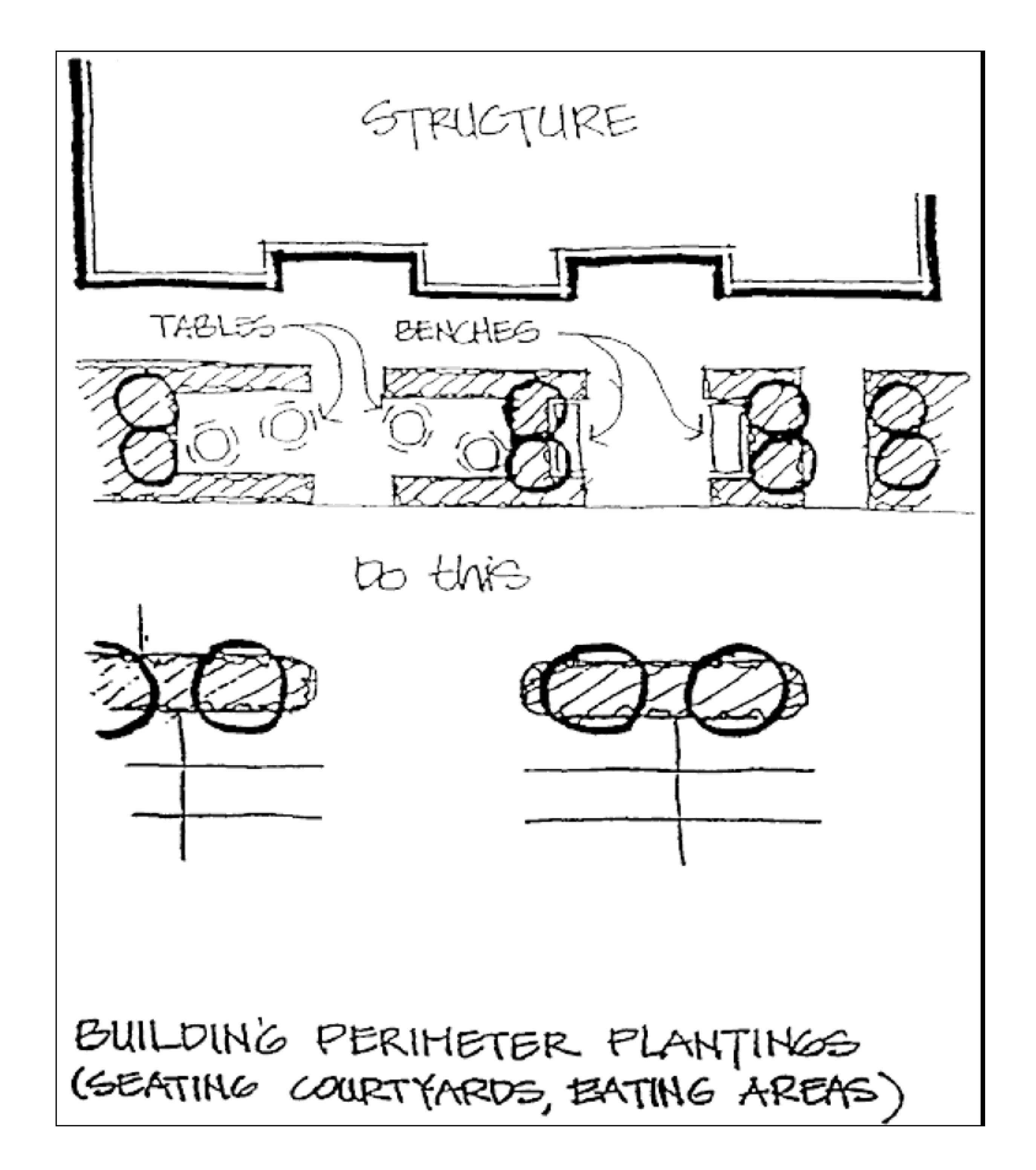
Outdoor public use and open space. Projects are encouraged that are designed to establish, define, and integrate outdoor public use areas into the development. This is especially important in the business district area. Public use areas must incorporate (but shall not be limited to) such uses and activities as seating, dining, special events, and entertainment. Well-defined pedestrian corridors shall be utilized to interconnect such areas with multiple developments and with required open space areas.
2.6
Fencing and Screening to mitigate off-site visual impacts. The off-site visual impacts associated with outdoor service functions or areas such as loading areas, trash collections, outdoor storage, or mechanical equipment shall be mitigated by the use of screening material. This material shall be consistent with the materials and design treatments of the primary facade of the primary building. In addition, landscaping shall also be incorporated into the overall screening concept. Chain link fencing shall not be utilized except in areas out of public view, and in conjunction with appropriate landscaping material to mitigate off-site impacts.
2.7
Signs. Please refer to division IV, chapter 3 of the land development regulations for requirements pertaining to signs.
3.
Building design guidelines.
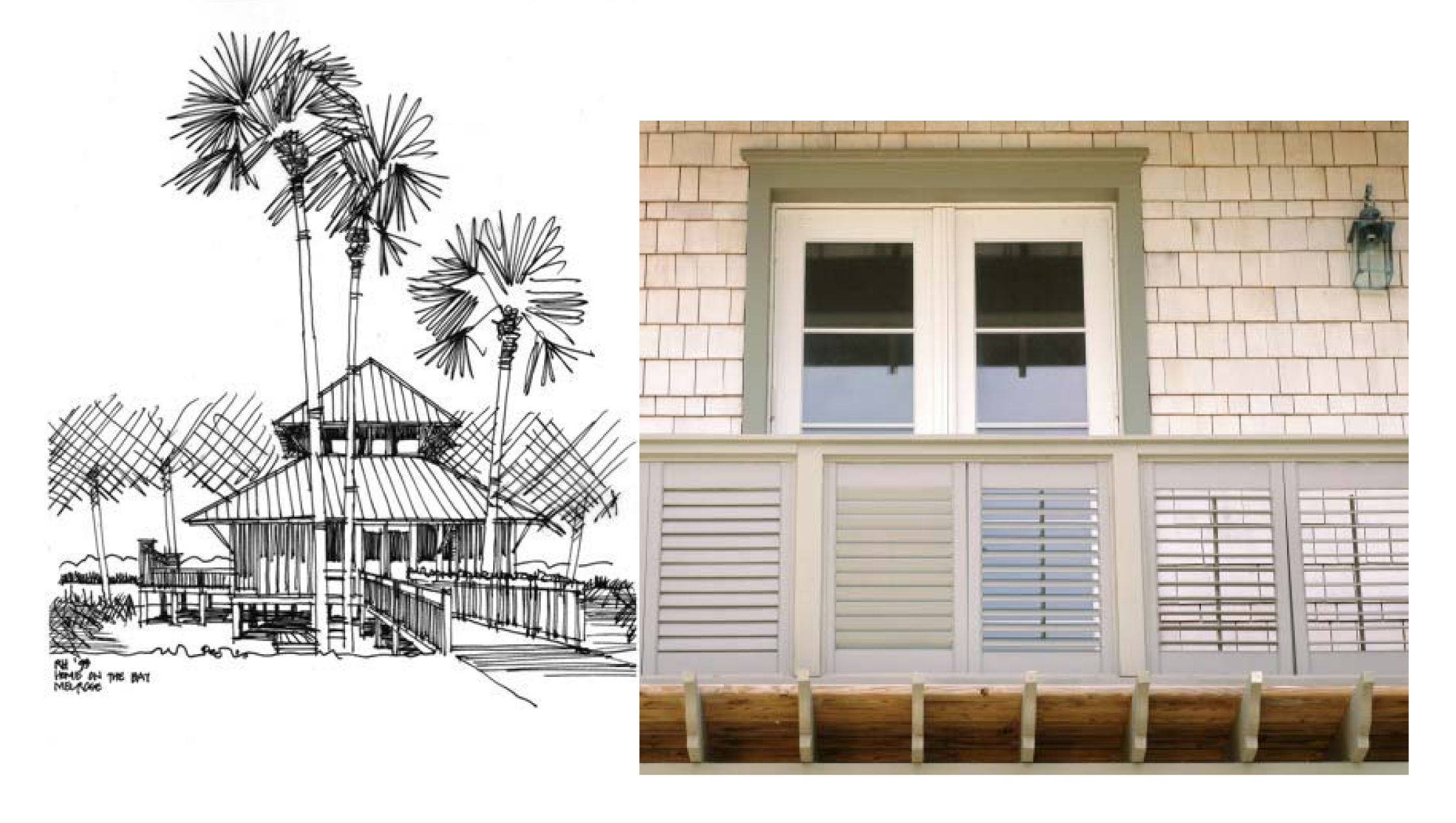
The plan establishes common or general building design guidelines that incorporate the design elements of architecture typical of the Florida Cracker and/or Key West style. This local, or vernacular style, is not limited to one particular design style. Furthermore, no particular style of architecture is necessarily prohibited. Design flexibility is encouraged with an overall goal of providing the CRA area with a unified "sense of place" on a pedestrian scale. The overall primary design elements that compose two of the state's indigenous architectural styles can be generally described or allocated to the following design components:
Generally stated, the goal is to relate the on-site design elements to the contextual setting. From a site planning prospective, these design elements include, but are not limited to, the following:
•
Architectural features and patterns that provide visual interest from the pedestrian's perspective through the integration and application of architectural detail and appropriate scale.
•
Building facades that are designed to reduce the mass/scale and uniform monolithic appearance of large, unadorned walls.
•
The incorporation of architectural details and elements and the use of scale to provide visual interest.
•
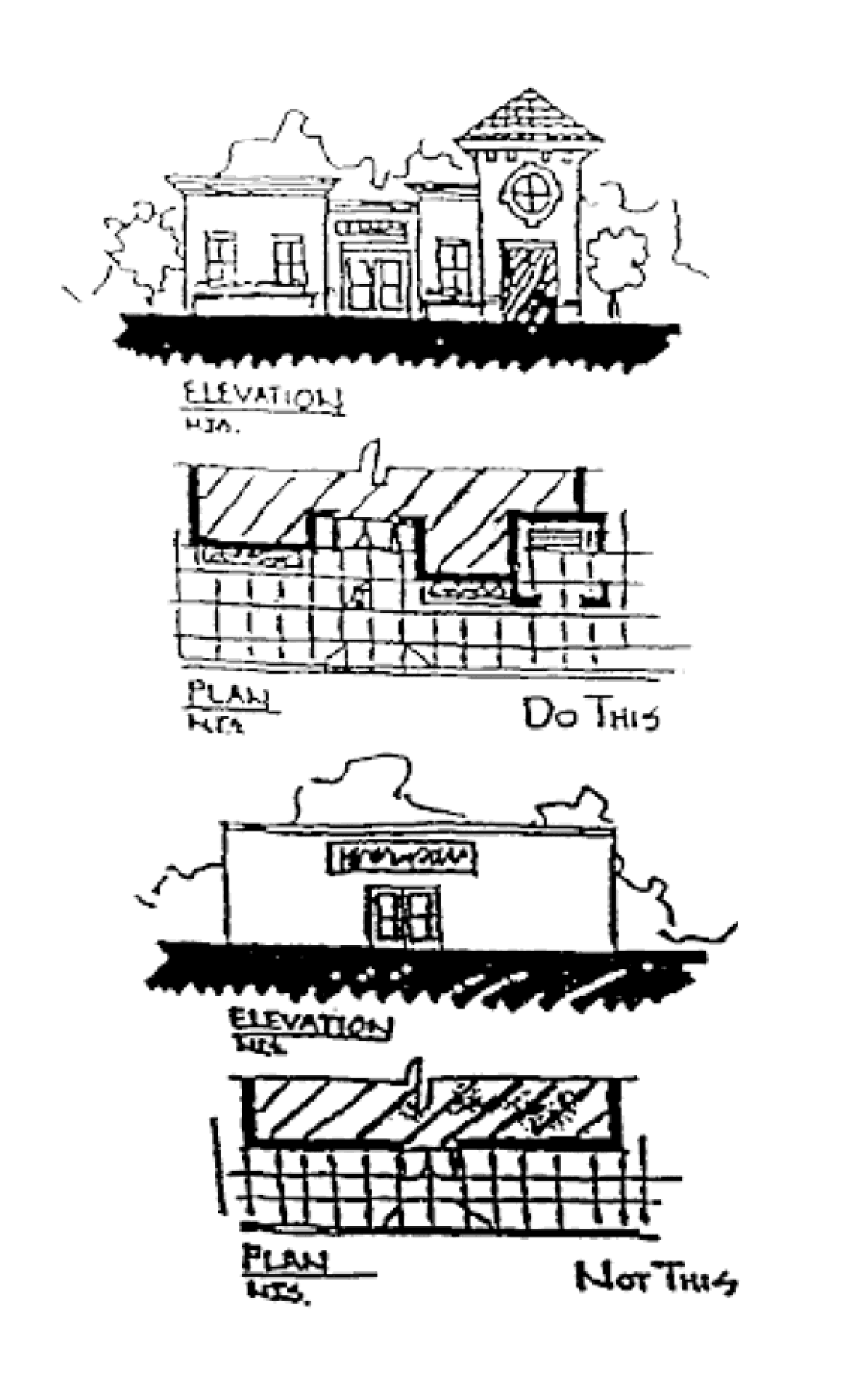
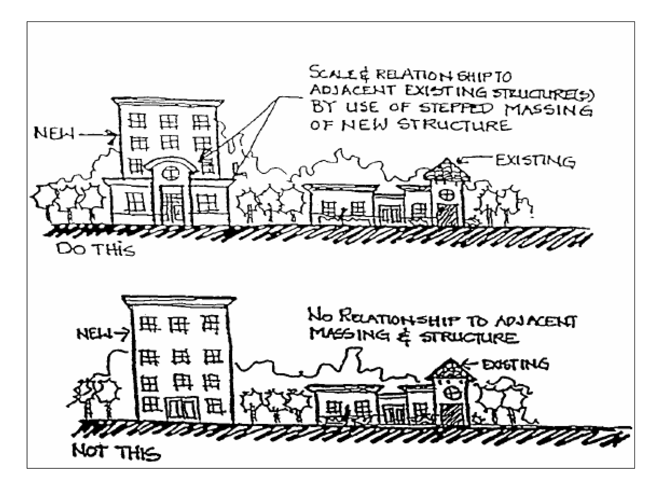
Variation in building mass, height, and width so the building appears divided or articulated into distinct massing elements and details perceived at the pedestrian scale.
•
The incorporation and integration of appropriate exterior building materials and colors consistent with the local vernacular style.
•
The use of roof forms that provide visual interest and reflect the primary elements of the local vernacular architecture.
3.1
Architectural features and patterns. Buildings shall incorporate architectural features and patterns that provide visual interest from the pedestrian perspective. This includes the incorporation of building facades that are not uniform in mass or scale and height. Large, unadorned or uniform monolithic facades and walls shall be avoided. Pedestrian scale facade treatments such as (but not limited to) canopies, overhangs, arcades, gabled entryways, and porticos are encouraged.
3.2
Building facades. Building facades shall be articulated and designed using consistent and integrated architectural style, detail, and trim features. Appropriate building facade materials and colors are addressed below. Buildings located adjacent to arterial or collector roadways shall incorporate windows along 50 percent or more of the horizontal length of the primary customer entrance facade. This must be achieved through the appropriate application of faux windows or similar architectural detail.
3.3
Incorporation of architectural details and elements, and the use of scale. The overall architectural style of a building's facade shall incorporate design elements and details that promote a pedestrian scale. This must be achieved by incorporating repeating facade treatments. These treatments shall include multiple architectural details and trim components consisting of changes in color, texture, material, and the expression of architectural or structural bays via a change in plane using a reveal, offset, or projecting rib. Uninterrupted or blank wall facades shall be avoided. Multiple tenant buildings with separate articulated entrances are encouraged, and pedestrian scale windows, and other design elements such as, but not limited to, display windows, overhangs, awnings, canopies or porticos, gable roofed entryways, and arcades.
3.4
Variation in building mass, height and width to achieve pedestrian scale. Buildings shall have architectural features and patterns providing visual interest for the pedestrian, and articulating a streetscape with a sense of community. Building facades shall be designed to reduce the mass, scale, and uniform monolithic appearance of large, unadorned walls. This must be accomplished by varying the building's mass in height and width so it appears divided into distinct massing elements with details perceived at the pedestrian scale. Exterior facades shall also be designed with projections and recesses of varying depths. Variations in roof lines shall be used to reduce the massing of buildings. Roof edges shall have a vertical change from the dominant condition. Multiple roof slope planes which incorporate gables are encouraged.
3.5
Building materials and colors consistent with the cracker or Key West style. The exterior building materials and colors shall reflect the elements of the local vernacular style and shall be indigenous to the area. Building facades shall be composed of natural materials such as brick, stone, or wood siding. High quality, man-made materials such as stucco and tinted or textured concrete masonry units are acceptable. Exterior building materials not permitted for use are plastic or vinyl sidings, corrugated or reflective metal panels, sheathing, tile, smooth or rib-faced concrete blocks or panels, stone in an ashlar or rubble look, or other simulated natural materials. Appropriate roofing materials include wood shakes, metal standing seam, architectural grade asphalt shingles, and tile. Exterior building and roofing material colors shall be natural, subdued earth tones or soft pastels. Primary colors, black, fluorescent colors, metallic or reflective colors shall be avoided, or used only to emphasize or accent an architectural design element of the building facade.
3.6
Roof forms. The local vernacular style incorporates the use of articulated and sloping roof forms which provide visual interest. Gabled roofs are a primary expression of this style. The use of dormers which provide an additional element of architectural detail and interest to uninterrupted roof planes is also a common architectural component of the local vernacular style. Flat roofs shall only be utilized in such areas as entrance canopies, storage and mechanical equipment areas, arcades, and walkway or breezeway connections that provide pedestrian protection from the weather.
4.
Illustrative guidelines.
Figures 1 through 26 are provided as illustrative examples of the site planning and building design principles and guidelines previously outlined. The illustrations demonstrate an appropriate application of a specific concept, and as such are not intended to limit different approaches that may also articulate the outlined design principles. The drawings provided are illustrative and reflect generalized concepts and shall not be construed literally.
The site planning process for each parcel shall include consideration of the property location, orientation, and configuration of buildings and attendant structures on the site, regarding site boundary lines, adjacent streets, buildings, and open spaces. Standardized building designs with overt "product branding", typical of franchise establishments shall be discouraged. Site planning and building design shall consider pedestrian circulation, both on-site and between adjacent sites.
4.1.
Figure 1 - Site analysis.
A site analysis shall be considered in site planning of proposed developments. Site analysis will assist in the identification and evaluation of natural feature, site characteristics and their interrelation to surrounding areas. This analysis will be used in the site design process.

Illustration Credit: Leon County Planning Department
4.2.
Figure 2 - Creation of outdoor spaces and public use areas.
4.3.
Figure 3 - Street/sidewalk continuity.
New projects and redevelopment projects shall interconnect with existing walks.
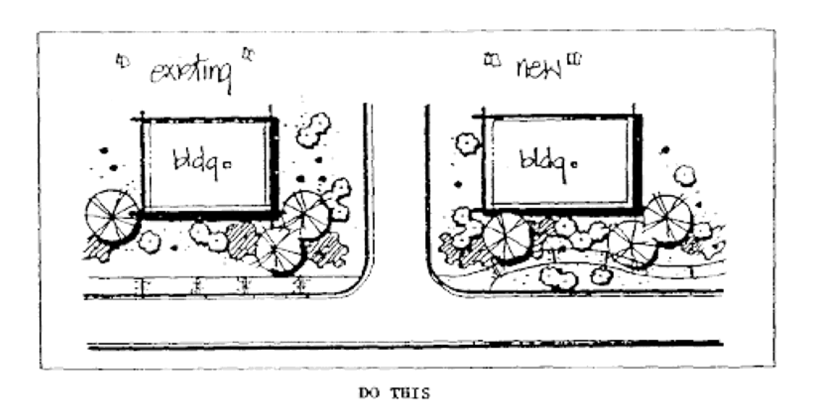
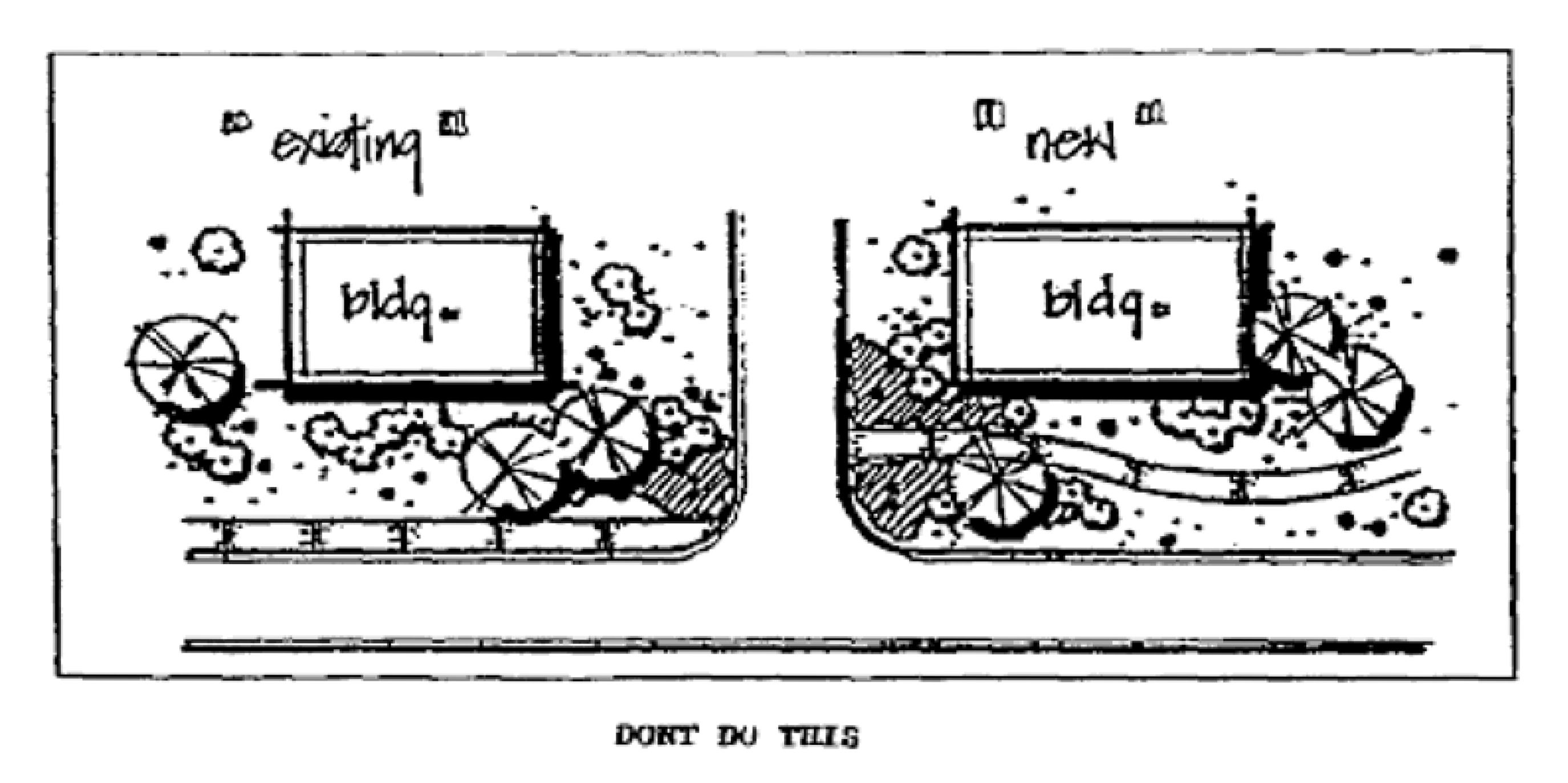
Illustration credit: City of Sedona, Arizona, Land Development Code
4.4.
Figure 4 - Simple circulation patterns.
Pedestrian circulation patterns shall be simple and easily comprehended by the user, and generally shall follow landscaped islands and perimeters leading directly to building.
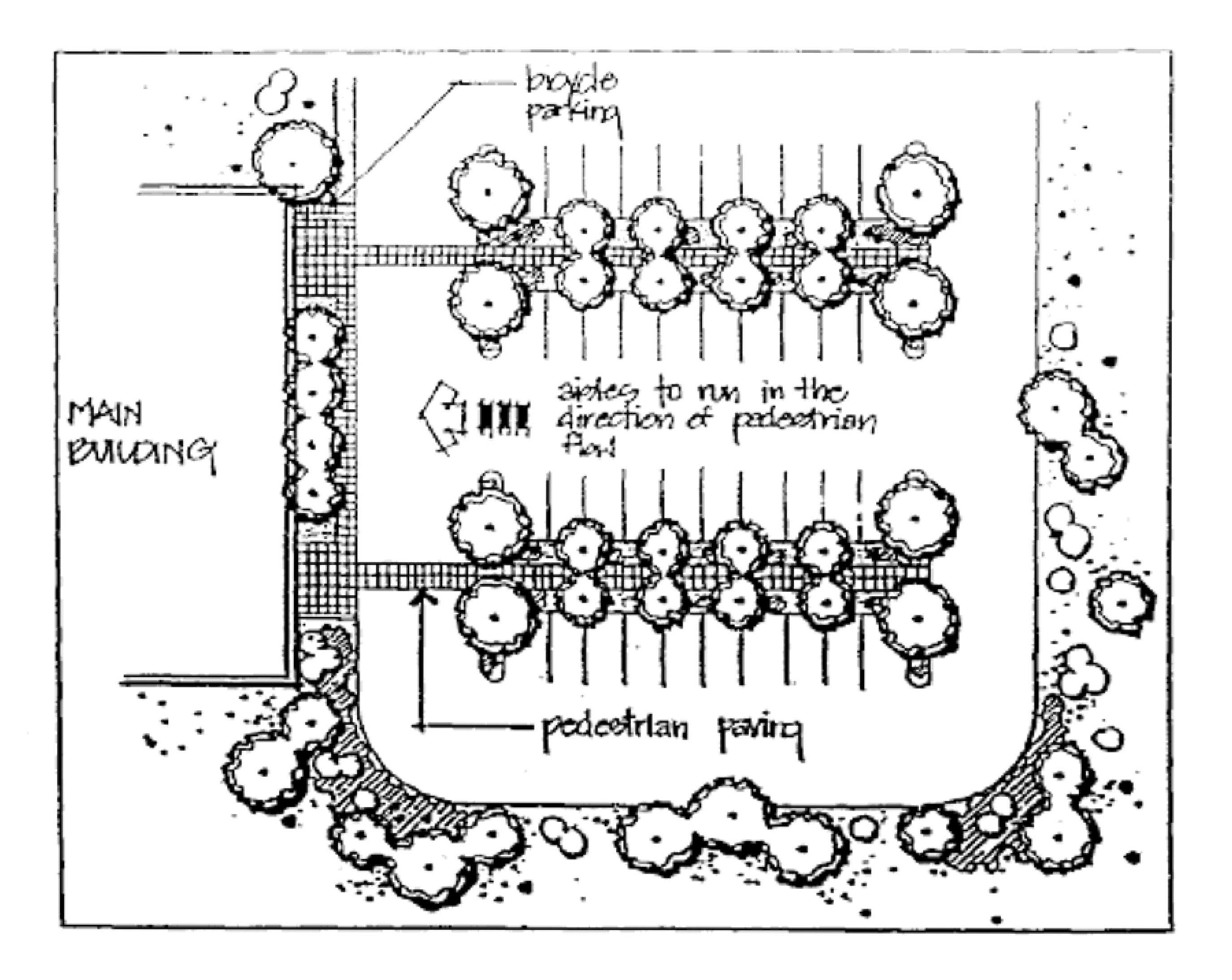
Illustration credit: City of Sedona, Arizona, Land Development Code
4.5.
Figure 5 - Pedestrian crossings.
Material and/or color changes shall occur where pedestrian pathways cross all vehicular use areas.
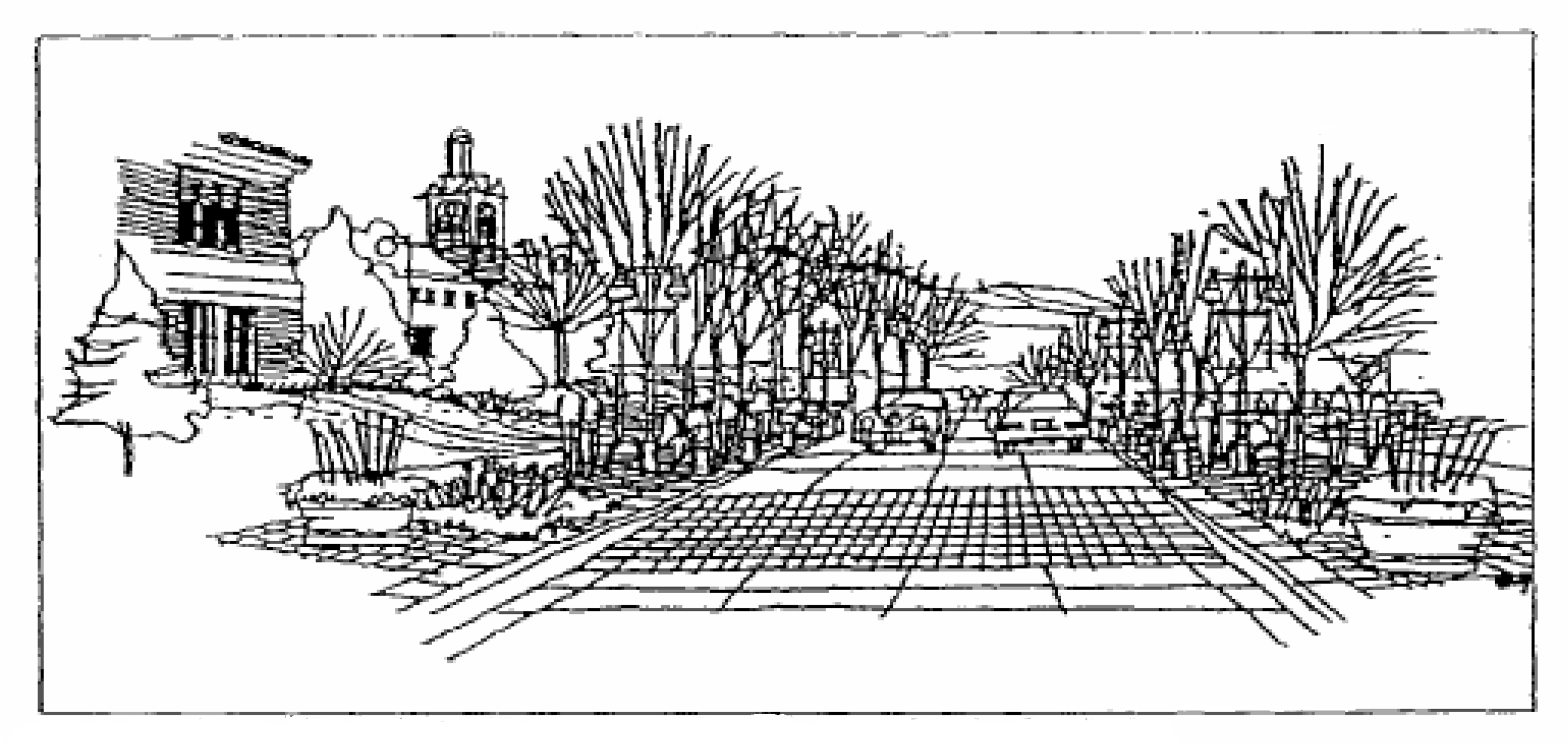
Illustration credit: City of Fort Collins, Colorado, Site Planning and Design Standards
4.6.
Figure 6 - Walks and patios.
Walks and patios shall be included as part of an overall comprehensive landscape plan. The use of plant materials, planters, and multiple paving materials within the overall project design is encouraged. Where underground utilities need to be accessed under walkways or patio areas, then modular units which are easily removable and replaced shall be used to reduce waste.
Free-form, meandering sidewalks and paths are preferred, rather than rigid, straight-line
alignments.
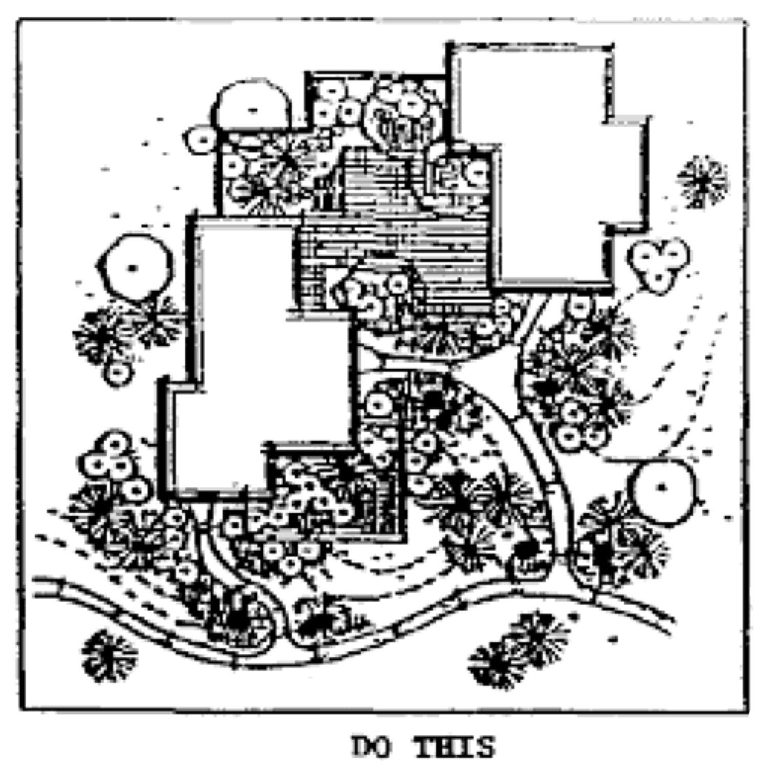

Illustration credit: City of Sedona, Arizona, Land Development Code
4.7.
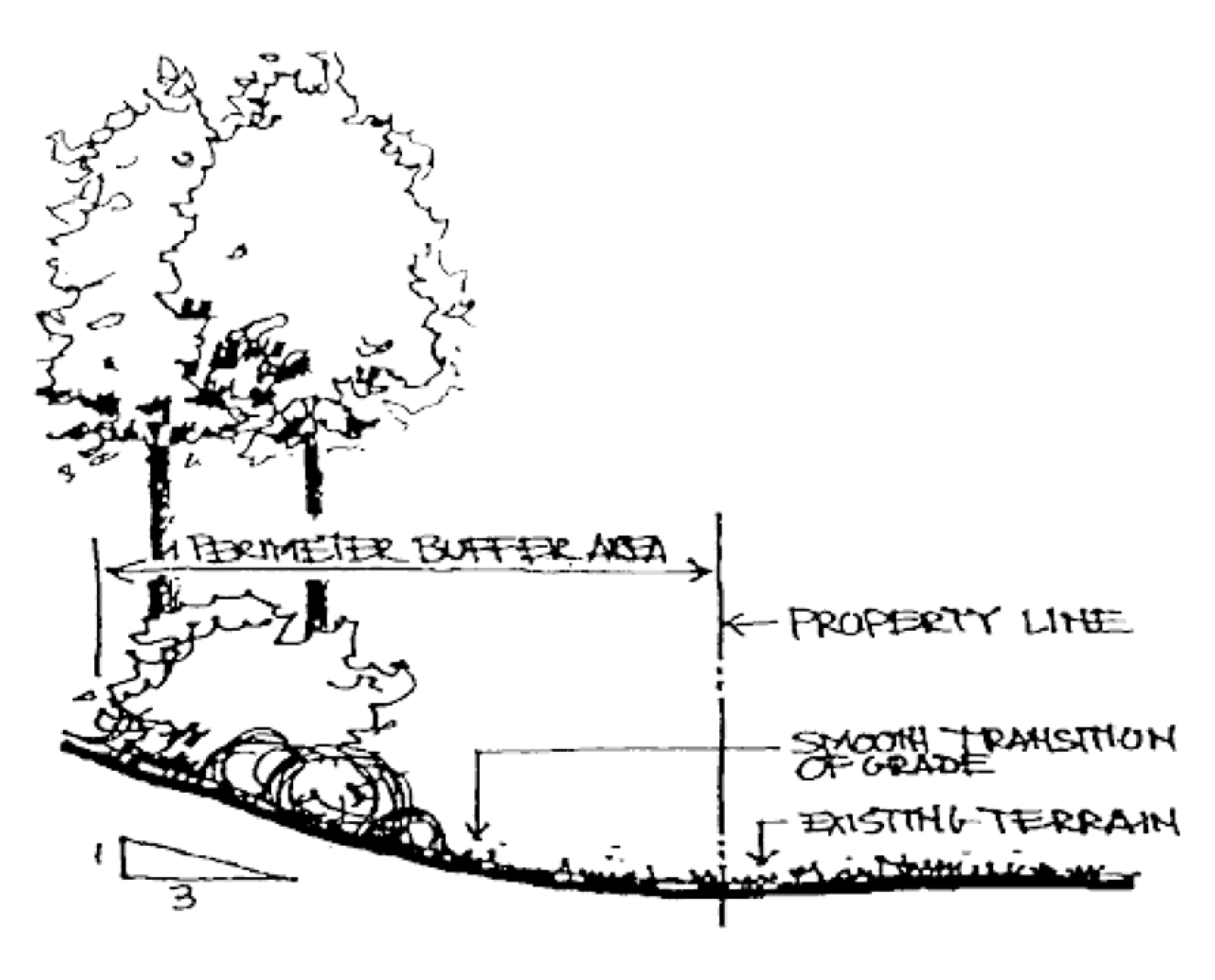
Figure 7 - Landscape buffers.
Landscape buffers will maintain a sense of the natural surroundings by the use of indigenous plant material and the incorporation of existing vegetation. Landscape improvements shall be structured to create filtered views and vistas both within and out of the site.
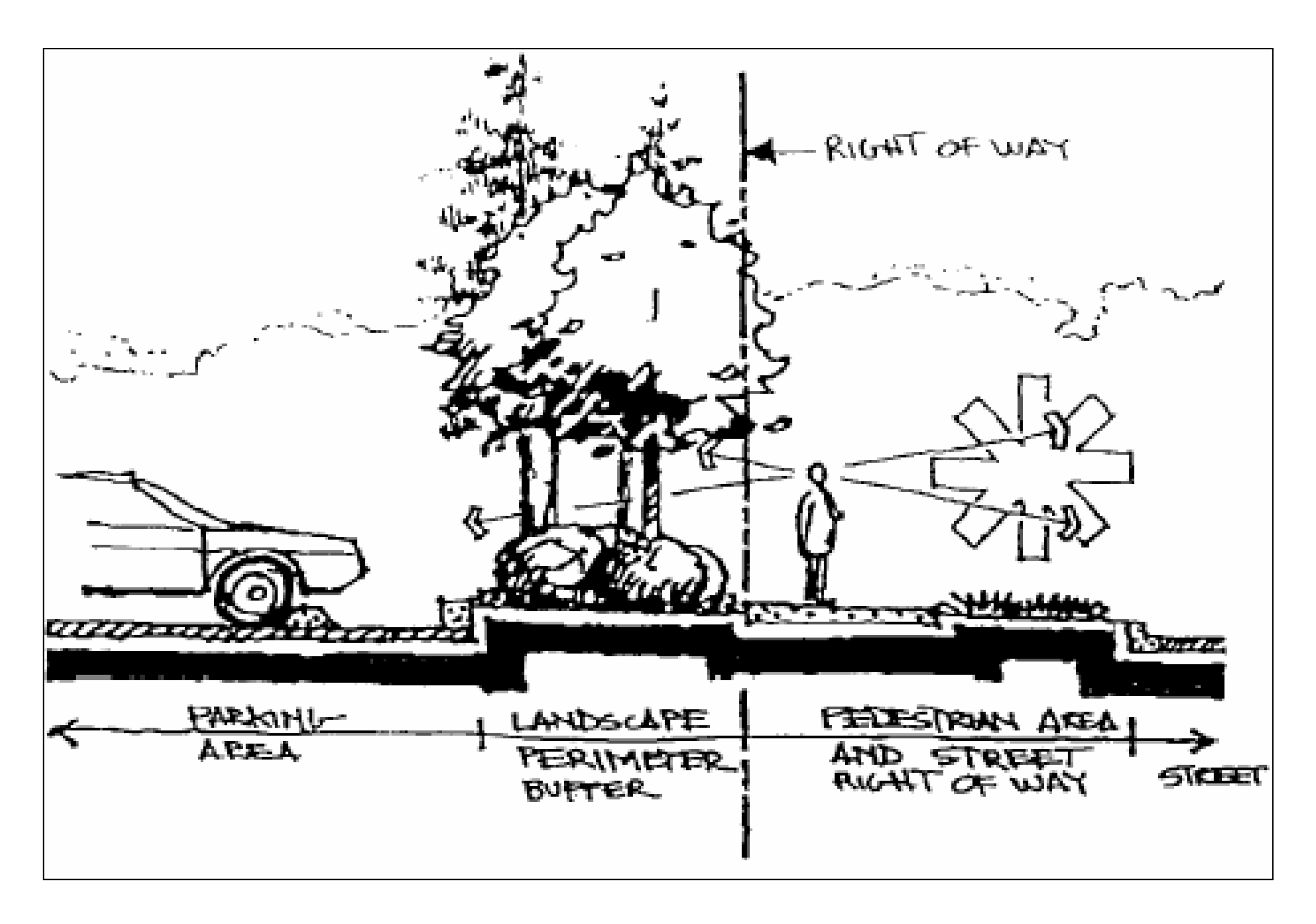
Illustration Credit: Leon County Planning Department
4.8.
Figure 8 - Walkways.
Walks shall be included as part of an overall comprehensive landscape plan. Free-form, meandering sidewalks and paths are preferred to preserve natural vegetation or to create landscape views. Walkways consisting of geometric alignments shall be utilized if determined more appropriate for the design application.
Encouraged materials include colored concrete, paver blocks and other bituminous materials.

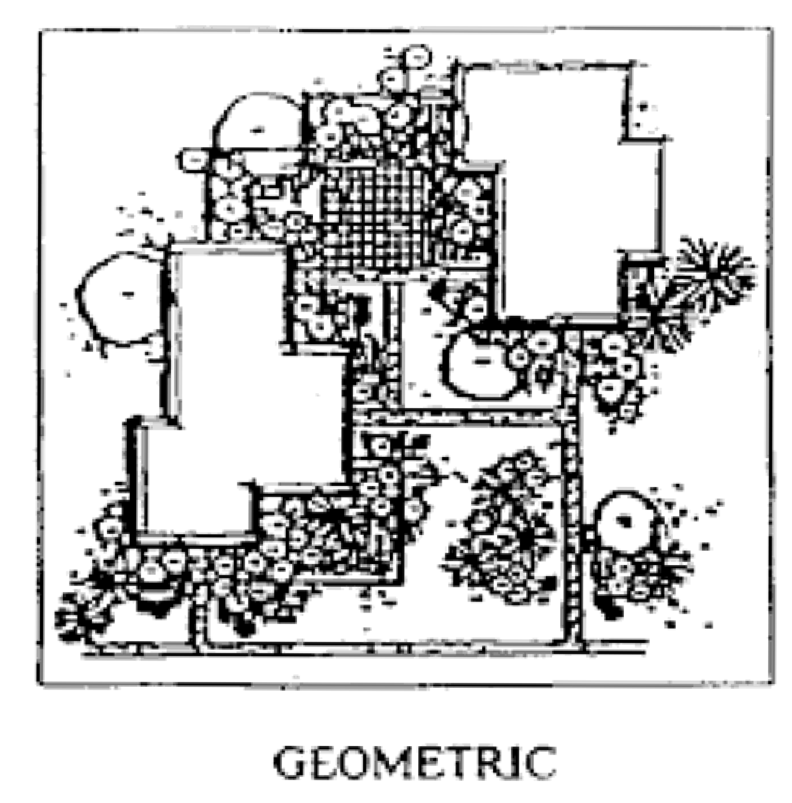
Illustration Credit: Leon County Planning Department
4.9.
Figure 9 - Earthwork disturbances.
Building placement on slopes shall not only develop stepped massing, but shall also create plan view offsets to save vegetation and landforms.
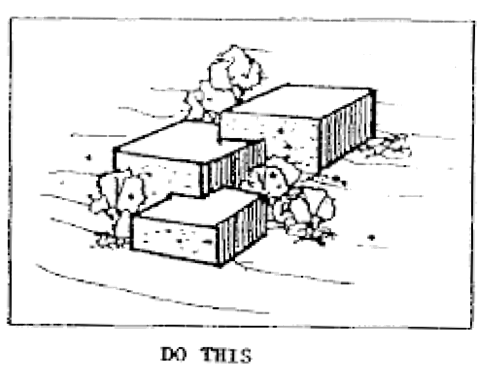

Illustration credit: City of Sedona, Arizona, Land Development Code
4.10.
Figure 10 - Visually connected open spaces.
Open spaces and landscape areas shall provide visual connection between similar spaces
on adjacent sites by creating unobstructed views and applying the use of complementary
elements (i.e. walkways, vegetation, lighting) within the open space.
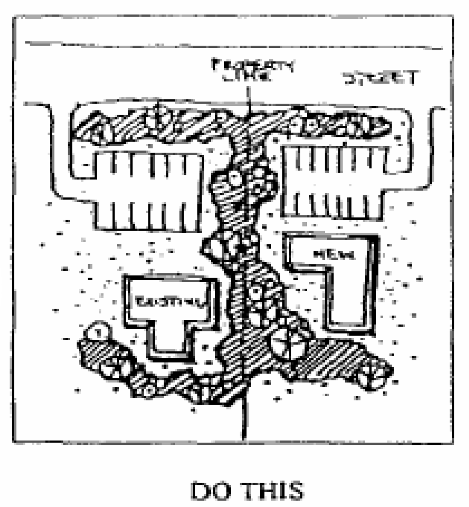
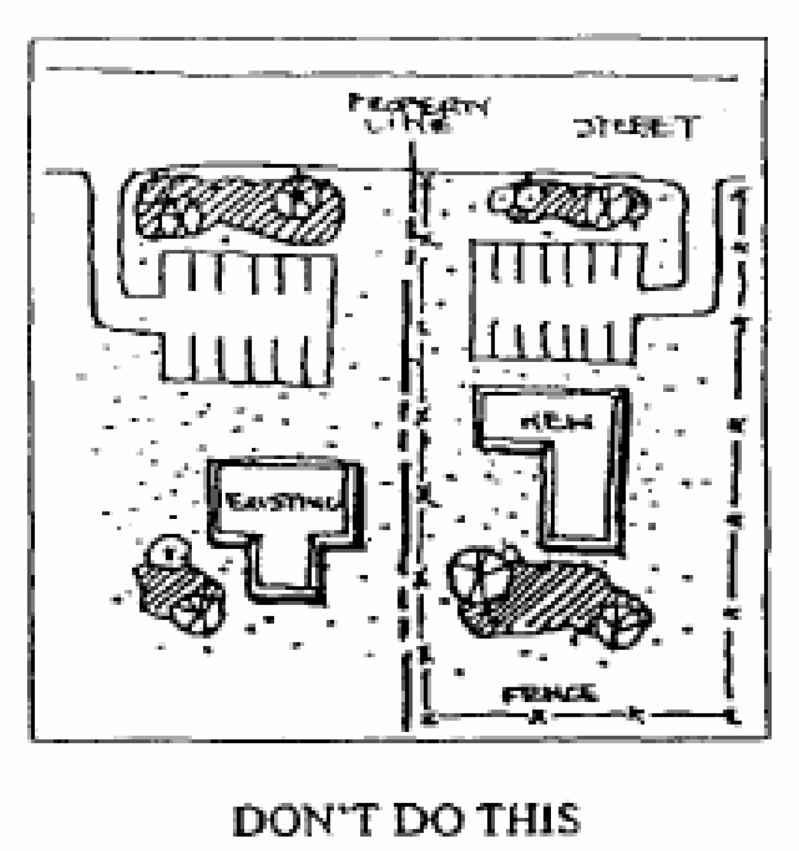
Illustration Credit: Leon County Planning Department
4.11.
Figure 11 - Articulate fences and walls.
Walls and fences greater than 40 feet in unbroken length shall be designed to increase shadow patterns, provide interesting visual effects and reduce apparent mass. Walls and fences on slopes shall follow the terrain.
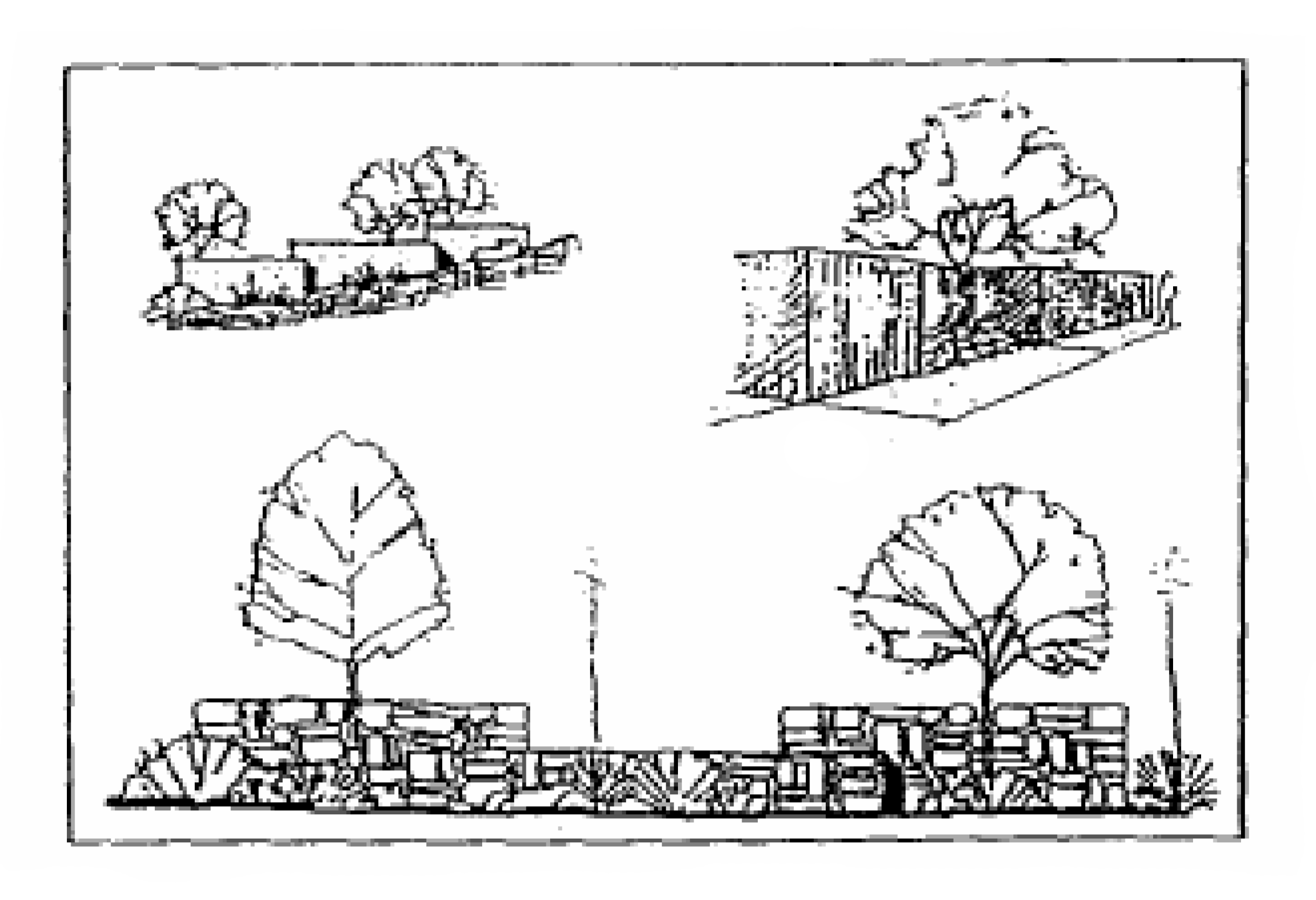
Illustration Credit: Leon County Planning Department
Where a new wall or fence creates a continuous surface greater than 20 feet in length, it shall also be softened visually with tree, shrub, and/or vine plantings.
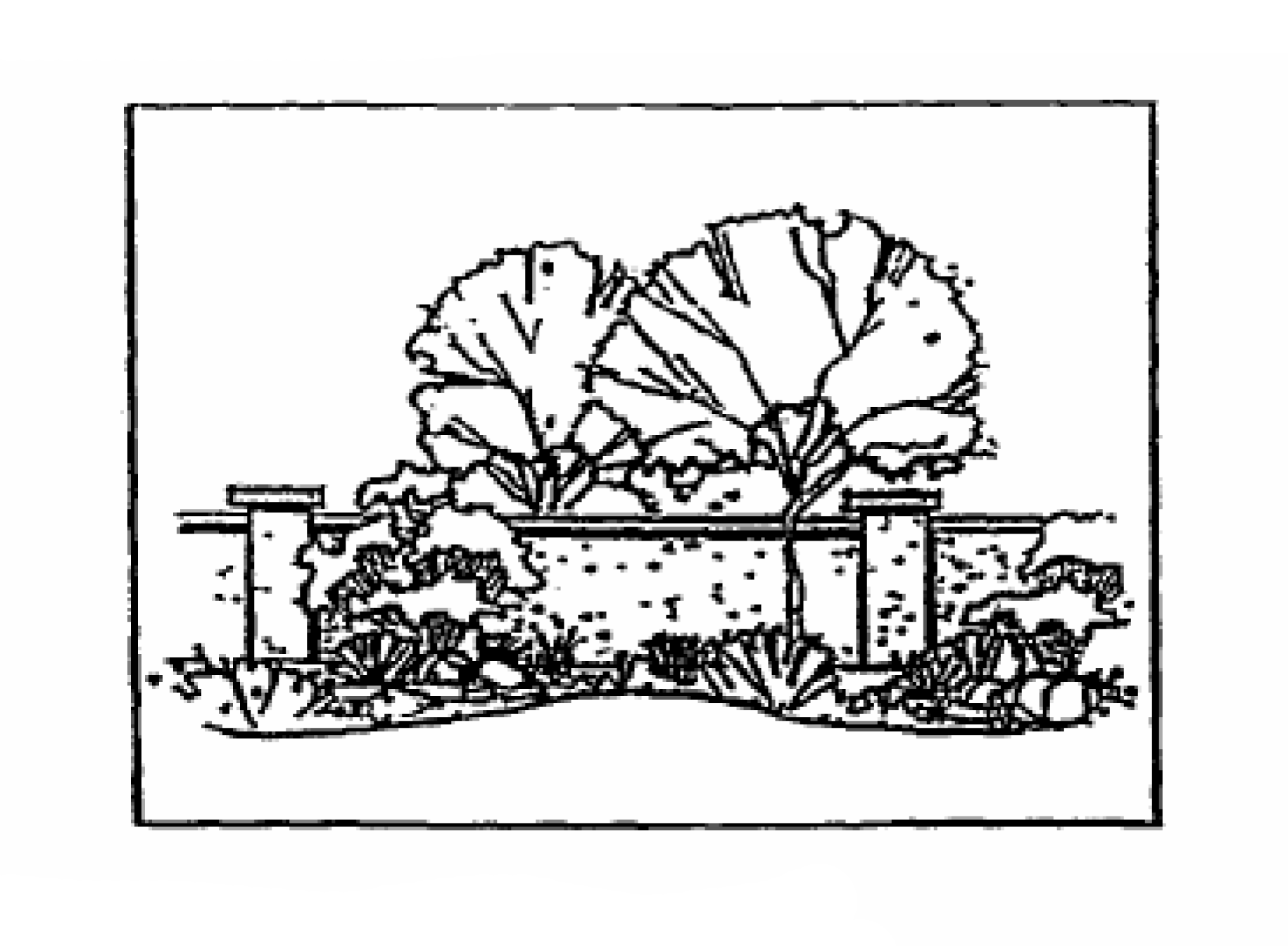
Illustration credit: City of Sedona, Arizona, Land Development Code
4.12.
Figure 12 - Topographic transitions.
Transitions at property edges shall seem natural for the surrounding terrain. Where the existing terrain is generally level, avoid slopes greater than 1:3 at property lines. Preservation of natural features may require alternative slope conditions.
4.13.
Figure 13 - Cut and fill slopes.
Cut and fill slopes shall be rounded where they meet natural grade so that they blend with the natural slopes.
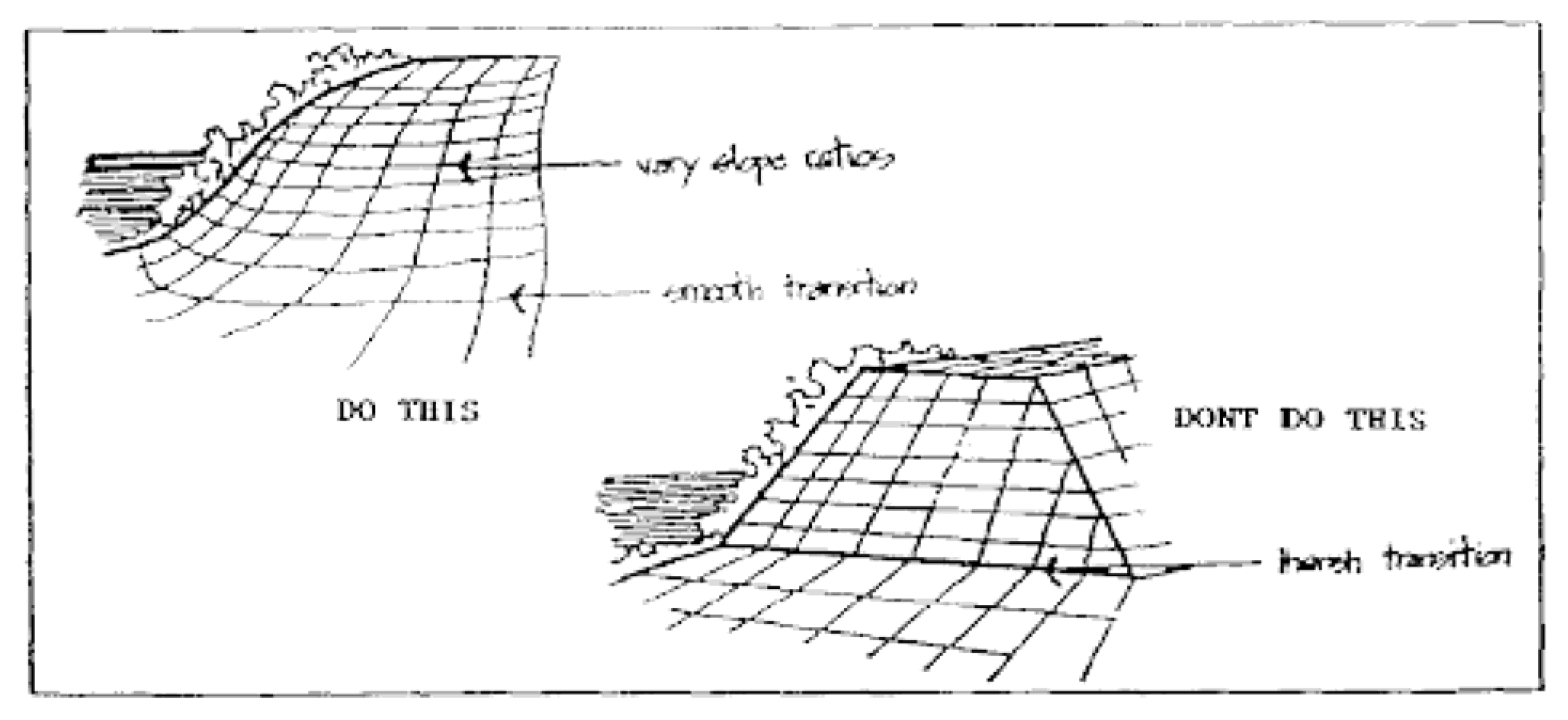
Illustration credit: City of Sedona, Arizona, Land Development Code
4.14.
Figure 14 - Drainage channels.
The use of concrete channelization for drainages requiring mechanical stabilization
is discouraged. A preferred method is armoring with drylaid native or riverwashed
rock of a variety of shapes and sizes to provide a more natural appearance, allowing
for some vegetation and encouraging the groundwater recharge process. Uniform coverage
by such armoring is discouraged, but emphasis shall be placed on naturally shaped
coverages where the drainages are most prone to erosion, such as on the outside of
curves. Riparian tree planting on such portions of drainage edges may be combined
with such emphasized armoring.

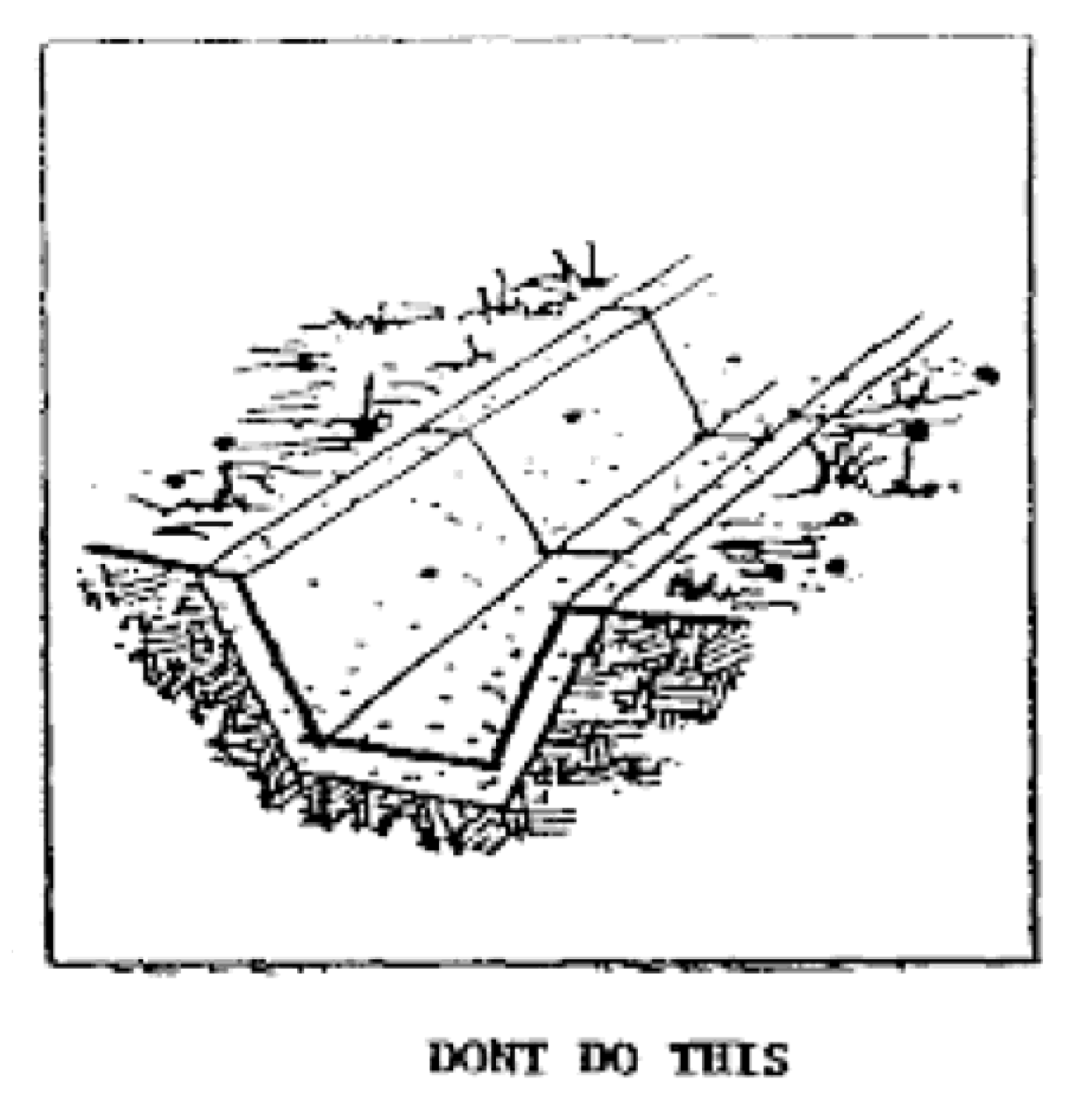
Illustration credit: City of Sedona, Arizona, Land Development Code
4.15.
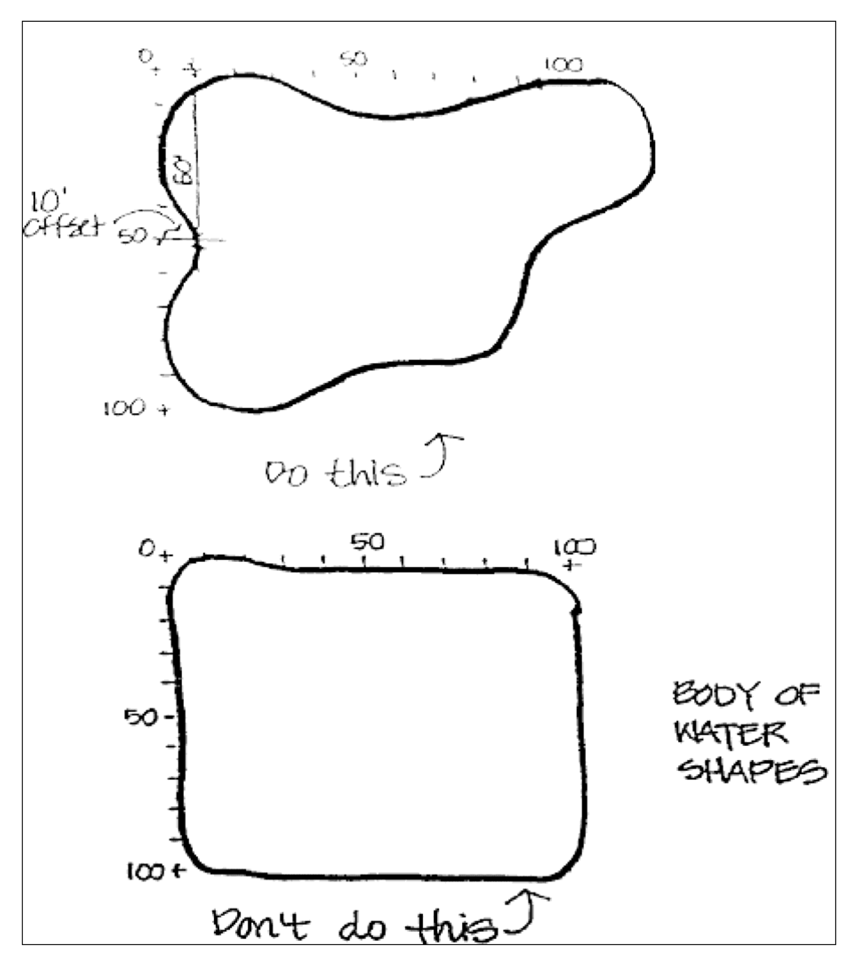
Figure 15 - Naturally shaped storm water management facilities.
4.16.
Figure 16 - Service areas.
Service areas shall be located to the rear, side, or to an internal location where visibility from public streets and windows of neighboring buildings will be minimized.
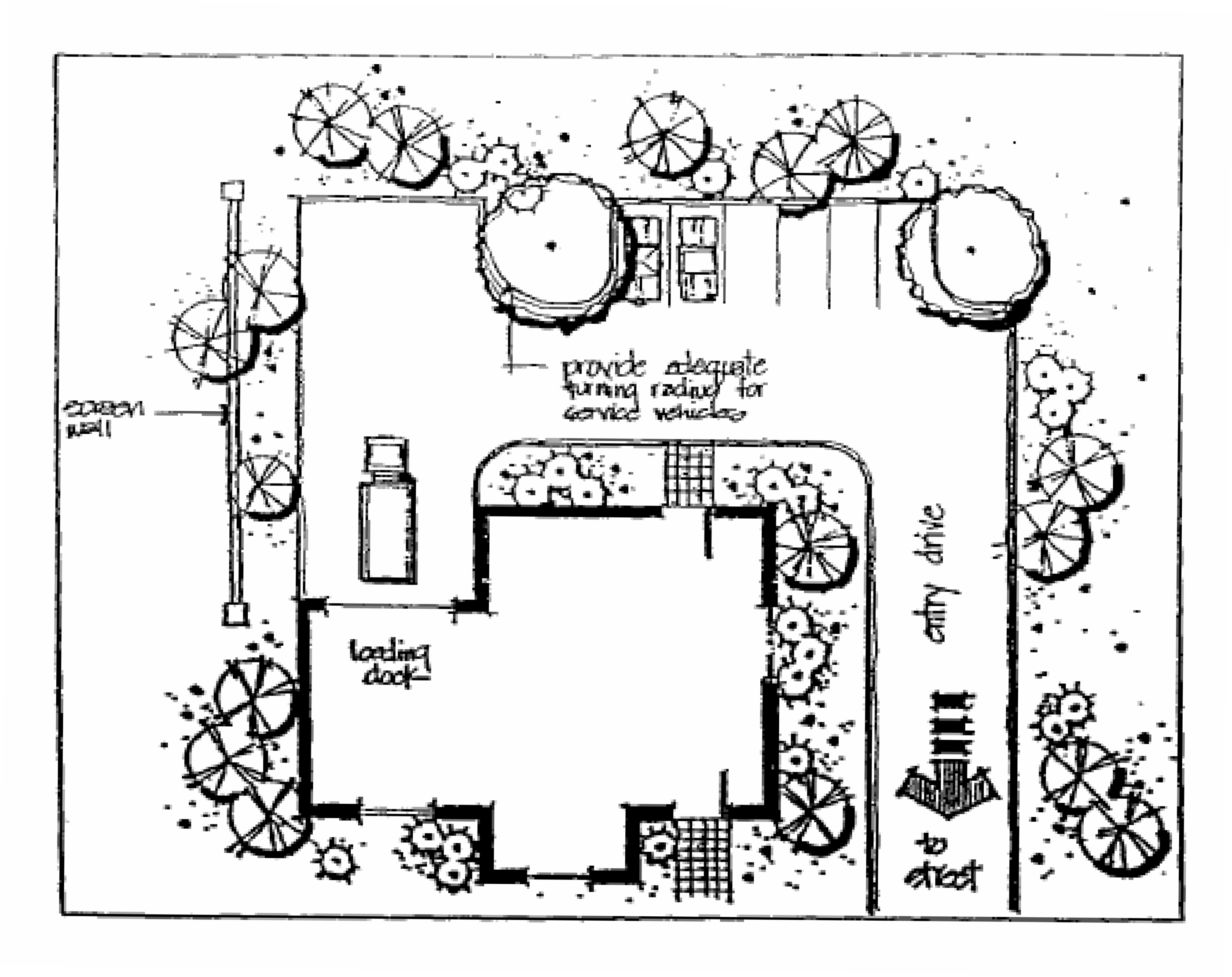
Illustration credit: City of Sedona, Arizona, Land Development Code
4.17.
Figure 17 - Mechanical equipment.
Mechanical equipment such as air conditioners, dumpsters, electrical meters, tanks, etc., shall be screened by appropriate walls and fences and softened visually with vine and shrub plantings. Small surface-mounted equipment such as valves, gas, electric and water meters, must be screened efficiently by appropriate shrubs and landscape design.
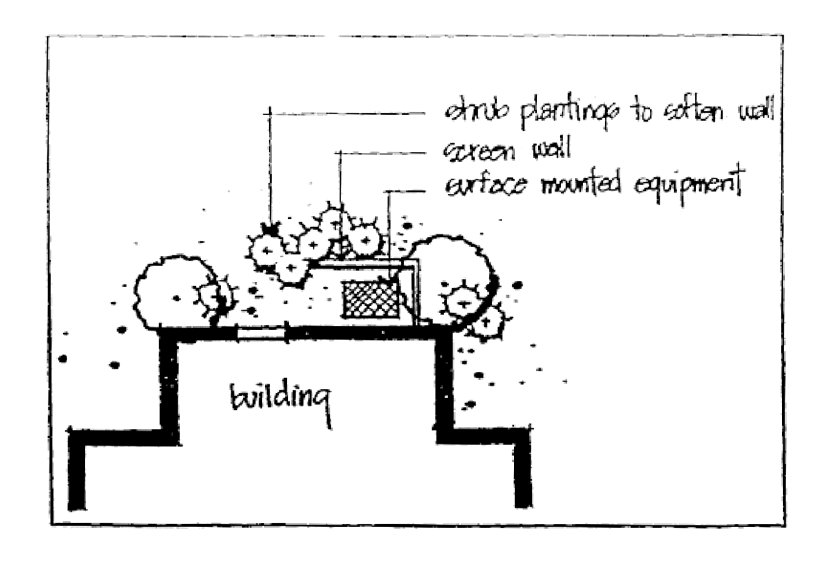
Illustration credit: City of Sedona, Arizona, Land Development Code
4.18.
Figure 18 - Mechanical equipment & accessory uses.
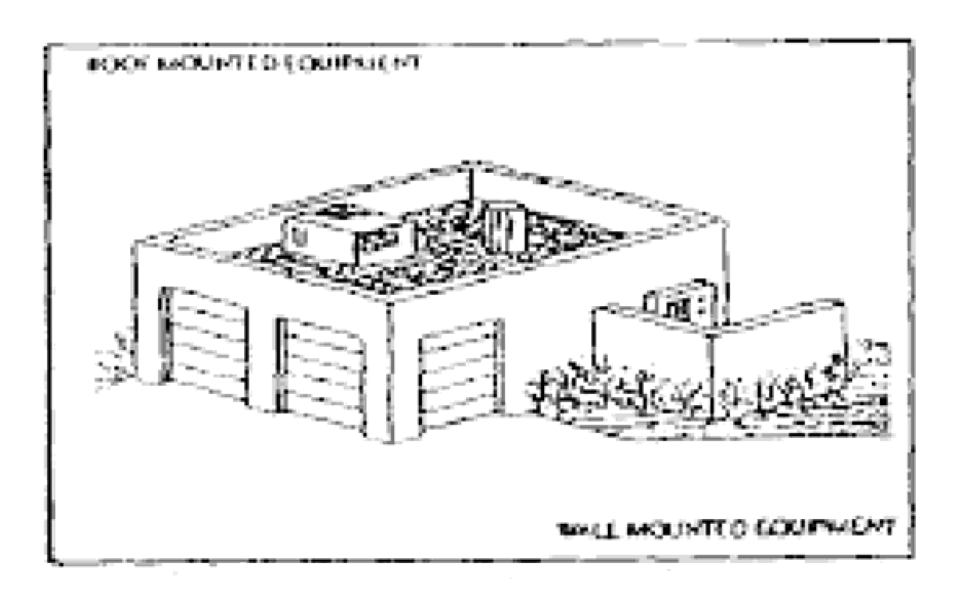
Illustration Credit: City of Santa Fe, New Mexico, Architectural Design Review Handbook
In the initial design stage of a development project, consideration shall be given
to incorporating mechanical and electrical equipment into the architectural form and
layout of the building to reduce the need for screening.
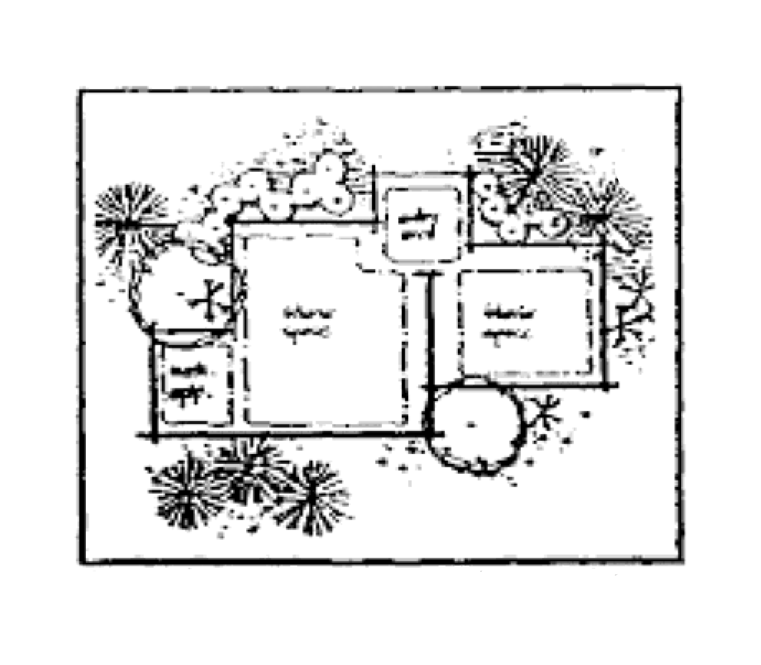
Illustration credit: City of Sedona, Arizona, Land Development Code
Uses and equipment to be screened:
The following equipment and uses shall be screened from public right-of-ways, access ways, and adjacent properties:
•
Trash and refuse collection areas
•
Mechanical equipment such as air conditioners, pumps, and motors
•
Propane tanks and other storage tanks
•
Electrical equipment, including switching equipment and transformers
•
Valves, vents, and utility meters
•
Satellite dishes
•
Rooftop skylights to prevent unwanted light effects at night
•
Solar collectors
•
Grouped mailboxes
•
Grouped newsstands
4.19.
Figure 19 - Facades and exterior walls.
Facades shall be articulated to reduce the massive scale and the uniform, impersonal appearances of large retail buildings and provide visual interest that will be consistent with the community's identity, character and scale. The intent is to encourage a more human scale that area residents will be able to identify with their community. Standards:
a)
Facades greater than 100 feet in length, measured horizontally, shall incorporate wall plane projections or recesses having a depth of at least three percent of the length of the facade and extending at least 20 percent of the length of the facade. No uninterrupted length of any facade is to exceed 100 horizontal feet.
b)
Ground floor facades that face public streets shall have arcades, display windows, entry areas, awnings, or other such features along no less than 60 percent of their horizontal length.
c)
This provision shall not apply to mini-warehouse developments where buffered from public roadways, access ways, and adjacent land uses.
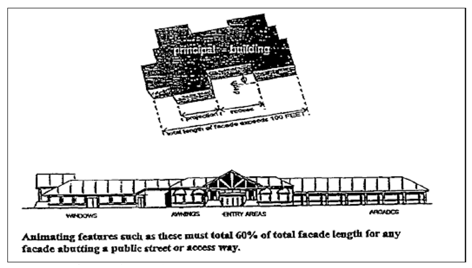
Illustration Credit: Leon County Planning Department
4.20.
Figure 20 - Building surfaces.
Large or long continuous wall surfaces shall be avoided. As a general principle, large building surfaces shall be relieved with a change or wall place that provides strong shadow and visual interest.
Every building shall reduce its perceived height and bulk by dividing the building
mass into smaller scale components.
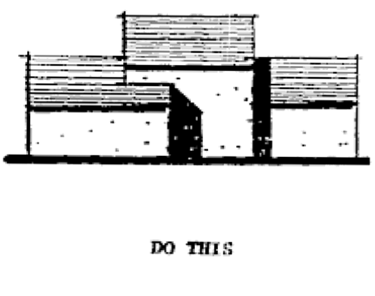
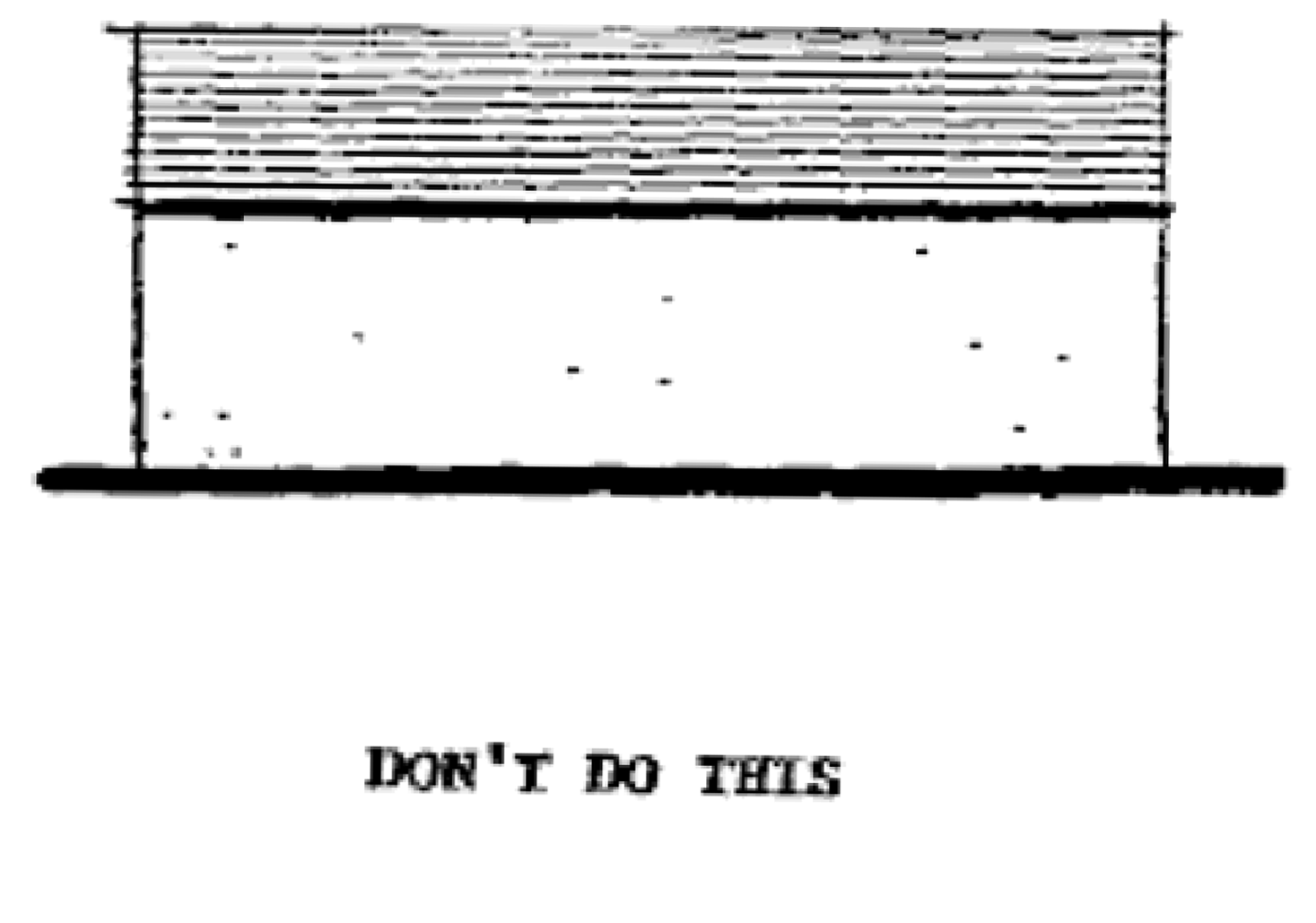
Illustration credit: City of Sedona, Arizona, Land Development Code
4.21.
Figure 21 - Building facades.
Architectural features and patterns shall be used to provide visual interest. Variations in building mass, height, and width shall be used to articulate a streetscape and to achieve pedestrian scale.
4.22.
Figure 22 - Creation of visually interesting street scape at a pedestrian scale.
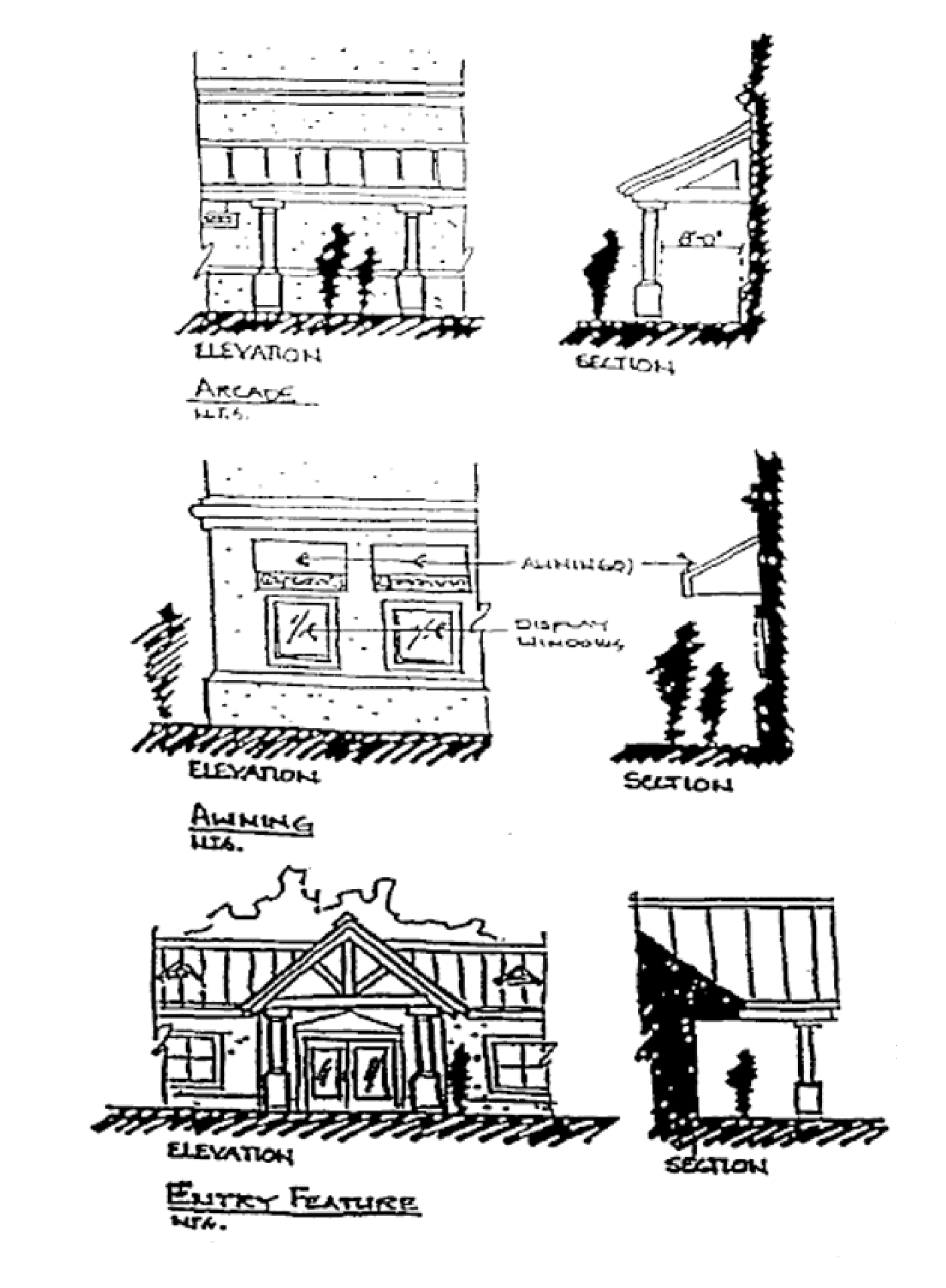
Illustration credit: Collier County, Florida, Land Development Code

4.23.
Figure 23 - Articulation of a consistent and integrated architectural style.
4.24.
Figure 24 - Building facade treatment.
Repeating facade treatments including a change in plane with the use of reveal, offset, or projecting rib must be used to provide architectural expression at a pedestrian scale.
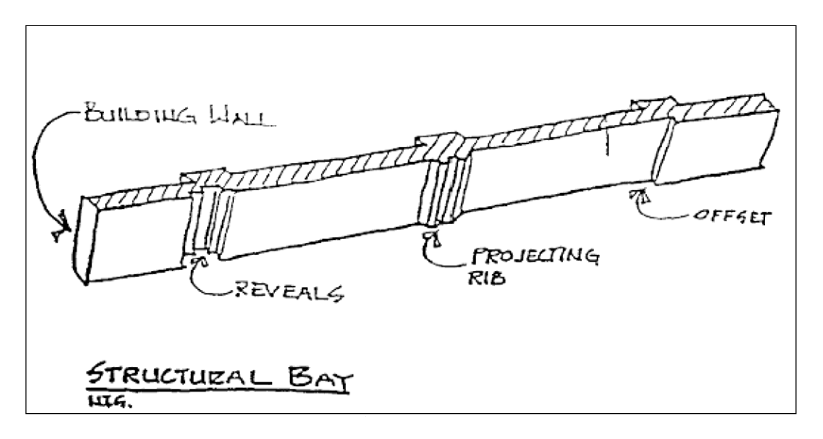
Illustration credit: Collier County, Florida, Land Development Code
4.25.
Figure 25 - Variation in roof lines.
Building massing must be reduced thereby achieving visual interest and pedestrian
scale by incorporating variation in roof lines.
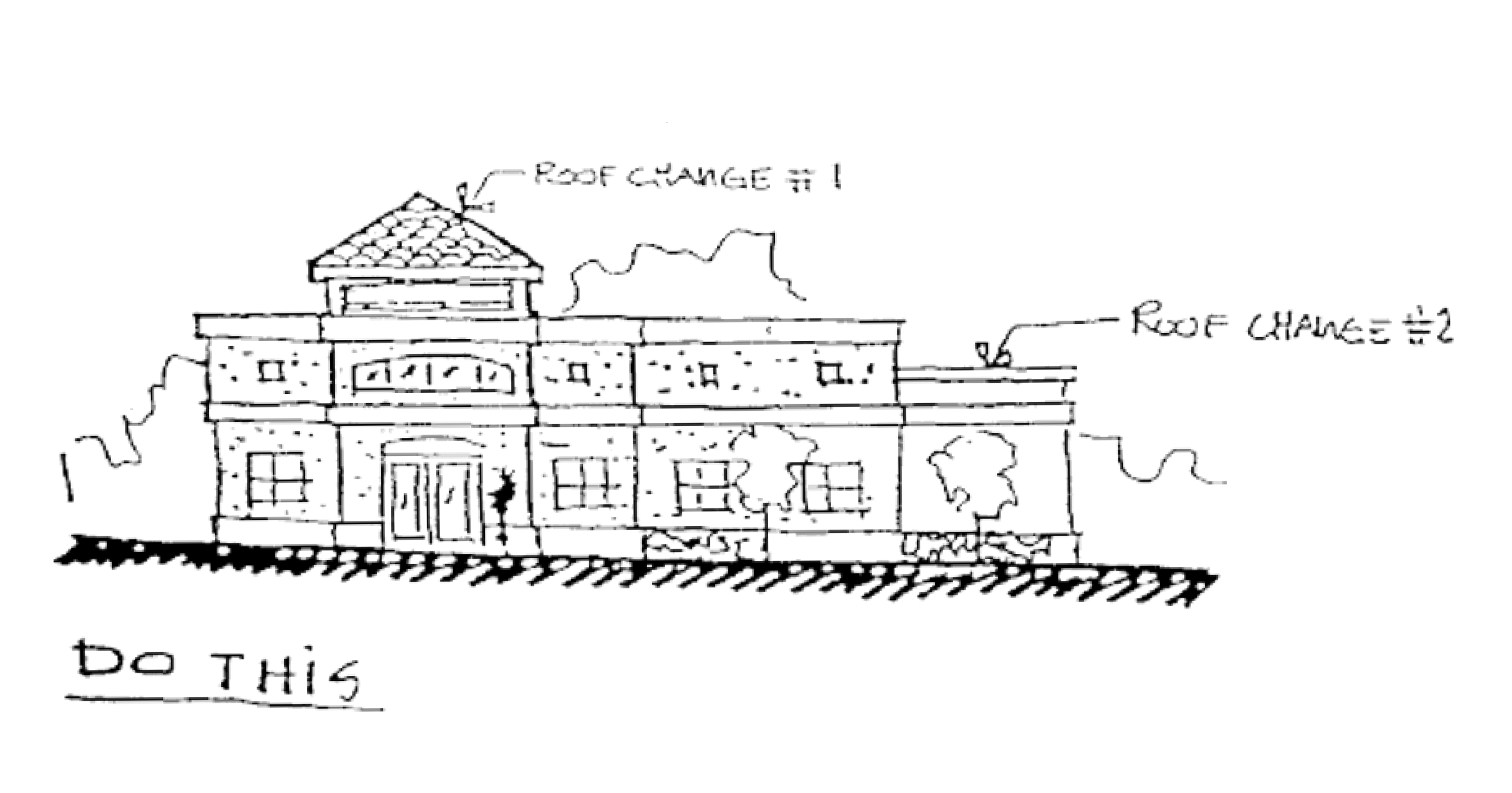
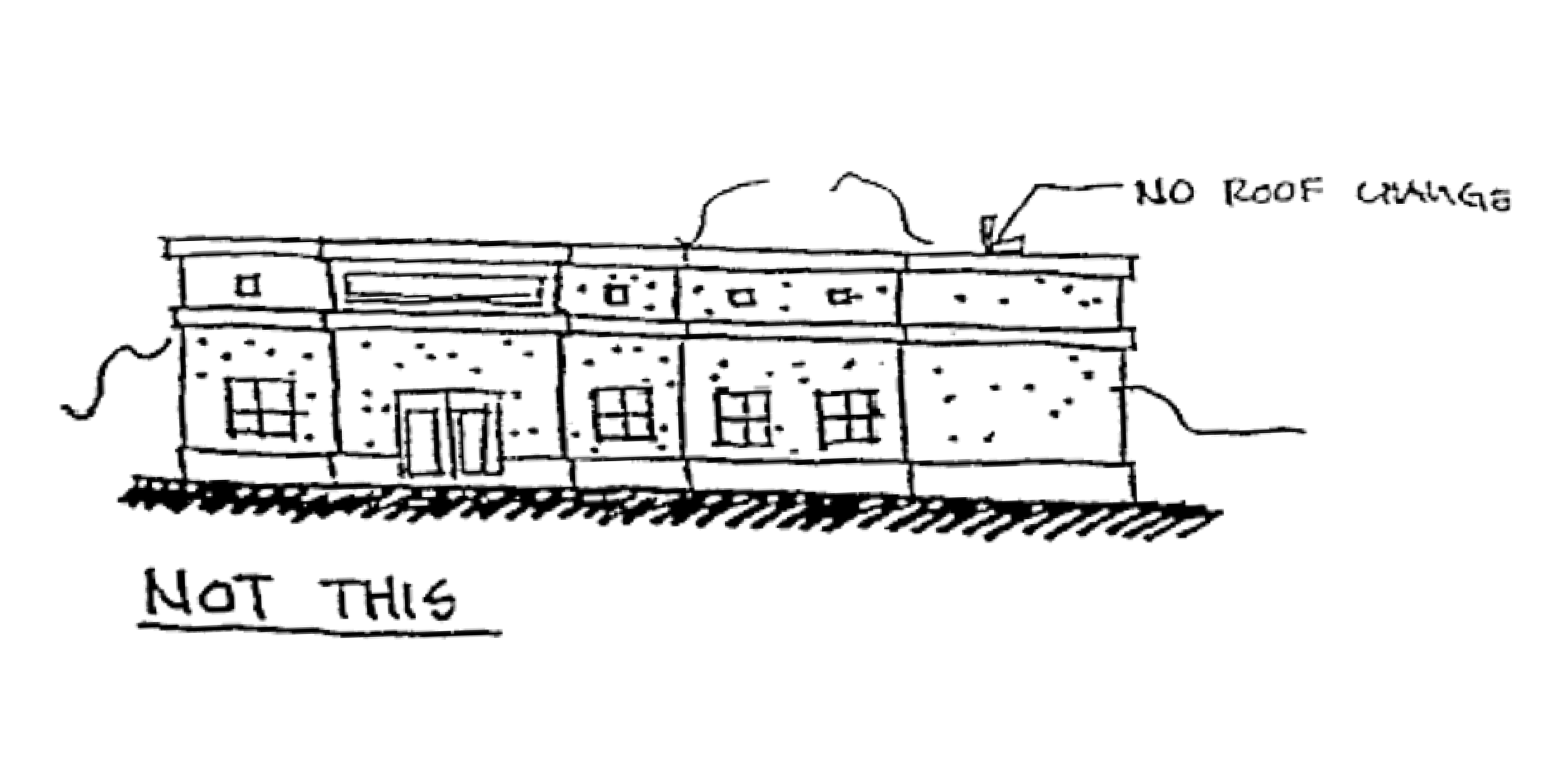
Illustration credit: Collier County, Florida, Land Development Code
4.26.
Figure 26 - Roof treatments.
The incorporation of multiple roof slope planes provides architectural detail and
visual interest. They must also be used to articulate a building's entrance and to
enhance pedestrian scale.
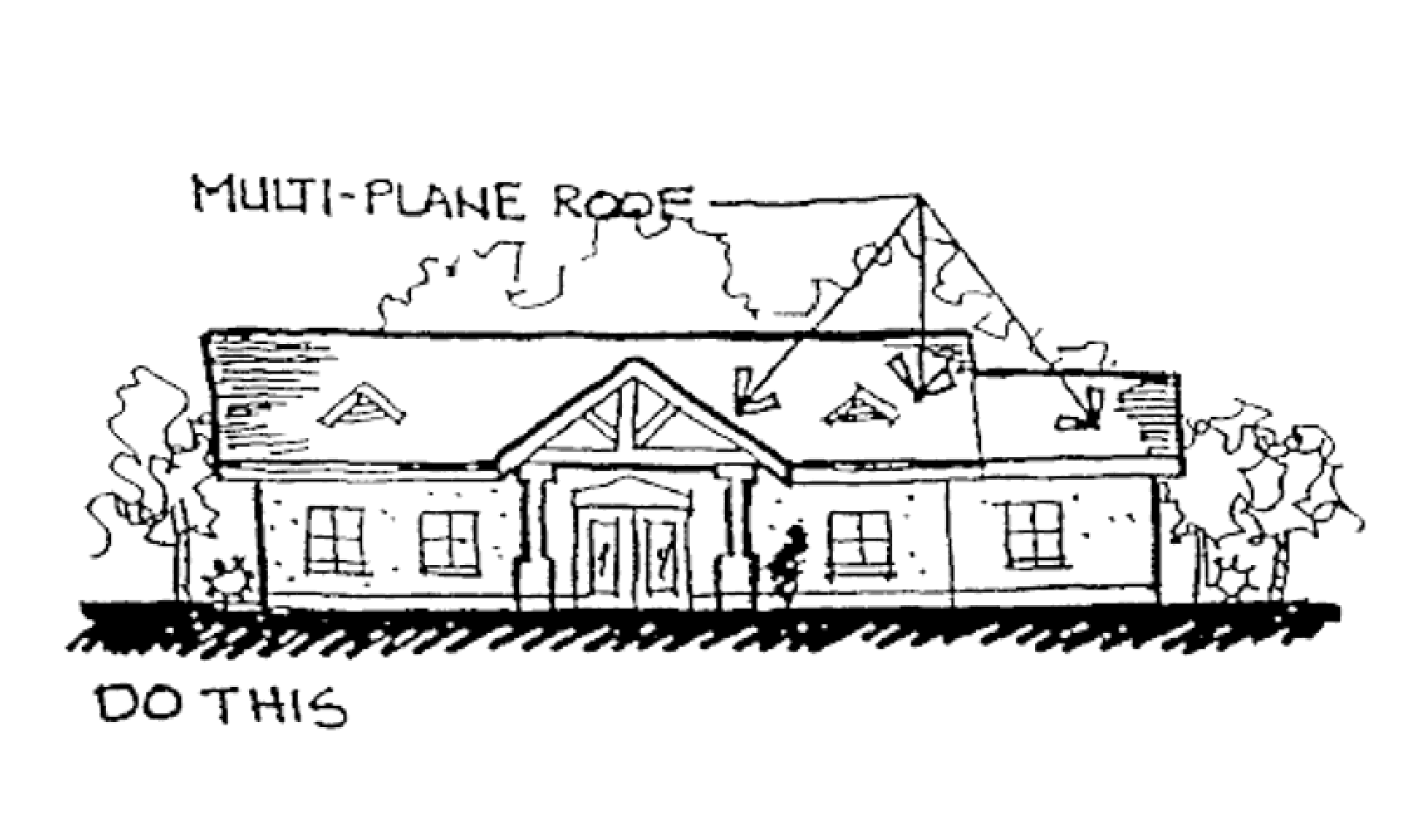
Illustration credit: Collier County, Florida, Land Development Code
5.
Compliance with the guidelines. All proposed nonresidential projects located within the CRA District shall demonstrate compliance with the site and building design standards outlined in this Manual. Compliance shall be demonstrated during the site and development plan and building plan review processes. The applicant shall submit both illustrative and narrative documentation to confirm and demonstrate compliance with the design guidelines outlined in this Manual.
APPENDIX I: - GENERIC SUBSTANCE LIST
Acid and basic cleaning solutions
Antifreeze and coolants
Arsenic and arsenic compounds
Bleaches, peroxides
Brake and transmission fluids
Brine solution
Casting and foundry chemicals
Caulking agents and sealants
Cleaning solvents
Corrosion and rust prevention solutions
Cutting fluids
Degreasing solvents
Disinfectants
Electroplating solutions
Explosives
Fertilizers
Fire extinguishing chemicals
Food processing wastes
Formaldehyde
Fuels and additives
Glues, adhesives and resins
Greases
Hydraulic fluid
Indicators
Industrial and commercial janitorial supplies
Industrial sludges and stillbottoms
Inks, printing and photocopying chemicals
Laboratory chemicals
Liquid storage batteries
Medical, pharmaceutical, dental, veterinary and hospital solutions
Mercury and mercury compounds
Metals finishing solutions
Oils
Paints, primers, thinners, dyes, stains, wood preservatives, varnishing and cleaning compounds
Painting solvents
PCBs
Pesticides and herbicides
Plastic resins, plasticizers and catalysts
Photo development chemicals
Poisons
Polishes
Pool chemicals
Processed dust and particulates
Radioactive sources
Reagents and standards
Refrigerants
Roofing chemicals and sealers
Sanitizers, disinfectants, bactericides and algaecides
Soaps, detergents and surfactants
Solders and fluxes
Stripping compounds
Tanning industry chemicals
Transformer and capacitor oils/fluids
Water and wastewater treatment chemicals
Sec. 9.A.1.10. - Applicability.
The City of Eagle Lake, Florida, may consider and enter into a development agreement with any person having a legal or equitable interest in real property located within the city limits, including the areas located within the Water and Sewer Intergovernmental Service Area Agreement with Polk County, Florida.
Sec. 9.A.1.20. - Public hearings.
1.
Before entering into, amending, or revoking a development agreement, one public hearing shall be conducted by the local planning agency for the purpose of preparing a recommendation on the development agreement to the city commission. The city commission shall, likewise conduct a public hearing for the purposes of receiving the recommendation of the local planning agency and determining whether or not to enter into the development agreement, revise or amend same, or revoke the agreement.
2.
Notice of intent to consider a development agreement shall be advertised approximately seven days before each public hearing in a newspaper of general circulation within Polk County, Florida.
3.
Notice of intent to consider a development agreement shall be mailed to all affected property owners prior to the public hearing before the local planning agency. The day, time, and place at which the second public hearing will be held shall be announced at the first public hearing.
4.
The notice shall specify the location of the land subject to the development agreement, the development uses proposed on the property, the proposed population densities, and the proposed building intensities and height and shall specify that a copy of the proposed agreement may be obtained from the office of the city clerk in city hall between the hours of 8:00 a.m. and 5:00 p.m.
Sec. 9.A.1.30. - Requirements of a development agreement.
A development agreement may provide that the entire development or any phase thereof be commenced or completed within a specific period of time. A development agreement shall include the following:
1.
Legal description of the land subject to the agreement, the names of its legal and equitable owners, and a title opinion of an attorney licensed in Florida or a certification by an abstractor or a title company showing that record title to the land as described is in the name of the person, persons, corporation, or entity party to this agreement;
2.
The duration of the agreement;
3.
The development uses permitted on the land, including population densities, and building intensities and height;
4.
A description of the public facilities that will service the development, including who shall provide such facilities; the date any new facilities, if needed, will be constructed; and a schedule to assure public facilities are available concurrent with the impacts of the development;
5.
A description of any reservation or dedication of land for public purposes;
6.
A description of all development permits approved or needed to be approved for the development of the land;
7.
A finding that the development permitted or proposed is consistent with the city comprehensive plan and land development regulations;
8.
A description of any conditions, terms, restrictions, or other requirements determined to be necessary by the city for the public health, safety, or welfare of its citizens; and
9.
A statement indicating that the failure of the agreement to address a particular permit, condition, term, or restriction shall not relieve the developer of the necessity of complying with the law governing said permitting requirements, conditions, terms, or restrictions.
Sec. 9.A.1.40. - Duration and relationship to the comprehensive plan.
1.
The duration of a development agreement shall not exceed ten years, but may be extended by mutual consent of the city and the developer, subject to a public hearing before the city commission in accordance with section 163.3225, F.S.
2.
No development agreement shall be effective or be implemented by the city unless the comprehensive plan and any plan amendments implementing or related to the agreement are found to be in compliance with state law by the Department of Community Affairs.
3.
A development agreement and authorized development shall be consistent with the city comprehensive plan and land development regulations.
Sec. 9.A.1.50. - Laws governing a development agreement.
1.
The city comprehensive plan and land development regulations in effect at the time of execution of the development agreement shall govern the development of the land for the duration of the development agreement.
2.
The city may apply subsequently adopted comprehensive plan amendments and amended provisions of the land development regulations to a development that is subject to a development agreement only if the city commission has held a public hearing in accord with section 163.3225, F.S. and determined:
A.
They are not in conflict with the comprehensive plan and land development regulations governing the development agreement and do not prevent development of the land uses, intensities, or densities in the development agreement;
B.
They are essential to the public health, safety, or welfare, and expressly state that they shall apply to a development that is subject to a development agreement;
C.
They are specifically anticipated and provided for in the development agreement;
D.
The city demonstrates that substantial changes have occurred in pertinent conditions existing at the time of approval of the development agreement; or
E.
The development agreement is based on substantially inaccurate information supplied by the developer.
Sec. 9.A.1.60. - Review of a development agreement.
The City of Eagle Lake shall review land subject to the development agreement every 12 months on the anniversary thereof to determine if good faith compliance with the terms of the development agreement has been demonstrated. If there has been a failure to comply with the agreement, the city commission may revoke or modify the agreement. For each annual review conducted during years six through ten of a development agreement, the review shall be incorporated into a written report which shall be submitted to the parties to the agreement and the Department of Community Affairs.
Sec. 9.A.1.70. - Amendment or cancellation.
A development agreement may be amended or cancelled by mutual consent of the parties to the agreement or by their successors in interest.
Sec. 9.A.1.80. - Recording and effectiveness.
The development agreement shall be recorded with the Polk County Clerk of Court within 14 days after the adoption of the agreement and a copy of the recorded development agreement shall be sent to the Department of Community Affairs within 14 days after the agreement is recorded. A development agreement shall not become effective until it is recorded with the Polk County Clerk of Court and until 30 days after having been received by the Department of Community Affairs. The burdens of the development agreement shall be binding upon, and the benefits of the agreement shall inure to, all successors in interest to the parties to the agreement.
Sec. 9.A.1.90. - Modification to comply with subsequent laws.
If state or federal laws are enacted after the execution of a development agreement which are applicable to and preclude the parties' compliance with the terms of a development agreement, such agreement shall be modified or revoked as is necessary to comply with the relevant state or federal laws.
Sec. 9.B.1.10. - Purpose.
The concurrency management system (CMS) is designed to quantify the impact of any proposed development or expansion to an existing development for which a development order is required, based upon adopted level of service for a roadway, sanitary sewer, solid waste, drainage, potable water, and parks/recreation public facility or other service. The most current available information and data regarding the above public facilities shall be utilized for concurrency evaluations. No final development order shall be approved unless adequate public facilities and services are available to mitigate the concurrent impact of a proposed development as determined by the concurrency management system and the comprehensive plan.
Sec. 9.B.2.10. - Level of service standards.
1.
Prior to the issuance of development orders and permits, the city shall determine that acceptable levels of service can be maintained for public facilities and services located within the area for which the city has authority to issue development orders and permits. For the purposes of establishing concurrency, public facilities and services include the following for which level of service standards have been adopted pursuant to chapter 9J-5, F.A.C.
A.
Roads, rule 9J-5.007(3)(c)1.
B.
Sanitary sewer, rule 9J-5.011(2)(c)2.a.
C.
Solid waste, rule 9J-5.011(2)(c)2.b.
D.
Drainage, rule 9J-5.011(2)(c)2.c.
E.
Potable water, rule 9J-5.011(2)(c)2.d.
F.
Parks and recreation, rule 9J-5.014(3)(c)4.
G.
Mass transit, rule 9J-5.008(3)(c)1., if applicable.
2.
The capital improvements element of the comprehensive plan sets forth a financially feasible plan which demonstrates how the city can achieve and maintain the adopted level of service standards.
3.
In analyzing and establishing level of service standards for state roads, the city shall, to the maximum extent feasible as determined by the city, adopt level of service standards for such roads that are compatible with the level of service standards established by the Florida Department of Transportation for such roads.
Sec. 9.B.2.20. - Minimum requirements for concurrency.
A concurrency management system is hereby developed and adopted to ensure that public facilities and services needed to support development are available concurrent with the impacts of such developments.
1.
Potable water, sewer, solid waste, and drainage. For potable water, sewer, solid waste, and drainage; at a minimum, the provisions in the comprehensive plan shall be met to satisfy the concurrency requirement:
A.
The necessary facilities and services are in place at the time a development permit is issued; or
B.
A development permit may be issued subject to the condition that the necessary facilities and services will be in place when the impacts of the development occurs; or
C.
The necessary facilities are under construction at the time a permit is issued; or
D.
The necessary facilities and services are guaranteed in an enforceable development agreement that includes the provisions of rules 9J-5.005(2)(a)1-3, and this chapter. An enforceable development agreement may include, but is not limited to, development agreements pursuant to section 163.3220, F.S., or an agreement or development order issued pursuant to chapter 380, F.S. The agreement must guarantee that the necessary facilities and services will be in place when the impacts of the development occur.
2.
Parks and recreation. For parks and recreation; the developer may satisfy the concurrency requirement by complying with the standards in Rules 9J-5.0055(2)(a)1-4, or by meeting the standards contained in the comprehensive plan to ensure that the following standards will be met:
A.
At the time the development permit is issued, the necessary facilities and services are the subject of a binding executed contract which provides for the commencement of the actual construction of the required facilities or the provision of services within one year of the issuance of the development permit; or
B.
The necessary facilities and services are guaranteed in an enforceable development agreement which requires the commencement of the actual construction of the facilities or the provision of services within one year of the issuance of the applicable development permit. An enforceable development agreement may include, but is not limited to, development agreements pursuant to section 163.3220, F.S., or an agreement or development order issued pursuant to chapter 380, F.S.
3.
Roads. For roads designated in the comprehensive plan, the developer may satisfy the concurrency requirement by complying with the standards in Rules 9J-5.0055(2)(a)1-4 and (2)(b)1 and 2. In addition, in areas in which the city has committed to provide the necessary public facilities and services in accordance with its five-year schedule of capital improvements, the city may satisfy the concurrency requirements for roads by the adoption and implementation of a concurrency management system based upon an adequate capital improvements program and schedule and adequate implementing regulations which, at a minimum, include the following provisions:
A.
A capital improvements element and a five-year schedule of capital improvements which, in addition to meeting all of the other statutory and rule requirements, must be financially feasible. The capital improvements element and schedule of capital improvements may recognize and include transportation projects included in the first three years of the applicable, adopted Florida Department of Transportation five-year work program.
B.
A five-year schedule of capital improvements which must include both necessary facilities to maintain the adopted levels of service standards to serve the new development proposed to be permitted and the necessary facilities required to eliminate those portions of existing deficiencies which are a priority to be eliminated during the five-year period under the city's schedule of capital improvements pursuant to rule 9J-5.016(4)(a)1. Provide further, however, that the city may not assess impact fees against a developer for remediating existing deficiencies.
C.
A realistic, financially feasible funding system based on currently available revenue sources, shall be adequate to fund the public facilities required to serve the development as authorized by the development order and development permit and which public facilities are included in the five-year schedule of capital improvements.
D.
A five-year schedule of capital improvements shall include the estimated date of commencement of actual construction and the estimated date of project completion.
E.
A five-year schedule of capital improvements must demonstrate that the actual construction of the road facilities and the provision of services are scheduled to commence on or before the third year of the five-year schedule of capital improvements.
F.
A provision that a plan amendment would be required to eliminate, defer, or delay construction of any road facility or service which is needed to maintain the adopted level of service standard and which is listed in the five-year schedule of capital improvements.
G.
A requirement the city must adopt development regulations which, in conjunction with the capital improvements element, ensure that development orders and permits are issued in a manner that will assure that the necessary public facilities and services will be available to accommodate the impact of that development.
H.
A provision that a monitoring system shall be adopted which enables the city to determine whether it is adhering to the adopted level of service standards and its schedule of capital improvements and that the city has a demonstrated capability of monitoring the availability of public facilities and services.
I.
A clear designation within the adopted comprehensive plan of those areas within which facilities and services will be provided by the city with public funds in accordance with the five-year schedule of capital improvements.
4.
In determining the availability of services or facilities, a developer may propose and the city may approve developments in stages or phases so that facilities and services needed for each phase will be available in accordance with the standards required by rules 9J-5.0055(2)(a), (2)(b) and (2)(c).
5.
For the requirements of rules 9J-5.0055(2)(a), (2)(b), and (2)(c), the city must develop guidelines for interpreting and applying level of service standards to applications for development orders and permits and determining when the test for concurrency must be met. The latest point in the application process for the determination of concurrency is prior to the approval of an application for a development order or permit which contains a specific plan for development, including the densities and intensities of development.
Sec. 9.B.3.10. - General.
The concurrency management system was enacted effective March 1, 1991. All applications for development orders that are pending or submitted subsequent to March 1, 1991, are subject to the concurrency management system. A development order refers to any building permit, zoning approval, subdivision approval (including either preliminary or final plat approval), site plan approval, impact statement approval, special exception, variance, or land use amendment. Once a development order for a particular development expires, so does the concurrency certification.
Sec. 9.B.3.20. - Extra-territorial services.
Adopted water and sewer levels of service shall be maintained in the unincorporated areas of the county where these facilities are provided by the city if a determination of concurrency or similar action is either required or requested from the county. The city may enter into an interlocal agreement with the county with respect to the administration or enforcement of concurrency requirements for potable water and/or sewer facilities, in accordance with Florida law.
Sec. 9.B.3.30. - Annexation.
If land is annexed into the city and, prior to annexation, was subject to development orders approved by the county, then the last development order issued by the county shall continue to comply with the county concurrency requirements and any subsequent development orders issued by the city. However, the developer, property owner, or their agent(s) may request at the time of annexation that the property be subject to the provisions of the requirements contained in the city concurrency management system. For any land subject to this paragraph, any development orders which are issued by the city after five years of the date of annexation shall be subject to the provisions of the city concurrency management system.
Sec. 9.B.3.40. - Exemptions.
Development permits for construction of a single-family dwelling unit on an individual lot or parcel in solitary ownership and additions to or the erection of structures in which the addition or erection does not exceed 1,000 square feet and are utilized for nonresidential purposes are deemed to be exempt from the concurrency rule. An exemption determination shall be issued to any land owner whose property is classified as being exempt from the concurrency provisions of this chapter. However, the city shall maintain capacity demand records for all such construction and combine such data with that required for monthly and annual updates.
Sec. 9.B.3.50. - Transferability.
An exemption determination, certificate of concurrency, or reserved capacity may be transferred from one property owner to another, but not from one parcel of land to another.
Sec. 9.B.4.10. - Provisions.
Receipt of a certification of concurrency shall constitute proof that public facilities are or will be available, consistent with adopted levels of service and conditions set forth in this chapter and shall specify the public facilities and services which are to be constructed, timing of construction, and responsibility for construction. Certification of concurrency shall reserve capacity in the public facilities which are available, until the certificate of concurrency is fulfilled, amended, or expires.
Sec. 9.B.5.10. - Provisions.
An amendment to a certificate of concurrency shall be required in order to amend any development order for which such certification has been made, if the amendment would increase or decrease the demand for any public facility or service. The amendment of the certification shall require evaluation and reservation of capacity only for any additional demand for public facilities and services which would be created by the amendment to the development order. Furthermore, the amendment to the certification shall be approved if the amendment to the development order is exempt from concurrency requirements in accordance with the provisions of this chapter.
Sec. 9.B.6.10. - General.
Except as provided otherwise, no development order for which application is submitted to the city after the effective date of these regulations shall be approved unless public facilities are or will be available to serve a proposed development, such that the adopted levels of service are maintained concurrent with the impacts of the proposed development. In order to determine the availability of public services for a development, the following conditions shall be met, given the proposed timing and phasing of the proposed development.
Sec. 9.B.6.20. - Infrastructure.
For potable water, sewer, solid waste, and drainage, which are required improvements according to the subdivision regulations:
1.
The necessary facilities and services are in place at the time a development permit is issued; or
2.
A development permit is issued subject to the condition that the necessary facilities and services will be in place when the impacts of the development occur; or
3.
The necessary facilities are under construction at the time a permit is issued; or
4.
The necessary facilities and services are guaranteed in an enforceable development agreement that includes the provisions of [sections] 9.B.6.20(1)—9.B.6.20(3) of this chapter. An enforceable development agreement may include, but is not limited to, development agreements pursuant to section 163.3220, F.S., or an agreement or development order issued pursuant to chapter 380, F.S. The agreement shall guarantee that the necessary facilities and services will be in place when the impacts of the development occur.
Sec. 9.B.6.30. - Parks and recreation.
For parks and recreation, the concurrency requirement may be satisfied by complying with the standards set forth in section 9.B.6.20(1)—(4) immediately above, or by complying with the following standards:
1.
At the time the development permit is issued, the necessary public facilities and services are the subject of a binding executed contract which provides for the commencement of the actual construction of the required public facilities or the provision of services within one year of the issuance of the development permit; or
2.
The necessary public facilities and services are guaranteed in an enforceable development agreement which requires the commencement of the actual construction of the public facilities or the provision of services within one year of the issuance of the applicable development permit. An enforceable development agreement may include, but is not limited to, development agreements pursuant to section 163.3220, F.S., or an agreement or development order issued pursuant to chapter 380, F.S.
Sec. 9.B.6.40. - Streets.
For roads designated in the adopted comprehensive plan, the city may ensure the standards of concurrency requirements by complying with the standards set forth in section 9.B.6.20(1)—(4) above.
Sec. 9.B.7.10. - Level of service.
The capital improvements element (CIE) of the city's comprehensive plan serves as the baseline standard for the concurrency management system. The CIE establishes level of service standards for each public facility or service and proposes a schedule for funding applicable improvements to these facilities. Once the comprehensive plan is adopted, the city shall maintain the level of service standards established in the capital improvements element and related elements of the comprehensive plan. The following level of service (LOS) standards have been adopted by the city:
TABLE 9.B.7.10(a):
LEVEL OF SERVICE STANDARDS
*See traffic circulation map for specific street designations.
TABLE 9.B.7.10(b):
SPACE STANDARDS WHEN UNIT FACILITY IS PROVIDED
*The improvements required by these standards shall be implemented when the population of the city reaches the absolute numerical threshold for each identified numerical recreation facility.
TABLE 9.B.7.10(c):
STANDARDS FOR SPECIAL FACILITIES*
Sec. 9.B.8.10. - City resources.
1.
All departments and agencies that provide and maintain public facilities or services in the city shall be requested by the administrative official to provide data and information that will be necessary to make concurrency determinations.
2.
Primary service providers are considered departments within the city that have a direct responsibility for maintaining a public facility or provide a public service. These departments will provide specific information on existing usage, system capacity, generation factors, and the status of planned facility expansions. The data and information provided by these departments will be the basis for determining how much capacity is available for new development while maintaining the adopted level of service standards. Primary service providers are:
TABLE 9.B.8.10(a):
PRIMARY SERVICE PROVIDERS
3.
Secondary service providers are those entities outside the city that have a role in providing or maintaining a public facility or service in the city. These entities shall be requested to provide the city with evaluations on how their operating conditions and future plans impact the city's adopted level of service standards. The information gathered from these entities will be long range in nature and less specific than information gathered from the primary service providers. Secondary service providers include:
TABLE 9.B.8.10(b):
SECONDARY SERVICE PROVIDERS
Sec. 9.B.8.20. - Monitoring system.
1.
The city shall maintain written or computerized records of all public facility and service capacities or volumes which are committed for developments as a result of development orders issued by the city. This process will require coordination between the service providers and the administrative official in order to establish and maintain an accurate accounting system that systematically tracts development approvals. At a minimum, the monitoring process must ensure that each service provider accounts for the impact and demand generated by all development orders issued by the city.
2.
Accountability shall be established by reserving capacity from the total available capacity for all approved development orders. Once capacity is reserved for a specific development, it cannot be allocated to another development. Capacity reservations shall be renewed no later than June 30 on a yearly basis in order for facility improvements or services to be entered into or accounted for in the annual budgetary process. Upon the expiration of a development order with concurrency standing which is not constructed or deemed by the city as having been abandoned by an applicant, the capacity allocated to that proposed development shall be deleted. Deleted capacity shall then be available for use, reservation, or allocation to other proposed developments on a first come, first serve basis. A priority "waiting list" shall be established for the purpose of allocating deleted capacity. Reserved capacity may be transferable from one property owner to another, but not from one lot or parcel of land to another. When determining how much capacity is available for new proposed developments, the city shall take into account all capacity that is reserved for approved development orders.
3.
Development orders that remain valid through March 1, 1991 (as determined by the city) shall remain exempt from meeting concurrency requirements, but the development impacts will be added cumulatively to existing capacities and volumes for each affected public facility or service in order to establish total committed and available capacity. Development orders issued by governmental jurisdictions outside the city shall also be accounted for if the development order is issued within the service area of a city service provider.
Sec. 9.B.8.30. - Annual system adjustment.
At a minimum, the database component shall be updated as a part of the city's annual schedule of capital improvements update. Necessary adjustments include: updating information generated by service providers, making changes (deletions or reservations) to available facility capacities, adding or deleting capital projects, using new or enhanced revenue sources, moving projects ahead of schedule, and delaying projects due to revenue shortfalls. The administrative official must ensure that all relevant information is updated on a regular basis by conducting a monthly inventory of development orders issued by the city and requiring primary service providers to maintain current records.
Sec. 9.B.9.10. - General.
1.
Once a specific development application is accepted as complete, the following information must be documented and verified:
A.
Type of development proposed;
B.
Number of new or additional dwelling units or nonresidential units;
C.
Densities or intensities of uses;
D.
Types of uses or units; and
2.
Specific boundaries of the proposed development.
3.
This information shall be collected from the original development application submitted by the applicant. The administrative official will then calculate the projected public facility and service demands of the proposed development and identify the public facilities and/or services that will be affected.
4.
If the demands generated by the proposed development, when deducted from the available capacity, fall below the minimum established level of service standard thresholds, the proposal will be found in compliance and capacity will be reserved for needed facilities or services. If a proposed development causes established thresholds to exceed the adopted LOS standards, the administrative official shall prepare an impact statement and forward copies to all affected primary service providers. Primary service providers will review impact statements and determine how much capacity will be available to service the proposed development.
Sec. 9.B.9.20. - City staff review.
1.
The city shall determine, in consultation with the appropriate service provider, if and when adequate public facilities and/or services will be available to serve the proposed development. If the city determines, after consultation with the service provider that adequate public facilities and/or services exist to serve the proposed development, the administrative official shall render a finding of concurrence and capacity will be reserved for that particular facility and/or service for the proposed development, for a period not to exceed one calendar year from the date of such determination. If the city determines, after consultation with the service provider that public facilities and/or services will not be available or will result in a degradation of adopted levels of service, the administrative official shall render a finding of non-concurrency.
2.
The administrative official shall afford each service provider consulted, 30 days to render an opinion of concurrency. If the application complies with the service provider's level of service standards or can be mitigated to comply, the administrative official shall issue a certificate of concurrency and capacity shall be reserved. The certificate of concurrency shall specify the public facilities which are to be constructed, timing of construction, and responsibility for construction. The reservation shall be valid for a period of one year after issuance of a development order. An applicant may renew the reservation on an annual basis, with the renewal period to be no later than June 30 of each year. All capacity reservations granted between January and June of each year shall not be required to renew the reservation until the following June.
3.
In case of a finding of non-concurrency, the applicant shall be so notified and then may pursue the mitigation process.
Sec. 9.B.9.30. - Mitigation.
1.
If levels of service standards fall below thresholds due to the demands generated by the proposed development, the applicant may pursue one of the following mitigation options:
A.
Phasing the development in accordance with planned facility improvements;
B.
Scaling back or reducing the development size in accordance with available public facilities and/or services; or
C.
Executing an enforceable development agreement which guarantees the construction of all necessary public facilities and/or services at the time the impacts of development occur.
2.
If a mitigation solution is agreed upon by the city and applicant, the administrative official shall render a finding of compliance and capacity will be reserved. If an applicant cannot or will not mitigate the project's impacts in a manner acceptable to the city, the administrative official will render a finding of noncompliance and a final development order shall be withheld. An applicant may appeal the city's finding and determination to the city commission.
Sec. 9.B.9.40. - Payment in lieu of dedication.
The petitioner may be permitted, after review and recommendation by the city staff, to dedicate or make payment-in-lieu of dedication, as part of the development order, for the purpose of securing easements for public utility systems, setbacks and rights-of-way for traffic circulation systems, and provisions for open space and for meeting applicable level of service standards.
Sec. 9.B.9.50. - Replacement.
Any proposed development that will utilize components of the existing infrastructure system that has been determined to need replacement within five years of the date of issuance of the development order to maintain the applicable adopted level of service standards, shall be required to replace or pay the proportionate costs for replacement.
Sec. 9.B.9.60. - Appeals.
The decision of the administrative official is final but may be appealed in writing to the city commission by either the applicant or the city staff by filing notice of the appeal within 30 calendar days of the rendering of the administrative official's decision. The city commission may affirm, modify, or uphold the decision of the administrative official or remand the matter to the administrative official for further review. The decision of the city commission shall be based upon the concurrency requirement and accepted engineering and planning principles and shall be rendered within 45 days after the close of the city commission hearing on the appeal.
Sec. 9.C.1.10. - Purpose and intent.
The purpose of this chapter is to establish a method whereby the impacts of development on transportation facilities can be mitigated by the cooperative efforts of the public and private sectors, to be known as the proportionate fair-share program, as required by and in a manner consistent with section 163.3180(16), F.S.
Sec. 9.C.1.20. - Findings.
The city commission finds and determines that transportation capacity is a commodity that has a value to both the public and private sectors and the city's proportionate fair-share program:
1.
Provides a method by which the impacts of development on transportation facilities can be mitigated by the cooperative efforts of the public and private sectors;
2.
Allows developers to proceed under certain conditions, notwithstanding the failure of transportation concurrency, by contributing their proportionate fair-share of the cost of a transportation facility;
3.
Contributes to the provision of adequate public facilities for future growth and promotes a strong commitment to comprehensive facilities planning, thereby reducing the potential for moratoria or unacceptable levels of traffic congestion;
4.
Maximizes the use of public funds for adequate transportation facilities to serve future growth, and may, in certain circumstances, allow the city to expedite transportation improvements by supplementing funds currently allocated for transportation improvements in the capital improvements element (CIE) of the City of Eagle Lake Growth Management Plan (city plan);
5.
Is consistent with section 163.3180(16), F.S., the concurrency management system (CMS) set forth in chapter 9 of the city plan and the provisions of the land development regulations of the city.
Sec. 9.C.1.30. - Applicability.
The proportionate fair-share program shall apply to all developments in the city that have been notified of a lack of capacity to satisfy transportation concurrency on a transportation facility in the city concurrency management system (CMS), including transportation facilities maintained by FDOT or another jurisdiction that are relied upon for concurrency determinations, pursuant to the requirements of section 9.C.1.40. The proportionate fair-share program does not apply to developments of regional impact (DRIs) using proportionate fair-share under section 163.3180(12), F.S., or to developments exempted from concurrency as provided in section 163.3180(4)(b), 5(b) and 5(c), F.S., as well as section II (3)(d) of chapter 9, concurrency management system, of the city plan, and appendix B of the city's land development regulations, except to the extent there is any conflict between the above-referenced city plan and land development regulations provisions, and section 163.3180(6), F.S. In the case of such a conflict, the Florida Statute provisions shall control. The proportionate fair-share program does not preclude applicants from funding transportation improvements pursuant to a development agreement to meet concurrency requirements as set forth in section 9.C.1.90.
Sec. 9.C.1.40. - General requirements.
1.
An applicant may choose to satisfy the transportation concurrency requirements of the city by making a proportionate fair-share contribution, pursuant to the following requirements:
A.
The proposed development is consistent with the comprehensive plan and applicable land development regulations.
B.
The five-year schedule of capital improvements in the city capital improvement element of the comprehensive plan or the long-term schedule of capital improvements for an adopted long-term concurrency management system includes the construction phase of a transportation improvement(s) that, upon completion, will satisfy the requirements of the city's transportation CMS.
2.
The city may choose to allow an applicant to satisfy transportation concurrency through the proportionate fair-share program by adding an improvement (construction phase) to the CIE or adopted long-term CMS that will satisfy the requirements of the city's transportation CMS. For the purposes of the proportionate fair-share program, no capacity road project shall be added to the CIE unless any required alignment study or a project development and environmental (PD&E) study has been completed with an endorsed build alternative.
3.
To implement this option, the city shall adopt, by resolution or ordinance, a commitment to add the improvement to the five-year schedule of capital improvements in the CIE or long-term schedule of capital improvements for an adopted long-term CMS no later than the next regularly scheduled update. To qualify for consideration under this section, the proposed improvement must be reviewed by the appropriate city, and determined to be financially feasible pursuant to section 163.3180(16)(b)1, F.S., consistent with the comprehensive plan, and in compliance with the provisions of this chapter. Any improvement project proposed to meet the developer's fair-share obligation must meet the design standards of the jurisdiction with maintenance responsibility for the subject transportation facility.
Sec. 9.C.1.50. - Memorandum of understanding on proportionate fair-share program.
The city shall coordinate with the Florida Department of Transportation, Polk Transportation Planning Organization, and other local governments or agencies as appropriate to implement the provisions of the proportionate fair-share program. Appropriate provisions for intergovernmental coordination will be detailed in a memorandum of understanding on the proportionate fair-share program (MOU), and the city shall coordinate with the signatory parties to ensure that mitigation to impacted facilities is based on comprehensive and consistent transportation data.
Sec. 9.C.1.60. - Application process.
1.
Upon notification of a lack of capacity to satisfy transportation concurrency, the applicant shall also be notified in writing of the opportunity to satisfy transportation concurrency through the proportionate fair-share program pursuant to the requirements of section 9.C.1.40.
2.
Prior to submitting an application for a proportionate fair-share agreement, a pre-application meeting shall be held to discuss eligibility, e.g., project status in CIE, application submittal requirements, potential mitigation options, and related issues. If the impacted facility is on the SIS, or any state transportation facility, then the FDOT will be notified and invited to participate in the pre-application meeting.
3.
Eligible applicants shall submit an application to the city that includes an application fee as set by the city commission and the following:
A.
Name, address, and phone number of owner(s), developer and agent;
B.
Property location, including parcel identification numbers;
C.
Legal description and survey of property;
D.
Project description, including type, intensity, and amount of development;
E.
Phasing schedule, if applicable;
F.
Description of requested proportionate fair-share mitigation method(s);
G.
Copy of concurrency application;
H.
Copy of the project's traffic study or traffic impact analysis; and
I.
Location map depicting the site and affected road network.
4.
The city shall review the application and determine whether or not the application is sufficient and complete within 15 days. If an application is determined to be insufficient, incomplete, or inconsistent with the general requirements of the proportionate fair-share program as indicated in section 9.C.1.40, then the applicant will be notified in writing of the reasons for such deficiencies within ten business days of submittal of the application. If such deficiencies are not remedied by the applicant within 30 days of receipt of the written notification, then the application will be deemed abandoned. The city commission may, in its discretion, grant an extension of time not to exceed 60 days to cure such deficiencies, provided that the applicant has shown good cause for the extension and has taken reasonable steps to effect a cure.
5.
Pursuant to section 163.3180(16)(e), F.S., proposed proportionate fair-share mitigation for development impacts to facilities on the SIS requires the concurrence of the FDOT. The applicant shall submit evidence of an agreement between the applicant and the FDOT for inclusion in the proportionate fair-share agreement.
6.
When an application is deemed sufficient, complete, and eligible, the applicant shall be advised in writing and a proposed proportionate fair-share obligation and binding agreement will be prepared by the city or the applicant with direction from the city and delivered to the appropriate parties for review, including a copy to the FDOT for any proposed proportionate fair-share mitigation on a SIS facility, or any state transportation facility, no later than 60 days from the date at which the applicant received the notification of a sufficient application and no fewer than 45 working days prior to the city commission meeting when the agreement will be considered.
7.
The city shall notify the applicant regarding the date of the commission meeting when the agreement will be considered for final approval. No proportionate fair-share agreement will be effective until approved by the city commission.
Sec. 9.C.1.70. - Determining proportionate fair-share obligation.
1.
Proportionate fair-share mitigation for concurrency impacts may include, without limitation, separately or collectively, private funds, contributions of land, and construction and contribution of facilities as provided in section 163.3180(16)(c), F.S.
2.
A development shall not be required to pay more than its proportionate fair-share. The fair market value of the proportionate fair-share mitigation for the impacted facilities shall not differ based on the form of mitigation as provided in section 163.3180(16)(c), F.S. (Contributors of private fund, land, or facility construction.)
3.
The methodology used to calculate an applicant's proportionate fair-share obligation shall be as provided for in section 163.3180(12), F.S., as follows:
A.
The cumulative number of peak hour, peak direction trips from the complete build out of the proposed development, or buildout of the stage or phase being approved, that are assigned to the proportionate share program segment divided by the change in the peak hour maximum service volume (MSV) of the proportionate share program segment resulting from construction of the proportionate share program improvement, multiplied by the anticipated cost of the proportionate share project. In this context, cumulative does not include project trips from previously approved stages or phases of development.
This methodology is expressed by the following formula:
Proportionate Fair-Share = + [((Development Trips;sub\sub;)/(SV Increase;sub\sub;)] x Cost;sub\sub;)]
Where:
+ = Sum of all deficient links proposed for proportionate fair-share mitigation for a project;
Development Trips;sub\sub; = Those trips from the stage or phase of development under review that are assigned to roadway segment "i" and have triggered a deficiency per the concurrency management system (CMS);
SV Increase;sub\sub; = Service volume increase provided by the eligible improvement to roadway segment "i";
Cost;sub\sub; = Adjusted cost of the improvement to segment "i". Cost shall include the cost of all project phases (preliminary engineering or alignment study, design, rights-of-way acquisition and construction) in the years said phases will occur with all associated costs.
4.
The cost of the proportionate fair-share project shall be determined by the maintaining jurisdiction.
5.
The value of right-of-way dedications used for proportionate fair-share payment shall be subject to the approval of the maintaining jurisdiction. No value shall be assigned to right-of-way dedications required under ordinance or as a condition of development approval.
Sec. 9.C.1.80. - Impact fee credit for proportionate fair-share mitigation.
1.
Upon adoption of a transportation project within the CIE, the city shall create and maintain a list of transportation projects funded by road impact fees under the CIE. If the subject improvement is contained in the current CIE and funded in part or whole by road impact fees, the proportionate fair-share contributions shall be applied as a credit against road impact fees.
2.
Road impact fee credits for the proportionate fair-share contribution will be determined when the transportation impact fee obligation to the city is calculated for the proposed development. Road impact fees owed by the applicant will be reduced per the proportionate fair-share agreement as they become due per the city impact fee ordinance. If the applicant's proportionate fair-share obligation is less than the development's anticipated road impact fee for the specific stage or phase of development under review, then the applicant or its successor must pay the remaining impact fee amount to the city pursuant to the requirements of the city's impact fee ordinance. This requirement shall not affect county-imposed road impact fees.
3.
The proportionate fair-share obligation is intended to mitigate the transportation impacts of a proposed development at a specific location. As a result, any road impact fee credit based upon proportionate fair-share contributions for a proposed development cannot be transferred to any other location unless provided for within the local impact fee ordinance, if any.
4.
The amount of traffic impact fee credit for a proportionate fair-share contribution may be up to, but shall not exceed, the project's proportionate fair-share amount and will be determined based on the following formula:
Credit =
[(Cost of Proportionate Share Project) ;ds; (Total Cost of All Projects in Applicable Impact Fee District)] × (Total Project Traffic Impact Fee Liability)
Where:
Cost of projects shall include the cost of all project phases in the year said phases will occur with all associated costs. Credit shall be calculated based on multiple proportionate share projects, if applicable.
Sec. 9.C.1.90. - Proportionate fair-share agreements.
1.
Upon execution of a proportionate fair-share agreement and satisfying other concurrency requirements, an applicant shall receive a city certificate of concurrency approval. Should the applicant fail to apply for building permits within the timeframe provided for in the city concurrency certificate, then the project's concurrency vesting shall expire, and the applicant shall be required to reapply. Once a proportionate fair-share payment for a project is made and other impact fees for the project are paid, no refunds shall be given. All payments, however, shall run with the land.
2.
Payment of the proportionate fair-share contribution for a project and other road impact fees not subject to an impact fee credit shall be due and must be paid within 60 days of the effective date of the proportionate fair-share agreement. The effective date shall be specified in the agreement and shall be the date the agreement is approved by the city commission or its designee.
3.
All developer improvements accepted as proportionate fair-share contributions must be completed within three years of the issuance of the first building permit for the project which is the subject of the proportionate fair-share agreement and be accompanied by a security instrument that is sufficient to ensure the completion of all required improvements. It is the intent of this section that any required improvements be completed within three years of the issuance of the first building permit for the project which is the subject of the proportionate fair-share agreement.
4.
Dedication of necessary right-of-way for facility improvements pursuant to a proportionate fair-share agreement must be completed prior to the effective date of the proportionate fair-share agreement.
5.
Any requested change to a development project subsequent to issuance of a development order shall be subject to additional proportionate fair-share contributions to the extent the change would generate additional traffic that would require mitigation.
6.
Applicants may submit a letter to withdraw from the proportionate fair-share agreement at any time prior to the execution of the agreement. The application fee and any associated advertising costs to the city will be nonrefundable.
Sec. 9.C.1.100. - Appropriation of fair-share revenues.
1.
Proportionate fair-share revenues shall be placed in the appropriate project account for funding of scheduled improvements in the city's CIE, or as otherwise established in the terms of the proportionate fair-share agreement. At the discretion of the local government having jurisdiction over the relevant transportation facility subject to the proportionate fair-share agreement, and with the concurrence of the local government issuing the development order, proportionate fair-share revenues may be used for operational improvements prior to construction of the capacity project from which the proportionate fair-share revenues were derived. These operational improvements shall be consistent with, the construction of the capacity project. Proportionate fair-share revenues may also be used as the 50 percent local match for funding under the FDOT Transportation Regional Incentive Program (TRIP).
2.
In the event a scheduled facility improvement is removed from the CIE, then the revenues collected for its construction may be applied toward the construction of another improvement within that same corridor or sector that would mitigate the impacts of development.
Sec. 9.C.1.110. - Severability, conflicts, effective date.
1.
If any section, subsection, sentence, clause, or phrase of this ordinance is for any reason held illegal, invalid, or unconstitutional by the decision of any court or regulatory body of competent jurisdiction, such decisions shall not affect the validity of the remaining portions hereof. The commission hereby declares that it would have passed this ordinance and each section, subsection, sentence, clause, and phrase hereof, irrespective of the fact that any one or more sections, subsections, sentences, clauses, or phrases be declared illegal, invalid or unconstitutional.
2.
In the event of any conflict between this article 1, appendix C of the city land development regulations, and any other article in appendix C, or any other provision contained in the city Code or land development regulations, then this article shall control. This article shall be construed in a manner consistent with section 163.3180, F.S.
3.
This article shall be effective immediately upon adoption.
Sec. 9.D.1.10. - General.
1.
Upon the effective date of the land development regulations, any use of land or water to be established or changed, and any building, structure, or tract of land constructed, developed, or used for any allowable or permitted use whether a principal use or as accessory use in any zoning district now or hereafter established shall comply with the performance standards herein, as applicable, to such use zoning district in which it is located.
2.
When any existing use, building, or other structure is extended, enlarged, or reconstructed, the performance standards shall be applied to such extension, enlargement, or reconstruction of such building or other structure.
Sec. 9.D.1.20. - Standard manuals and measuring devices.
The following devices and instruments standardized and certified by the American Standard Association shall be used when measurements are required for the purpose of ascertaining conformity with these regulations:
TABLE 9.D.1.20(a):
STANDARDIZED AND CERTIFIED DEVICES AND INSTRUMENTS
Sec. 9.D.1.30. - Charts and manuals.
The following charts and/or manuals shall be used as performance criteria:
TABLE 9.D.1.30(a):
PERFORMANCE CRITERIA CHARTS AND MANUALS
Sec. 9.D.2.10. - Certification.
Prior to issuing a development order for any proposed use, the administrative official shall ascertain to the maximum extent feasible, that the proposed use will conform with the applicable provisions of this chapter. In making such determination, the administrative official may, if necessary, require certification by a State of Florida registered professional engineer that the proposed use will meet the performance criteria contained herein.
Sec. 9.D.3.10. - General methods of measurement.
1.
For the purpose of measuring the intensity and frequency of sound, sound level meters and octave band filters meeting the criteria of the American Standards Association shall be employed. The location, placement, and timing of measurements shall be arranged insofar as possible to exclude background noise emanating from off the premises where the measurement is to be taken. A reasonable correction factor shall be applied in circumstance where off-premises background noise can not be eliminated to compensate for such off-premise background noises.
2.
Sounds of short duration, such as those from forge hammers, punch presses, and metal shears, which cannot be measured accurately with the sound level meter, shall be measured with an impact noise filter of a type equivalent to that manufactured by the General Electric Company or the H.H. Scott Company, in order to determine the peak value of impact. For sounds so measured, the sound pressure level set forth in Table 9.D.3.20(a) may be increased by six decibels. All sound measuring devices shall be used in accordance with manufacturer's instructions.
Sec. 9.D.3.20. - Sound measurement in industrial districts.
In industrial districts, decibel levels from any use shall not exceed at any point at or beyond the district boundary lines the maximum set out in Table 9.D.3.20(a); and provided further that, where an industrial district adjoins any district generally permitting residences, institutional uses including schools, or hotels and motels, maximums at or beyond the industrial district boundary shall be reduced seven decibels from levels indicated in Table 9.D.3.20(a) for hours between 8:00 a.m. and 6:00 p.m. and ten decibels between 6:00 p.m. and 8:00 a.m.
TABLE 9.D.3.20(a):
MAXIMUM PERMITTED SOUND PRESSURE LEVEL (IN DECIBELS)
IN INDUSTRIAL DISTRICTS
*Where an industrial district adjoins any district generally permitting residences, institutional uses including schools, or hotels and motels, the sound pressure level in decibels must be reduced.
Sec. 9.D.3.30. - Sound measurement in all other districts.
In all other districts, decibel levels from any activity shall not exceed at any point at or beyond the lot lines the maximum set forth in Table 9.D.3.30(a); provided further that, where such districts generally permit residences, institutional uses including schools, or hotels and motels, maximums at or beyond the lot line shall be reduced seven decibels from the levels indicated in Table 9.D.3.20(a) for the hours between 8:00 a.m. and 6:00 p.m. and ten decibels between 6:00 p.m. and 8:00 a.m.
TABLE 9.D.3.30(a):
MAXIMUM PERMITTED SOUND PRESSURE LEVEL (IN DECIBELS)
IN ALL DISTRICTS OTHER THAN INDUSTRIAL DISTRICTS
*Where an industrial district adjoins any district generally permitting residences, institutional uses including schools, or hotels and motels, the sound pressure level in decibels must be reduced.
• Source: U.S. Department of Labor noise regulations
Sec. 9.D.3.40. - Creating noise for purpose of advertising prohibited.
Within the city limits, no person shall blow any horn or whistle, ring any bell, or use any other device whereby a noise is produced for the purpose of advertising any business, occupation, or article or for the purpose of attracting attention to such advertisement, and no person shall cause or procure the same to be done within the city.
Sec. 9.D.3.50. - Other noises.
All unnecessary or unauthorized noises and annoying vibrations, including animal noises, shall be prohibited. Sound produced by emergency warning systems, such as fire whistles or sirens and the like, are exempt from the provisions of this chapter.
Sec. 9.D.4.10. - Provisions.
1.
For the purpose of measuring vibration, a three component measuring system recognized as standard for such purpose shall be used. The location, placement, and timing of measurements shall be arranged insofar as possible to exclude vibrations emanating from off the premises which is the subject of the measurement, or a reasonable correction factor reasonable shall be applied to compensate for off-premises vibrations.
2.
In industrial zoning districts, steady state or impact vibrations from any use shall not exceed at any point measured at or beyond the lot lines the levels set forth in Table 9.D.4.10(a).
TABLE 9.D.4.10(a):
MAXIMUM PERMITTED STEADY STATE IMPACT
VIBRATION DISPLACEMENT (IN INCHES)
Sec. 9.D.5.10. - Provisions.
To protect and enhance the air quality of the city, all sources of air pollution shall comply with rules set forth by the Environmental Protection Agency (Code of Federal Regulations, title 40) and the Florida Department of Environmental Protection (Florida Administrative Code, chapter 17-2) as amended. No person shall operate a regulated source of air pollution without a valid operating permit issued by the Department of Environmental Protection.
1.
Air pollution emissions shall be tested and results reported in accordance with techniques and methods adopted by the Florida Department of Environmental Protection and submitted to the state. These tests shall be carried out under the supervision of the state and at the expense of the person responsible for the source of pollution.
2.
All development orders shall contain provisions that require construction activity to keep dust and dirt particles from blowing from the construction site through the use of approved liquid treatment or other acceptable methods in order to minimize emissions generated by the construction activity.
Sec. 9.D.6.10. - Provisions.
No operation involving radiation emission hazards shall be conducted in any zoning district which violates the regulations and standards established in title 10, chapter 1, part 20, Code of Federal Regulations, "Standards for Protection Against Radiation," and as amended.
Sec. 9.D.7.10. - Provisions.
In any district, no odor shall be permitted at any lot line exceeding the lowest amount set forth in Table III, "Odor Thresholds," of chapter 5, "Physiological Effects," of the Air Pollution Abatement Manual of the Manufacturing Chemists Association (manual), as amended, for the compounds therein described. For compounds not described in Table III, odor thresholds may be established by methods indicated in chapter 5 of the manual, and no odor shall be permitted at any lot line exceeding the amount determined by the application of such methods.
Sec. 9.D.8.10. - Provisions.
In all zoning districts, the concentration of toxic or noxious odors shall not exceed, at any point on or beyond any lot line, 1/10 of the maximum allowable concentration set forth in section 12-20 of ICR 12 measured with the A.D.I.
Sec. 9.D.9.10. - Provisions.
Disposal of all liquids, including water, used in any way or for any purpose whatsoever shall be done in such a manner as to not harm the potable water supplies of the city and county, the Floridan Aquifer, or any of the bodies of water in the city and county. All applicable requirements of the Department of Environmental Protection (DEP), the Environmental Protection Agency (EPA), the Southwest Florida Water Management (SWFWMD) and other federal, state, county, and city regulatory agencies shall be met in all zoning districts.
Sec. 9.D.10.10. - Provisions.
In all districts, no use, activity, or process shall be conducted which produces electromagnetic interference with normal radio or television reception off the premises where the activity is conducted.
Sec. 9.D.11.10. - Provisions.
1.
In all districts except industrial districts, any activity producing humidity in the form of steam or moist air, or producing heat or glare, shall be carried on in such a manner that the steam, humidity, heat, or glare is not perceptible at any lot line.
2.
In industrial districts, any activity producing humidity in the form of steam or moist air, or producing heat or glare, shall be carried on in such a manner that the steam, humidity, heat, or glare is not perceptible at any industrial district line.
Sec. 9.D.12.10. - Provisions.
In all districts in which the storage, use, or manufacture of combustible hazardous or explosive materials or their handling or stockpiling is permitted, the following regulations shall apply:
1.
Incombustible to moderate burning solid materials may only be stored, used, or manufactured, subject to the fire code and land development regulations.
2.
Free burning and intense burning solid materials may be stored, used, or manufactured only within completely enclosed buildings having incombustible walls and protected throughout by an automatic fire extinguishing system. The requirement for an automatic fire extinguishing system may be waived by the administrative official in those cases where the introduction of water to a burning substance would cause additional hazard.
3.
Flammable liquids or materials which produce flammable or explosive vapors or gases are permitted in industrial districts, subject to storage, handling, and use requirements of the "Standards of National Board of Fire Underwriters for Storage, Handling, and Use of Flammable Liquids," National Board of Fire Underwriters Pamphlet No. 30, June, 1959. When flammable gases are stored, used, or manufactured, and measured in cubic feet, the quantity in cubic feet (S.T.P.) permitted shall not exceed 300 times the quantities listed in Table 9.D.12.10(a) where the factor 300 is the volume in cubic feet occupied by one gallon of water.
4.
In districts other than industrial in which storage or use of flammable materials is permitted, they shall be stored in accordance with the limits of Table 9.D.12.10(a):
TABLE 9.D.12.10(a):
TOTAL CAPACITY OF FLAMMABLE MATERIALS
PERMITTED (IN GALLONS)
Sec. 9.D.13.10. - Provisions.
In an industrial zoning district, outside operations and storage normally associated with and incidental to a permitted use shall be permitted; provided, however, that when abutting a residential, institutional, or commercial district not divided by a street or alley, such outside operations and storage shall be effectively screened from such district by a solid wall or fence a minimum of six feet high, to provide a visual barrier.
Sec. 9.D.14.10. - Administration and enforcement general.
1.
Determinations necessary for administration and enforcement of performance standards range from those which can be made by a reasonable person using normal sensory organs and no equipment to those which require highly technical competence and complex equipment.
2.
Where determinations can reasonably be made by the administrative official using equipment and personnel normally available to the city or obtainable without extraordinary expense, such determinations shall be made before notice of violation is issued.
3.
Where technical complexity or extraordinary expense make it unreasonable for the city to maintain personnel or equipment necessary for making compliance determinations, the procedures herein set out shall be employed to protect individuals from the arbitrary administration and enforcement of these regulations, and for protecting the general public from unnecessary costs for administration and enforcement.
Sec. 9.D.14.20. - Administration and enforcement without great expense.
Where a determination of violation of these performance standards can be made by the administrative official using equipment and personnel available to the city or obtainable without extraordinary expense, determination of violation shall be made. The administrative official shall take or cause to be taken lawful action as provided by this chapter to eliminate such violation. Failure to obey lawful orders concerning cessation of violation shall be punishable as provided in this chapter.
Sec. 9.D.14.30. - Administration and enforcement involving highly skilled personnel and expensive instruments.
Where a determination of violation of performance standards entails the use of highly skilled personnel and expensive instrumentation not ordinarily available to the city, and when, in the considered judgment of the administrative official a violation exists, the procedure for making such determination shall be as follows:
1.
Notice. The administrative official shall give written notice, by certified mail, return receipt requested, or other means ensuring a signed receipt for such notice, to those responsible for the alleged violation. Such notice shall describe the particulars of the alleged violation and the reasons why the administrative official believes there is a violation in fact, and shall require an answer or a correction of the alleged violation to the satisfaction of the administrative official within a reasonable time limit set by the administrative official but in no case more than ten days. The notice shall state, and it is hereby declared, that failure to reply or to correct the alleged violation to the satisfaction of the administrative official within the time limit set constitutes admission of violation. The notice shall further state that upon request of those to whom it is directed, technical determinations as described in the appropriate portions of this chapter will be made; and that if violation as alleged is found, costs of the determinations shall be charged against those responsible, in addition to such other penalties as may be appropriate; and that if it is determined that no violation exists, costs of the determinations will be paid by the city.
2.
Correction of violation within time limit. If, within the time limit set, there is no reply but the alleged violation is corrected to the satisfaction of the administrative official, he shall note "Violation Corrected" on his copy of the notice and shall retain it as part of his records, taking such other action as may be warranted by the circumstances of the case.
3.
No correction; no reply. If there is no reply within the time limit set, thus establishing admission of violation as provided in subsection 9.D.14.30(1) above and the alleged violation is not corrected to the satisfaction of the administrative official within the time limit set, he shall take or cause to be taken such action as warranted by continuation of an admitted violation after notice to cease.
4.
Reply requesting extension of time. If a reply is received within the time limit set indicating that an alleged violation will be corrected to the satisfaction of the administrative official, but that more time is required than was granted by the original notice, the administrative official may grant an extension of time, if he deems such extension is warranted in the circumstances of the case, and if such extension will not, in his opinion, cause imminent peril to life, health, or property. In acting on such requests for extension of time, the administrative official shall in writing state his reasons for granting or refusing to grant the extension and shall transmit the same by certified mail, return receipt requested, or other means ensuring a signed receipt, as provided in subsection 9.D.14.30(1) above, to those to whom original notice was sent. Such extension(s) shall have a maximum 30-day time limit.
5.
Reply requesting technical determination. If a reply is received within the time limit set requesting technical determinations as described in the appropriate provisions of this article and if the alleged violations continue, the administrative official may call in properly qualified experts to make the determinations. If expert findings indicate violation of the performance standards, the costs of the determinations shall be assessed against the properties or persons responsible for the violations, in addition to such other penalties as may be appropriate under division I, chapter 3 of the land development regulations. If no violation is found, costs of the determination shall be paid by the city without assessment against the properties or persons involved.
Sec. 9.E.1.10. - General provisions.
In order to protect the public health, safety, and welfare of the residents of the city, the construction related safety standards/codes and Florida Statutes listed below, as published by the Southern Building Code Congress International, Inc., the National Electrical Code, and the State of Florida are adopted by reference, and as may subsequently be lawfully amended, are made a part of these land development regulations by city ordinance and codified herein.
The construction safety standards/codes hereby adopted by the city commission of the City of Eagle Lake include the following:
1.
Standard Building Code, 1997 Edition;
2.
Standard Plumbing Code, 1997 Edition;
3.
Standard Gas Code, 1997 Edition;
4.
Standard Mechanical Code, 1997 Edition;
5.
Standard Fire Prevention Code, 1997 Edition;
6.
Standard Swimming Pool Code, 1985 Edition;
7.
Standard Unsafe Building Abatement Code, 1985 Edition;
8.
National Electrical Code, 1999 Edition;
9.
Chapter 553.14, Florida Statutes, Water Conservation Act;
10.
Chapter 553, part V, Florida Statutes, Accessibility by Handicapped Persons; 1997 Ed. with 1999 revisions;
11.
Chapter 633.025, Florida Statutes, Minimum Fire Safety Standards;
12.
Life Safety Code, NFPA 101, 1991 Edition; and
13.
Florida Hurricane Code, 1997 Edition.
Sec. 9.E.1.20. - Adoption of amendments to standard building code.
There are hereby adopted codified amendments to the duly adopted Standard Building Code, 1997 Edition, which are made a part of the land development regulations.
Sec. 9.E.1.30. - Plumbing code.
There are hereby adopted codified amendments to the duly adopted Standard Plumbing Code, 1997 Edition, which are made a part of the land development regulations.
Sec. 9.E.1.40. - Gas code.
There are hereby adopted codified amendments to the duly adopted Standard Gas Code, 1997 Edition, which are made a part of the land development regulations.
Sec. 9.E.1.50. - Mechanical code.
There are hereby adopted codified amendments to the duly adopted Standard Mechanical Code, 1997 Edition, which are made a part of the land development regulations.
Sec. 9.E.1.60. - Fire prevention code.
There are hereby adopted codified amendments to the duly adopted Standard Fire Prevention Code, 1997 Edition, which are made a part of the land development regulations.
Sec. 9.E.1.70. - Swimming pool code.
There are hereby adopted codified amendments to the duly adopted Standard Swimming Pool Code, 1985 Edition, which are made a part of the land development regulations.
Sec. 9.E.1.80. - Unsafe building code.
There are hereby adopted codified amendments to the duly adopted Standard Unsafe Building Abatement Code, 1985 Edition, which are made a part of the land development regulations.
Sec. 9.E.1.90. - Electrical code.
There are hereby adopted codified amendments to the duly adopted National Electrical Code, 1990 Edition, which are made a part of the land development regulations.
Sec. 9.E.1.100. - Water conservation code.
There are hereby adopted amendments to the duly adopted chapter 553.14, Florida Statutes, Water Conservation Act, which is made a part of the land development regulations.
Sec. 9.E.1.110. - Appeals.
The planning commission shall serve as the appellate body for all appeals applicable to the city construction-safety codes.
Sec. 9.F.1.10. - Intent.
The purpose of this chapter is to provide developers with design criteria and construction standards for specified improvements that, at a minimum, protect the consumer and the public in the investment for their future. The goals, objectives, and policies adopted as a part of the traffic circulation element of the comprehensive plan shall serve as the guiding principles for the articles and sections herein with regard to street network function, layout, and safety features and the associated systems that typically accompany street construction and improvements.
Sec. 9.F.1.20. - Design criteria for streets.
1.
The arrangement, character, extent, width, grade, and location of all streets shall conform to the future land use and traffic circulation elements of the comprehensive plan and shall be considered in their relation to existing and planned streets, to topographic conditions, public convenience and safety, and in their appropriate relation to the proposed uses of the land to be served by such streets.
2.
Where streets are not identified in the future land use and traffic circulation element, the arrangement of streets in a subdivision or development shall either:
A.
Provide for the continuation of appropriate projection of existing principal streets in surrounding areas; or
B.
Conform to a plan for the neighborhood approved or adopted by the city commission to meet a particular situation where topographic or other conditions make continuance or conformance to existing streets impracticable.
3.
Minor streets shall be so laid out that their use by through traffic will be discouraged.
4.
Where a subdivision or development abuts or contains an existing or proposed arterial street, the city commission may require marginal access streets, reverse frontage with buffer plantings contained in a non-access reservation along the rear property line, or such other treatment as may be necessary for adequate protection when such street serves residential uses and to afford separation of through and local traffic.
5.
Where a subdivision or development borders on or contains a railroad right-of-way, or a limited access in highway right-of-way, the city commission may require a street approximately parallel to and on each side of such right-of-way, at a distance suitable for the appropriate use of the intervening land, as for park purposes in residential districts, or for commercial or industrial uses in appropriate districts. Distances involving rights-of-way shall also be determined with due regard for the requirements of approach grades and future grade separations.
6.
Reserve strips controlling access to streets shall be prohibited.
7.
Street jogs with center line offsets of less than 125 feet shall be prohibited.
8.
Except for private streets, a tangent at least 100 feet long shall be introduced between reverse curves on streets having radius less than 500 feet unless unusual circumstances dictate alternate standards approved by the city (consulting) engineer.
9.
Streets shall be laid out so as to intersect with other streets at approximate right angles. Streets shall have a minimum tangent of 100 feet at intersections unless otherwise approved.
10.
Property lines at street intersections shall be rounded with a minimum radius of 25 feet, or of a greater radius where the city commission may deem it necessary. The city (consulting) engineer may recommend comparable cutoffs or chords in place of round corners.
11.
Street right-of-way widths shall be as shown in the traffic circulation element and where not shown therein shall be not less than as follows in Table 9.F.120(a):
TABLE 9.F.120(a):
STREET RIGHT-OF-WAY WIDTHS
12.
Private streets shall have a minimum driving surface width of 20 feet for two way traffic and 12 feet for one way traffic, except as provided for herein, built according to the minor street construction standards. Private streets serving only one residence shall provide a minimum driving width of 12 feet. Private streets serving more than one but less than three residences shall provide a minimum driving width of 16 feet. Such streets shall not be maintained at public expense.
13.
Half streets shall be prohibited.
14.
Dead-end streets, designed to be so permanently, shall have a length no greater than 600 feet measured the full length of the right-of-way and shall be provided at the closed end with a turnaround having an outside roadway radius of at least 45 feet, and a street right-of-way radius of at least 50 feet or, within the above configurations, a "T" type turnaround may be provided.
15.
No street names shall be used which will duplicate or be confused with the names of existing streets, provided that where alignment is appropriate, new streets shall bear the names of existing street. Street names shall be subject to the approval of the city commission.
16.
Street grades, where feasible, shall not exceed five percent nor be less than 0.4 percent.
Sec. 9.F.2.10. - Design criteria for alleys.
1.
Alleys shall be provided in commercial and industrial districts, except that the city commission may waive this requirement where other definite and assured provision is made for service access, such as off-street loading, unloading, and parking consistent with and adequate for the uses proposed.
2.
The width of an alley shall be not less than 15 feet.
3.
Alley intersections and sharp changes in alignment shall be avoided, but where necessary, corners shall be rounded to a minimum radius of 20 feet to permit safe vehicular movement.
4.
Dead-end alleys shall be prohibited.
5.
Alleys shall be prohibited in residential areas except in circumstances where the city commission finds extension of alleys from commercial and industrial districts necessary.
Sec. 9.F.3.10. - Design criteria, and construction standards for curbs and gutters.
1.
The requirements for curbs and gutters will vary according to the function of the street, character of the area in which the street is located, and density of development. Raised curbs and gutters shall be required on all arterial and collector streets so indicated in the traffic circulation element. Minor and marginal access streets shall be provided with curbs according to their function, alignment, and site conditions. Curbs shall be required on all streets. Roadside swales shall be prohibited on all curbed streets. The developer shall provide adequate proof, by means of topography, percolation tests, drainage plans, and acceptable calculations that raised curbs are unnecessary to handle the surface drainage conditions prior to approval of Miami curbs by the city commission.
2.
In commercial developments, including shopping centers, or where other similar intensive urban uses exist or are anticipated, raised curbs shall be required on streets and in parking lots.
3.
Private streets shall be provided with curbs according to the conditions as stated in [section] 9.F.3.10(1), except that this shall apply only to areas where the existing or anticipated residential density of the area, within and surrounding the proposed subdivision or development served by a common street, equals or exceeds one dwelling unit per gross acre.
4.
Curbs shall be constructed of Portland cement and work shall comply with the Florida Department of Transportation Standard Specifications for Roads and Bridge Construction, latest edition.
Sec. 9.F.4.10. - Intent.
Streets designed in accordance with sound engineering principles to adequately handle anticipated traffic volumes shall be installed by the developer. The design shall include all streets within the limits of said subdivision or development, plus appropriate connections and alignments where necessary to maintain continuity with those streets adjoining the subdivision or project.
Sec. 9.F.4.20. - Street construction standards.
1.
Arterial streets. Arterial streets, as defined and identified in the traffic circulation element, shall have a minimum paved driving surface width of 12 feet per lane, according to the traffic circulation element requirements, with a minimum of 12 inches of sub-base at 40 LBR, eight inches compacted limerock stabilized base compacted to 98 percent modified proctor and 1½ inches of Type S-1 asphaltic concrete surface course. A two-foot-wide gutter with raised concrete curb shall be provided along the outer edges of the paved driving surface of arterial and collector streets.
2.
Collector streets. Collector streets, as defined and identified in the traffic circulation element, shall have a minimum paved driving surface width of 24 feet or 48 feet, according to the transportation element requirements, with a minimum of 12 inches of sub-base at 40 LBR, eight inches compacted limerock stabilized base compacted to 98 percent modified proctor with 1¼ inches of Type S-1 asphaltic concrete surface course. A two-foot-wide gutter with raised concrete curb shall be provided along the outer edges of the paved driving surface of arterial and collector streets.
3.
Minor and marginal access streets. Minor and marginal access streets shall have a minimum paved driving surface width of 22 feet with a minimum of eight inches of sub-base at 40 LBR, six inches compacted limerock stabilized base compacted to 98 percent modified proctor and 1¼ inches of Type S-1, S-3, or Type II asphaltic concrete surface course. Either a two-foot-wide gutter with raised concrete curb or Miami curb and gutter shall be provided along the outer edge of the paved driving surface.
4.
All of the above street paving widths are designed for use with no on-street parking. Where on-street parking is provided, an additional cross section width of 8.5 feet shall be added to the above required driving surface width for each added parking lane.
5.
The sub-base materials shall be high bearing value soil, sand-clay, limerock, shell, or other materials that are approved by the city (consulting) engineer and will meet the LBR requirements for type of street being constructed.
6.
Private streets and parking lots shall be constructed to meet the city's minor street construction standards in [section] 9.F.4.20(3), except that minimum width requirements shall be as provided for in [section] 9.F.1.20(12).
7.
Alleys shall be paved to a minimum driving surface width of 12 feet and constructed as for minor and marginal access streets, as provided in [section] 9.F.4.20(3) above.
8.
Radii of pavements at street intersections shall be not less than 25 feet at edge of pavement or face of curb lines. Where residential streets intersect collector or arterial streets, the minimum radius shall be not less than 35 feet.
9.
Cross sections of all streets, grading, and centerline gradients shall be according to plans and profiles approved by the city (consulting) engineer.
10.
The following general requirements shall apply to the clearing, grubbing, and grassing phases of construction:
A.
Only that portion of the right-of-way necessary for pavement and drainage facilities need be cleared and grubbed according to the requirements of the Florida Department of Transportation Standard Specifications for Road and Bridge Construction, latest edition. Florida native trees of four-inch caliper or greater trunk diameter shall be saved wherever they will not constitute a safety hazard, nor be defaced by utility construction, or be damaged by the required street construction. The administrative official shall require that trees to be saved, due to these requirements, be prominently marked and barricaded before the beginning of construction.
B.
All finished earth surfaces within public right-of-way shall be grassed according to the following criteria to prevent erosion and to improve the appearance of the completed work.
1.
Finished surfaces with ratios less steep than four horizontal to one vertical shall be grassed and mulched.
2.
Finished surfaces with ratios as steep as or steeper than 4:1 shall be sodded.
3.
All swales and retention/detention areas shall be sodded.
4.
All swale ditches with an average velocity exceeding two feet per second shall be sodded. In no case shall swale velocities exceed six feet per second for ditch slopes less than five percent and four feet per second for ditch slopes greater than five percent.
11.
Streets serving commercial developments or subdivisions and accessory parking areas shall be planned to connect with arterial or collector streets so as not to generate traffic on minor streets nor to provide principal access through residential developments. The intersections of driveways from parking areas with arterial or collector streets shall be located so as to cause the least possible interference with traffic movement on the street, and shall be located not less than 100 feet from the intersection of an arterial or collector street with any other street, and shall be spaced not less than 100 feet from each other. The city commission may require marginal access streets to provide maximum safety and convenience.
12.
Streets serving industrial development or subdivisions and accessory parking shall be planned to serve industrial areas exclusively and shall connect with arterial or collector streets so that no industrial traffic will be directed onto any residential street. The intersections of service streets from parking areas with arterial streets shall not be less than 100 feet from the intersection of the arterial street with any other street. Streets shall be planned to be extended to the boundaries of any adjoining land planned for industrial uses, except in the case of severe site conditions or limitations or if the city commission finds such extension is not in accord with the approved plan of the area to be served.
13.
Concrete paving or other alternative paving methods (i.e., interlocking pavers, paver brick, or similar systems) may be utilized if approved in advance by city staff. Concrete paving shall be designed according to the latest edition of the Florida Department of Transportation Design Standards for Rigid Paving. Developer shall submit calculations proving adequacy of any proposed alternate paving method to city staff.
14.
Storm drainage materials to be used shall be those materials acceptable to the Florida Department of Transportation (DOT), as listed in the current DOT standard specifications, and shall be installed in accordance with DOT regulations. The use and installation of such materials shall be subject to the review of the city engineer for adequacy in conformance with this chapter.
Sec. 9.F.5.10. - Sanitary sewerage.
TABLE 9.F.5.10(a):
SEWAGE FLOW ESTIMATE TABLE
AVERAGE DAILY FLOW (ADF)
1.
In the event that septic tanks or private sewerage plants are permitted in areas where public sanitary sewers are planned for later extension, such systems shall be located in such a manner as to facilitate later connection with public systems. All such private systems shall be required to connect to the city public system when the public system is within 600 feet, measured along public rights-of-way, of the private system.
2.
All sewer lines, with the exception of service laterals, shall be a minimum of eight inches in diameter and laid at a minimum slope of 0.4 percent. Where possible, sewer lines shall be oriented parallel to the centerline of the road right-of-way. In no case shall a lateral line be longer than 50 feet to the right-of-way. All sewer lines shall be extra strength vitrified clay pipe or PVC. PVC sewer pipe shall have a minimum standard dimensional ratio (SDR) of 35.
3.
All improvements as stated above shall be subject to approval of appropriate state agencies regarding minimum standards for guidance on sewerage and subdivision development.
Sec. 9.F.5.20. - Water: domestic and fire protection.
1.
All residential and nonresidential structures in subdivisions shall be connected to a public water supply.
2.
The city's latest standard details shall be minimum standards for guidance on constructing water lines. Fire hydrants shall be not more than 1,000 feet apart and no home shall be more than 500 feet from a fire hydrant measured along public rights-of-way in residential areas, or as may be determined by the fire chief. Fire hydrant spacing shall be decreased to 600 feet or a radius of not more than 300 feet apart along public rights-of-way or private drives within residential developments other than single-family detached dwellings. All fire hydrants shall be serviced by not less than six-inch water mains or lines. Specifications for fire hydrants and other portions of the fire protection water installation shall be as set forth by the American Water Works Association and shall be compatible with existing installations.
Sec. 9.F.5.30. - Underground utilities; electric, telephone and similar services.
1.
All residential subdivisions hereinafter developed under these regulations shall have all electric, telephone, and television cables placed underground. Such utility cables may be placed with random separation in the same trench according to the requirements of the city building, plumbing, and electrical codes. Street light standards shall have underground feed cables with no overhead lines being permitted. All underground electrical conductors, including secondary conductors, carrying more than 24 volts shall be in metal or PVC conduit. PVC conduit shall be laid with magnetic marking tape.
2.
All such underground utilities may be placed within the rights-of-way of the streets or, if impractical in a specific case, within utility easements at the side or rear lot lines within the subdivision. Such variation must be approved by the city engineer.
3.
Transformer pads, telephone, and television connection boxes and the like shall be placed within the right-of-way or utility easements. Such pads and boxes may be placed underground if adequate waterproofing containers and systems are used and are acceptable to the city engineer.
4.
Gas and water lines may be placed in the same trench with spacing to be regulated by city building, plumbing, gas, and electrical codes.
5.
Where overhead utility service is in place prior to platting of lots and will not be removed, the new lots immediately adjoining the existing service may be continued to be served from these overhead services.
6.
Each new subdivision or development, with public or private streets, shall have a minimum of one street light at the entrance, one at each street intersection and a minimum of one street light along the streets with a maximum spacing of 400 feet. Except as provided below, all street lights shall be installed on concrete poles with a high pressure sodium fixture with a minimum 70-watt lamp.
7.
All private developments planned and operated as a single entity, such as multiple family developments, apartments, townhouses, condominiums, commercial, industrial, or any other private land developments shall be required to provide street lighting adequate for the safety and well being of the occupants. Amount and number of streetlights shall be determined by the administrative official, city staff, and developer.
8.
The developer may submit plans for light standards other than concrete and if determined by city staff to provide lighting equal to requirements of [section] 9.F.5.30(6) above, the city commission may grant approval of an alternate system of street lighting for the subdivision or development.
Sec. 9.F.5.40. - Sidewalks.
See division IV, chapter 5 of the land development code for information.
Sec. 9.F.5.50. - Inspection; accountability; right of access; material testing.
In order to assure that the public is being properly served as construction progresses and that improvements meet city minimum construction standards, all construction within the subdivision or development shall be subject to the following requirements:
1.
The city commission may, if conditions warrant such action, require that improvements be designed and constructed to higher standards than are incorporated herein.
2.
The city shall be notified in advance of proposed construction of streets and utility improvements or stages thereof within the subdivision or development. During construction, designated city inspectors shall visit the project at appropriate stages to assure that construction is in accordance with plans and specifications, and may halt construction until defects or defaults are corrected to their satisfaction. Should construction continue without city approval, the contractor and developer shall be subject to legal action as provided for in the land development regulations.
3.
All work performed under these regulations shall meet the minimum requirements of the Florida Department of Transportation Standard Specifications for Road and Bridge Construction, latest edition, where applicable unless stated otherwise herein. These specifications are intended to govern the equipment, materials, construction methods, and quality control of the work, unless otherwise provided for herein. The provisions of these specifications pertaining to methods of measurement and basis of payment are not applicable to the land development regulations.
4.
The developer shall furnish the city with certificates of compliance executed by the manufacturer or supplier of any materials which are incorporated into the work. Such certificates shall indicate full compliance with the applicable specifications.
5.
The developer shall furnish mix designs for all job-mixed material including bituminous pavements, soil cement bases, Portland cement concrete or other materials to be used in the work. Such mix designs shall be prepared by a recognized testing laboratory and signed by a registered engineer.
6.
The developer shall employ a recognized testing firm to perform such field inspections and tests as may be required to ensure that the work is performed in compliance with the specifications. Prior to acceptance of the completed work by the city, the laboratory shall furnish to the city a certificate attesting that the work has been inspected and tested in accordance with accepted good practice, and that it meets or exceeds the specified requirements.
7.
Tests for the subgrade bearing capacity and compaction shall be located no more than 500 feet apart and shall be staggered to the left, right, and on the centerline of the roadway. When multiple failures indicate that conditions warrant additional testing, the developer shall be responsible for performing such additional testing as may be required by the city.
8.
The city reserves the right to inspect and/or test any work, and to reject any workmanship and/or materials found to be deficient. The city shall bear the costs of such inspections, except that in case of failure of the work and/or materials to conform to the specifications, the developer shall bear the costs of all removal, replacement, and/or corrective work required and of those inspections and tests required to prove the adequacy of such removal, replacement, and/or correction.
9.
All sanitary sewer lines shall be tested for infiltration/exfiltration using a leakage method. In addition, all sewer lines, including laterals, shall be inspected with a video camera and a VHS format tape of the inspection provided to the city.
10.
All water lines shall be disinfected in accordance with health department standards. All water lines shall be pressure tested at least two hours for leakage in accordance with recognized test methods.
Sec. 9.F.5.60. - Extensions to properties within and outside the city.
1.
The following provides a means by which the City of Eagle Lake's utility systems may be connected to or extended. In general, developers are responsible for all cost and installation of utility systems within and adjacent to the proposed development, except for portions of individually metered service installations.
2.
Procedures for requesting utility service. The extension of the City of Eagle Lake utility services to properties lying outside and non-contiguous to the corporate limits of the City of Eagle Lake shall be considered by the city commission. The extension of utility service to properties lying outside, but contiguous to the corporate city limits shall be considered by the city manager. The extension of utility service to properties lying within and outside the corporate city limits, but contiguous to existing utility lines, may be considered by the city manager. The below procedure shall be utilized in all applications for utility service to properties within and outside the corporate limits of the city.
A.
The petitioner (owner of record) of the non-contiguous property to be served by the utility system must formally request that the city make city utility services available to the site. In order to initiate the request, the petitioner should contact the city manager and provide the following information in order for the administration to properly evaluate the request:
1.
A project location map and complete legal description of the subject property;
2.
Proof of ownership, e.g., a copy of certificate of title of the site;
3.
A comprehensive, itemized breakdown of the proposed land use intended for the subject site; and
4.
An estimate of the daily water and wastewater demands of the subject property. Unit consumption/generation rates shall be in accordance with city standards unless the developer can provide evidence and prove that other consumption/generation rates would be more applicable.
B.
For non-contiguous properties, the required information shall be provided to the city public works director at least ten days prior to the commission meeting at which the request for utility service is to be considered.
C.
The petitioner must execute a "Petition for Utility Service" before the city commission, or where applicable, the city manager, will consider the request. The execution of a "Petition for Utility Service" obligates the developer to construct the utility system in compliance with certain conditions:
1.
All utilities constructed within the subject property shall be in conformance with all applicable land development regulations, administration and procedures manual, city codes, specifications, and requirements.
2.
All costs associated with the extension of City of Eagle Lake utility services to the subject property are to be made at no expense to the City of Eagle Lake, except as provided below.
3.
Responsibility for installation. Where an extension will benefit other property owners and/or development and will be a utility system expansion identified in the five-year schedule of capital improvements of the comprehensive plan, the city may consider the following options for line extensions:
A.
The developer may prepay the entire cost of the extension. The developer will be reimbursed the extension cost from other users connecting to the line within a five-year period and/or from the developer's own impact fees. Such reimbursement shall be up to but not exceeding 100 percent of the certified cost of the extension.
B.
The city may pay the cost of the extension. The city may further require a letter of credit or other acceptable collateral provided by the developer guaranteeing the city reimbursement of the entire cost of the extension over the subsequent five-year period.
C.
The city and the developer may enter into a utility extension agreement requiring the developer to reimburse the city for the cost incurred by the city. Any portion of the facilities to be installed or materials supplied by the city must be labeled as such on the construction plans.
D.
Ninety percent of all extension fees (excluding the developer's fee) will be credited to the developer's debt for a five-year period. These extension fees are in addition to usual impact fees and connection fees.
E.
Said five-year period shall commence at the time of final acceptance by the city of the extension.
4.
Where an extension will not benefit other property owners and/or developments, and will not be a utility system expansion identified in the five-year schedule of capital improvements of the comprehensive plan, the developer shall be totally responsible for all installation costs within the development an/or adjacent to his property and all costs incurred except for that cost agreed upon by the city (see section 9.F.5.70) and except as noted below.
5.
Extensions will be of the city's minimum size or greater if needed by the developer.
6.
Where it is deemed by the city to be more feasible to serve a development with a new water or wastewater facility rather than by extending existing city utilities, the developer shall be responsible for the cost of constructing the required facilities. Water and/or wastewater treatment plants may be designed by the developer's consulting engineer in accordance with city standard details and specifications and requirements of the city (consulting) engineer. Where desired, the city may require over sizing of the facility and reimburse the developer in accordance with the below procedures.
Sec. 9.F.5.70. - Oversizing of utilities extensions.
1.
The city may, at its discretion, require the over sizing of utility lines, lift stations, and/or other utility facilities to benefit the overall utility system.
2.
Where the city elects to oversize any utility line, lift station, or other utility facility, the city shall reimburse the developer for the documented cost differential directly attributable to over sizing or additional facilities of benefit only to the city. The determination of that portion of the extension cost paid by the city shall be made from a minimum of three bids, submitted for evaluation by the city.
Sec. 9.F.5.80. - Lift station policy and maintenance responsibility.
1.
To better manage the expansion of the city's wastewater service area, the city has established a policy relevant to the maintenance responsibility for wastewater pump stations. This policy is intended to encourage developers to plan the expansion of wastewater systems in an orderly fashion and to limit the number of pump stations that are to be maintained by the city.
2.
Requirements.
A.
In order for the city to consider accepting the maintenance responsibility for a wastewater pump station, the following minimum requirements must be met:
1.
The pump station site must be accessible by a paved road.
2.
The pump station site and force main easements, as required, must be dedicated to the city.
3.
The pump station pumps and motors must be of a make, size, and specification approved by the city public utilities department.
4.
The development must generate a minimum average wastewater flow of 35,000 gallons per day.
5.
Where the sizing of the pump station pumps and motors is dependent upon the pump station serving future phases of development, either on or off-site, then the developer must sufficiently document this future flow and provide a reasonable time frame for this additional capacity to be required of the station.
6.
The design and construction of the pump station and the wastewater force main shall be approved by the city public works department and city (consulting) engineer.
B.
If the above conditions cannot be met, then the maintenance responsibility for the operation of the pump station shall remain private.
Sec. 9.F.5.90. - Pumping rate restrictions.
The pumping rate of any pump station, whether privately or publicly maintained, shall be restricted, as nearly as possible, to the theoretical peak flow of the gravity collection system, which drains to the pump station.
Sec. 9.F.5.100. - Manifold pump stations.
Manifolded force mains, where multiple lift stations pump into a common force main, shall not be allowed unless approved by the city (consulting) engineer. The city (consulting) engineer may request hydraulic analyses from the developer documenting the effect of the manifolded pump stations.
Sec. 9.F.5.110. - Submittals/requirements for utility system additions and responsibilities of developer's engineer.
1.
Preliminary or conceptual plans are to be submitted to the public works director for review. A minimum of four sets shall be submitted. If service from the city utilities systems is determined to be feasible, the following procedures shall be utilized.
A.
The developer's engineer shall submit a minimum of four copies of engineering drawings, drawn to scale, and four copies of specifications, showing the proposed system design. The city public works director and applicable city staff shall, upon payment of tile required review fee, review the drawings and specifications and request additional information if necessary.
B.
The public works director or other appointed official shall return to the developer's engineer one set of plans and specifications with city comments regarding the design within 15 days of receipt by the city. The developer's engineer will make any modifications requested by the city or will respond in writing to the city's comments.
C.
Five sets of final plans showing all utility improvements shall be submitted to the public works director, along with five sets of all water and sewer permit applications. Sewer permit applications shall be the latest revision of DER Form 17-1.205(2). The city will issue wastewater collection system permits for a maximum of two years.
D.
The developer's engineer shall obtain all required permits from the Florida Department of Environmental Protection and the Polk County Health Department, together with all required city, county, or state right-of-way use permits, railroad permits, and/or other required permits. Where the proposed utility extension crosses or utilizes an easement owned by another utility, the developer's engineer shall be responsible for obtaining permission from the utility owning the easement.
E.
If requested by the public works director, the developer's engineer shall conduct a pre-construction conference. This conference shall include the developer's engineer, the project construction inspector, the construction contractor, representatives of affected utilities, and at least one staff member from the city utilities department. The scope of the work shall be discussed fully to ensure that all work is conducted in accordance with city standards and requirements.
F.
At intervals deemed appropriate by the city, a representative of the city public works department shall inspect the construction to ensure that city construction standards are being met.
G.
Prior to final acceptance by the city, a final inspection shall be conducted. This inspection shall include, but not be limited to, a review of the inspectors' (city, county, and state) comments, an inspection of above-ground facilities, and an inspection of site restoration and clean-up. In addition, certified reports on pressure and leak tests and line disinfection tests shall be submitted by the developer's engineer.
H.
The developer's engineer shall submit one set of reproducible Mylar plans stamped "record drawing" and one set of blue line plans, stamped "record drawing" and signed and sealed by the engineer of record. The record drawings shall be in conformance with city requirements for record drawings. In addition, the developer's engineer shall submit computer diskettes with the record drawings in electronic form.
I.
In addition, the developer's engineer certification shall be submitted to the city utilizing the latest revision of DER Form 17-555.910(9), Request for Letter of Release to Place Water Supply System into Service. This form shall be submitted in duplicate with one copy being forwarded to the Polk County Health Department for their release.
Sec. 9.F.5.120. - Developer's responsibilities.
1.
All connections to the existing city system shall be made by the City of Eagle Lake and shall be paid in advance by the developer. In the event there is an existing stub from previous construction, no charge will be made. The city will provide all wet taps through two inches in size. Sizes larger than two inches will be made by the contractor at the developer's expense to city standards, and under the city's inspection and control. No charges will be assessed by the city for contractor installed connections.
2.
Formal application for utilities service (petition for utility service) shall be made by the owner and developer. No sewer and/or water system permit applications shall be signed by the city until the application is received and approved.
3.
Utility easements for system maintenance operation shall be dedicated to the city by the owner or owners. Deeds for all easements shall be submitted prior to final acceptance by the city.
Sec. 9.F.5.130. - Contractor's responsibilities.
1.
The contractor must exhibit a good working knowledge and experience in the installation of underground utility systems. Contractor shall be licensed by State of Florida as either an underground utility contractor or a general contractor.
2.
The contractor shall conduct pressure, infiltration, and leakage tests as required by the engineer of record and conforming to approved standards. The contractor shall have all gravity sewer lines televised in accordance with city standards. Contractor shall provide at least 48 hours notification to city public works department personnel before any test.
3.
The contractor shall conduct disinfection operations on water lines as required by the consulting engineer and shall submit bacteriological samples to the Polk County Health Department for analysis and approval. Two copies of the test results shall be submitted to the public works director.
4.
The name of the contractor to perform the construction, the construction project manager, and the telephone number at which he can be reached must be submitted to the city prior to commencing construction.
5.
The contractor shall submit proof of insurance meeting the requirements of the city for any work done on portions of the project where the city is signer or cosigner to a use permit. This includes county, DOT, or railroad permit applications. The city shall be listed as additional insured on the contractor's policy.
Sec. 9.F.5.140. - Record drawings.
Record drawings shall be a complete, accurate visual representation of the exact location of any and all facilities installed for use by the City of Eagle Lake Public Works Department. The record drawings shall include, but not be limited to:
1.
An accurate scale.
2.
All dimensions necessary to easily locate a facility. Measurements shall be from a permanent, above-ground facility to the city's facilities or to a point directly above an underground facility. All valves, services, manholes, air release valves, etc., shall be indicated by accurate dimensions.
3.
For underground facilities, depth from final grade or other fixed point of reference shall be shown. The location where depth from final grade is required will be determined by the utility's representative. As an alternative, depths may be referenced to USGS standard datum.
4.
Location dimensions on pipe runs shall be indicated as necessary to accurately define the permanent location at terminations, at service wyes, and at any deflection, vertically or horizontally.
Sec. 9.F.5.150. - Electronic documentation.
The developer's engineer, in addition to the Mylar and blueline record documents, shall provide a complete set of record documents, in computerized form to the city. This documentation shall be on Windows compatible diskettes, in AutoCAD Ver. 12 or DXF format. The diskettes shall be 3½ inches. In addition to the diskette(s), the engineer shall provide a document listing the layers and colors/linetypes utilized in preparation of the drawings. These computer files shall contain all the information shown on the record drawings.
Sec. 9.F.5.160. - Detailed specifications—Water systems.
1.
General. The contractor shall furnish all labor, equipment, and materials and shall perform all operations in connection with installation of a complete water distribution system ready for use in accordance with the specifications and the city's requirements, either specific or implied. This includes any and all restoration required to duplicate original site conditions prior to the commencement of construction. All excavation, trenching, and backfill for the installation of underground piping systems shall be conducted as specified hereunder:
2.
Submittals. Two copies of shop drawings shall be submitted to the public works director for review on any materials which are requested as a substitute for previously approved materials. The city retains the right to refuse any proposed substitution.
3.
Minimum line size. All new water mains shall be a minimum of eight inches in diameter.
4.
Looping of distribution systems. It is the city's policy that all new water lines shall be looped to minimize dead-end conditions and the need for flushing of the system. Whenever possible, lines shall be looped to provide at least two points of connection to the existing system. Where this is not feasible, as determined by city staff, then easements and/or rights-of-way shall be provided to facilitate looping as future construction allows.
5.
Products.
A.
All materials shall be new, of first quality, manufactured in the United States, and shall conform to the appropriate AWWA standard, latest revision.
B.
All fittings and materials shall be inspected by the city utilities department after delivery and prior to being installed.
C.
Ductile iron pipe.
1.
Shall comply with the requirements of ANSI A21.50-81 (AWWA C150-81).
2.
All underground pipe shall be a minimum of Class 50 with push-on or mechanical joints, unless otherwise indicated. Where cover exceeds 4½ feet, the pipe manufacturer shall determine the additional wall thickness required, if any. All aboveground pipe to be Class 53 with flanged joints.
3.
Pipe manufacturing shall be in accordance with ANSI A21.51-81 (AWWA C151-81).
4.
Pipe shall be cement lined/bituminous coated in accordance with ANSI A21.4-71 (AWWA C104-71).
D.
Polyvinyl chloride (PVC) pipe.
1.
Four inches diameter to 12 inches diameter shall be Class 150 pipe meeting the requirements of AWWA C-900 with a DR of 18.
2.
PVC pipe larger than 12 inches shall meet the requirements of AWWA C-905, with a cast iron pipe outside diameter. Pipe shall have a pressure rating of 165 psi, and shall have a DR of 25.
3.
Each length shall be clearly labeled so as to allow identification and specification conformance. Pipe shall bear the National Sanitation Foundation Seal for potable water pipe.
4.
All PVC pipe shall be blue in color or bear an acceptable indelible blue marking in three locations for the length of the pipe.
5.
Connection for PVC water pipe two inches and larger shall be rubber compression ring type. Bell shall consist of an integral wall section with a solid cross-section elastomeric ring which meets the requirements of ASTM D-1869.
6.
PVC water pipe two inches in diameter and smaller shall conform to ASTM-2241 with an SDR of 21.
7.
Trace wire shall be 14-gauge UF wire with joint seal.
E.
Polyethylene water service tubing. Polyethylene water service tubing shall be used for service piping only. Piping shall be Driscopipe, no substitutions.
F.
Fittings.
1.
All fittings shall be rated for not less than 150 pounds per square inch (psi) working pressure.
2.
Grade for ductile-iron fittings shall conform with ANS1/AWWA Standard C110-77 or ANSI/AWWA C111/A21.11-80, and shall be cement lined inside and bituminous coated outside. Mechanical joint ductile-iron fittings complying with AWWA C153 are acceptable.
3.
Malleable iron fittings shall be galvanized conforming to the applicable provision of Federal Specification WW-P-521D, Type II, and may be used in sizes two inches and under only.
4.
Polyvinyl chloride (PVC) fittings shall be minimum Schedule 40 and may be used in size two inches and under only.
G.
Gate valves.
1.
Gate valves four inches and over shall be of the resilient wedge type and shall be in accordance with ANSI/AWWA C509 (latest edition) with O-ring type stem seal and two-inch square operating nut for buried services. Valves shall be mechanical joint unless otherwise noted and open left (counter clockwise).
2.
Gate valves two inches and under shall conform with Federal Specifications WW-V-54, Type II, solid wedge disc, rising stem, secured joints, and of bronze construction. Valves shall have malleable iron hand wheels.
3.
All valves shall be American made, minimum 150 psi cold water rated and shall be cast with manufacturer's name and pressure rating.
H.
Valve boxes. Boxes shall be cast iron of standard design with adjustable drop section to fit disc or cover over valve. Interior diameter shall be not less than five inches, with cast iron cover marked "WATER".
I.
Fire hydrants. Shall be in compliance with ANSI/AWWA C502-80 and the following requirements:
1.
Dry barrel compression type.
2.
O-ring seal at operating nut stem and means for lubrication.
3.
Traffic model with frangible sections at ground line.
4.
Open left (counter clockwise).
5.
Two 2½-inch hose nozzles and one 4½-inch pump nozzle with National Standard threads.
6.
Main valve openings shall be not less than 5¼ inches.
7.
Paint shall be one coat primer and two coats finish to match city standard.
8.
Pipe outlet shall be six inch mechanical joint.
9.
Operating-nut shall be pentagonal measuring 1½ inches point to flat.
10.
All hydrant leads shall be valved.
11.
All hydrants shall be installed plumb and in true alignment with the connection pipe to the water main. A minimum of 18 inches clearance shall be provided between hose nozzles and finish grade.
12.
Acceptable are Mueller Centurion, Waterous "Pacer," or Kennedy D-11.
J.
Steel pipe sleeves and carrier pipe. All construction projects requiring steel sleeves shall conform to the minimum D.O.T requirements for roadway crossings. Railroad crossings shall conform to railroad requirements. The following casing sizes shall be used for the corresponding carrier pipes:
TABLE 9.F.5.160(a):
STEEL PIPE SLEEVES AND CARRIER PIPES
K.
Air vacuum valves. Air vacuum valves shall be constructed with cast iron body and cover, stainless steel float and Buna rubber seat. All interior parts shall be stainless steel or bronze. Shall be Model No. 200 as manufactured by Apco Valve and Primer Corporation, Schamburg, IL, or Clow Style 5401. Valves shall be sized by city consulting engineer as required.
L.
Tapping saddles and tapping valve resilient seat. All connections to the existing city system through two inches in size shall be made by the city at the developer's expense. Sizes two inches and above shall be made by the contractor, utilizing only materials approved by the city and under city direction.
M.
Meter boxes three-quarter inch through two inches shall be supplied by the city. Type and size of meter boxes shall be determined by the city or its representative. Meter boxes three inches and larger shall be installed by the contractor and shall conform to approved city standards. All shop drawings shall be reviewed and approved by the city (consulting) engineer.
N.
Variation of product requirements by brand name or specification number may be made by the city manager when it can be determined by the city manager that the substitute is equal to or better than the product required or that the substitute product will better meet the public need and that the intent of these regulations are being met.
O.
The standard water meter smaller than two inches shall be the Schlumberger Neptune T-10 or Hersey MMD. The standard water meter between two inches and four inches shall be the Schlumberger Neptune Tru/Flo Compound or Hersey MCT. The standard water meter six inches and larger shall be the Schlumberger Neptune High Performance Turbine or Hersey MHR.
Sec. 9.F.5.170. - Pipe installation.
1.
Preparation. Remove scale and dirt, on inside and outside, before assembly.
2.
Pipe and fittings.
A.
Trenches shall be maintained in a dry condition at all times unless otherwise approved by the city's inspector.
B.
Maintain ten feet minimum horizontal or 18-inch minimum vertical separation of water main from sewer piping in accordance with state requirements.
C.
Install pipe to indicated elevation to within tolerance of five-eighths inch. Minimum cover shall be 36 inches unless otherwise stipulated or authorized by the city.
D.
Install ductile iron piping and fittings to comply with requirements of ANSI/AWWA C600. Install PVC piping to comply with Uni-B-3 recommended practices.
E.
Route pipe in straight line, except as noted. Deflections from a straight line or grade are not allowed, except with fittings.
F.
Install pipe to allow for expansion and contraction without stressing pipe or joints.
G.
Install access fittings to permit disinfection of water system.
H.
All fittings and valves shall be restrained with retainer glands in accordance with the city's standard details. All stubs shall be restrained with a minimum of 60 lineal feet of pipe beyond the valve. Where this is not possible, utilize city-approved retaining glands.
I.
A blue-coated #14 gauge UF solid tracer wire and joint seal shall be installed along all pipe and service. Trace wire shall be taped to the pipe and stubbed up at all hydrants and valves.
J.
Pipe shall be laid in a level trench. Hand trim excavation for accurate placement of pipe to elevations indicated. The width of trenches for installation of all lines shall be in accordance with the pipe manufacturer's recommendations, OSHA safety requirements, and all applicable codes. Trench widths shall not be less than necessary for safe and proper construction. Where required, excavation support systems shall be provided.
K.
Contractor shall place bedding material at trench bottom, level fill materials in one continuous layer not exceeding eight inches compacted depth, compacted to 95 percent.
L.
Contractor shall backfill around sides and to top of pipe with fill, tamped in place, and compacted to 95 percent. Maintain optimum moisture content of bedding material to attain required compaction density.
M.
Installation and restoration operation under roads, shoulders, or other level areas shall be performed in compliance with any city, county, or state requirement which may apply.
N.
Every effort shall be made to cover pipe ends during installation and a watertight plug or other approved seal must be used when installation is not in progress.
O.
Length of open trench on existing roads may be limited by the inspector to minimize public inconvenience or danger to life or property.
3.
Valves and hydrants.
A.
Set valves on solid bearing.
B.
Center and plumb valve box over valve. Set box cover flush with finished grade. Pour concrete pad around valve box in accordance with standard details. Sod ten feet in all directions.
C.
Set hydrants plumb and locate pumper nozzle perpendicular to roadway.
D.
Hydrants shall be set at the bury line with a minimum of 18 inches clearance from the hose connection to finish grade.
E.
The control valve shall be attached directly to the water main by a gland, swivel tee, or a tapping saddle as approved by the city. Restraining rods shall be at least three-quarter-inch stock and shall be galvanized or stainless steel.
F.
Hydrants shall be painted in accordance with city requirements.
4.
Service lines.
A.
Water installation shall include service stubs at alternate lot lines or other locations as required by the public works department.
B.
In all cases, a gate valve shall immediately adjoin the main connection and a second gate valve, equivalent in size to the service crossing, shall be provided at termination adjacent to the property line or other specified point. This valve should be approximately 12 inches deep, buried, and staked. No valvebox required in either case unless the valve is located in a paved area.
5.
Connections to existing lines.
A.
All connections to existing city water mains up to two inches in size shall be performed by the city at the developer's expense. All connections over two inches shall be made under the direction of the city at the developer's expense.
B.
Where connections are required to be made between new mains and existing water mains, the connection shall be made in a thorough and workmanlike manner using proper materials, fittings, and labor practices to suit the actual materials and conditions.
C.
Where a connection is made to an existing fitting, the contractor shall schedule his work so that the excavation and location of this existing fitting can be completed prior to starting trench work on the line.
D.
Cut-ins to existing lines shall be done by the contractor under the direction of the city unless otherwise approved.
E.
Whenever it is required to interrupt existing water supplies to residences or businesses, the contractor shall notify all concerned parties or agencies at least 24 hours in advance of such cut-off. Contractor must first obtain approval from the director of public works.
6.
Terminations. No distribution line shall be terminated without a hydrant or a blow-off. Blow-offs shall be one-half the size of the distribution main and shall be constructed with galvanized or ductile iron pipe and fittings and enclosed in a meter box in accordance with the city's standard details.
Sec. 9.F.5.180. - Testing.
1.
A 24-hour notice must be provided to the city prior to testing. After installation is completed, the system shall be filled with water and flushed at the highest obtainable velocity and at the farthest points. Velocity must be at least 2½ feet per second. All air must be expelled. A pressure at least equal to the city's existing system should be maintained for a period of one hour. Flushing of the system and control of the connecting valve shall be under the direct control of the city's inspector. All connections and pipe for fire service shall be flushed prior to entering the structure. No flushing shall take place through backflow preventers. Should the system appear tight, the leakage test may begin.
2.
The contractor will pump his lines to a pressure equal to or greater than 150 psi. Should pressure fall below 150 psi during the test period, it shall be voided and restarted. Test period shall be one hour. Allowable leakage shall be computed on the basis of Table 6, Section 4, AWWA C600, latest revision, or the applicable formula for installed pipe lengths other than 18 feet.
3.
The following table approximates the above for a 1,000-foot segment at 150 psi and may be used in lieu thereof:
TABLE 9.F.5.180(a):
ALLOWABLE LEAKAGE PER 1,000 FEET OF PIPELINE
Sec. 9.F.5.190. - Disinfection.
1.
Before any portion of the newly installed system can be placed in service, all mains and appurtenances shall be thoroughly disinfected and tested.
2.
Procedures to be used shall conform to AWWA Standard C601. Pertinent requirements are as follows:
A.
Chlorine solution shall be added to ensure a 50 ppm residual in all portions of the system. Inspectors may designate points where residual is measured.
B.
Retention time shall be not less than 24 hours.
C.
A minimum 25 ppm chlorine residual must remain at the end of the 24-[hour] period.
D.
Chlorine may be used in the following forms:
1.
Liquid chlorine as gas/water mixture through an approved solution feeding device.
2.
Sodium hypochlorite in a packaged liquid form with five percent to 15 percent available chlorine.
3.
Calcium hypochlorite in a dry form (powder or tablets) with 80 percent available solution such as HTH or Perchloron.
3.
After the disinfection process has been completed, all lines shall be thoroughly flushed to a condition equal to the normal base residual.
4.
A minimum of two bacteriological samples shall be drawn from the newly installed system at remote points. Samples shall be taken on two acceptable techniques using a suitable sterile container.
5.
Proof of satisfactory results will be required from the Polk County Health Department before service will be provided by the city.
Sec. 9.F.5.200. - Warranty.
All portions of the installed water system and site restoration shall be fully guaranteed against material defects of improper workmanship for a period of one year from acceptance by the city. During this time, repairs will be made by the developer at no cost to the city. Any repairs made on the newly installed system by the city during this period will be charged to the developer.
Sec. 9.F.5.210. - Detailed specifications—Wastewater systems.
1.
General. Contractor shall furnish all labor, equipment, and materials and shall perform all operations in connection with installation of a complete wastewater collection and pumping system ready for use in accordance with the specifications and the city's requirements, either specific or implied. This includes any and all restoration required to duplicate original site conditions prior to the commencement of construction.
2.
Submittals. Two copies of shop drawings shall be submitted to the city (consulting) engineer for review on any materials which are requested as a substitute for previously approved materials. The city retains the right to refuse any proposed substitution.
3.
Minimum line size. All new gravity sanitary sewer lines shall be a minimum of eight inches in diameter. All new force mains shall be a minimum of six inches in diameter.
4.
Products.
A.
All materials shall be new, of first quality, manufactured in the United States, and shall conform to the appropriate ASTM and/or AWWA standard, latest revision.
B.
All fittings and materials shall be inspected by the city utilities department after delivery and prior to being installed.
C.
Polyvinyl chloride (PVC) gravity sewer pipe.
1.
Provide ring-tight gravity sewer pipe and fittings to meet or exceed the requirements of ASTM D 3034 SDR35. Specified length per section of pipe is 12½ feet. Pipe shall be dyed green or have green identification markings at 90-degree intervals around the pipe circumference.
2.
PVC gravity sewer pipe and fittings 18 inches and larger shall meet or exceed the requirements of ASTM F679. Pipe shall be dyed green or have green identification markings at 90-degree intervals around the pipe circumference.
D.
Ductile iron gravity sewer pipe. Provide push-on joint ductile iron pipe to meet or exceed the requirements of ANSI/AWWA C111/A21.1 Class 50. Pipe shall have exterior bituminous coating and cement lining with bituminous seal coat.
E.
Sanitary sewer manholes.
1.
Sewer manholes shall be constructed in accordance with the city's standard details. Excavation shall be made in accordance with applicable sections of these specifications.
2.
Concrete manholes shall be constructed of 4,000 pound, Type II acid resistant concrete. Pre-cast manholes shall be in accordance with ASTM C478.
3.
Precast concrete manholes shall have a minimum wall thickness of five inches. Cast-in-place manholes shall have a minimum wall thickness of eight inches.
4.
Manholes shall have inverts accurately and smoothly formed and may be constructed of half pipe with finished surfaces shaped as shown on the detail. Use of brick or concrete block to form the invert is not acceptable.
5.
When the manhole is completed, the frame and cover of dimensions shown shall be set in place in mortar to the line and grade which matches finish grade.
6.
Interior and exterior of all manholes shall receive two coats of Devoe Devtar 5A, or equal, epoxy.
7.
Backfill shall be made in accordance with applicable sections of these specifications.
8.
All connections of pipes to manholes shall be made utilizing resilient pipe connectors.
9.
Drop pipe to manholes shall be installed by the contractor when the difference in elevation of the incoming sewer invert and the manhole invert exceeds two feet, or where directed by the city (consulting) engineer. The difference in elevation shall be measured from the invert of the incoming pipe to the invert at the center of the manhole.
10.
All casings for manhole covers and other purposes shall conform to specifications of the ASTM, Designation A48-74 for Class 30 gray iron. The castings shall be true pattern in form and dimensions, free from pouring faults, sponginess, cracks, blow-holes, and other defects in position affecting their strength and value for the service intended.
11.
Manhole frames and covers shall have the words "CITY OF EAGLE LAKE" and "SANITARY SEWER" cast thereon. Circular covers must fit the frames in any position. Contact surfaces of both frames and covers shall be machined and any tendency to rattle, as determined by test before or after installation, will be sufficient cause for rejection of the frames and cover.
F.
Ductile iron force main.
1.
Ductile iron force main shall comply with ANSI A21.50-81 (AWWA C150-81).
2.
All ductile iron force mains six inch diameter and greater shall be a minimum of thickness Class 50 with mechanical joint or push-on joints. Where indicated, flanged pipe shall be thickness Class 53 with 150 pound flanges.
3.
All ductile iron piping four-inch diameter and smaller shall be a minimum of thickness Class 51.
4.
Pipe manufacturing shall be in accordance with ANSI A21.51-81 (AWWA C151-81).
5.
Ductile iron force main shall be bituminous coated in accordance with ANSI A21.4-71 (AWWA C104-71). Interior lining to be 40 mil polyethylene.
6.
Above ground and exposed pipe to be painted brown with high build epoxy paint system.
G.
Polyvinyl chloride (PVC) force main.
1.
All PVC force mains four-inch diameter and greater shall be Class 200 pipe meeting ASTM D1784 and D2241 (DR) to be 21.
2.
Each length should be clearly labeled so as to allow identification and specification conformance. Force main pipe shall be dyed brown or shall have brown identification markings at 120 degree intervals around the pipe circumference.
3.
Force main piping two-inch diameter and smaller - ASTM-2241 with an SDR of 21.
H.
Fittings.
1.
All fittings shall be rated for not less than 150 psi working pressure.
2.
Grade for ductile-iron fittings shall conform with ANSI/AWWA Standard C110-77 or ANSI/AWWA C111/A21.11-80, and shall be polyethylene lined inside and bituminous coated outside. Mechanical joint ductile-iron fittings complying with AWWA C153 are acceptable.
3.
Malleable iron fittings shall be galvanized conforming to the applicable provision of Federal Specification WW-P-521D, Type II, and may be used in sizes two inches and under only.
4.
Polyvinyl chloride (PVC) fittings shall be minimum Schedule 40 and may be used in size two inches and under only.
I.
Plug valves shall be of the eccentric plug type, non-lubricated, with port area equal to a minimum of 100 percent of pipe area. Minimum pressure rating shall be 150 psi. Valve bodies to be cast iron ASTM A126, Class B. Plugs shall be cast iron with neoprene facing and shall be of the single piece design. Plug shall be of same configuration for all valves and shall require no stiffening member opposite the plug for balance or support. Valve body seats shall have a welded in overlay not less than 90 percent nickel. Packing shall be adjustable and shall be replaceable without removing the valve from service, depressurizing the line, or removing the valve operator. Bushings in both upper and lower journals to be type 316 stainless steel. Valve shall be drip tight in both directions to the full pressure rating. All exposed nuts, bolts, springs, and washers to be stainless steel. All plug valves to be DeZurik Figure 118 or equal. Coat valve exterior with two coats of Koppers 300M, 12 mils each coat, in accordance with manufacturer's directions.
J.
Sewage combination air valves shall be valves to be APCO Series 440 SCAV as manufactured by Valve & Primer Corporation, Schaumburg, IL or approved equal. The combination air valves shall be fitted with inlet isolation valves, blow-off valves, flush valves, and minimum of five feet of rubber hose with quick disconnects for backflushings. Isolation valves shall be bronze gate valves. Valves shall have phenolic red oxide primer and shall be coated with two coats Koppers Torex 800, or equal, chlorinated rubber base coating to a minimum dry film thickness of 2.0 mils.
K.
Valve operators.
1.
Provide suitable handwheels for gate, globe, angle, and drain valves and inside hose bibbs mounted above ground. Provide wrench operator having adjustable, open stop memory positions for exposed plug valves smaller than four inches.
2.
Provide two-inch AWWA operating nut for all buried valves.
3.
Provide gear operators for plug valves four inches and larger. Gear operators for plug valves four inches through 20 shall be of the worm and gear type.
4.
Operator shall include spur gears, AWWA input stops, stainless steel bolting, and shall be outfitted for buried service, if applicable.
a.
Gear operators shall be enclosed, suitable for running in oil, with shaft seals to prevent entry of dirt and/or water. The actuator shaft and sector gear shall be supported on permanently lubricated bronze bushings. Actuators without bronze bushings will not be allowed.
b.
Gear operators shall be of the totally enclosed design and shall be proportioned to permit operation of the valve under full rated pressure in either direction with a maximum force of 80 pounds on the handwheel or crank. Provide stop limiting devices in the operator at the open and closed positions. Operators shall be of the self locking type to prevent creeping. Design components between input and stop limiting devices to withstand without damage a pull of 200 pounds for handwheel and crank operators and an input torque of 300 foot-pounds for operating.
c.
Worm gear shall be one-piece design of gear bronze material (ASTM B427), accurately machine cut. Sector gear shall be hardened alloy steel reduction gearing shall run in proper lubricant. Operators shall be Limitorque or EIM.
d.
Gear operators for above-ground service shall be handwheels with a minimum diameter of 12 inches. Operator shall contain a dial indicating position of the valve plug. Chain operators shall be provided as required.
e.
Gear operators for underground service shall have two-inch AWWA operating nut. Provide watertight shaft seals and actuator cover gaskets. Provide operators designed for buried service.
5.
All operators to open by turning counter clockwise.
L.
Valve boxes. Valve boxes shall be cast iron of standard design with adjustable drop section to fit disc or cover over valve. Interior diameter shall be not less than five inches, with cast iron cover marked "SEWER."
M.
Steel sleeves. All construction projects requiring steel sleeves shall conform to the minimum DOT requirements for roadway crossings. Railroad crossings shall conform to railroad requirements. The following casing sizes shall be used for the corresponding carrier pipes:
TABLE 9.F.5.210(a):
STEEL PIPE SLEEVES & CARRIER PIPES
N.
Marker wire. Marker wire shall be in accordance with city standards and shall be installed on all PVC pipe.
O.
Variation of product requirements. Variation of product requirements by brand name or specification number may be made by the city manager when it can be determined by the city manager that the substitute is equal to or better than the product required or that the substitute product will better meet the public need and that the intent of these regulations are being met.
Sec. 9.F.5.220. - Pipe installation.
1.
Remove scale and dirt, on inside and outside, before assembly.
2.
General.
A.
Trenches shall be maintained in a dry condition at all times unless otherwise approved by the city consulting engineer.
B.
Maintain ten feet minimum horizontal or 18 inches minimum vertical separation of water main from sewer piping in accordance with state requirements.
C.
The trench shall be dug so that the pipe can be laid to the alignment and depth required, and it shall be excavated only so far in advance of pipe laying as permitted by the city (consulting) engineer. The trench shall be so braced and drained that the workmen may work therein safely and efficiently.
D.
All excavations deeper than three feet shall be dewatered as required to maintain the water level at a minimum of two feet below the excavation throughout excavation, bedding, and backfilling. Discharges of dewatering pumps shall be conveyed to natural drainage channels, drains, or sewers. Contractor shall treat discharge as required to prevent violations of state water quality standards.
E.
The width of the trench shall be ample to permit the pipe to be laid and jointed properly, and the backfill to be placed and compacted as specified. Trenches shall be of such extra width, when required, as will permit the convenient placing of timber supports, sheeting and bracing, and handling of specials.
F.
Pipe trench shall be prepared in accordance with pipe manufacturer's recommendations.
G.
The following are minimum trench widths measured at the horizontal center line of the pipe without undercutting:
TABLE 9.F.5.220(a):
MINIMUM TRENCH WIDTHS
3.
Bell holes. Bell holes shall be provided at each joint to permit the jointing to be made properly.
4.
Sheeting and bracing.
A.
During construction, the side slopes of all the excavations shall be maintained at an inclination no steeper than two horizontal to one vertical. Vehicles shall be at least five feet away from the top of slope. If site conditions do not permit such side slopes, excavation shall be performed using sheeting, shoring, and bracing.
B.
Open-cut trenches shall be sheeted and braced as required by any governing federal and state laws and municipal ordinances, and as may be necessary to protect life, property, or the work. Comply with requirements of 29 CFR 1926.650 part P. When close sheeting is required, it shall be so driven as to prevent adjacent soil from entering the trench either below or through such sheetings. Where sheeting and bracing are used, the trench width shall be increased accordingly.
C.
Sheeting and bracing which have been ordered left in place must be removed for a distance of three feet below the established street grade or the existing surface of the street, whichever is lower. Trench bracing, except that which must be left in place, may be removed when the backfilling has reached the respective levels of such bracing. Sheeting, except that which has been left in place, may be removed after the backfilling has been completed or has been brought up to such an elevation to permit its safe removal.
D.
Sheeting and bracing may be removed before flooding the trench, but only in such manner as will ensure that adequate protection of the completed structures and adjacent underground or surface structures, and prevent the disturbance of adjacent ground.
5.
Handling material. All pipe and accessories shall be loaded and unloaded by lifting with hoists or skidding in a manner that will avoid shock or damage. Under no circumstances will such materials be dropped. Pipe handled on skidways shall not be skidded or rolled against pipe already on the ground.
6.
Installation—Gravity sanitary sewers.
A.
Trenching shall be in accordance with manufacturer's recommendations.
B.
Gravity sewers shall be laid to exact line and grace by the use of a grade line supported on batter boards spaced or not more than 25-foot centers or by laser beam. Sewers will be inspected with a light at each manhole when the line is completed and backfill has been placed to a depth of one-foot over the pipe. Backfill may be completed only after approval of each section is given for alignment and grade. Laser beam control is encouraged. Faulty sections of sewer lines rejected by the city shall be removed and relaid by the contractor at his own expense.
7.
Installation—Force main.
A.
All pipe shall be laid to a minimum cover of 36 inches from established grade if not otherwise indicated. Any variation therefrom shall be approved by the city (consulting) engineer.
B.
The pipe fittings shall be inspected for defects and while suspended above grade.
C.
Every precaution shall be taken to prevent foreign material from entering the pipe while it is being placed in the line. If the pipe-laying crew cannot put the pipe into the trench and in place without getting earth into it, the city (consulting) engineer may require that before lowering the pipe into the trench, a heavy, tightly woven canvas bag of suitable size shall be placed over each end and left there until connection is to be made to the preceding joint. During laying operations, no debris, tools, clothing, or other materials shall be placed into the pipe.
D.
After placing a length of pipe into the trench, the end shall be centered in the coupling and the pipe forced home and brought to correct line and grade. The pipe shall be secured in place with approved backfill material tamped under it except at the joints. Pipe and fittings which do not allow a sufficient and uniform space for joint shall be removed and replaced with pipe fittings of proper dimensions to ensure such uniform space. Precautions shall be taken to prevent dirt from entering the joint space.
E.
At times when pipe laying is not in progress, the open ends of pipe shall be closed by a watertight plug or other means approved by the city (consulting) engineer. Joints of pie in the trench which cannot be poured shall be caulked with packing to make them as watertight as possible. This provision shall apply during the noon hour as well as overnight. If water is in the trench, the seal shall remain in place until the trench is pumped completely dry.
F.
The cutting of pipe for inserting fittings or closure shall be done in a neat and work like manner without damage to the pipe so as to leave a smooth end at right angles to the axis of the pipe.
G.
Install trace wire with all force main installations in accordance with city requirements.
H.
All plugs, caps, tees, and bends deflecting 22½ degrees or more on main four inches in diameter or larger shall be provided with restraining glands and thrust blocks in accordance with city standards.
I.
Reaction backing shall be ready-mix concrete having a compressive strength of not less than 2,500 psi in 28 days. Hand mixing will not be permitted. Backing shall be placed between solid ground and the fitting to be anchored. The backing shall, unless approved by the city (consulting) engineer, be so placed that the pipe and fitting joints will be accessible for repair.
8.
Testing—Gravity sanitary sewers.
A.
Each gravity sanitary sewer, upon completion, or at such time as the consulting engineer may direct, is to be cleaned, tested, and inspected. All repairs or alterations shown necessary by these tests shall be made; all broken or cracked pipe removed; all excessive infiltration stopped; all deposits in pipe and manholes removed and the sewer left clean, true to line and grade, and ready for use.
B.
Each section of pipe from manhole to manhole is to show a full circle of light from either end. Each manhole shall be to the specified form and size, to the proper depth, and watertight. The frame and cover shall be permanently set to exact position and grade. Any defects found in the system shall be repaired to the satisfaction of the city.
C.
Gravity sewers will also be tested or gauged to determine the amount of infiltration, and sewers in which the leakage or infiltration exceeds the following maximum limit will not be acceptable: 50 gallons per 24 hours per mile of sewer pipe per inch of nominal diameter where the invert of the sewer is constructed above the usual ground water elevation.
D.
Before final acceptance, gravity sewer lines shall be televised by a contractor with qualifications suitable to the city. Each line will be recorded using a VHS video cassette. Each run will be clearly labeled showing the manholes and with a counter indicating the lineal number of feet run from the reference point. Film shall be in color and shall include inspection of all newly installed laterals. The original video cassette shall be provided to the city.
E.
Any deviation from grade greater than one-half inch for slopes of 0.4 percent and less, and greater than one inch for grades greater than 0.4 percent, shall be cause for rejection of the installation.
9.
Testing—Force mains.
A.
Before pressure testing force main, place a minimum cover of six inches above the top of pipe but leave all joints exposed. The backfill should be free of stones and hard earth. Pressure test the pipe in the presence of the city inspector and carefully examine joints for leaks. After pressure testing, joints should be covered with same select backfill as used for pipe.
B.
Each valved section of force main shall be slowly filled with water and the specified test pressure, based on the elevation of the lowest point of the line or section under test, and corrected to the elevation of the test gauge, shall be applied by means of a gasoline driven test pump connected to the pipe in a manner satisfactory to the city. The contractor shall make arrangements for metering the amount of water used during the test.
C.
All joints shall be left uncovered during the test. If they become covered they shall be re-dug. If the ditch is wet, each joint shall be pumped dry for inspection of loose bolts and leaks. Sufficient manpower shall be employed to insure the inspection of each joint during the two-hour test period.
D.
Before applying the specified test pressure, all air shall be expelled from the pipe. Taps at points of highest elevation shall be made before the test is made and plugs inserted after the line has been flooded.
E.
All exposed pipes, fittings, and joints will be carefully examined during the open trench test. Any cracked or defective pipes or fittings discovered in consequence of this pressure test shall be removed and replaced with sound material and the test shall be repeated until satisfactory to the city (consulting) engineer.
F.
The leakage test shall be conducted at a minimum pressure of 150 psi.
G.
Leakage is defined as the quantity of water to be supplied into the newly laid pipe, or in any valved section thereof, necessary to maintain the specified leakage test pressure after the pipe has been filled with water and the air expelled.
H.
No pipe installation will be accepted until the leakage is less than the number of gallons per hour as determined by the formula:
L = ND P/3,700
In which L equals the allowable leakage in gallons per hour; N is the number of joints in the length of the pipe line tested; D is the nominal diameter of the pipe in inches; and P is the average test pressure during the leakage test, in pounds per square inch gauge. (The allowable leakage, according to the formula is equivalent to 10.5 U.S. gallons per 24 hours, per mile of pipe, per inch in diameter, for pipe in 20-foot lengths evaluated on a pressure basis of 150 psi.)
I.
Where any section of main is provided with concrete reaction backing, the hydrostatic pressure test shall not be made until at least five days have elapsed after the concrete reaction backing was installed. If high early strength cement is used in the concrete reaction backing, the hydrostatic pressure test shall not be made until at least two days have elapsed.
Sec. 9.F.5.230. - Detailed specifications—Wastewater pumping stations.
1.
General. The contractor shall furnish all labor, equipment, and materials and shall perform all operations in connection with installation of a complete wastewater pumping station ready for use in accordance with the specifications and the city's requirements, either specific or implied. This includes any and all restoration required to duplicate original site conditions prior to the commencement of construction.
2.
Submittals.
A.
Two copies of shop drawings for all components, including wet well and valve box, shall be submitted to the city (consulting) engineer for review. The city retains the right to refuse any proposed substitution.
B.
Provide manufacturer's instructions, six copies, for all manufactured components.
C.
Provide manufacturer's certification that all valves meet specification requirements.
3.
Products.
A.
All materials shall be new, of first quality, manufactured in the United States, and shall conform to the appropriate standard, latest revision.
B.
All fittings and materials shall be inspected by the city utilities department after delivery and prior to being installed.
C.
All concrete used for lift station construction shall have a minimum compressive strength (28 days) of 4,000 psi and shall be Type II acid resistant. Maximum slump by vibration shall be four inches.
D.
All non-shrink grout used for lift station construction shall be Master Builder - Masterflow 713, or equal.
E.
Wet well.
1.
Concrete pipe, if used for the lift station wet well, shall conform to ASTM Designation C76-59T, Class III, Wall "B" Reinforced Concrete.
2.
Pre-cast wet wells shall be in accordance with ASTM C478.
3.
Interior and exterior of all wet wells shall receive two coats of Devoe Devtar 5A, or equal, epoxy.
4.
Backfill shall be made in accordance with applicable sections of these specifications.
5.
All connections of pipes to or through the wet well shall be made utilizing Thunderline Link-Seal.
F.
Access frame and accessories.
1.
Furnish and install aluminum hatch covers and access frame, size as shown on the standard details, over lift stations. All hatches shall be rated for a live load of 150 psf. Assemblies shall be complete with hinged and hasp-equipped cover(s), upper guide holder and level sensor cable holder. Frame shall be anchored securely above the pumps. Each door shall have safety locking handle in operating position. Doors shall be of checkered plate.
2.
Lower guide rail holders shall be integral with discharge connection; guide bars shall be two inch Schedule 40 stainless steel pipe as indicated on drawings.
3.
Furnish and install one aluminum hatch cover and access frame, size as shown on plans, over each valve box. It shall be complete with hinged and equipped cover. Each cover shall have safety locking handle in open position. Doors shall be of checkered plate.
G.
Piping.
1.
Piping inside wet well and valve box shall be flanged ductile iron pipe (DIP), minimum thickness Class 53.
2.
Fittings inside wet well and valve box shall be flanged ductile iron, short-body.
H.
Plug valves. Plug valves shall be of the eccentric plug type, non-lubricated, with port area equal to a minimum of 100 percent of pipe area. Minimum pressure rating shall be 150 psi. Valve bodies to be cast iron ASTM A126, Class B. Plugs shall be cast iron with neoprene facing and shall be of the single piece design. Plug shall be of same configuration for all valves and shall require no stiffening member opposite the plug for balance or support. Valve body seats shall have a welded in overlay not less than 90 percent nickel. Packing shall be adjustable and shall be replaceable without removing the valve from service, depressurizing the line, or removing the valve operator. Bushings in both upper and lower journals to be Type 316 stainless steel. Valve shall be drip tight in both directions to the full pressure rating. All exposed nuts, bolts, springs, and washers to be stainless steel. All plug valves to be DeZurik Figure 118 or equal. Coat valve exterior with two coats of Koppers 300M, 12 mils each coat, in accordance with manufacturer's directions.
I.
Valve operators.
1.
Provide suitable handwheels for gate, globe, angle, and drain valves, and inside hose bibbs mounted above-ground. Provide wrench operator having adjustable, open stop memory positions for exposed plug valves smaller than four inches.
2.
Provide gear operators for plug valves four inches and larger. Gear operators for plug valves four inches through 20 shall be of the worm and gear type. Operator shall include spur gears, AWWA input stops, stainless steel bolting, and shall be outfitted for buried service, if applicable.
A.
Gear operators shall be enclosed, suitable for running in oil, with shaft seals to prevent entry of dirt and/or water. The actuator shaft and sector gear shall be supported on permanently lubricated bronze bushings. Actuators without bronze bushings will not be allowed.
B.
Gear operators shall be of the totally enclosed design and shall be proportioned to permit operation of the valve under fall rated pressure in either direction with a maximum force of 80 pounds on the handwheel or crank. Provide stop limiting devices in the operator at the open and closed positions. Operators shall be of the self locking-type to prevent creeping. Design components between input and stop limiting devices to withstand without damage a pull of 200 pounds for handwheel and crank operators and an input torque of 300 foot-pounds for wrench nuts.
C.
Worm gear shall be one-piece design of gear bronze material (ASTM B427), accurately machine cut. Sector gear shall be hardened alloy steel. Reduction gearing shall run in proper lubricant. Operators shall be Limitorque or EIM.
D.
Gear operators for above-ground service shall be handwheels with a minimum diameter of 12 inches. Operator shall contain a dial indicating position of the valve plug. Chain operators shall be provided as required.
E.
All operators to open by turning counter clockwise.
J.
Check valves. Check valves shall be rubber flapper type check valve with full cast iron body and cover. Valve shall be Apco Series 100, or equal.
4.
Pumps.
A.
Each pump shall be of the sealed submersible type. The pumps shall be capable of handling raw, unscreened sewage and shall utilize impellers as shown in the pump schedule. The pump casing shall be fitted with bronze wear rings. Each pump shall have mechanical seals with an oil chamber between seals. Rotating seal faces shall be carbon and stationary seal faces are to be ceramic. Each pump shall be equipped with seal failure probes and heat sensors.
B.
All metal parts of the seal, including the spring, shall be 303 stainless steel. All pump fasteners shall be 303 stainless steel.
C.
Each pump motor shall be of the sealed submersible type with Class F insulation for operation in high-dielectric oil to give better heat dissipation and longer bearing life. Each motor stator shall be held in place with a removable end ring so that it can be removed for repair without heating outer shell or using a press. Motor housing shall be filled with high-dielectric oil and no pressure balancing devices shall be used. Pump motor-shaft shall be of 303 stainless steel. Pump shall be a standard production pump with attached rail discharge elbow. Rail guides shall be fastened to the pump so all lifting will be applied to the guide supports. A lifting chain or cable of stainless steel, with a stainless steel hook shall be supplied for each pump.
D.
The discharge of each pump shall be fitted with a diaphragm type hydraulically operated sealing flange. When pump is in operation, pressure shall force diaphragm against discharge elbow flange providing a leak-proof seal. When pump is idle, pressure shall be removed from diaphragm so that pump can be removed from sump with no mechanical contact of sealing flanges. The complete weight of the pump is to rest on the bottom support plate, no weight is to be supported on the guide rails or discharge elbow. The sealing diaphragm is to be removable and mounted on the pump discharge flange. Diaphragm material is to be Buna N rubber.
E.
A separate steel mounting plate shall be furnished for each pump. These plates still include adjustable guide rail supports and discharge elbow with flange to align with pump hydraulic sealing flange. Discharge elbow shall have 125 pound standard flanges. Plates and fittings shall be coated with tar base epoxy paint. All fasteners, hardware, etc., are to be stainless steel.
F.
Pumps shall be as manufactured by Hydromatic. Substitutions are not allowed.
5.
Control panel.
A.
The sewage pump control panels shall be self contained complete duplex pump control unit containing the features described herein.
B.
There shall be permanently affixed to the inside of the exterior enclosure door a nameplate indicating the voltage, phase, horsepower, order reference number, date manufactured, and the control panel manufacturer's name, address, and telephone.
C.
All power wire shall be stranded and sized as required for load and application according the NEC. All control and signal wire shall be a minimum of #14 AWG, 90 degree insulated and color coded. Colors shall be red for all AC control, blue for all DC control, yellow for external source control, white for AC neutral, and green for equipment ground wiring. All wiring on the rear of the inner door shall be neatly bundled using tie wraps or other means. All internal wiring on the backplate shall be neatly routed in wire duct with removable covers. All wiring shall be continuous point to point (no splices) and be totally accessible with permanent number marking on each end to match the control schematic drawings.
D.
The panel shall be manufactured using quality workmanship and components. Upon completion of the panel it shall be completely factory tested. All control and alarm operations shall be performed with external signals simulated to ensure proper operation. The three phase line voltage source for which the panel is intended shall be used for testing.
E.
Enclosure construction and materials.
1.
The pump controls shall be housed in a NEMA 3R stainless steel enclosure. The material used shall be 14 gauge, type 304 stainless steel with a 2B brushed finish. Construction shall be machine formed to provide rounded edges and solid seam welded. The completed enclosure shall have all welded seams ground smooth to a radius and buffed. The enclosure shall be mounted as shown and sized to house all the required components and all adequate space for testing and maintenance as necessary. The enclosure shall have backplate mounting studs, padlocking provisions, door latches, and continuous hinge, all of stainless steel. The door gasket shall be continuous rubber composition with a molded in spring steel retainer for attachment to the enclosure without the use of adhesives and provide a positive weatherproof door seal.
2.
The panel shall have a hinged inner door of aluminum with a latch to protect all live internal wiring from operator personnel. The inner door shall be able to be opened to a minimum of 150 degrees to allow safe access to the components. Cutouts for breaker handles shall be provided to allow the operation of all circuit breakers through the inner door. All control switches, indicator pilot lights, elapsed time meters and motor starter overload reset push buttons shall be mounted on the inner door.
3.
The inner door shall be designed so that the mounting will not in any way penetrate the exterior of the control panel enclosure and deteriorate the NEMA rating. It shall also be designed to allow and provide full access to the sides, top, and bottom of the control panel for power and control conduit entrance. All conduit entrances shall be made in a NEC approved manner. The conduits to the wet well shall have approved seal off fittings installed and properly sealed to protect the control panel from adverse damage from the wet well.
4.
All components shall be securely mounted to the backplate with plated machine screws through machine thread tapped holes in the backplate. The screws shall be of adequate size for the device being secured. Permanent marking to identify each component as shown on the drawing shall be provided on the backplate.
F.
Power distribution.
1.
The panel power distribution shall include all components as indicated below and be completely wired with stranded conductors having a minimum of 90 degree insulation rating and an ampacity rating a minimum of 125 percent of the motor ampere rating. All power wiring shall be neatly routed and totally accessible. All conductor terminations shall be as recommended by the device manufacturer and be secure to provide adequate electrical conductivity.
2.
The panel shall have a normal and emergency main circuit breaker to allow manual positive switching from the utility normal power source to a remote connected auxiliary standby power source when the normal power has failed. They shall also provide a positive disconnect for the normal and ampacity as per the NEC for main breakers. The two breakers must be three pole and of the same frame and size rating. The voltage rating shall match that of the incoming service. They shall be mounted side by side with an interlock to ensure only one can be in the "ON" position at a time and with the breaker handles and mechanical interlock totally accessible through the inner door.
3.
The line side of the normal breaker shall have adequately sized lugs attached to provide connection of the incoming normal power source conductors. The line side of the emergency breaker shall be wired to an exterior mounted standby generator power receptacle. The load side of the breakers are to be commonly connected and wired to the line side of each pump individual branch circuit breaker.
4.
The normal and emergency breakers must have a permanently attached positive mechanical interlock made of stainless steel. The interlock must be easily switched between the two breakers only when both breakers are in the off position. The interlock must provide that only one breaker shall be in the "ON" position at a time. When one is in the "ON" position the other must be positively blocked in the "OFF" position and the handle shall not be free to be inadvertently turned on. When either breaker is in the "ON" position it must be trip free to allow it to be totally operational should a fault or over current cause the trip unit to open the breaker.
5.
The external power receptacle, for the connection of a standby generator, shall match the system type. The receptacle shall be of reverse service design, 600 volt rated with an ampacity rating sufficient to carry the total load of the panel. It shall be securely mounted externally to the side of the enclosure to be fully accessible. The receptacle shall be totally weatherproof with a cover over the plug access opening that is permanently attached. Receptacle shall be Russell-Stoll No. JRSB1044FR for pumps to 25 horsepower and No. JRSB2044FR for pumps larger than 25 horsepower.
6.
The pump motor breakers shall be thermal magnetic trip devices and provide for individual motor disconnect and overload short circuit protection as required by the NEC. The breakers shall be three pole and have a trip rating as indicated on the drawings that shall not exceed the NEC rating for motor branch circuit protection. The voltage rating shall match that of the panel incoming service. The breaker handles shall be totally accessible through the inner door. All circuit breakers shall be Square D, Westinghouse, or Allen Bradley.
7.
For all pumps less than 20 HP, the motor starters shall be NEMA rated three pole devices with three pole overload relay protection. They shall provide the electrical start/stop control and running overload protection for each pump and have 120 volt operating coils. The thermal overload unit heater coils shall be ampacity rated per the specific nameplate ampere rating of the pump motor and checked upon final inspection prior to system start up. Starters shall be Square D, Westinghouse, or Allen Bradley.
8.
For all pumps 20 HP and larger, the motor starters shall be SMC Plus Motor Controllers with pump control option as manufactured by Allen Bradley.
G.
Power panel accessories.
1.
The panel power accessories shall include all components as indicated below and be completely wired with stranded conductors. All wiring shall be neatly routed and sized as required with a minimum of number 12 AWG.
2.
The 120-volt common control circuit and the 24-volt float circuitry shall be protected by an auxiliary one pole circuit breaker. The breaker handle shall project through the inner door. Circuit breaker shall be Square D, Westinghouse, or Allen Bradley.
3.
The control panel shall have lightning arrestor protection included mounted on the outside of the panel to protect the motors and control equipment from lightning induced line surges. It shall be 600-volt rated and be a three phase unit with connection to ground. The arrestor shall be mounted near the incoming power source and be properly wired to all three phases and ground. Lightning arrestor shall be Volt-Guard, no substitutions.
4.
The control panel shall have surge capacitor protection included within the panel to protect the unit form damaging transient voltage surges. The surge arrestor shall be mounted near the incoming power source and be properly wired to all three phases and ground. The surge arrestor shall be a General Electric 9L18BAB301 or an approved equal.
5.
A three-phase monitor relay shall be installed to protect the motors. It shall be a three-phase voltage sensing devise that is adjustable for the system nominal voltage. It shall protect the control panel from loss of a single phase, even with a three phase motor running on line, low voltage on all three phases simultaneously and phase sequence reversal. An output contact shall be wired in the pump motor starter control circuit.
Should the voltage fall below any of the parameters, the phase monitor shall shut off the pumps. The phase monitor shall automatically reset when nominal voltage is restored to allow the pumps to restart. Phase monitor shall be Diversified SLA-230-ASA for 230 volt systems and SLA-440-ASA for 460 volt systems.
6.
A receptacle shall be mounted on the inner door to provide a maximum of three amperes at 120 volt. The receptacle shall be a 15-ampere-rated three wire ground fault interrupter duplex type. Provide circuit breaker for receptacle.
7.
The panel shall have an ammeter and ammeter selector switches mounted on the inner door. The ammeter range shall be a 3½-inch, two percent meter to indicate the full load ampacity of the pump between two thirds and three-quarters scale. Matching current transformers shall be included on each phase of the motor to provide the signal to the ammeters. One selector switch shall select the pump to which the ammeter is connected. The second selector switch shall be Four positions to read each phase and off.
H.
Duplex pump controls.
1.
The control circuit shall provide for the automatic and manual control and alteration of the pumps to maintain a pumped down condition of the wet well. The control system shall sense the wet well level through remote wet well level sensing regulator float switches. The source voltage for the float switches shall be 24-volt AC and the controls shall include all interposing relays.
2.
Four regulator float switches shall include all pumps off level, lead pump on level, lag pump on level, and high alarm level to control the pumps operation and provide alarms. The set point elevation of each of the regulator floats shall be as indicated on the drawings. Terminal blocks shall be provided for each separate regulator float switch connection and other remote control device. The float switch cables shall be of sufficient length to be continuous from the panel terminals.
3.
All control relays shall be multi-contact plug in type with track mounted bases. The pump alternator relay shall be plug in type with a test switch and an alternator sequence selector switch.
4.
The control system shall include alarm indication for high wet well level. The system shall have a lag pump delay timer to prevent simultaneous starting of both pumps.
5.
Each pump shall have alarm indication and/or shutdown for motor thermal alarm protection, motor overload alarm, pump failed alarm and seal failure alarm. The controls shall include but not be limited to the following functions and features.
6.
A three position selector switch mounted on the inner door shall provide the Hand, Off, or Automatic operating mode selection for each pump. The switches shall be oil tight with ten ampere rated contacts as required. A position indicating legend plate and an identifying engraved nameplate shall be provided with each switch. In hand position, the pumps shall run continuously without regard to the level sensing. In automatic position, the pumps shall respond to the regulator float switches in the wet well and start/stop on demand and in off position, the pumps shall be locked out and not operate.
7.
A run pilot light shall be mounted on the inner door for each pump to turn on when the starters are energized to indicate pump run. The pilot lights shall be 120 volt oil tight type with a red lens.
8.
An elapsed time meter shall be mounted on the inner door for each pump to record the accumulated running time of the pump motor. It shall run when the pump is operated in Hand or Auto mode. It shall be 120-volt non-resettable and record time in hours (six digits) and tenths. An alternator relay shall be included to automatically provide alternation of the lead pump upon completion of each pumping cycle. It shall be 120 volt solid state plug in type with DPDT Form C (double pole double throw) ten ampere contacts and two LED position indicators to show the alternator position. It also shall allow the lag pump to operate as a backup on demand. Alternator shall be as manufactured by Diversified Electric.
9.
An alternator test switch shall be provided to allow testing of the alternator. It shall be a toggle type switch bracket mounted on the backplate and have two positions, "Alt" for normal automatic alternator operation and "Test" for a test operation. Switch shall have only momentary contact in the "Test" position. The test cycle operation when repeated shall assure alternator operation.
10.
A three position oil tight selector switch mounted on the inner door shall be provided for manual alternator operation selection of a fixed sequence operation or automatic alternation of pumps when operating under the automatic control logic. Selections to include a fixed pump one lead/pump two lag, automatic alternation, and a fixed pump two lead/pump one lag operation.
11.
A lag pump delay timer shall be provided to delay the start of the lag pump after an interruption in utility power to the control panel and the demand for both pumps to run exists. During normal automatic operation, the timer shall allow the lag pump to start immediately when called for. The timer should be adjustable and set for ten to 15 seconds.
12.
The control circuit shall include a 120-volt to 24-volt transformer with a secondary fuse to provide a low voltage source for the regulator floats that sense the wet well level for pump operation. Terminal blocks shall be provided to connect each regulator float switch to the control circuitry. Each relay must operate in response to a specific regulator float in respect to the wet well level with the relay energizing when the normally open float closes. Control relays, with 24-volt operating coils, shall interface between the floats and the pump starters and alarm functions.
13.
Liquid level indicator lights shall be provided. Lights shall indicate the position of each float in the wet well. Pilot lights shall be oil-tight type. Low level float and lead pump float lenses shall be green. Lag pump float indicator lens shall be yellow (amber). High alarm float indicator lens shall be red. Provide momentary contact to test toggle switch for each light.
I.
Alarm systems. Each of the following alarm functions shall be included in the panel to continually monitor the specific condition for which it is intended and provide the indication and response described. The indicator pilot lights for all alarms shall be oil tight 120-volt with nameplates to identify each function. These alarm functions are to protect the pumps and indicate abnormal conditions of the system.
1.
Alarm light. The exterior panel mounted alarm light shall be a weatherproof shatterproof red light fixture with a 40-watt bulb to indicate and alarm condition exists. The general alarm light shall be turned on by any alarm function. An indicator pilot light on the inner door shall show which of the alarm conditions has caused the exterior general light to be turned on. The light shall turn off when the alarm condition is corrected and the alarm circuit is manually reset, if required.
2.
Audible alarm horn. The exterior panel mounted audible alarm horn shall be a weatherproof device to provide an audible signal to indicate an alarm condition exists. The alarm horn shall be a minimum of 80 decibels and be turned on by any alarm function that will turn on the exterior alarm light. The audible alarm shall be silenced by depressing the Alarm Silence push button, located on the inner door. The silence circuit shall automatically reset when the alarm condition is cleared.
3.
High level alarm. The high alarm level regulator float switch shall close on a high wet well level condition. A high level alarm relay and an oil tight red pilot light shall be provided to indicate the alarm condition. The general alarm shall turn on to indicate the alarm condition. The general alarm and high level pilot light shall automatically turn off when the high level condition has cleared.
4.
Pump moisture alarms.
A.
Each pump shall be provided with a seal failure alarm relay and an oil tight amber pilot light to indicate the condition. The relay shall be a liquid sensing induction type relay and have a secondary circuit wired to terminals, for each pump, to be connected to the moisture sensing probe in each pump seal chamber. If probe senses moisture the seal failed relay shall turn on the seal failed alarm pilot light to indicate same.
B.
The pump shall be taken out of service by the seal failed alarm and the general alarm shall indicate same. Immediate action must be taken for maintenance or replacement of the failed seal to place the pump back in service and reset the alarm.
5.
Motor temperature alarms—auto reset. Each pump is to be provided with a thermal alarm relay and an oil tight red pilot light to indicate the condition. Terminal blocks shall be provided for connecting the normally closed thermal sensing contact located in each motor windings for motor thermal protection. An abnormal rise in motor winding temperature shall cause the thermal alarm relay to shutdown the pump motor and turn on the high temperature red alarm pilot light and the general alarm to indicate same. The thermal alarm shall automatically reset and restore pump operation upon the thermal contact resetting when the thermal condition of the windings is back to normal due to the pump shutdown. The thermal alarm shall also reset after a power failure or if control power is interrupted for any reason.
6.
Telemetry alarm contacts. A telemetry alarm contact shall be provided for a remote interface signal to future telemetry equipment. Each contact shall be a dry contact, open during normal conditions and wired to terminal blocks. The respective contacts shall close upon alarm and return to normal when the condition is corrected and the alarm reset. The alarm conditions monitored shall include high level alarm and pump one or two failed. Provide 12-inch by 12-inch space in lower right side of cabinet for future telemetry system.
J.
Drawings and markings.
1.
Panel markings. All component parts in the control panel shall be permanently marked and identified as they are indicated on the control drawings. Marking shall be on the backplate adjacent to the component. All control panel conductors shall be permanently number marked with wire markers at each end as close as practical to the termination of the conductor.
2.
Nameplates. The panel shall include engraved nameplates on the inner door for all components to indicate the device function. The nameplates shall be permanently affixed with plated machine screws or a bonding adhesive suitable for the application. The material shall be white with a black core and have a minimum of 3/16 -inch letters.
3.
Final drawings. Upon completion of the panel a complete set of as-built drawings and bill of materials shall be supplied to the city. The drawings shall include a power and control schematic and a terminal block diagram showing each remote connection to the panel. An adhesive Mylar copy of the schematic drawings and terminal diagram must be permanently affixed to the inside of the control panel door.
4.
Float switches. Float switches shall be "Roto-float" as manufactured by Anchor Scientific or approved equal.
5.
Spare parts. One complete set of mechanical seals shall be supplied for each pump bearing finished. The spare parts for each control panel shall also include one spare alternator, one complete spare relay with base and spring retaining clip and one spare phase monitor relay with base.
Sec. 9.F.5.240. - Installation.
1.
Placement of concrete.
A.
Forms for bottom slabs may be omitted when the soil and workmanship permit accurate excavation to size and the omission is approved by the city.
B.
Removal of forms shall be done in a manner which will assure complete safety of the structure. In no case shall the supporting forms be removed until the members have acquired sufficient strength to support their weight and loads thereon safely.
C.
All water and foreign matter shall be removed from forms and excavations. Unless otherwise directed, wood forms must be thoroughly wetted just prior to placing concrete.
D.
Concrete shall be deposited as nearly as practicable in its final position to avoid segregation due to rehandling of flowing. Conduits, sleeves, hangers, and other work required to be built into concrete shall be inspected and approved by the city. No concrete that has been partially hardened, becomes contaminated by foreign materials, or has been retempered, shall be used. Placement of concrete shall generally be carried on as a continuous operation until construction joints are necessary. Except for slabs on earth surfaces, concrete shall be placed with the aid of mechanical vibrating equipment. The frequency of vibration shall be sufficient to cause flow or settlement of the concrete into place. The vibration shall be of sufficient duration to accomplish thorough compaction. Vibration shall be supplemented by forking or spading by hand adjacent to the forms on exposed faces in order to secure smooth, dense, even surfaces. The concrete shall be compacted and worked in an approved manner into all corners and angles of the forms and around reinforcement and embedded fixtures. Light hammer tapping will be allowed at lift lines to prevent air bubbles.
E.
Finished concrete shall be kept damp continuously for one week after it has been poured, or some acceptable curing compound shall be used as directed by the manufacturer. All concrete shall be used as directed by the manufacturer. All concrete shall be adequately protected from injurious action by the sun, heavy rains, flowing water, and mechanical injury.
2.
Top slab.
A.
Size of top slab shall be as shown on the city's standard details. It is very important that the Access Cover is properly installed in the top slab, with the proper orientation (hinge side as shown on drawing).
B.
Check top slab horizontally with level. Consult manufacturer's individual access cover drawing before installation of access cover.
C.
Provide padlocks for access covers keyed to city's master key.
3.
Automatic discharge connection. The automatic discharge connection shall be attached to the bottom slab level and at the exact location required relative to the access cover.
4.
Internal piping and manifold. Use proper gaskets, tighten bolts gradually and evenly. On all lift stations deeper than 15 feet, install discharge pipe brackets to relieve discharge connections from overload and intermediate guide bar brackets to prevent guide bars from bending when pumps are pulled.
5.
Installation of pumps. Contractor shall install pumps with city representative present. Lower pump units into place along guide bars. Check visually contact between volute flange and discharge connection. If necessary, recheck and re-align discharge connection(s) and guide bars with pumps in place.
6.
Grouting. After proper alignment of all components is established, grout access cover, discharge connection(s) and pipe thrulets. Build up and shape slopes at pump bottom in accordance with drawing. Use top quality grout only (Meadow-Sealtight V-4 Non-Metallic or equal).
Sec. 9.F.5.250. - Product variations.
Variation of product requirements by brand name or specification number may be made by the city manager when it can be determined by the city manager that the substitute is equal to or better than the product required or that the substitute product will better meet the public need and that the intent of these regulations are being met.
Sec. 9.F.5.260. - Fire flow requirements.
All water distribution systems shall be designed to provide adequate fire flow to all new construction. Fire flow requirements shall be calculated in accordance with one of the three methods contained in "Distribution System Requirements For Fire Protection" AWWA M31, 1989, except that fire flow for one and two-family dwellings shall be calculated in accordance with Table 1-4 of the same manual.
Sec. 9.F.5.270. - Diagrams.
See the diagrams on the following pages.
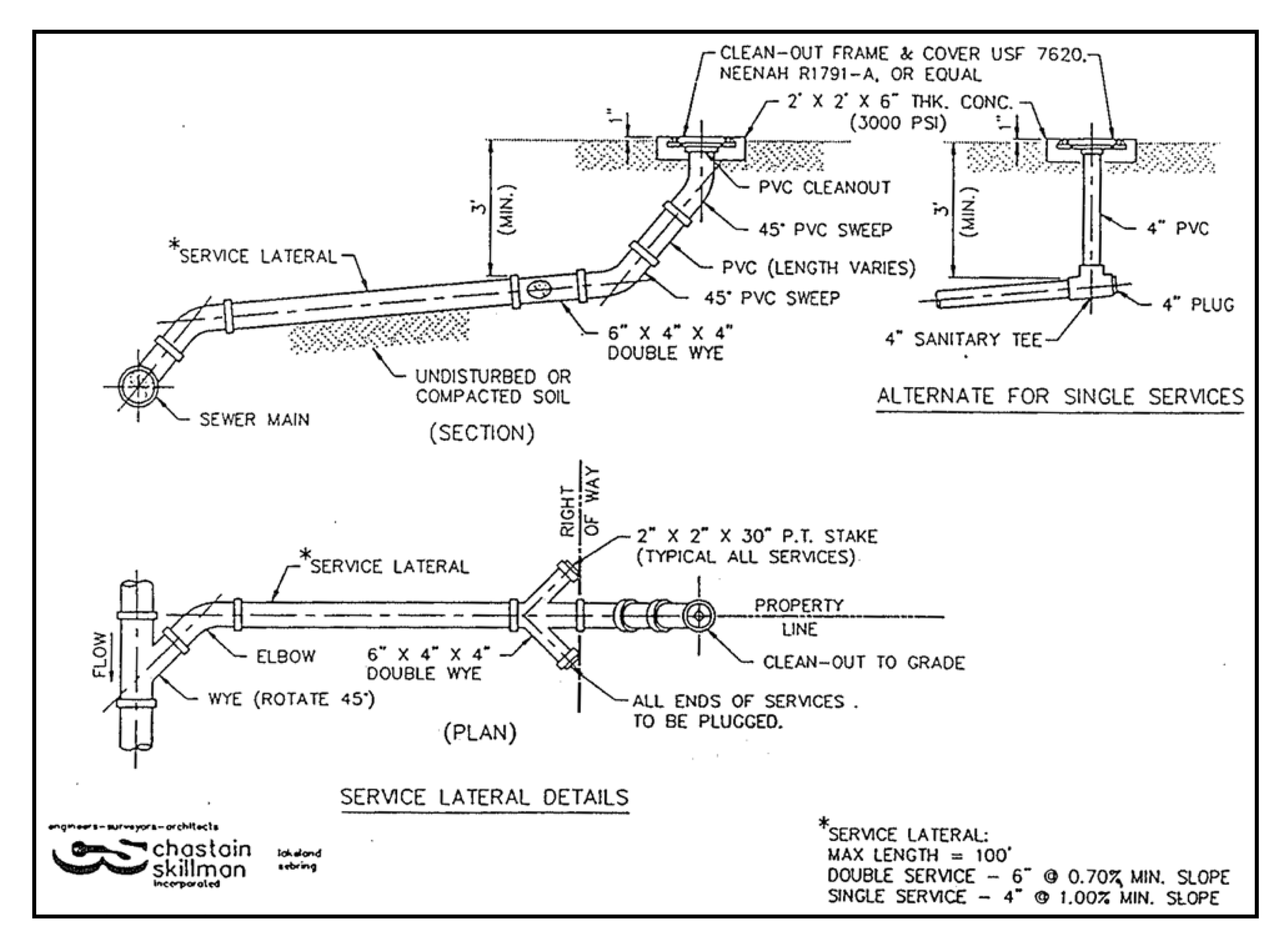
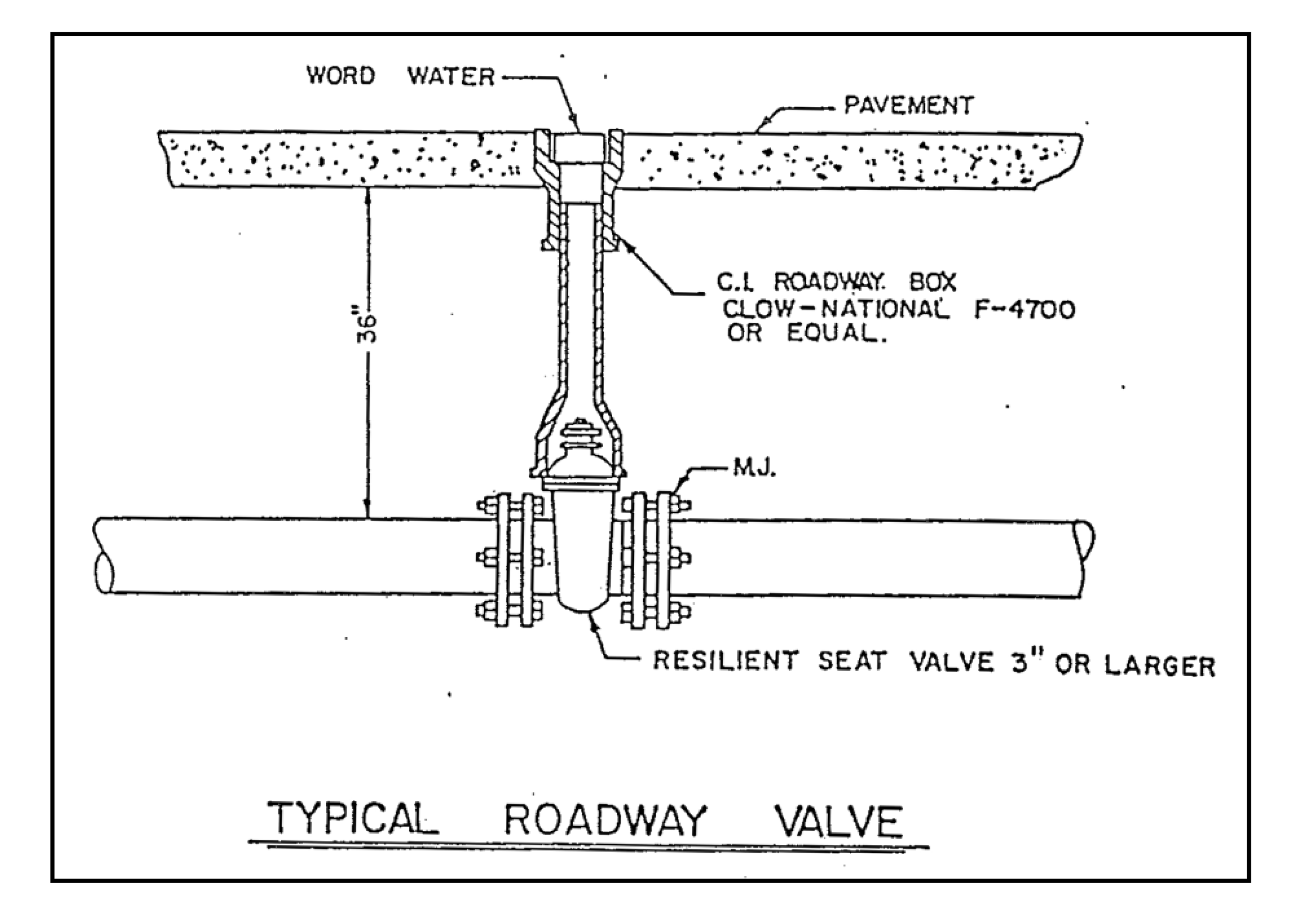
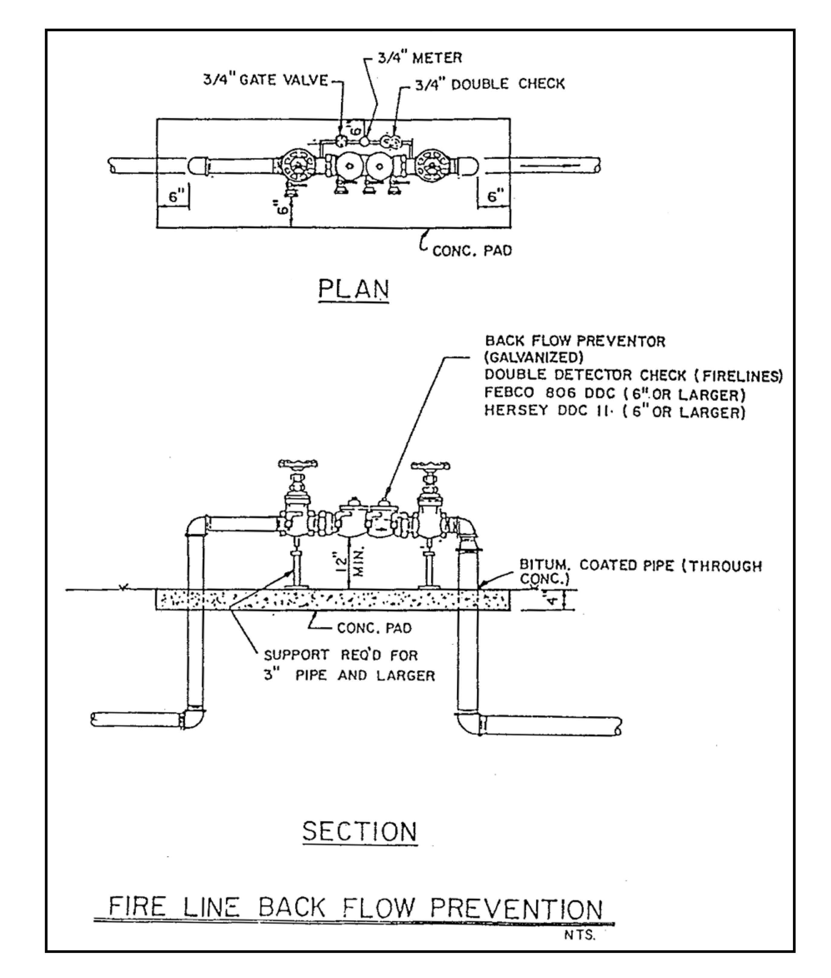
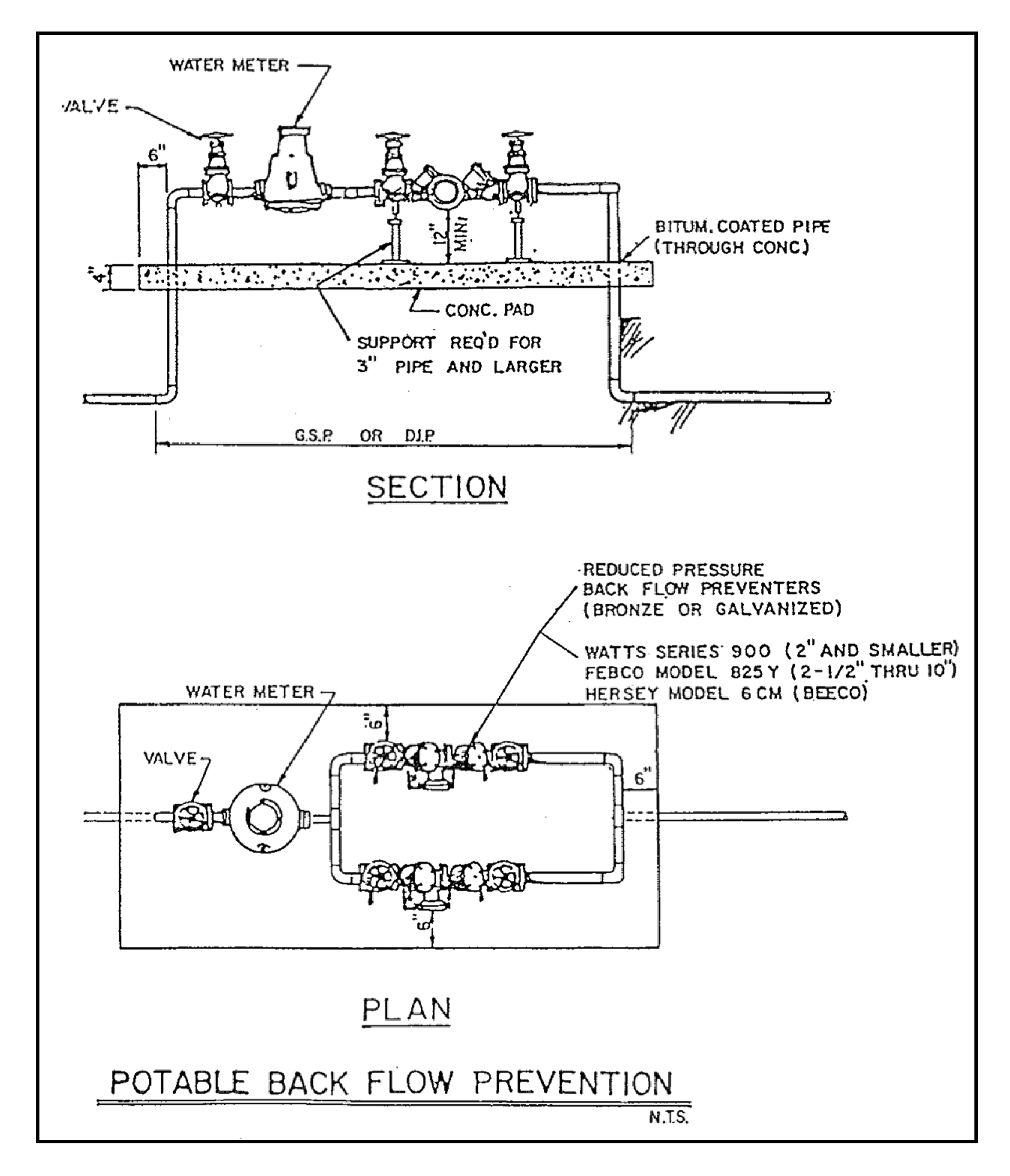
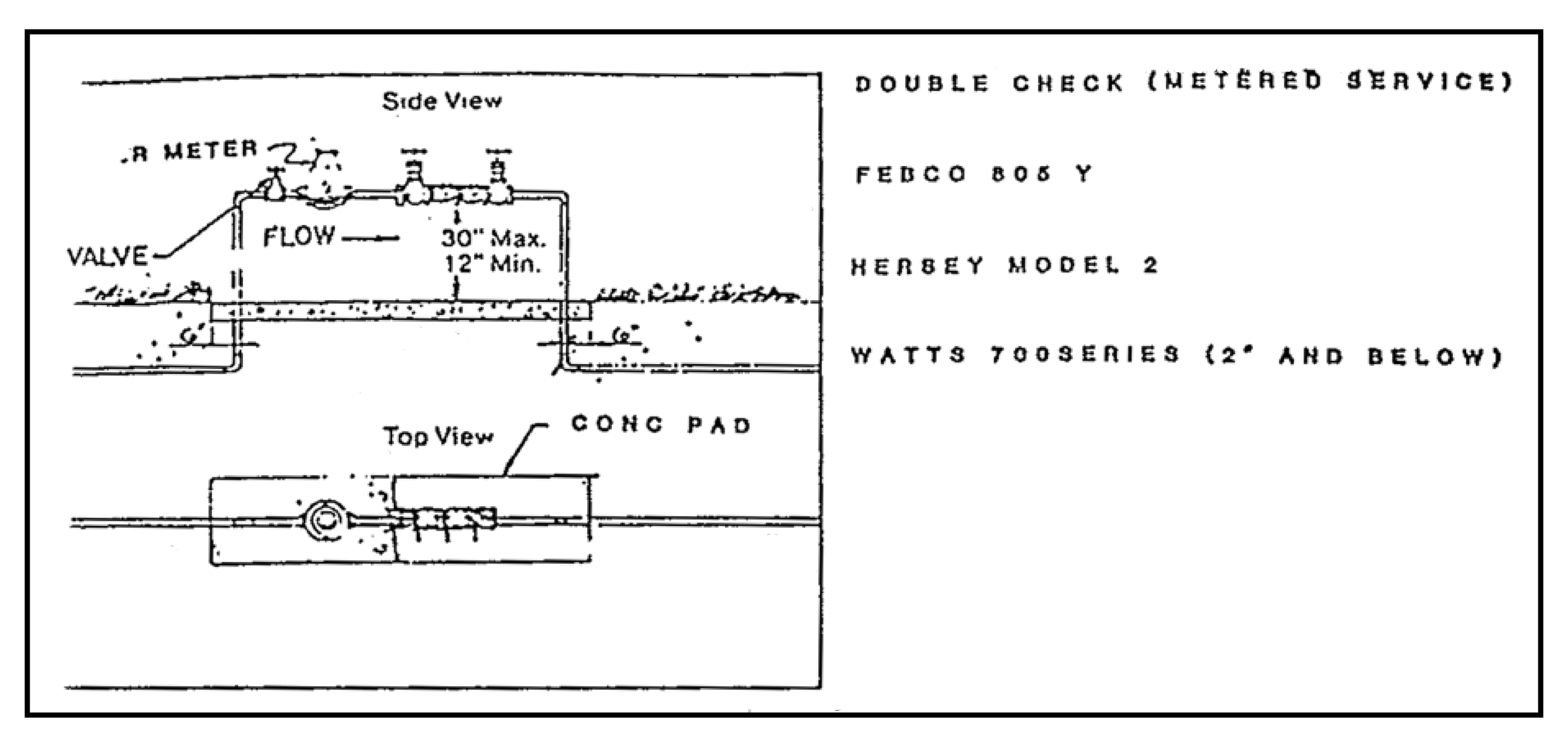
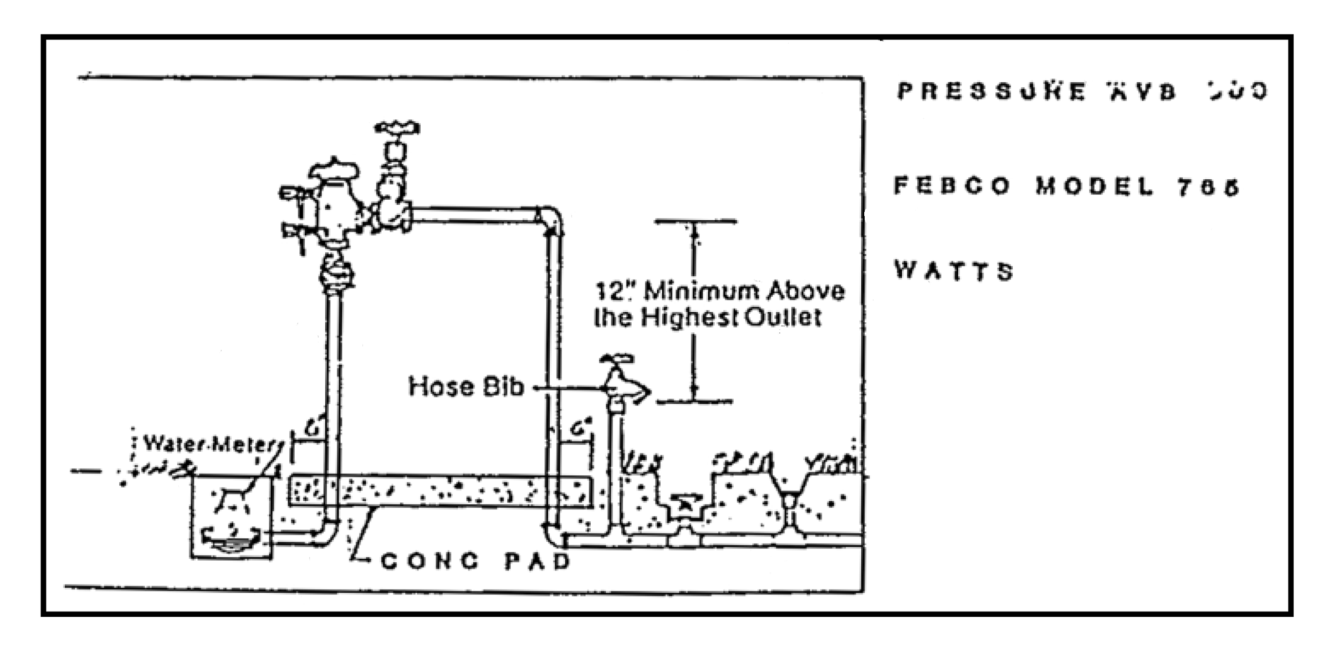
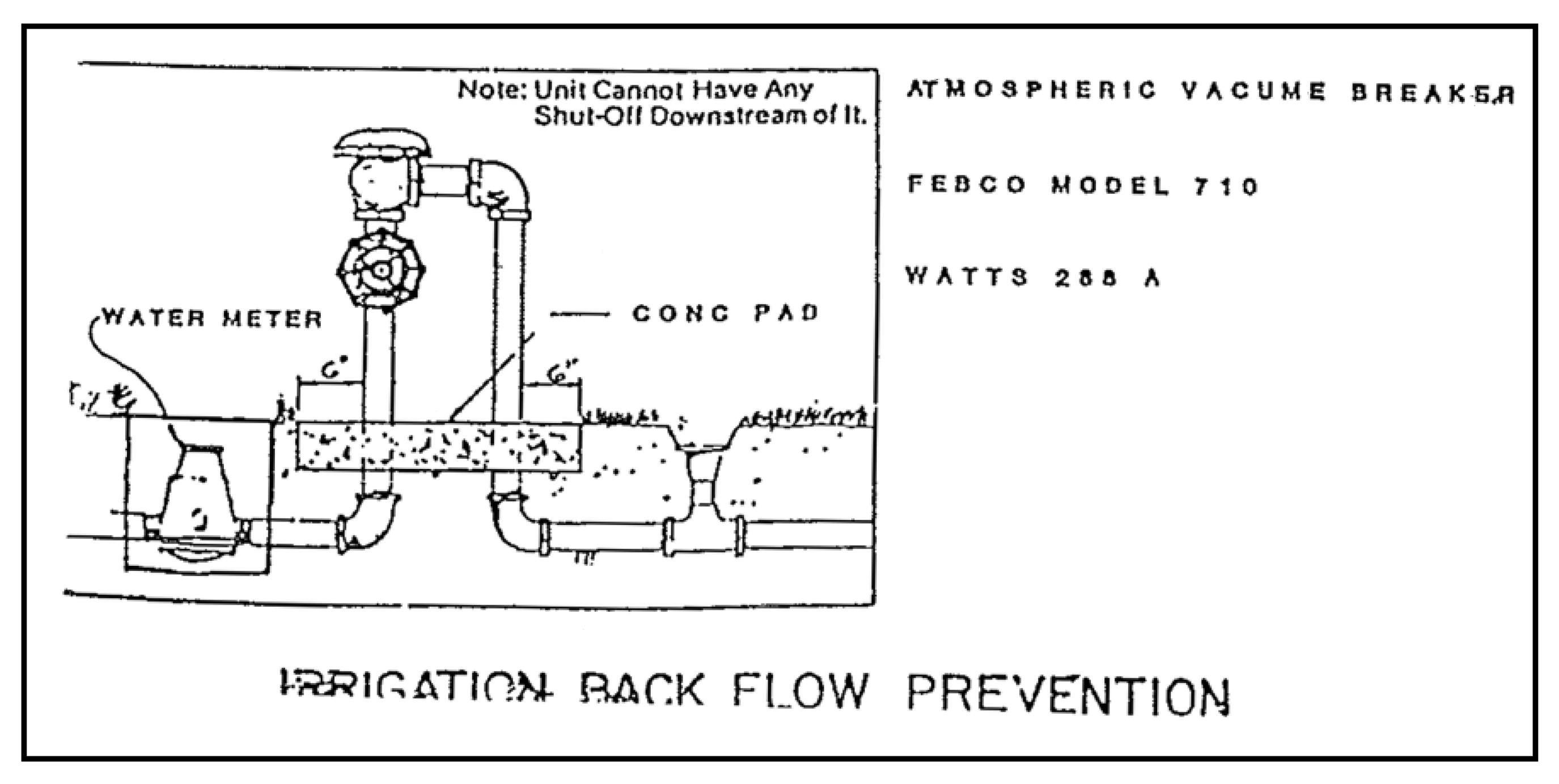
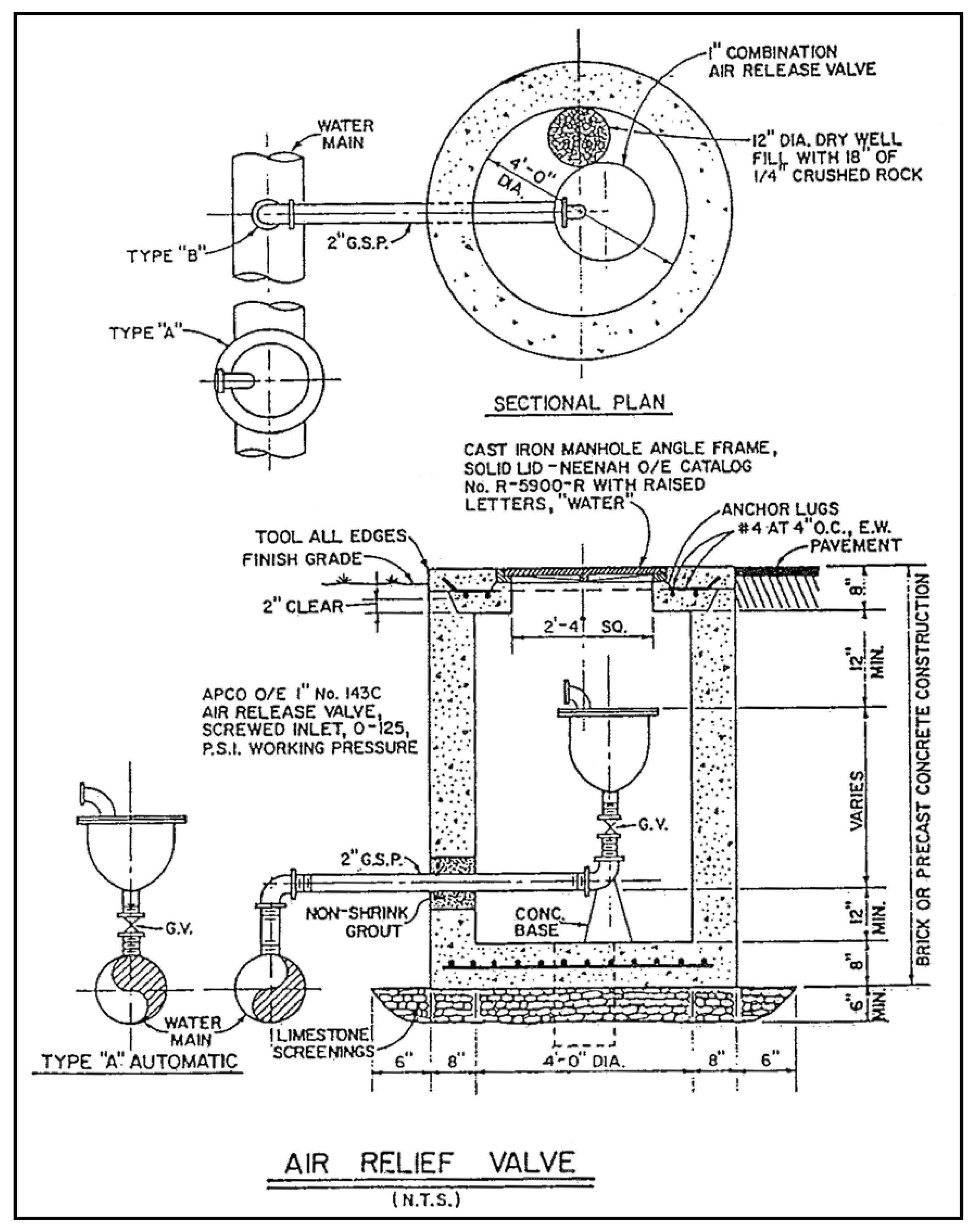
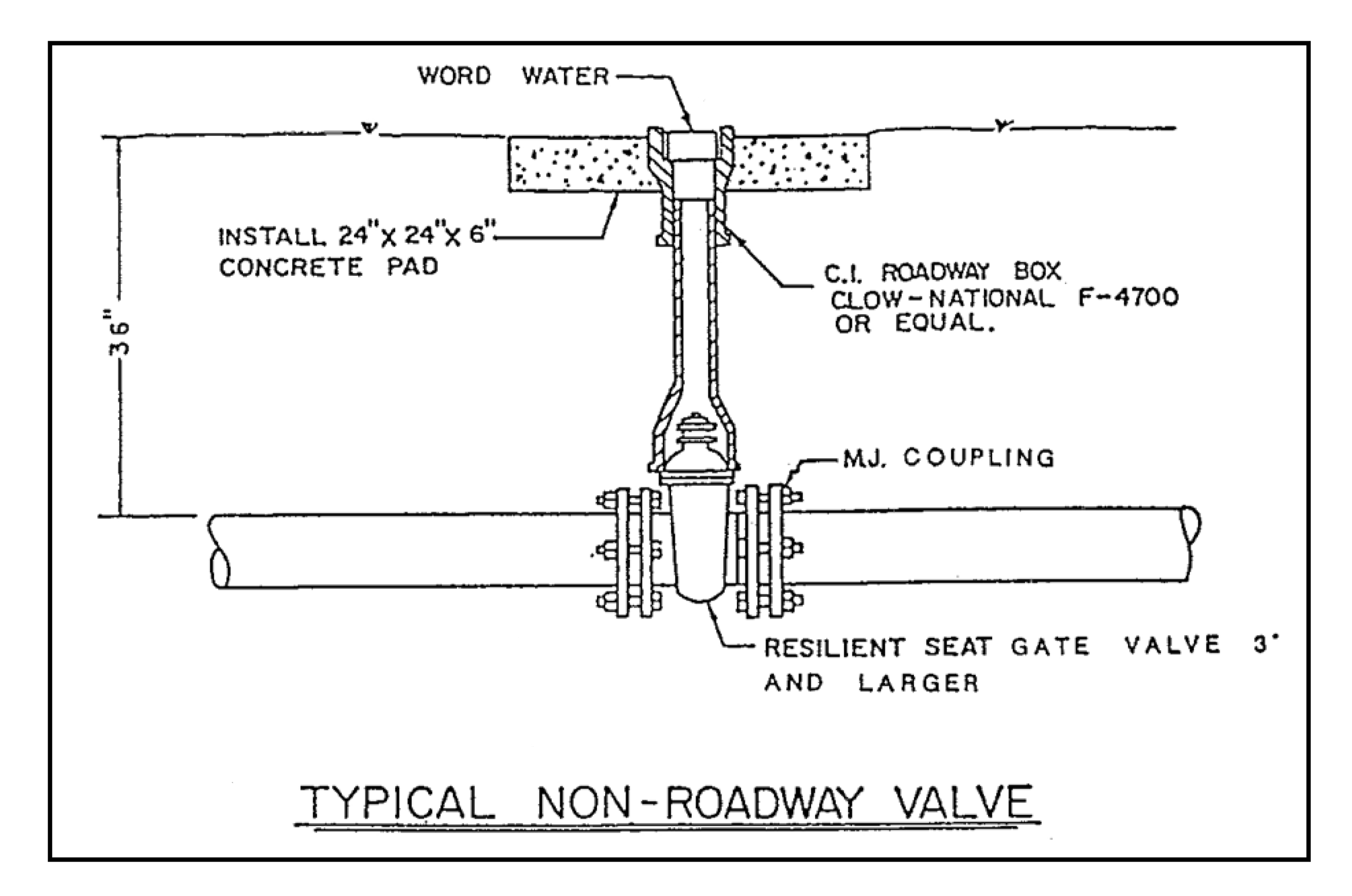
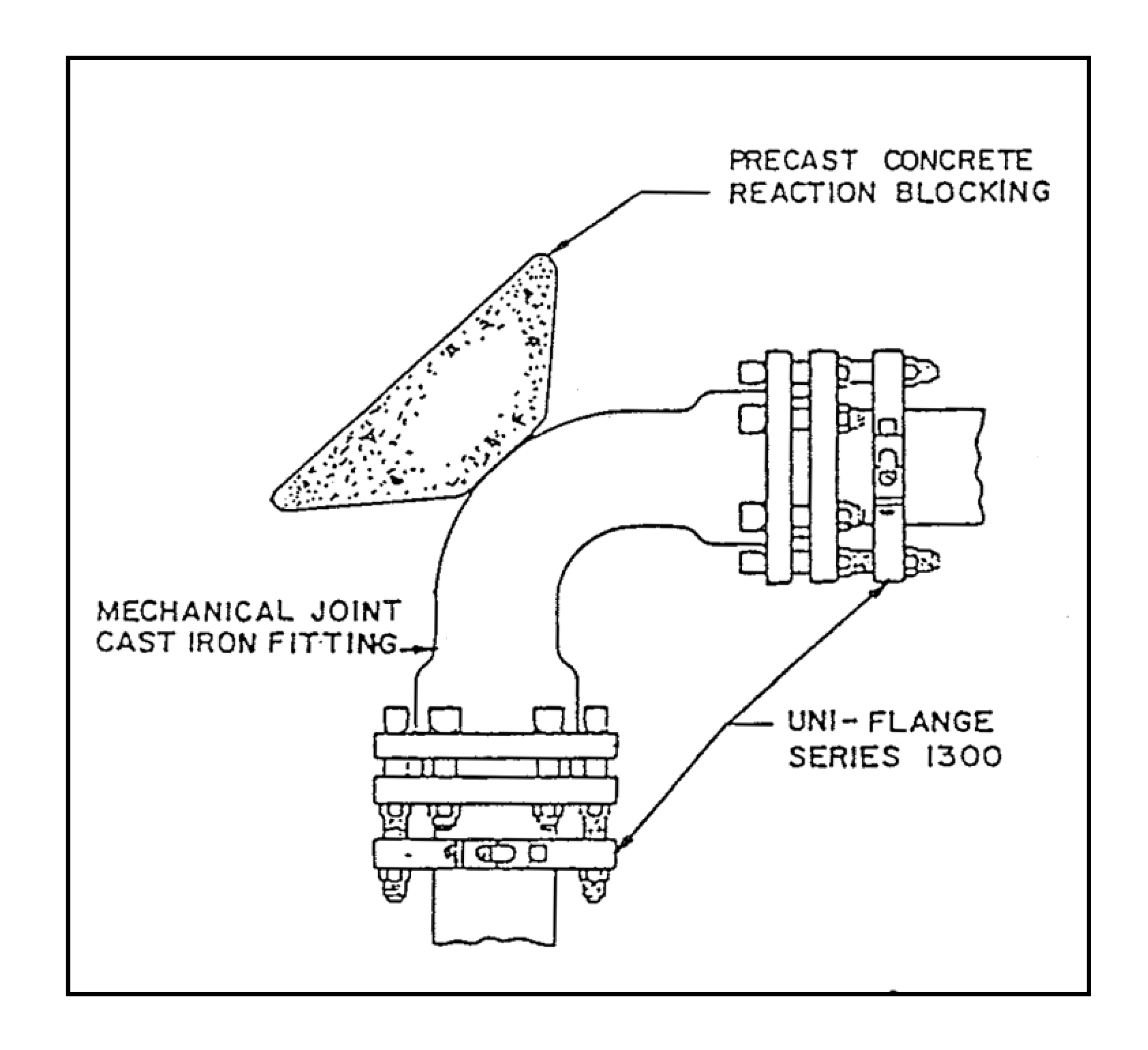
RESTRAINING CLAMPS AND RODS
USE FOR ALL BENDS AND TEES
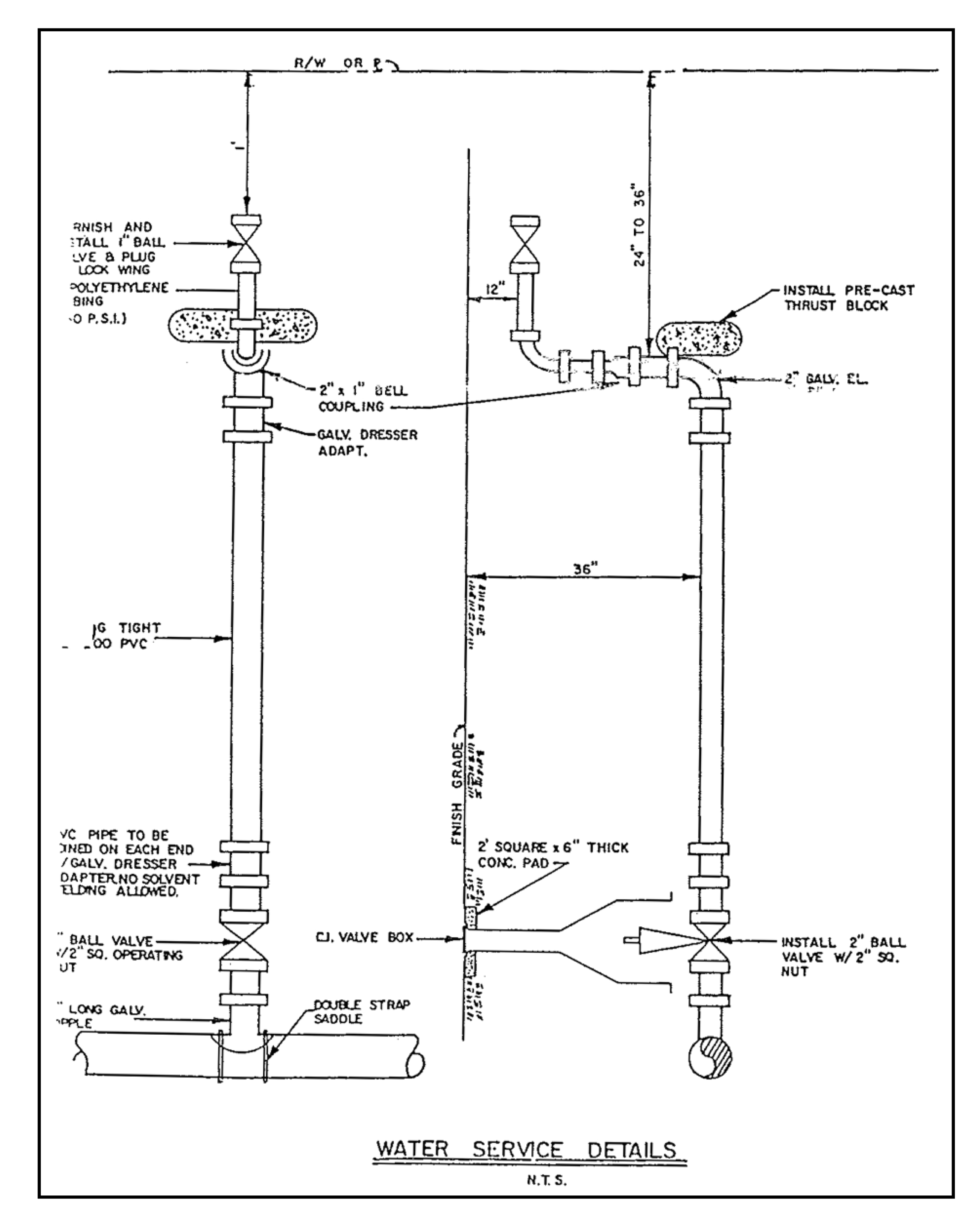
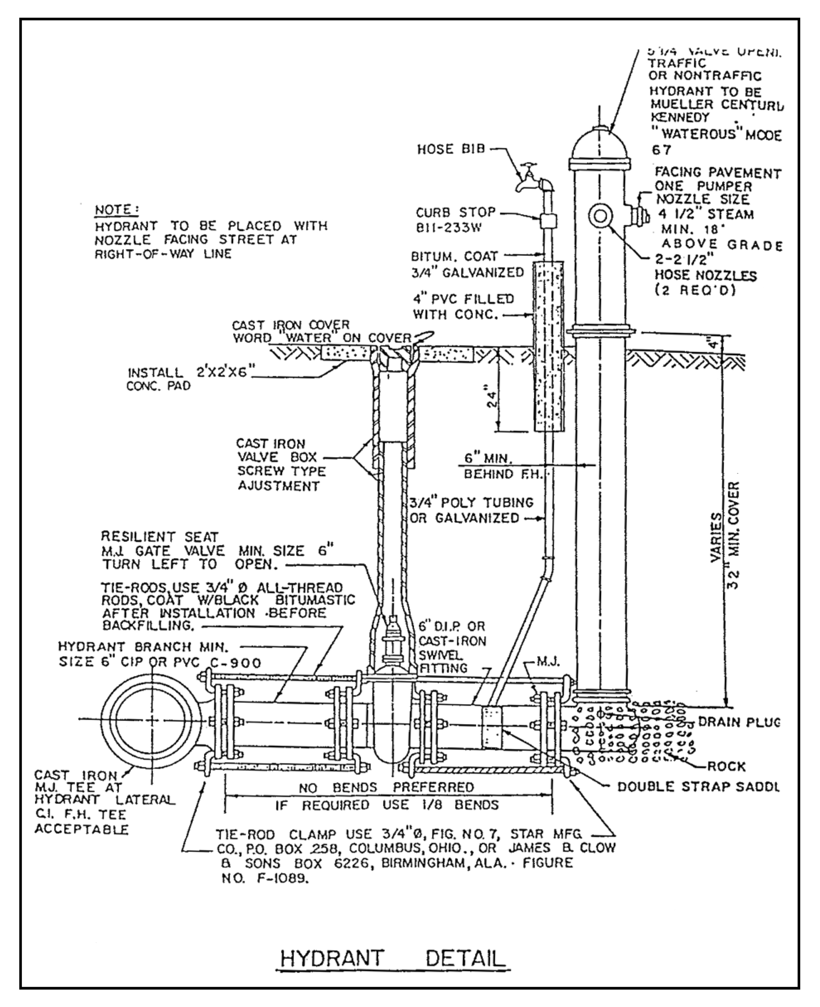
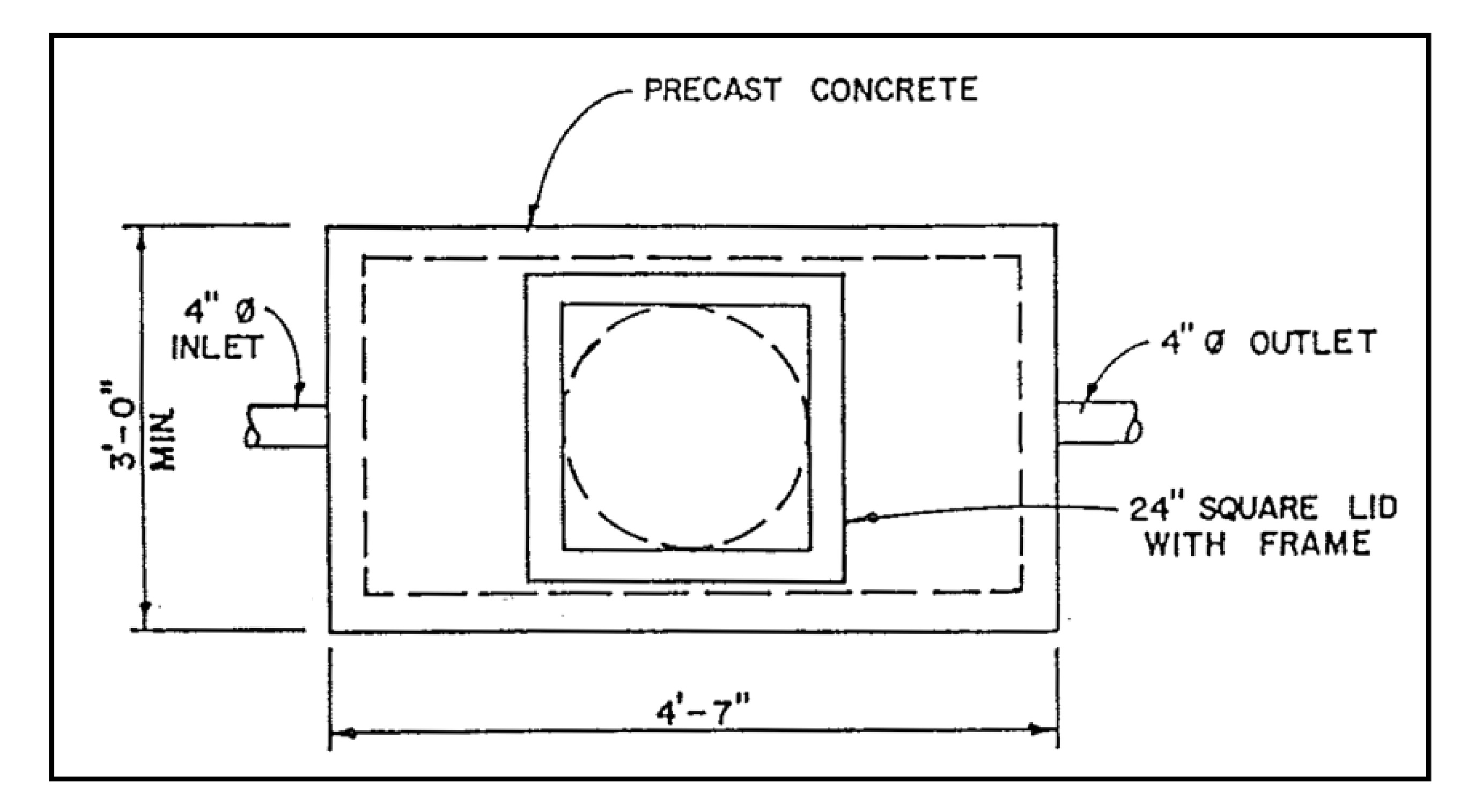
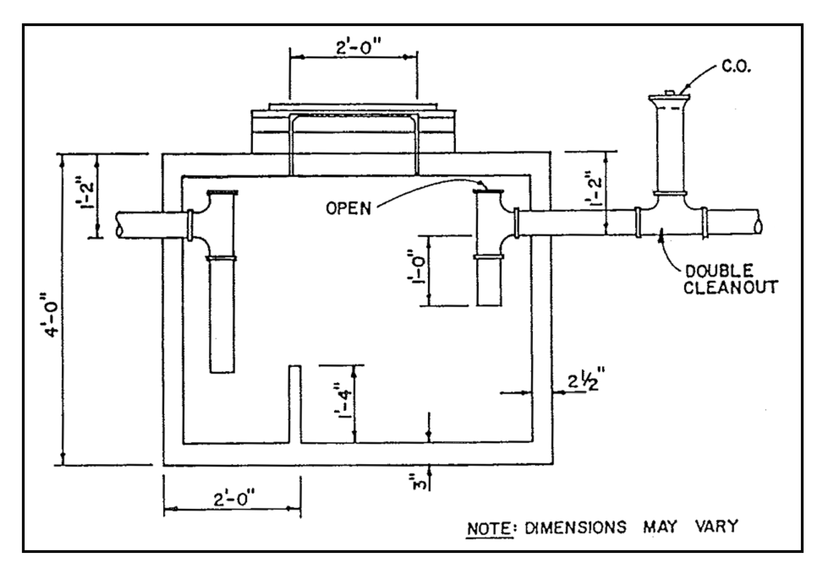
GREASE TRAP DETAIL
Sec. 9.G.1.10. - Purpose and intent.
It is the purpose and intent of the Eagle Lake City Commission to secure the public safety, health, and general welfare of the citizens of Eagle Lake, Florida, by regulating standards of construction for dwellings and providing for the enforcement of violations to this chapter and the other provisions of the land development code throughout the city.
Sec. 9.G.1.20. - Remedial.
This chapter of the land development code is hereby declared to be remedial, and shall be construed to secure the beneficial interest and purposes thereof - which are public safety, health, and general welfare - through structural strength, stability, sanitation, adequate light and ventilation, and safety to life and property from fire and other hazards incidental to the construction, alteration, repair, removal, demolition, use, and occupancy of dwellings, apartment houses, or buildings and structures, or premises used as such.
Sec. 9.G.1.30. - Applicability.
The provisions of this chapter shall apply to all areas of the city to every building or structure used in whole or in part as a dwelling unit or as two or more dwelling units, irrespective of the primary use of such building or structure and irrespective of when such building or structure may have been constructed, altered, or repaired.
Sec. 9.G.1.40. - Minimum provisions and requirements.
This chapter establishes minimum standards for occupancy and does not replace or modify any standards otherwise established for construction, replacement, or repair of buildings except as are contrary to the provisions of this code.
Sec. 9.G.2.10. - General.
No person shall occupy, lease, sub-lease, let, or sub-let to another, for occupancy any building, dwelling, dwelling unit, mobile/manufactured home, structure, or accessory structure, designed or intended to be used for the purpose of living, sleeping, cooking, or eating therein which does not comply with the requirements hereinafter set forth, nor shall any vacant dwelling, building, or structure be permitted to exist which does not comply with the applicable following requirements:
Sec. 9.G.2.20. - Minimum requirements for plumbing, wastewater, and sanitary systems.
1.
Sanitary facilities required. Every dwelling unit shall contain not less than one kitchen sink, one lavatory, one tub or shower, and one water closet, all in good working condition and properly connected to an approved wastewater system.
2.
Location of sanitary facilities. All required plumbing fixtures shall be located within the dwelling unit and be accessible to the occupants of same. The water closet, tub or shower, and lavatory shall be located in a room affording privacy to the user and such room shall have a minimum floor space of 30 square feet; with no dimension less than four feet.
3.
Plumbing fixtures. The plumbing fixtures of every dwelling, dwelling unit, building, or structure shall be maintained in a sanitary condition as prescribed by the plumbing code. Water lines, waste and sewer lines, plumbing stacks, vents, and drains shall be properly installed, connected, and maintained in working order, and shall be capable of performing the function for which they are designed. Water supply inlets to fixtures shall be installed and maintained in such a manner that backflow or cross connection will not be possible.
4.
Hot and cold water supply. Every dwelling unit shall have connected to the kitchen sink, lavatory, and tub or shower and an adequate supply of both cold and hot water. All water shall be supplied through a pipe distribution system connected to a potable water supply.
5.
Water heating facilities. Every dwelling unit shall have water heating facilities which are properly installed and maintained in a safe and good working condition and are capable of heating water to such a temperature as to permit an adequate amount of water to be drawn at every required kitchen sink, lavatory basin, bathtub, or shower at a temperature of not less than 120 degrees Fahrenheit.
6.
Wastewater disposal system. Every septic tank, grease trap, waste and sewer line, or similar installation shall be maintained in a sound condition and shall, at all times, be covered with earth or approved material to prevent deterioration or damage.
Sec. 9.G.2.30. - Minimum requirements for electrical systems.
1.
Electrical lights and outlets. Where there is electric service available to the building structure, every dwelling and dwelling unit shall be wired for electric lights and convenience receptacles. Every habitable room of such dwelling shall contain at least two separate and remote type electric convenience outlets; and in every bathroom and laundry room, there shall be provided at least one convenience outlet. All new bathroom outlets shall have ground-fault circuit interrupter protection. Every kitchen, bathroom, hall, stairway, and bedroom shall contain at least one ceiling or wall type electric light fixture. Any new ceiling electric light fixture shall be controlled by a wall switch. Every such outlet and fixture shall be properly installed, shall be maintained in good and safe working condition, and shall be connected to the source of electric power in a safe manner.
2.
Light in public halls and stairways. Every common hall and inside stairway in every building containing three or more dwelling units shall be adequately lighted at all times. Every public hall and stairway in structures devoted solely to dwelling occupancy and containing not more than four dwelling units may be supplied with conveniently located light switches, controlling an adequate lighting system which may be turned on when needed, instead of full time lighting.
3.
Electrical equipment. All fixtures, receptacles, equipment, and wiring required by this code shall be maintained in a state of good repair, safe, capable of being used, and installed and connected to the source of electric power, in accordance with the electrical code.
4.
Obsolete electrical service. Where the determination is made, upon examination of the existing electrical service supply, that such electrical service is obsolete or is being used in such a manner as would constitute a hazard to life and property, the following shall be used for determining the adequacy of such service: less than ten Kilowatt load and less than six separate circuits requires a minimum of 60-amp service; ten Kilowatt load and six or more separate circuits requires a minimum of 100-amp service.
Sec. 9.G.2.40. - Exterior and interior of structures.
1.
Foundation. The building foundation system shall be maintained in a safe manner and capable of supporting the load which normal use may cause to be placed thereon. The foundation elements shall adequately support the building at all points.
2.
Structural supports. Every structural element of the dwelling shall be maintained in a structurally sound condition and show no evidence of deterioration which would render it incapable of carrying normal loads.
3.
Exterior walls. Every exterior wall shall be free of holes, breaks, loose or rotting boards, or timbers, and any other conditions which might admit rain or dampness to the interior portions of the walls or to the occupied spaces of the building. All siding material shall be kept in good repair.
4.
Roofs. Roofs shall be structurally sound and maintained in a safe manner and have no defects which might admit rain or cause dampness in the walls or interior portion of the building.
5.
Means of egress. Every dwelling unit shall have safe, unobstructed means of egress with minimum ceiling height of seven feet leading to a safe and open space at ground level.
6.
Stairs, porches, and appurtenances. Every inside and outside stair, porch, and any appurtenances thereto shall be safe to use and capable of supporting the load that normal use may cause to be placed thereon and shall be kept in sound condition and good repair.
7.
Protective railings.
A.
At least one hand railing shall be provided for any unenclosed structure over 36 inches from the ground level or on any steps containing four or more risers.
B.
Interior stairs and stairwells more than four risers high shall have handrails located in accordance with the requirements of the building code. Handrails or protective railing shall be capable of bearing normally imposed loads and be maintained in good condition.
8.
Windows and exterior doors.
A.
Every window, window sash, and exterior door shall be properly fitted within its frame, provided with the proper hardware, and shall be substantially weather tight, watertight, and rodent proof, and shall be kept in sound working condition and good repair.
B.
Every window required for light and ventilation for habitable rooms shall be capable of being easily opened and secured in position by window hardware.
C.
Every window sash shall be fully supplied with securely fitting glass window panes or an approved substitute which are without open cracks or holes.
D.
Every exterior door shall be provided with properly installed hardware that is maintained to ensure reasonable ease of operation to open, close, and secure in an open or closed position, as intended by the manufacturer of the door and attached hardware.
E.
Exterior door frames shall be properly maintained and shall be affixed with weather-stripping and thresholds as required to be substantially weather tight, watertight, and rodent and insect restrictive when the door is in a closed position.
F.
Exterior door jambs, stops, headers, and moldings shall be securely attached to the structure, and maintained in good condition without splitting or deterioration that would minimize the strength and security of the door in a closed position.
9.
Screens. Dwellings which do not have a central air conditioning system shall have screens on all exterior openable windows and shall have a screen door with a self-closing device on all exterior doors except for the main entrance door.
10.
Protective treatment. All exterior wood surfaces, other than decay resistant woods, shall be protected from the elements and decay by painting or other protective covering or treatment. All siding shall be weather resistant and water tight. All masonry joints shall be sufficiently tuck pointed to ensure water and air tightness.
11.
Accessory structures. Garage, storage buildings, and other accessory structures shall be maintained and kept in good repair and sound structural condition.
12.
Interior floors, walls, and ceilings.
A.
Every floor, interior wall, and ceiling shall be substantially rodent proof, shall be kept in sound condition and good repair and shall be safe to use and capable of supporting the load which normal use may cause to be placed thereon.
B.
Every toilet, bathroom, and kitchen floor surface shall be constructed and maintained so as to be substantially impervious to water and so as to permit such floor to be easily kept in a clean and sanitary condition.
13.
Interior doors. Every existing interior door shall fit reasonably well within its frame and shall be capable of being opened and closed by being properly and securely attached to jambs, headers, or tracks as intended by the manufacturer of the attachment hardware. Every interior door shall be provided with proper hardware, securely attached and maintained in good condition. Hasp lock assemblies are not permitted on the exterior side of the door of habitable rooms.
Sec. 9.G.2.50. - Heating facilities.
Every dwelling unit shall have heating facilities which are properly installed, are maintained in safe and good working conditions, and are capable of safely and adequately heating all habitable rooms and bathrooms in every dwelling unit located therein to a temperature of at least 68 degrees Fahrenheit, at a distance of three feet above floor level, under ordinary minimum winter conditions. Unvented fuel burning heaters shall be prohibited.
Sec. 9.G.2.60. - Cooking and heating equipment.
All cooking and heating equipment facilities shall be installed in accordance with the building, gas, or electrical code and shall be maintained in a safe and good working condition.
Sec. 9.G.2.70. - Light and ventilation.
Every habitable room shall have at least one window or skylight facing directly to the outdoors. The minimum total window area, measured between stops, for every habitable room shall be eight percent of the floor area of such room. Whenever walls or other portions of structures face a window of any such room and such light-obstruction structures are located less than three feet from the window and extend to a level above that of the ceiling of the room, such a window shall not be deemed to face directly to the outdoors and shall not be included as contributing to the required minimum total window area. Whenever the only window in a room is a skylight type window in the top of such room, the total window area of such skylight shall equal at least 15 percent of the total floor area of such room. Each window or skylight required for minimum light shall be easily opened, and the total of the openable window area in each habitable room shall be equal to at least 45 percent of the minimum window or skylight area size, as required, or shall have other approved, equivalent ventilation. Year round mechanically ventilating air systems may be substituted for windows as required herein, in rooms other than rooms used for sleeping purposes. Window-type air conditioning units are not included in this exception.
Sec. 9.G.2.80. - Bathroom.
Every bathroom shall comply with the light and ventilation requirements for habitable rooms, except that no window or skylight shall be required in adequately ventilated bathrooms and water closet rooms equipped with an approved ventilation system.
Sec. 9.G.2.90. - Minimum dwelling space.
Every dwelling unit or dwelling shall contain at least 150 square feet of floor space for the first occupant and at least 100 additional square feet of floor space area per additional occupant. The floor area shall be calculated on the basis of the total of all habitable rooms. In every dwelling unit of two or more rooms, every room occupied for sleeping purposes there shall be at least 70 square feet for the first two occupants and at least 50 square feet of floor area per additional occupant.
Sec. 9.G.2.100. - Minimum ceiling height.
Every habitable room other than kitchen, storage rooms, and laundry room shall have a ceiling height of not less than seven feet. If any room has a sloping ceiling, at least one-half of the floor area shall have a ceiling height of at least seven feet.
Sec. 9.G.2.110. - Occupancy of dwelling unit below grade.
No basement or cellar space or space below the average finished grade of the main first floor of any building shall be used as a habitable room or dwelling unit unless all the following conditions can be complied with:
1.
The floor and walls are impervious to leakage of underground and surface runoff water and are insulated against dampness, and
2.
The total window area in each room is equal to at least the minimum window area size as required in section 9.G.2.70, and
3.
Such required minimum window area is located entirely above the grade of the ground adjoining such window area, and
4.
The total of openable window area in each room is equal to at least the minimum as required under section 9.G.2.70 except where there is supplied some other device affording adequate ventilation.
Sec. 9.G.2.120. - Sanitation requirements.
1.
All public or shared areas, habitable rooms, or any dwelling or dwelling unit, structure, accessory structure, or building shall be kept in a clean and sanitary condition by the occupant or owner.
2.
All garbage or rubbish shall be disposed of and kept in the manner prescribed in the city solid waste management requirements.
3.
Nothing shall be placed, constructed, or maintained on any premises that shall in any way constitute a nuisance or fire hazard.
4.
All buildings, structures, accessory structures, dwellings, or dwelling units shall be free from infestation.
Sec. 9.G.2.130. - Maintenance.
All buildings or structures, both existing and new, and all parts thereof, shall be maintained in a safe and sanitary condition. All devices or safeguards which are required by this chapter in a building when erected, altered, or repaired, shall be maintained in good working order. The owner, or his designated agent, shall be responsible for the maintenance of buildings, structures, and premises.
Sec. 9.G.2.140. - Mobile/manufactured homes.
These standards shall be used to assure safe and livable housing conditions for mobile and/or manufactured homes. Repair and remodeling of such homes may use material and design equivalent to the original construction.
1.
Electrical repair of mobile/manufactured homes shall be in accordance with this chapter and the electrical code.
2.
The sanitary sewer and water systems serving each mobile/manufactured home shall be in accordance with the Standard Building Code.
3.
Mobile/manufactured homes shall be tied down and blocked in accordance with the minimum requirements of section 320.8325, Florida Statutes, or other applicable general laws of the State of Florida, and rules and regulations promulgated pursuant thereto; and the Standard Building Code.
Sec. 9.G.3.10. - Housing official.
The housing official is hereby designated as the investigating and enforcing authority pursuant to the provisions of this chapter. The housing official is hereby authorized and directed to receive all complaints of a violation of this code, to gather all relevant information concerning said complaints, to conduct field investigation and inspection of real property, and to enter upon real property in the conduct of its official business pursuant to this chapter. The housing official shall also be responsible for providing all notices to affected property owners required by this code and to take such other action as is reasonably necessary to accomplish the purpose of this code.
Sec. 9.G.3.20. - Inspectors.
The housing official, with the approval of the administrative official, may appoint such number of officers, inspectors, assistants, and other employees as shall be authorized from time to time.
Sec. 9.G.3.30. - Restrictions on employees.
No officer or employee connected with the department shall have financial interest in the furnishing of labor, material, or appliances for the construction, alteration, or maintenance of a building within the incorporated limits of the city, or in the making of plans or of specifications thereof, unless he is the owner of such building. No such officer or employee shall engage in any work which is inconsistent with his duties or with the interests of the department.
Sec. 9.G.3.40. - Right of entry.
In accordance with the requirements of applicable federal or state law, the housing official or his agent, upon presentation of proper identification to the owner, agent, or tenant in charge of such property, may enter any building, structure, dwelling, apartment, apartment house, or premises during all reasonable hours to enforce this code, except in cases of emergency where extreme hazards are known to exist which may involve the potential loss of life or severe property damage in which case the above limitations shall not apply.
Sec. 9.G.4.10. - Inspections.
The housing official shall make or cause to be made inspections to determine the condition of residential buildings and premises in the interest of safeguarding the health and safety of the occupants of such buildings and the general public. For the purpose of making such inspections, the housing official, or his agent, is hereby authorized to enter, examine, and survey at all reasonable times all residential buildings and premises. The owner or occupant of every residential building or the person in charge thereof shall give the housing official free access to such residential building and its premises, at all reasonable times for the purpose of such inspection, examination, and survey.
Sec. 9.G.4.20. - Requirements not covered by code.
Any requirements, not specifically covered by this code, found necessary for the safety, health, and general welfare of the occupants of any dwelling, shall be determined by the enforcement officer subject to appeal to the planning commission.
Sec. 9.G.4.30. - Procedure for enforcement.
1.
Unsafe residential buildings. All residential buildings, mobile/manufactured homes, or other structures which are unsafe, unsanitary, unfit for human habitation, or not provided with adequate egress, or which constitute a fire hazard, or are otherwise dangerous to human life, or which in relation to human life or which in relation to the existing use constitute a hazard to safety or health by reason of inadequate maintenance, dilapidation, obsolescence, or abandonment, are considered unsafe buildings. All such unsafe buildings are hereby declared illegal and shall be abated by repair and rehabilitation or by demolition.
2.
Notice of violation. Whenever the housing official determines that there are reasonable grounds to believe that there has been a violation of any provision of this chapter or of any rule or regulation adopted pursuant thereto, he shall give notice of such alleged violation to the owner or responsible person therefor and such alleged violation shall constitute a nuisance. Such notice shall:
A.
Be put in writing prescribing such remedial action deemed necessary by the provision of this code.
B.
Allow 45 days to correct major violations and 60 days to correct minor violations with maximum time limit of 120 days for either, subject to approval of the housing official.
C.
State that, if such repairs, reconstruction, alterations, removal, or demolition are not voluntarily completed within the stated time as set forth in the notice, the housing official shall institute such proceedings for violation and penalties as prescribed by this code.
3.
Service of notice. The written notice required by this chapter shall be deemed to have been served upon the owner if:
A.
A copy thereof is personally delivered to the party to be notified; or
B.
A copy is left at the party's usual place of abode with some person of the family over 18 years of age and informing such person of the contents thereof; or
C.
A copy is mailed by either registered or certified United States mail with return receipt required; or
D.
If the name of such party or his place of residence or his post office address cannot be ascertained after diligent search and inquiry or in the event a notice sent by either registered or certified mail shall be returned undelivered, said notice is posted in a conspicuous place on the property upon which violations are located for 24 hours.
Sec. 9.G.4.40. - Condemnation.
1.
Dangerous structures. Any dwelling or dwelling unit which shall be found to have any of the following defects shall be condemned as unfit for human habitation and declared to be a nuisance and shall be so designated and placarded by the housing official:
A.
One which is so damaged, decayed, dilapidated, unsanitary, unsafe, or vermin-infested that it creates a serious hazard to the health or safety of the occupants or the public.
B.
One which lacks illumination, ventilation, or sanitation facilities adequate to protect the health or safety of the occupants or the public.
2.
Formal notice. Whenever the housing official has declared a dwelling unit as unfit for human habitation and constituting a nuisance, he shall give notice to the owner of such declaration and placard the dwelling unit as unfit for human habitation. Such notice shall:
A.
Be in writing;
B.
Include a description of the real estate sufficient for identification;
C.
State the time occupants must vacate the dwelling unit(s);
D.
State that, if such repairs, reconstruction, alterations, removal, or demolition are not voluntarily completed within the stated time as set forth in the notice, the housing official shall institute proceedings charging the person with a violation of this chapter.
3.
Service of notice. Service of notice to vacate shall be as follows:
A.
A copy thereof is personally delivered to the party to be notified; or
B.
A copy is left at the party's usual place of abode with some person of the family over 18 years of age and informing such person of the contents thereof; or
C.
A copy is mailed by either registered or certified United States mail with return receipt requested; or
D.
If the name of such party or his place of residence or his post office address cannot be ascertained after diligent search and inquiry or in the event a notice sent by either registered or certified mail shall be returned undelivered, said notice is posted in a conspicuous place on the property upon which violations are located for 24 hours;
E.
The housing official or his authorized agent is authorized to condemn and placard any building, dwelling, structure, or accessory structure which in his opinion and observation is in violation of this code and is unsafe, unfit, or unsanitary for human occupation. The housing official, or authorized agent may placard the premises and order the premises be evacuated or closed to occupancy. Any unauthorized person removing, defacing, or mutilating any such notice, order, or placard as provided for in this chapter shall be deemed to be in violation of this code.
4.
Occupancy of building. No dwelling unit which has been condemned and placarded as unfit for human habitation shall again be used for human habitation until approval is secured from and such placard is removed by the housing official. The housing official shall remove such placard whenever the defect or defects upon which the condemnation and placarding action were based have been eliminated.
Sec. 9.G.5.10. - Code enforcement board; special magistrate.
Where applicable to the purpose and scope of this chapter the provisions of the city Code chapter 2, administration; article 2, boards, committees, and commissions; division 2, code enforcement board and as amended by City Ordinance O-07-27, Special Magistrate, are hereby adopted and incorporated into and made a part hereof by reference, and the terms are used interchangeably herein.
Sec. 9.G.6.10. - Permitting.
1.
Any owner, authorized agent, or contractor who desires to construct, enlarge, alter, repair, move, improve, remove, convert, or demolish a residential building or structure or to cause such work to be done, shall first make application to the city and obtain the required permit therefor.
2.
The owner of property who resides on such property may make alterations and repairs to his structure (after obtaining the required permit), if in the judgment of the housing official, the work proposed is not in violation of state statutes and poses no threat to the public safety and welfare.
Sec. 9.G.7.10. - Hardships.
Where the literal application of the requirements of this code would appear to cause undue hardship on an owner or tenant or when it is claimed that the true intent and meaning of this code or any of the regulations therein have been misconstrued or wrongly interpreted, the owner of such building or structure, or his duly authorized agent, may appeal the decision of the housing official to the planning commission as set forth herein.
Sec. 9.G.7.20. - Time extension.
In appropriate cases where the application of the requirement of this code in the allowance of the stated time for the performance of any action required hereunder would appear to cause undue hardship on an owner, the planning commission may permit one extension of time, not to exceed 120 days, from the date of such decision of the planning commission. Applications for additional extensions of time shall be heard by the planning commission. Such request for additional extensions of time shall be filed with the housing official not less than 30 days prior to the expiration of the current stated time.
Sec. 9.G.7.30. - Decision rendition.
All decisions of the planning commission pertaining to hardship appeals will be rendered in writing. The chairman of the planning commission will execute the decision, which will be circulated to the applicant, the city commission, the city manager, the city attorney, and any person requesting same at the public hearing.
Sec. 9.G.8.10. - Violations and penalties.
Any person, firm, corporation, or agent who shall violate a provision of this code, or fail to comply therewith, or with any of the requirements thereof, or who shall erect, construct, alter, repair, move, improve, convert, or demolish a residential building or structure in violation of this chapter, such violation may be presented by the housing official to the code enforcement board. In no event shall a term of imprisonment be imposed for any violation of this chapter.
Sec. 9.G.9.10. - Provisions.
The provisions of this chapter are severable, and if any provision or part thereof shall be held invalid or unconstitutional or inapplicable to any person or circumstances, such invalidity, unconstitutionality, or inapplicability shall not affect or impair the remaining provisions of this chapter.