
Bryan County Unincorporated
City Zoning Code
City Zoning Code
Appendices
Appendix A: - Table of Amendments to UDO Text[2]
Editor's note— As of May 18, 2022, this table will not be updated. Please see the Supplement History Table and Code Comparative Table for a disposition of ordinances amending the UDO.
Appendix B: - Table of Amendments to Zoning Map[3]
Editor's note— As of May 18, 2022, this table will not be updated. Copies of Zoning Map Amendments are available at the city clerk's office.
Appendix C: - Reserved.[4]
Editor's note—Ord. No. 15-2021, adopted July 13, 2021, repealed Appendix C, which derived from Ord. No. 06-2020, § 3, adopted Dec. 8, 2020.
Appendix D: - Development Application Requirements.
Appendix D-1
ZONING SUBMITTAL REQUIREMENTS
APPENDIX D-2
SITE DEVELOPMENT AND SUBDIVISION SUBMITTAL REQUIREMENTS
Appendix D-3\LANDSCAPE PLAN REQUIREMENTS
The landscape plan includes the location, botanical name, common name, quantity and size of all proposed plantings (trees and shrubs) and shall be prepared by a landscape architect licensed in the State of Georgia to prepare planting plans. Additionally, the plan shall include:
a.
Name, address, phone number, and email address of the property owner;
b.
Name, address, phone number, email address, and seal of the firm/persons who are responsible for the plan preparation;
c.
Zoning classification and land use of the property and all adjacent properties;
d.
Location and dimensions of all proposed/existing structures, property lines, servitudes, parking lots and drives, roadways and rights-of-way, sidewalks, signs, refuse and disposal areas, parking facilities, fences, electrical equipment, recreational facilities, drainage facilities, and other freestanding structures;
e.
All existing and proposed impervious surfaces;
f.
Landscape islands;
g.
Buffers, including walls and berms. Height of walls and berms shall be noted and material of the walls shall be identified;
h.
All existing and proposed green infrastructure, if applicable;
i.
Irrigation or watering system plans if applicable. If no irrigation or water system is proposed, show closest water source;
j.
Summary tabulation of all planting requirements, including buffers and tree canopy coverage;
k.
Installation and maintenance details;
l.
Tree protection and preservation plan, which shall include:
1.
Tree Survey, including location, quantity, size (dbh), name (botanical and common), and condition of all existing trees over six inches DBH, including those in the public right-of-way. The plan shall designate which trees are to be retained and which are to be removed;
2.
Delineation of wetlands;
3.
Identify waters of the state
4.
Tree protection details for trees to be retained (if landscape plan is submitted separately, tree protection details shall be included on landscape plan as well);
5.
Inventory of Protected Trees, including identifying Protected Trees to be removed;
6.
Mitigation calculations for Protected Trees to be removed;
7.
Canopy coverage analysis based on the following calculations:
CR=SA x 0.4
Where:
CR = canopy area requirement
SA = site area
PROCEDURE FOR CALCULATING THE REQUIRED TREE REPLACEMENT:
Step 1: Area of total site from boundary survey.
Step 2: Multiply area (in square feet) by 0.4.
Step 3: Subtract preserved tree area (as determined by the Tree Survey) from Step 2.
Step 4: Select enough overstory and understory trees to equal area remaining after Step 3.
Example calculation:
Step 1: 10-acre site = 435,600 sq. ft.
Step 2: 40 percent canopy cover figure: 435,600 X 0.4 = 174,240 sq. ft. to meet 40 percent canopy cover.
Step 3: Preserved trees left on-site = 108,900 sq. ft. (2.5 acres)
174,240 minus 108,900 = 65,340 sq. ft. of replacement trees.
Step 4: Replacement trees required to meet 40 percent canopy coverage: 65,340 sq. ft. of area to be planted in trees.
40 overstory (large canopy trees) x 1500 sq. ft. = 60,000 sq. ft.
9 overstory (medium canopy trees) x 550 sq. ft. = 4,950 sq. ft.
2 understory (small canopy tress) x 250 sq. ft. 500 sq. ft.
Total square footage of trees planted 65,450 sq. ft.
Note: The additional trees to meet minimum canopy coverage do not need to be shown on the tree protection and preservation plan. They may be shown on the landscape plan.
8.
Stamped and signed by an arborist
m.
Any additional information required by the Community Development Department.
Appendix D-4
RECORD DRAWING REQUIREMENTS
Record Drawings shall comply with the most current GIS standards and shall include all control points using the state plan coordinates and monuments. Record Drawings shall include the following information:
1.
General Information
a.
Project or subdivision name
b.
Scale & north arrow
c.
Legend or clearly labeled symbols
d.
Horizontal & vertical datum
e.
Clear location map
f.
Developer's name, address and phone number
g.
Name & address of registered professional
h.
Statements of Engineer, Contractor, Surveyor and JWSC
i.
Plans clearly show delineation between private infrastructure & public infrastructure
2.
Drainage
a.
Manhole invert, inlets, pipe inverts, frames, headwall, and end treatments elevations (MSL).
b.
Length, grade, diameter, pipe material between structures, manholes, inlets and end treatments.
c.
Locations of structures, headwall, manholes, inlets, and end treatments in relation to right-of-way lines, property lines, and other permanent structures.
d.
Locations of line, slope, width, and depth of ditches, swales, canals, and drainage basins.
3.
Pavement
a.
Edge of pavement when it differs more than two feet from approved construction drawings.
b.
Pavement profiles when grade of installed paving differs more than 0.1 percent from proposed grades.
c.
Areas where conditions require alternative bases or subgrade material or treatment.
4.
Water
a.
Location of water mains, length b/w valves, bends, and tees, depth, grade and diameters.
b.
Locations of valves, blow-offs, fire hydrant, and service leads/meters locations in relation to property lines, road intersections and other permanent structures.
c.
Locations of all service laterals. Measurements shall be from permanent structures and shall indicate the location of the connection at the main and the location at the property line with depth to the end of the service lateral at the property line.
d.
Reference table of state plane coordinates of isolation valves, fire hydrants, water service ends (not applicable for Private Systems)
e.
Distance from adjacent property corners, curb lines or other fixed point
f.
Delineated water easements to be dedicated (15 feet water in center unless otherwise approved)
g.
Northing and Easting coordinates for all water appurtenances as well as underground fittings.
5.
Sanitary Sewer
a.
Manhole invert elevations (MSL), invert elevations of all mains at the manhole and elevations of all manhole tops.
b.
Lateral locations measured from the downstream manhole at the main, and at the property line if the lateral is not perpendicular to the main.
c.
Length, grades, size and type of material between manholes.
d.
Locations of manholes in relation to the right-of-way lines, property lines, and other permanent structures.
e.
Northing and Easting coordinates for all sewer appurtenances as well as underground fittings.
6.
Gravity Collection & Force Mains
a.
Rim Elevation & inverts of all pipes entering/leaving manholes
b.
Location of manholes, service clean-out/stub-out, isolation and air release valves, sewer mains, force mains & service lines clearly labeled
c.
Reference table provided State Plane Coordinates of manholes, isolation, and air release valves (not applicable for private systems)
d.
Pipe diameter, length, material and grades on gravity sewer lines
e.
Show storm drain crossings & length of ductile iron or concrete encased pipe as applicable
f.
Service lateral stationing, depth of service pipe at marker, distance behind marked curb & distance to one adjacent property corner
g.
Tax assessors' parcel identification number & platted subdivision lot number or E-911 address
h.
Delineated sanitary sewer easements to be dedicated (20' w/sewer in center unless otherwise approved)
7.
Sewer Lift Stations and Force Mains
a.
Actual Elevations of wet well influent line inverts, bottom of wet well at lowest point, top of slab over wet well, & top of discharge line leaving wet well going to valve pit vault
b.
Location, diameter, length and pipe type of force mains
c.
Lift Station property lines w/ access road if applicable
8.
Other
a.
Locations of all special construction requirements in addition to the above such as
i.
Sheeting left in place;
ii.
Concrete cradles;
iii.
Concrete encasement; end of casings; and
iv.
Section of casing and carrier pipe depicting the material and installation requirements if different from the approved construction plans.
Appendix D-5
CONSTRUCTION INSPECTION STANDARDS
Construction Inspections shall adhere to the following standards:
1.
Proof-rolling of the sub-grade base shall be performed in the presence of a representative of the Engineering Department. Any unsatisfactory areas shall be corrected to the satisfaction of the engineering director prior to proceeding with the installation of the rock base course or construction of curb. Sub-grade laboratory compaction testing may be required by the County if adequate compaction cannot be satisfactorily determined by proof-rolling.
2.
Proof-rolling of the roadway rock base shall be performed in the presence of a representative of the Engineering Department. Any unsatisfactory areas shall be corrected to the satisfaction of the engineering director or duly authorized representative prior to proceeding with the installation of the asphalt courses.
3.
Prior to backfill of any cross-drain pipe, the installation shall be inspected by the Engineering Department.
4.
Pavement mix design reports prepared by an independent laboratory shall be submitted for approval prior to paving.
5.
Laboratory compaction, stability and density testing is required for pavement. Compressive strength testing is required for concrete curb and gutter. Pavement core sample reports are required at 500-foot spacing to show thickness of bases and surface. Reports shall include a map showing core locations.
6.
All test results must be submitted to the Engineering Department prior to proceeding with the next sequence of construction. Specifically, compaction results must be submitted and approved prior to:
a.
placement of curb and gutter;
b.
all sub-grade test results prior to placement of base material; and
c.
base thickness and compaction results prior to asphalt surface pour.
7.
If any of the above tests show substandard conditions, then additional tests may be required by the engineering director to reveal the extent and cause of the substandard condition. All tests shall be performed by a qualified independent testing laboratory approved by the engineering director.
8.
A proposed plan to correct substandard conditions shall be submitted by the applicant's engineer for approval by the engineering director prior to beginning work.
Criteria for Requiring Replacement of Curb and Gutter
1.
Improper contraction joints.
2.
"Y" cracks.
3.
Spalling cracks.
4.
Off-grade or misaligned sections.
5.
Any crack within two feet of an expansion or construction joint (remove half, with saw cut joint).
6.
Two or more cracks of any size within ten feet.
7.
Failure to meet strength or location specifications.
8.
If any crack exceeds 1/8" in width.
Appendix E: - Road Classification Plan.
Detailed maps available from the engineering director
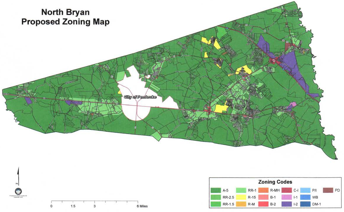
(Ord. No. 01-2021, 1-12-2021)
Detailed maps available from the engineering director
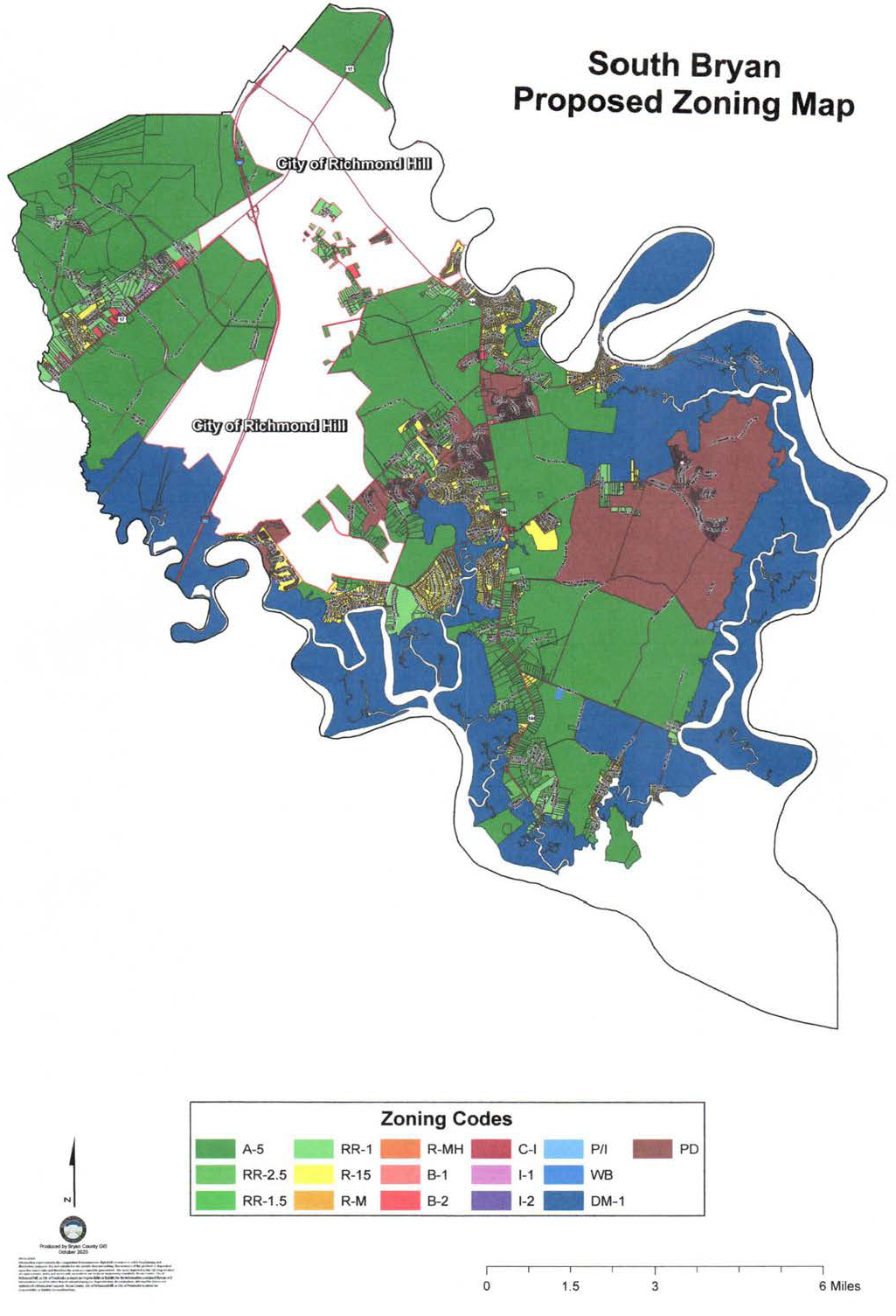
(Ord. No. 01-2021, 1-12-2021)
Appendix F: - Consolidated Table Of Authorized Land Uses.
(Ord. No. 06-2020, § 3, 12-8-2020; Ord. No. 16-2021, § 2, 8-10-2021)