Carbon County Unincorporated
City Zoning Code
City Zoning Code
12 Engineering
Design And Construction Standards
12.1.0 Intent
This section defines the general requirements for improvements to be built by the developer, sub-divider, owner or contractor for all types of construction, (to include residential, commercial, industrial and professional office). The improvements shall include all street improvements in front of all lots and along all dedicated streets to a connection with existing improvements of the same kind or to the boundary of the subdivision nearest existing improvements. Layout must provide for future extension to adjacent development and to be compatible with the contour of the ground for proper drainage. All water lines, sewer lines, and any other buried conduit shall be installed to the boundary lines of the subdivision or development
HISTORY:
Ord. 539, 6/17/2020
Ord. 545, 3/17/2021
12.2.1 Concept Plan
Requirements for the concept plan shall conform to the current Carbon County Development Code 6.3.2.
The developer shall then prepare a concept plan and shall submit (2) copies of the same to the Zoning Administrator, along with payment of zoning fees, not less than fourteen (14) days prior to the next regularly scheduled Planning Commission meeting. Said plan shall be prepared in accordance with County standards.
Where a developer owns or controls more land than he proposes to submit for preliminary approval, the Planning Commission may require that a concept plan for the larger area be submitted. Said plan shall indicate the portion proposed to be submitted initially for preliminary approval and the portion to be held for future submission.
Said plan shall contain at a scale of not less than one inch equals fifty (50) feet:
- Property boundary
- Adjacent property owners
- Natural water courses
- Location(s) of all existing utilities
- Proposed lots and their approximate dimensions
- Proposed surface drainage
- Other information required by staff or other public agencies
The Zoning Administrator may require that the concept plan be prepared by a Utah Licensed Professional Land Surveyor, (P.L.S.).
HISTORY:
Ord. 539, 6/17/2020
Ord. 545, 3/17/2021
12.2.2 Preliminary Plat
Requirements for the preliminary plan shall conform to the current Carbon County Development Code 6.3.5.
Upon approval of the concept plan by the Planning Commission, the developer shall submit not less than two (2) copies of a preliminary plan of the subdivision prepared by a Utah licensed P.L.S. along with payment of zoning fees, to the Zoning Administrator not less than fourteen (14) days prior to the next regularly scheduled Planning Commission meeting.
Said plan shall contain:
- The name of the proposed subdivision.
- The location of the subdivision as part of a larger tract where the plan submitted covers only part of the developer's tract.
- The surveyor's name and license number.
- The owners of all land immediately adjoining the land to be subdivided.
- A contour map at five (5) foot intervals when required by the Zoning Administrator or Planning Commission.
- Identification of elevations and/or flood plains as defined by FEMA and include the map number.
- The boundary lines of the tract and all existing or platted streets, roads, streams, waterways, utility lines, existing buildings, and other important features.
- The location, width, and other dimensions of proposed roads, streets, easements, parks, common drives, privately owned access ways, open space, trails, common facilities, and other improvements and dedications.
- A drainage plan of all areas of the proposed development including vacant or open space, proposed building sites, existing or proposed ditches, canals, curbs, storm drains, retention ponds, and other drainage facilities; the County Engineer will review the drainage plan for approval.
- North point, scale, date of drawing.
- Engineering calculations, drawings, typical cross sections, plans, schematics, or written statements regarding the plans. Engineer calculations and drawings shall include, but are not limited to:
- Plans and profiles showing the finished grade at street locations and typical cross-section of street pavements including curbs and gutters, sidewalks, drainage easements, rights-of-way, irrigation ditches, manholes, and catch basins; the locations of street signs; the location, size and invert elevations of existing and proposed sanitary sewers, storm water drains, and fire hydrants, showing connection to any existing or proposed utility systems; and exact location, elevation, depth, and size of all water, gas, or other underground utilities or structures.
- Location, size, elevation, and other appropriate descriptions of any existing facilities or utilities, including, but not limited to, existing streets, sewers, drains, water mains, easements, water bodies, streams, and other pertinent features such as swamps, railroads, buildings, at the point of connection to proposed facilities and utilities within the subdivision, and shall identify any utility and drainage conflicts.
- The proposed location of all utility improvements to be installed by the developer, such as water lines, sewer lines, gas lines, electrical power lines, communication lines, storm drains, secondary water, etc.
All plan documents and other data shall be prepared in accordance with County standards. Failure to submit all required material prepared in accordance with said standards shall be grounds for denial.
HISTORY:
Ord. 539, 6/17/2020
Ord. 545, 3/17/2021
12.2.3 Final Plat
Requirements for the final plan shall conform to the current Carbon County Development Code 6.3.7.
Upon approval of the preliminary plan by the Planning Commission, the developer shall prepare the final plat, engineering drawings and documents and shall submit at least two (2) copies of the same, along with payment of zoning fees, to the Zoning Administrator no less than fourteen (14) days prior to the next regularly scheduled Planning Commission meeting.
Said plats, drawings, and documents shall include:
- The original Mylar and one (1) print of the final plat.
- Engineering drawings.
- Documents indicating compliance with the water and sewage disposal requirements for each lot.
- An itemized estimate of the cost of constructing all required improvements, prepared by the developer or his agent, or contractor, who has been approved by the County Engineer. This estimate shall be used as the basis for settling the amount of the performance guarantee.
- A title report, covering the property within the final plat area, to identify all interests in the property which may have an effect on the title, and to establish that the land proposed for subdivision is free of boundary conflicts. The purpose of this requirement shall be to ensure that purchasers of plots will have a clear and marketable title.
- Evidence of a satisfactory storm drainage plan.
- Final copies of all other required documentation, when applicable.
- Evidence of payment of final zoning, recording, and any other fees.
The required copies of the final plans, plats, and documents shall be prepared in accordance with County standards, (see Section 5). Failure to submit the final material in accordance with said standards shall be grounds for denial of further action by the County.
HISTORY:
Ord. 539, 6/17/2020
Ord. 545, 3/17/2021
12.3.0 Utility Connection
It shall be the responsibility of the developer to connect to any utilities or improvements wherever they are located and extend those improvements to and through the development as shown on the approved construction drawings.
HISTORY:
Ord. 539, 6/17/2020
Ord. 545, 3/17/2021
12.4.0 Storm Drainage
The developer shall provide on-site facilities for a 25-year 1-hour storm event and piping and appurtenances to convey the highest intensity 25-year 1-hour storm to the on-site retention facilities. Additional piping and appurtenances shall be required to convey the 25-year historical discharge from the on-site retention facility to a storm water facility. The minimum storm drain pipe size shall be 18 inches.
HISTORY:
Ord. 539, 6/17/2020
Ord. 545, 3/17/2021
12.5.0 Streets, Cul-De-Sacs, Common Drives
Alleys- Alleys shall have a minimum width of twenty (20) feet. Alleys may be required at the rear of business lots, but will not be accepted in residential blocks except under unusual conditions where such alleys are considered necessary by the Planning Commission.
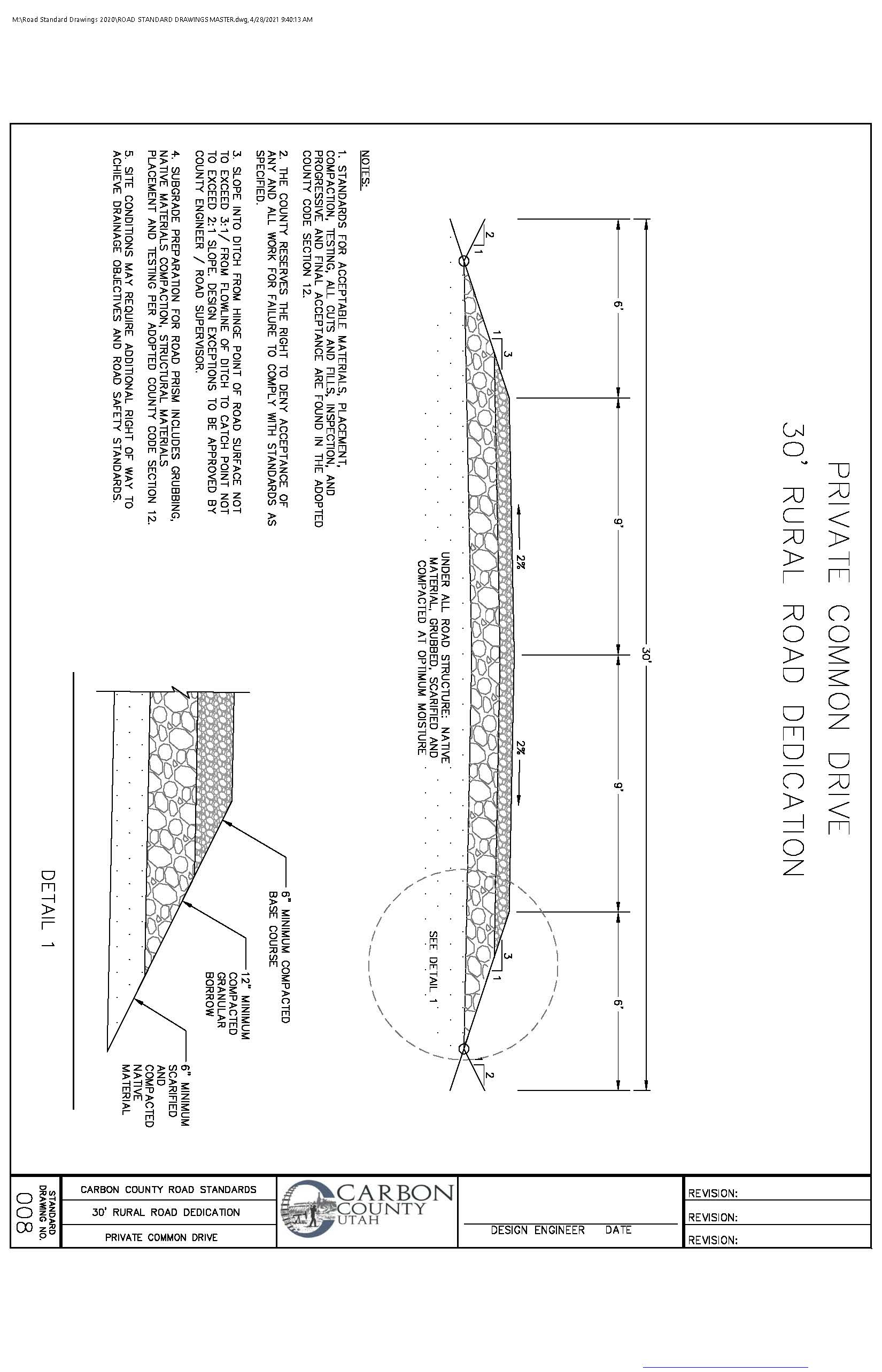
Common/Private Drives- Common or private drives shall be permitted in all residential zones for lots that do not abut on a designated County road or public way when all of the following conditions can be met:
- That the lot is connected to a public road over a common or private drive which is not less than 24 feet in width nor more than two thousand six hundred and forty (2,640) feet in length from the point of connection to the public road.
- The total number of dwelling units utilizing the easement for access shall be not greater than three (3).
- That the common or private drive provides perpetual access to all parcels served by recorded surface easement or fee title ownership.
- That the travelway and drainage shall be constructed in accordance with County standards for common or private drives.
- That a legal document acceptable to Carbon County shall be executed declaring the drive a private roadway and absolving the County from any responsibility for maintenance or construction upon the easement.
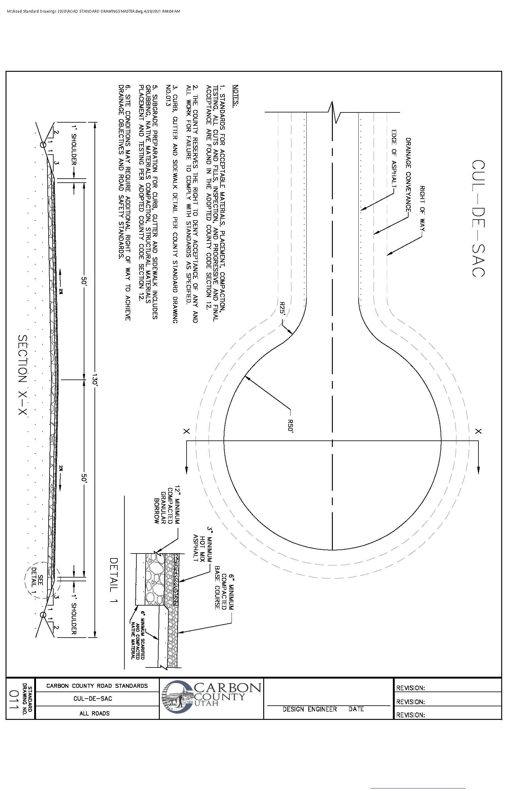
Cul-de-sac- Cul-de-sacs shall be approved only where conditions exist which make other designs undesirable. Each cul-de-sac shall have a turnaround of not less than one hundred (100) feet in diameter. Surface water must drain away from the turnaround, except where surface water cannot be drained away from the turnaround along the street due to grade, catch basins, drainage structures, drainage easements shall be recorded and designated on the subdivision plat.
Divided Lots- Where the land covered by a subdivision included two or more parcels in separate ownership and the lot arrangement is such that a property ownership line divides one or more lots, the land in each lot so divided shall be transferred by deed to single ownership before approval of the final plat, and such transfer recorded in the County Recorder's Office before being certified to the Planning Commission by the subdivider.
Easements- Where alleys are not provided, utility easements of not less than seven (7) feet on each side lot and ten (l 0) feet on each rear lot lines shall be recorded and designated on the subdivision plat. Easements of greater width may be required along property lines where necessary for surface overflow or for the extension of main sewers or similar utilities.
Relation to Adjoining Street Systems- The arrangement of streets in new subdivisions shall make provision for the continuation of the existing streets in adjoining areas (or their proper projection where adjoining land is not subdivided) at the same or greater width (but in no case less than the required minimum width) unless variations are deemed necessary by the Planning Commission.
Reverse Curves- Reverse curves shall have a tangent of at least one hundred (100) feet, unless in the opinion of the County Engineer and Road Department such is not necessary.
Street Curves- Where the street lines within a block deflect from each other at any one point more than ten (10) degrees, there should be a connecting curve. Toe radius of the curve for the inner street line should be not less than 350 feet for a major collector, 250 feet for a minor collector, and 100 feet for local roads.
Street Dedication- All County accepted streets shall be dedicated for public use. The dedication of half streets in any subdivision is prohibited, except on the borders.
Street Grades- The maximum grade shall be 7 percent for collector streets and 10 percent for local streets. Where the observance of this standard is unfeasible, with a recommendation from the County Engineer and the Road and Planning Departments, the Planning Commission shall have the power to grant an exception when special pavement surfaces and adequate leveling areas are installed and in the opinion of the Planning Commission the best subdivision of the land is thereby secured.
Street Intersection- Streets shall intersect each other as nearly as possible at right angles. Minor streets shall approach the major or collector streets at an angle of not less than eighty (80) degrees. Offsets in street alignment of more than ten (10) feet or less than one hundred twenty (120) feet shall be prohibited.
Street Names- New street names should not duplicate those already existing. A street that is obviously a continuation of another already in existence, should bear the same name. Before the street is named, the proposed name must be submitted to and approved by Carbon County GIS and Road Departments.
Street Width- The minimum right-of-way widths of proposed public streets in subdivisions, unless a greater width is required or deemed necessary by the Planning Commission after recommendation for the County Engineering and Road Department, shall be as follows:
- Rural arterials: 84 to 100 feet. See standard drawing 007
- Urban and Rural Major collectors: 66 feet. See standard drawing 005 and 006
- Urban and Rural Minor collectors: 60 feet. See standard drawing 003 and 004
- Urban and Rural Local streets: 50 feet. See standard drawing 001 and 002
HISTORY:
Ord. 539, 6/17/2020
Ord. 545, 3/17/2021
12.6.0 Blocks
Length- The maximum length of blocks, generally, shall be thirteen hundred (1,300) feet and the minimum length of blocks shall be five hundred (500) feet. In blocks over eight hundred (800) feet in length, the subdivider may be required to dedicate a walkway through the block at approximately the center of the block. Such walkway shall not be less than ten (10) feet in width.
Use- Blocks intended for business or industrial use shall be designated especially for such purposes with adequate space set aside for off-street parking and delivery facilities.
Width- The width of blocks generally shall be sufficient to allow two (2) tiers of lots.
HISTORY:
Ord. 539, 6/17/2020
Ord. 545, 3/17/2021
12.7.0 Lots
Angle of Lots- Side lines of lots shall be approximately at right angles, or radial to the street line, except where topographic conditions make it advisable to have side lot lines deflect at sharper angles.
Building Sites- The lot arrangement, design, and shape shall be such that lots will provide satisfactory and desirable sites for buildings and be properly related to topography and confom1 to the requirements set forth herein. Lots shall not contain peculiarly shaped elongations solely to provide necessary square footage which would be unusable for normal purposes.
Corner Lots- Comer lots shall have extra width sufficient for maintenance of required building lines on both streets.
Lot Sizes- All lots shown on the subdivision plat must conform to the minimum requirements of the Zoning Ordinance for the zone in which the subdivision is located.
Lots Must Abut On Public Street- Each lot shall abut on a street dedicated by the subdivision plat or an existing publicly dedicated street, or on a street which has become public by right of use and is at least fifty (50) feet wide, except when approved by the Planning Commission as a mountain home or planned unit development. Interior lots having frontage on two streets shall be prohibited, except where topographic conditions make such design desirable.
Parts of Lots- All remnants of lots below minimum size left over after subdividing of a larger tract must be attached to adjacent lots rather than allowed to remain as unusable parcels.
HISTORY:
Ord. 539, 6/17/2020
Ord. 545, 3/17/2021
12.8.1
The Pre-Construction meeting shall be held to review the project requirements with the Developer and its Contractors. The meeting will be held at the Carbon County offices and shall include, at the Director of Planning's discretion:
- County Engineer, Director of Planning and Road Supervisor;
- Developer;
- Developer's design engineer or construction manager;
- All contractors and sub-contractors involved with installing the development improvements;
- Representatives of the affected utility companies.
HISTORY:
Ord. 539, 6/17/2020
Ord. 545, 3/17/2021
12.9.1
All construction work involving the installation of improvements in subdivisions shall be subject to inspection by a qualified third party testing agency at the cost of the developer. The developer shall be responsible to ensure inspection and certified reports are obtained and maintained on record and are provided in the as-built subdivision packet as required in Carbon County Development Code section 6.11.5. The records shall include the following inspections:
- Compaction of all trenches;
- Proof rolls on native subbase and base (three proof rolls);
- Red heading is required on native, subbase and base; and
- Compaction test on all subbase, untreated base course, and bituminous surface course.
HISTORY:
Ord. 539, 6/17/2020
Ord. 545, 3/17/2021
12.9.2
Certain types of construction shall have continuous inspection while others may have only periodic inspections. It is the responsibility of the developer/subdivider to ensure that all contractors give the county appropriate notice of all construction work set forth in section 12.9.3 below to allow scheduling of said inspections.
HISTORY:
Ord. 539, 6/17/2020
Ord. 545, 3/17/2021
12.9.3
Inspection shall be required on the following types of work:
- Laying of street surfacing;
- Placing of concrete for curbs and gutters, sidewalks and other structures;
- Laying of sewer pipe, drainage pipe, water pipe, lateral connections, pressurized irrigation, valves, hydrants and testing;
- Subgrade;
- Street grading and gravel base;
- Excavations for curbs and gutters and sidewalks:
- Trenches for laying pipe. Inspections shall occur in one (1) foot lifts, and not to exceed fifty (50) feet in length. Trenches less than fifty (50) feet in length shall not have fewer than three tests per each vertical foot of compacted fill.
- Forms for curbs and gutters, sidewalks and structures. No work shall be started except in the presence of, or with the prior approval of, the county engineer or his designee.
- Collars around storm drain inlet boxes/manholes. Thrust blocks for water, collars for storm drain and collars for manhole. Value boxes in asphalt.
- Collars around sewer manholes and water valve boxes.
- Inspectors must be notified and must approve all catch basin elevations and locations prior to final tie-ins.
- Inspectors may require survey stakes with elevations to ensure depths and slopes meet the approved construction drawings. Specifically, requirements may be made on fire hydrants, cleanouts, and sewer manholes.
HISTORY:
Ord. 539, 6/17/2020
Ord. 545, 3/17/2021
12.10.0 Acceptance Of Improvements
Inspection made by the county to determine compliance with the specifications does not imply acceptance of the work. The county requires completion of all facilities before any are finally accepted to start the warranty period established by this code or otherwise by development agreement. Final acceptance of improvements will be made at an inspection by the county at the completion of all improvements. All improvements shall be free from defects or damage at the time of inspection. Specifically, the following are required:
- All asphalt, sidewalks and curbs and gutters shall be free of joints greater than one-eighth inch vertically and horizontally and construction damage and shall be true to line and grade.
- All sewer manholes and water valve boxes shall be raised to pavement level.
- All water valves and hydrants shall be operative.
- All storm drainage improvements shall be completed.
- All debris leaving a job site shall be the responsibility of the contractor to clean up.
- All comers on the subdivision and all lot comers in the subdivision shall be permanently marked.
- A final walkthrough to inspect the improvements shall be arranged by the developer with the county when said improvements are completed. The improvements will be accepted when the punch list from the final walkthrough is completed and accepted by the county.
- All work within the County's Right of Way will require lien waivers.
HISTORY:
Ord. 539, 6/17/2020
Ord. 545, 3/17/2021
12.11.0 Request For Inspection
Requests for inspection shall be made to the county by the person responsible for the construction. Requests for inspection on work requiring inspection shall be made three working days prior to the commencing of the work. The county shall provide written confirmation e-mail for all scheduled inspection appointments.
HISTORY:
Ord. 539, 6/17/2020
Ord. 545, 3/17/2021
12.12.0 Trenching Excavation And Backfill
This section covers the requirements for trenching and backfilling for underground utilities. Unless otherwise shown or ordered, utilities shall be laid in an open trench. All incidental clearing, preliminary grading, structure removal, and benching shall be considered a part of the trenching operation.
HISTORY:
Ord. 539, 6/17/2020
Ord. 545, 3/17/2021
12.12.1 Barricades
Barriers shall be placed at each end of all excavations, and at such places as may be necessary along excavations, to warn all pedestrians and vehicular traffic of such excavations and to prevent persons from walking into, falling into, or otherwise entering those excavations.
HISTORY:
Ord. 539, 6/17/2020
Ord. 545, 3/17/2021
12.12.2 Control Of Groundwater
All trenches shall be kept free from water during excavation, fine grading, pipe laying and jointing, and pipe embedment operations. Where the trench bottom is mucky or otherwise unstable because of the presence of groundwater, and in all cases where the static groundwater is above the bottom of any trench or bell hole excavation, such groundwater shall be lowered to the extent necessary to keep the trench free from water and the trench bottom stable when the work within the trench is in progress. The discharge from excavation dewatering shall be conducted to natural drainage channels, gutters, drains, or storm sewers. The discharge from excavation dewatering shall be filtered through straw bales or other median, to remove silts and debris prior to entering natural drainage channels, gutters, drains, or storm sewers. No sanitary sewer shall be used for disposal of trench water. Surface water shall be prevented from entering trenches.
HISTORY:
Ord. 539, 6/17/2020
Ord. 545, 3/17/2021
12.12.3 Trench Excavation
Excavation for pipelines shall be located as shown on the drawings or as staked in the field. Trenches shall be excavated to the depths and widths required to accommodate the construction of the pipelines, as follows:
- Normal Excavation: Except in ledge-rock, cobbles, stones, or water-saturated earth, mechanical excavation of trenches shall not extend below the bottom of the pipe after placement in its final position.
- Authorized Over-Excavation: Where ledge-rock, cobble rock, stones or other material render the trench material unsuitable for pipe bedding, as determined by accepting utility agency, bedding material shall be imported and placed. The trench shall be excavated to a minimum of four inches (4") below the bottom of the pipe after placement in its final position.
- Where unstable material is encountered in the excavation, foundation material may be required, as determined by the County Engineer. In such cases, a minimum of eight inches (8") below the bottom of the pipe after placement in its final position shall be removed. Over-excavation not ordered, specified, or shown shall be considered to be unauthorized excavation.
- Unauthorized Over-Excavation: Any excavation carried below the elevation required to install the pipe as specified in these specifications, or directed by the County Engineer, shall be considered to be unauthorized. Such excavation shall be backfilled in accordance with these specifications, all at the Developer/Contractor's expense.
HISTORY:
Ord. 539, 6/17/2020
Ord. 545, 3/17/2021
12.12.4 Trench Width
- The trench shall be excavated such that the pipe is always centered in the trench. The minimum clear trench width at the horizontal diameter of the pipe must not be less than the outside diameter of the pipe plus twelve inches (12") on each side. The maximum clear width of trench at the top of the pipe must not be more than the outside diameter of the pipe plus twenty four inches (24"). If a trench is excavated to a greater width, the Developer/Contractor will be required to restore the trench to an acceptable condition by following the steps outlined in these Specifications for trenches in embankments.
- Trench width for pipeline structures, valves, or other accessories shall be sufficient to leave at least twelve inches (12") clear between their outer surfaces and the trench. Backfill with earth under structures or valves will not be permitted. Any unauthorized excess excavation below the elevation indicated for foundation of any structures shall be backfilled in accordance with these specifications at the Developer/Contractor's expense.
HISTORY:
Ord. 539, 6/17/2020
Ord. 545, 3/17/2021
12.12.5 Trenches In Embankments
Before laying pipes that are to be in fill or embankment areas, the embankment shall first be placed and compacted to the specified density to a depth of not less than two feet (2') above the top of the proposed pipe. After placing and compacting the embankment, the trench for the pipe or conduit shall be excavated through the fill and fine graded and the pipe installed as specified.
HISTORY:
Ord. 539, 6/17/2020
Ord. 545, 3/17/2021
12.12.5.1 Placement Of Excavated Material
- All excess material shall be hauled away from the construction site and disposed of in an area obtained by the Developer/Contractor and approved by the County Engineer. The Developer/Contractor shall be responsible for all rights-of-way, easements, and access associated with the disposal of excess excavated material. It shall farther be responsible to obtain permission from the property owner or person controlling the property where the Developer/Contractor plans to dispose of excavated material. No compensation will be made to the Developer/Contractor for disposal of excess excavated material.
- Non-excess excavated material shall be piled in a manner that will not endanger the work and will avoid obstructing sidewalks and driveways. Gutters and irrigation ditches shall be kept clear or other satisfactory provisions shall be made for street drainage and continuity of irrigation.
- Grading of the area surrounding the trenches, including excavated materials, shall be performed as necessary to prevent surface water from flowing into trenches, or other excavations.
HISTORY:
Ord. 539, 6/17/2020
Ord. 545, 3/17/2021
12.12.6 Fine Grading The Trench Bottom
The bottom of the trench shall be accurately graded and prepared to provide uniform bearing and support on undisturbed soil or compacted granular bedding at every point along the entire length of the pipe. Bell holes shall be hand excavated after the trench bottom has been fine graded. Bell holes shall be only large enough to permit making the joints and to assure that any portion of the joint or bell does not support the pipe.
HISTORY:
Ord. 539, 6/17/2020
Ord. 545, 3/17/2021
12.12.7 Trench Backfill
- Trench backfill for piping consists of four zones: foundation, bedding, initial backfill, and final backfill. "Pipe embedment'' is a commonly used term that refers to the region including the bedding and initial backfill zones, or any region within one foot (1') of any pipe, pipeline structure, or accessory. The foundation is defined as the region below four inches (4") below the bottom of the pipe. The bedding is defined as the region between four inches (4") below the bottom of the pipe and the bottom of the pipe. The initial backfill is defined as the region between the bottom of the pipe and twelve inches (12") above the top of the pipe. The final backfill is defined as the region above twelve inches (12") above the pipe.
- All fill materials shall be compacted as specified in this section.
- Excavated materials are not satisfactory for foundation, bedding, or backfill, when located within the public right-of-way or where established during the plan review process. The Developer/Contractor shall be responsible for providing imported granular material.
- Use of excavated materials as backfill shall require that a proctor be accomplished on excavated materials. Due to the constantly changing nature of the soil within Carbon County the approval utility agency may require a new proctor performed any time there is an apparent change in the composition of the soil. The Developer/Contractor shall be responsible for paying for all soils engineering and testing.
- Material that is too rocky to be tested will not be accepted.
HISTORY:
Ord. 539, 6/17/2020
Ord. 545, 3/17/2021
12.12.8 Imported Granular Material
Imported granular material for foundation, bedding, and backfill shall be cleaned crushed rock or gravel, free from sod, vegetation, and other organic or deleterious material. Slag will not be allowed in the pipe embedment.
- Imported granular material shall conform to the following gradation specifications:
- Foundation Material:
- One hundred percent (100%) less than one and one half-inch (1 ½") and maximum of five percent (5%) less than one-half inch (1/2").
- Embedment Material:
- Ductile-iron pipe - One hundred percent (100%) less than one and one half inch (1 ½") and maximum of five percent (5%) passing a No. 200 sieve.
- PVC or polyethylene pipe - Sand and maximum five percent (5%) passing a No. 200 sieve.
- Backfill Material:
- One hundred percent (100%) less than two-inch (2") and maximum of fifteen percent (15%) passing a No. 200 sieve.
HISTORY:
Ord. 539, 6/17/2020
Ord. 545, 3/17/2021
12.12.9 Foundation Placement
- When the County Engineer authorizes over-excavation, foundation material shall be placed in the foundation zone. The foundation material shall be placed so that the trench can be properly fine graded as specified. The foundation material shall be deposited over the entire trench width and compacted in layers. The layers shall have a maximum loose lift thickness of six-inches (6").
- Pipe Embedment: Embedment material for other than PVC pipe shall have no material larger than one and one half-inch (1 ½") in any dimension. For PVC pipe, the material must be sand.
- Bedding: The bedding material shall be deposited over the entire trench width to a compacted thickness of no less than four inches (4"). The material shall have a maximum loose lift thickness of six inches (6")
- Initial Backfill: After the pipe is in place, initial backfill material shall be placed at any point below the mid-point of the pipe simultaneously and uniformly on both sides of the pipe in un-compacted layers not to exceed ten-inches (10") or one-half the diameter of the pipe, whichever is less. Initial backfill material shall be placed with care to prevent displacement of or damage to the pipe during the embedment process. Initial backfill material shall be scattered alongside the pipe and not dropped into the trench in compact masses.
- That section of the pipe zone from the mid-point of the pipe to twelve inches (12") above the top of the pipe shall then be filled with initial backfill materials and compacted.
HISTORY:
Ord. 539, 6/17/2020
Ord. 545, 3/17/2021
12.12.10 Final Backfill
Final backfill shall be from twelve inches (12") above the top of the pipe to the level shown on the drawings. Excavated materials consisting of fines, sand, and gravel shall be used for final backfill. No oil cake, bituminous pavement, concrete, rock, or other lumpy material shall be used in the final backfill unless these materials are scattered and do not exceed six inches (6") in any dimension. Perishable or spongy material shall not be used in final backfilling.
HISTORY:
Ord. 539, 6/17/2020
Ord. 545, 3/17/2021
12.12.11 Compaction
Backfill shall be compacted by means of sheepsfoot rollers, vibrating rollers, mechanical tampers, or industry standard mechanical means.
- Under pavements or other surface improvements the in-place density shall be a minimum of ninety-six percent (96%) of laboratory standard the maximum dry density as determined by AASHTO T-99. In shoulders and other areas the in-place density shall be a minimum of ninety percent (95%) of the maximum dry density as determined by AASHTO T-99.
- Fill material shall be placed at a moisture content and un-compacted lift thickness such that after compaction the required densities will be produced. In no event will the material be placed in lifts that, prior to compaction, exceed six inches (6") for foundation and embedment and six inches (6") for final backfill.
- Prior to compaction each layer shall be evenly spread, moistened, and worked by disk harrowing or other equivalent means.
- If the required density is not attained, test sections will be required to determine any adjustments in compaction equipment, thickness of layers, moisture content and compactive effort necessary to attain the specified minimum density.
- Approval of equipment, thickness of layers, moisture content, and compactive effort shall not be deemed to relieve the Developer/Contractor of the responsibility for attaining the specified minimum densities. The Developer/Contractor, in planning its work, shall allow sufficient time to perform the work connected with test sections and to pem1it the approved third party inspector to make tests for relative densities.
HISTORY:
Ord. 539, 6/17/2020
Ord. 545, 3/17/2021
12.12.12 Restoration Of Construction Site
During the progress of the Work, the Developer/Contractor shall clean up all construction debris, excess excavation, and excess materials, and shall restore all fences, irrigation structures, ditches, culverts, and similar items. The Developer/Contractor shall stockpile the excavated trench material so as to do the least damage to adjacent grassed areas, or fences, regardless of whether these are on private property or public rights-of-way. All excavated materials shall be removed from grassed and planted areas and these surfaces shall be left in a condition equivalent to their original surface and free from all rocks, gravel, boulders, or other foreign materials.
HISTORY:
Ord. 539, 6/17/2020
Ord. 545, 3/17/2021
12.12.13 Developer/Contractor's Responsibility
The Developer/Contractor will be responsible to see that the backfilling and compaction are properly and adequately done. Settlement of trenches within a period of one year (1) year after final acceptance of the project shall be considered incontrovertible evidence of inadequate compaction, and the Developer/ Contractor shall be responsible for correcting the condition in accordance with the provisions of these specifications. This includes the replacement of side-walk, curb and gutter, and other surface improvements.
HISTORY:
Ord. 539, 6/17/2020
Ord. 545, 3/17/2021
12.13.1
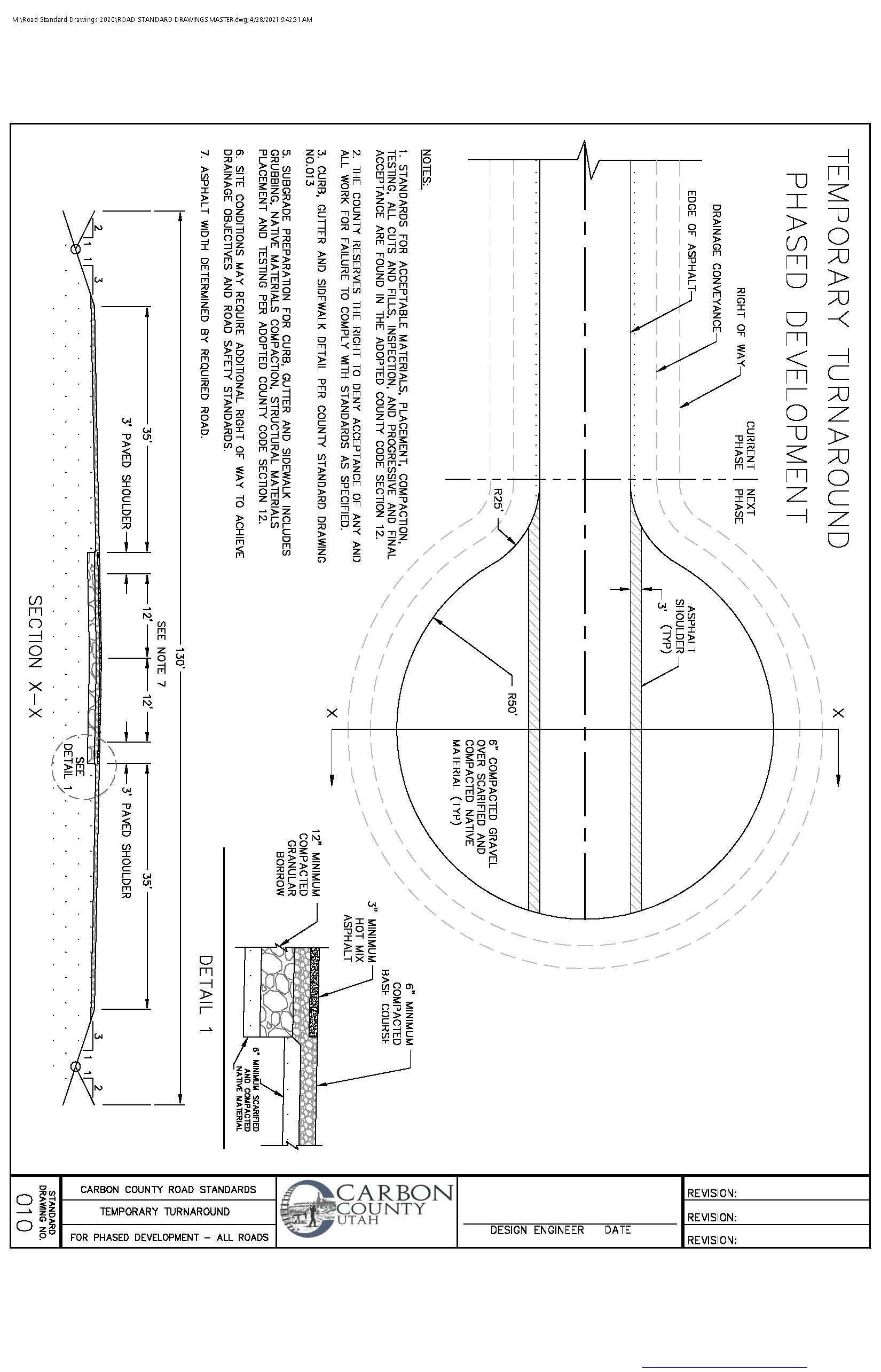
Temporary turnarounds shall be required on all streets which are intended to be extended in the future and which exceed three hundred lineal feet (300') from the centerline intersections of the closest intersecting street.
- The development shall provide additional right-of-way or any easements necessary to construct and maintain the required temporary turnaround area.
- If a temporary turnaround is not extended within one year from the final inspection, then it must be asphalted by the developer.
- Cul-de-sacs and dead ends or streets which are temporarily terminated shall be limited in length as determined by the County Engineer and Road Department.
- Such streets must be terminated by a turnaround of 100 feet (100') in diameter at the property line and 40.5 feet (40.5') radius to back of curb.
- If surface water drains into the turnaround due to the grade of the street, necessary catch basins, drainage systems, and easements shall be provided.
- Where a street dead-ends against property which is not part of a subsequent development phase, a tum around with a permanent easement or right-of-way (from the adjacent property owner) shall be installed.
- Additional rights-of-way may be required to sustain future development.
HISTORY:
Ord. 539, 6/17/2020
Ord. 545, 3/17/2021
12.14.0 Asphalt Road Patch
- A traffic control plan shall be submitted to and approved by the Carbon County Traffic Engineer prior to any work in the Right-of-Way.
- Patches thirty two (32) linear feet or less will be patched at the expense of the developer/contractor
- County Road Department will measure and provide the developer with a cost estimate for the cost of the repair
- Recently chip sealed roadway shall be under a three year and recently constructed roads shall be under a five year removal moratorium. Any pavement removal during the moratorium must have the approval of the County Engineer and require:
- If the road has a chip seal coat:
- The chip seal coat shall be reapplied by the developer.
- If multiple road cuts are required for a site plan or a subdivision then:
- The patch shall encompass all trenches and shall extend across the entire roadway.
- Additional pavement removal shall be required if the edge of patch is within two feet (2') of:
- Painted stripe;
- Lip of gutter;
- A curb;
- An existing pavement patch;
- Another saw cut;
- Poor conditioned asphalt near the new patch.
- Asphalt pavement shall be placed when the temperature is greater than 50 degrees Fahrenheit and rising by 10:00 a.m.
- Cease paving if air temperature falls below 50 degrees Fahrenheit.
- The new patch shall have the following associated thickness:
- Match existing aggregate base;
- Match existing asphalt thickness plus one inch (l ");
- Minimum asphalt patch thickness shall be four inches (4");
- Maximum asphalt patch thickness shall be seven inches (7").
- Compact the asphalt to a relative density of 94 percent (94%) per ASTM D 2041 with no density test results less than 92 percent (92%) or higher than 96 percent (96%).
- Complete compaction before asphalt temperature drops below 180 degrees Fahrenheit.
- Refer to APWA section 32 12 16.13 Plant-Mix Asphalt Paving for lift thickness tolerance.
HISTORY:
Ord. 539, 6/17/2020
Ord. 545, 3/17/2021
12.15.1 Storm Drainage
Responsible development practices require that developers evaluate and mitigate impacts to adjacent properties and systems that are attributable to their development.
- A Hydrology Study/ Drainage Concept Plan (Study) will be required to determine adequate facilities to convey pre-development flows while mitigating increases due to development. The Study will compare pre-development and post-development conditions for a NOAA 25-year 1-hour rainfall event. Increased storm water runoff due to development must be mitigated prior to discharge from the proposed development. Flows must be discharged to adjacent properties without increasing peak runoff, without diversion of flow and without changing runoff characteristics (i.e. concentrated flow, sheet flow, etc.)
- The Study will be reviewed with the criteria set forth in section 12.15.2, 12.15.3, and 12.15.4 below. Each development will be evaluated based on site specific conditions and the Study may be required to address the conditions described in section 12.15.2, 12.15.3, and 12.15.4. Other site specific conditions may need to be addressed that are not mentioned below.
HISTORY:
Ord. 539, 6/17/2020
Ord. 545, 3/17/2021
12.15.2 Drainage Maps
- Provide a copy of the most recent plat map submitted to the Planning Department. Pre and post development maps must be consistent with the plat map.
- Both a pre-development and post-development drainage map are required to be submitted as part of the Study. They should include the following: north arrow, scale, contours, a title block that reads "Drainage Concept I Hydrology Study Map for 'The Name of the Subdivision as it appears on the Plat". The title block should also address for whom the study was prepared, the engineering firm that prepared it, and the licensed engineer doing the work. These maps should include a location map, and should show and label all existing and proposed easements and rights of way for the subject property including all existing and proposed utility easements and all existing and proposed utilities.
- Any drainage improvements or conveyances within a utility right-of-way will require an easement from the utility company or entity granting permission to enter, construct and maintain any proposed improvements. Any such letters are to be included in the report as an Appendix. If applicable, provide a signature block on the post development map for approval by the affected entity.
- On-site areas shown on the drainage maps must be of a scale not greater than 1" = 100'. Off-site areas must be at a scale of not less than 1" = 500'.
- Provide Civil Engineer's "wet" signature, stamp and expiration date on both the pre development and post development maps.
- Provide a table showing the hydrologic design data used to calculate the flows on the drainage map and in the report (i.e., storm frequency, rainfall depth, soil type, percent imperviousness, etc.).
- Provide clear and adequate topography to support area boundary determinations. Provide adequate off-site topography to determine existing off-site drainage patterns. Topography must be accurate enough to verify drainage boundaries and conditions on adjacent properties. Clearly show ridgelines that define sub-basins. Identify existing and proposed drainage patterns using arrows on maps.
- Show and label subarea boundaries and acreages for each subarea. Boundaries of individual subareas should be uniquely outlined with color.
- Label all existing and proposed ditches, culverts, storm drains, curb inlets, V-ditches, swales, down-drains, terrace drains, J-walls and other drainage features and conveyances with percent slope, diameter, cross-section, dimensions, type and material as applicable. Identify flows tributary to each conveyance in cubic-feet per second. Verify adequacy of all existing and proposed improvements to accept and convey flows for pre-development and post-development conditions.
- Determine whether channel protection will be required for ditches conveying flows throughout the project.
- With plan and profile sheets, demonstrate that proposed storm drain alignment and ditches have been evaluated and adjusted to avoid utility conflicts.
- Clearly indicate on pre-development and post-development maps the summation of flows (EQ) and summation of area (EA) at the collection point of each sub-area, at locations where sub-areas collect and convey flows, where flows enter detention I retention basins, and where flows leave the site for conditions before and after development.
- Mitigate any increase in runoff with a detention/ retention basin or obtain drainage acceptance letters from all affected downstream property owners to the first natural drainage course with adequate capacity as demonstrated by the design Engineer.
- Publicly maintained drainage improvements and conveyances are not allowed outside of road right-of-ways without a drainage easement or right-of-way for maintenance as determined by County Engineer and County Road Department Supervisor.
- Clearly label maintenance responsibilities for all existing and proposed drainage facilities.
- Show and label street locations, names and slopes; provide typical sections on map and in report.
- Provide a table to list all of the characteristics of each subarea such as, area (acres), time of concentration (minutes), percent impervious, flow (cubic feet per second), etc.
- Delineate area of inundation and maximum ponding depth for all detention basins and areas designed for controlled inlet restriction.
- Provide and show adequate access to inlets and outlets of proposed detention basins, storm drains and other conveyance devices that will require maintenance.
- Debris laden and bulked flows will not be allowed into closed systems.
- Evaluate the site for any flood hazards and delineate on maps and on the Plat Map.
- Delineate any flood hazard limits on the property. Improvements in these areas will require appropriate mitigation measures. If not applicable, add "Note: Project site not subject to Flood Hazard."
- Delineate the FEMA Flood Zone "A'' limits, if applicable, on the property. If not applicable, add "Note: Not within FEMA Flood Zone "A". This should be shown on the pre-development and post development maps and the Plat Map.
HISTORY:
Ord. 539, 6/17/2020
Ord. 545, 3/17/2021
12.15.3 Calculations
- Submit a hydrology study report which should include, but not be limited to the following: project description, existing and proposed drainage conditions, backup and reference materials (highlighted), and complete calculations including software input/output files. Clarify methods and software used to calculate pre and post development runoff. Provide a conclusion describing your project with mitigation measures undertaken and impacts to downstream systems and properties.
- A pre-development and post-development hydrology study is required to determine increases in flow and volumes to determine impacts to downstream systems and/or properties.
- Provide inflow and outflow hydrographs and calculations to determine required storage volume for detention/ retention basins. Label location and limits of inundation on map.
- Double inlet capacity is required where sump conditions exist.
- Maximum ponding depth for parking lots is 6 inches. Loading dock areas in commercial developments are allowed 18 inches ponding maximum.
- Detention/ retention may be required on-site due to downstream restrictions.
- Erosion protection may be required to protect graded slopes.
- Show velocity at all points where flow leaves the site for existing and proposed conditions. Increase in velocity is not allowed.
- On the Drainage Concept Map and in the report show the velocity at the outlet(s) for the existing and proposed conditions. No increase in velocity is allowed.
- Based on site conditions, additional calculations may be required for existing and proposed conditions for 2, 5, 10, and 50 year storm events.
- Based on site conditions, HEC-RAS analysis may be required to determine flood hazard limits.
- Letters of permission are required for:
- Any off-site work required as part of an approved Hydrology Study/ Drainage Concept report or maps.
- Any work ·within a public agency/ utility provider easement or right-of-way.
- Any work within a flood control easement; and
- Any proposed plans to divert or change existing flow volumes or patterns causing an effect on adjacent or downstream properties.
Any such letters are required to be signed and notarized and included in an appendix to the report.
HISTORY:
Ord. 539, 6/17/2020
Ord. 545, 3/17/2021
12.15.4 Detention/Retention Basins
The Hydrology Study/ Drainage Concept Plan (Study) will be required to determine adequate facilities to convey pre-development flows while mitigating increases due to development. The Study will compare pre-development and post-development conditions for a NOAA 25-year 1-hour rainfall event. Increased storm-water runoff due to development must be mitigated prior to discharge from the proposed development. Flows must be discharged to adjacent properties without increasing peak runoff, without diversion of flow and without changing runoff characteristics (i.e. concentrated flow, sheet flow etc.)
Often part of the mitigation includes the construction of a detention or retention basin, and the County Engineer may require the construction of such basin in conjunction with approval of the hydrology drainage study. The design, calculations and drawings are to be included in the required report.
The following is a list of basic requirements that should be used in a basin design. Each site is unique and additional requirements may be necessary as determined by review. The report should include, but not be limited to the following critical elements:
- Backup and reference materials supporting assumptions and parameters, a printout of calculations including software input/output files and/or spreadsheets. Clarify methods and software used to calculate pre and post development runoff and the design of the detention/retention facilities and appurtenant structures.
- Provide inflow and outflow hydrographs and calculations to determine required storage volume for detention basins.
- A drawing with the following elements is required:
- Clearly indicate ΣQ and ΣA at the inlet and outlet of the basin. Delineate area of inundation and maximum ponding depth for all detention basins and areas designed for controlled inlet restriction.
- Identify height of freeboard and location of spillway for all detention/retention basins.
- Provide and show adequate access to inlets and outlets of proposed detention basins, storm drains and other conveyance devices that will require maintenance.
- Clearly label maintenance responsibilities for all existing and proposed drainage facilities.
- Provide a drawing of the proposed detention facility with contours, cross sections, volume required, volume provided and elevations, and slope of the basin floor to the inlet. Include details for the outlet works including the restricted orifice, inlet protection (i.e. headwall or riprap), manholes and other appurtenant elements.
- Provide a cross-section detail of the basin that illustrates or calls out the top of embankment elevation, top of spillway elevation, maximum ponding depth and elevation, and embankment slope upstream and downstream.
- Provide a conclusion describing your project and impacts to downstream systems and properties. Include measures taken to fully mitigate increases in drainage due to the proposed development.
- An authorization letter from any utility company or public agency is required for encroaching within their right-of-way.
- The volume requirements of detention/retention facilities shall not be reduced based on evaporation or infiltration due to percolation.
- A maintenance plan shall be submitted with any proposed basin.
- All detention / retention basin facilities must be designed to accommodate an emergency overflow that safely conveys flood waters to a nearby street or other acceptable facility.
- If no adequate outlet can be determined, a retention basin will be required that provides double the design storm capacity with an additional 1-foot of freeboard above the designed water surface elevation to the spillway crest.
- Side slopes of a detention/retention basin shall be 3:1 maximum.
- Cross slope within a basin shall be steep enough to provide adequate drainage to the nearest outlet structure. Under no circumstances shall the slope be less than 1% across any portion of the basin.
- The use of pumps to drain storm water facilities will not be allowed due to excessive and continual maintenance costs.
- Submission of ''as-built" drawings to the Carbon County Engineer for all storm water facilities is required.
- Above ground detention systems are permitted in Carbon County.
- Underground detention facilities are permitted in Carbon County.
- Underground retention facilities are permitted in Carbon County.
- Soils test are to be performed and shall indicate soil type and location of the ground water level.
- Storm water drainage system shall be accessible through manholes, inlets, inspection ports, or by other outside entry means for inspection, maintenance, or repair of the facility.
- Control structures shall provide a means if a portion of the structure becomes clogged or otherwise inoperable; the detention facility will still operate in an emergency flow operation.
- The underground retention system must have a lo\v maintenance system to handle sediment, debris, and other particles.
- A soils report will be required to indicate if the water will infiltrate in a reasonable amount of time.
- The infiltration shall not be used as outflow when calculating the storm water capacity.
- A retention or detention pond will require a monitoring and maintenance plan to be submitted to the County.
HISTORY:
Ord. 539, 6/17/2020
Ord. 545, 3/17/2021
12.16.1
Culverts shall be a minimum of 18 inches unless approved by the County Engineer and County Road Supervisor.
HISTORY:
Ord. 545, 3/17/2021
12.17.0 Subgrade Preparation
This work shall consist of the shaping and compacting of the subgrade in accordance with these specifications and in conformity with the lines, grades, and typical cross sections shown on the drawings or as established by the County Engineer and Road Department.
HISTORY:
Ord. 539, 6/17/2020
Ord. 545, 3/17/2021
12.17.1 Clearing And Grubbing
Remove between four (4) and six (6) inches of topsoil and organic material then the surface shall be scarified to a depth of six (6) inches and compacted to the equivalent of ninety-six (96%) percent of the maximum dry density. No organic material, soft clay, spongy material or other deleterious material will be permitted in this scarified subgrade layer. Rough subgrades shall be shaped and graded wo within a tolerance of 0.15 feet of design grade and drainage shall be maintained at all times. The developer shall provide to the County Engineering or his designee the results of a sub-surface investigation performed by the developer's Engineer and the recommendation as to whether existing material is adequate for road construction.
HISTORY:
Ord. 539, 6/17/2020
Ord. 545, 3/17/2021
12.17.2 Removal Of Spongy Material
Removal of wet and spongy soils shall be mitigated. After removing the material, the ground shall be proof rolled a minimum of three (3) times.
HISTORY:
Ord. 539, 6/17/2020
Ord. 545, 3/17/2021
12.17.3 Cut And Fill
All fill imported shall have density testing conducted in one (1) foot lifts, and not to exceed fifty (50) feet in length.
- Cut and fill inspections. The County Engineering or his or her designee shall inspect subgrade prior to any fill being placed.
HISTORY:
Ord. 539, 6/17/2020
Ord. 545, 3/17/2021
12.17.4 Compaction
Following roadway excavation the subgrade shall be proof rolled by running moderate weight rubber tire mounted construction equipment uniformly over the surface at least three times. During the rolling operation moisture content of the subgrade layer shall be maintained at not less than 97% or more than 105% of the optimum moisture content. Testing will be required to ensure compaction is 96% or greater. Rolling shall be continued until the entire roadbed is compacted to the specified density to a minimum depth of 8 inches.
HISTORY:
Ord. 539, 6/17/2020
Ord. 545, 3/17/2021
12.17.5 Acceptance Of Subgrade Preparation Work
Prior to acceptance of all subgrade preparation, density and testing reports shall be submitted before granular borrow and any other material placed.
HISTORY:
Ord. 539, 6/17/2020
Ord. 545, 3/17/2021
12.18.0 Granular Borrow
Granular borrow material shall consist f well graded granular bank run natural aggregate material with a maximum size of 6 inches and less than 15% passing a No. 200 sieve or as approved by the County Engineer and Road Department. The material shall meet the following gradation:
Sieve Size
Percent Passing
No. 10
50% max
No. 40
30% max
No. 200
15% max
The granular borrow material shall be compacted to not less than 96% maximum dry density as determined by AASHTO T-99. Granular foundation borrow shall be compacted to not less than 95% of maximum dry density as determined by ASTM D1557. Surfaces shall be true to the established grade with thickness being not less than 1/4 inch from the required layer thickness and with the surface elevation varying not more than 3/8 inch in ten feet from the true profile and cross section.
HISTORY:
Ord. 539, 6/17/2020
Ord. 545, 3/17/2021
12.19.0 Base Course
The base course shall be made, placed, graded and compacted in accordance with the Utah Chapter of the American Public Works Association (APWA) Manual of Standard Specification, latest edition including latest addendum, Section 32 11 23 Aggregate Base Course. APWA Target Gradation shall be Grade 1. Placement shall be per the APWA Standard or as approved by the County Engineer and Road Department.
HISTORY:
Ord. 539, 6/17/2020
Ord. 545, 3/17/2021
12.20.0 Bituminous Asphalt Pavement
The bituminous asphalt shall be mixed and placed in accordance with the Utah chapter of the American Public Works Association (APWA) Manual of Standard Specification, latest edition including latest addendum. The following sections shall apply, with the exception of asphalt thickness shall not be less than 3 inches:
- Section 32 12 03 Asphalt Binders;
- Section 32 12 05 Bituminous Concrete;
- Section 32 12 13.13 Tack Coat;
- Section 13 12 13.19 Prime Coat;
- Section 32 12 16.13 Plant-Mix paving.
The County Engineer and Road Department will approve the Developer/Contractor with the current approved mix design from the APWA manual. Each paving job will require a ticket or chart from the asphalt plant showing the content of each load of asphalt.
HISTORY:
Ord. 539, 6/17/2020
Ord. 545, 3/17/2021
12.21.0 Contact Surface
Contact surface of curbing, gutters, waterways, manholes and other structures, shall be painted with tack coat consisting of a cut back asphalt grade RC250 or SS-1 immediately before the paving materials are placed against them. Care should be taken during application to prevent the tack coat from being applied to exposed concrete above the contact surfaces.
Any overlay of existing asphalt with or without paving fabric shall have a tack coat applied prior to application of any bituminous asphalt material.
Immediately adjacent to gutters, manholes and other structures, the bituminous surface course shall be spread uniformly high, so that after compaction it will be slightly above the edges of such structures. Along curbs, gutters, manholes and other places inaccessible to the roller, the materials shall be thoroughly compacted with hand tampers, but extreme care shall be exercised to prevent damaging the adjacent surfaces.
HISTORY:
Ord. 539, 6/17/2020
Ord. 545, 3/17/2021
12.22.0 Adjusting Manholes And Valve Boxes To Final Grade
This section covers the requirements for adjusting manholes and valves to final grade. The adjustment shall be made with cast iron ring inserts, concrete grade rings or cast-in-place concrete rings or squares. Cast-in-place concrete rings or squares shall be constructed after the asphalt surface has been placed.
- Concrete shall be Class AA(AE). The concrete mix shall be one-part cement to two parts sand or Kent Seal.
- Manholes and valves in asphalt surfaces shall have the cast iron ring and cover constructed such that the cast iron ring is one-sixteenth inch (1/16th") lower than the existing or new pavement. Manhole rings shall be set to the grade and slope of the road, adjustable grade rings may be needed to meet slope and grade.
- Where manholes are to be raised this is to be accomplished by removing the cover and frame and raising the manhole to proper elevation with concrete.
- Rings and covers shall be protected during backfilling and compaction of the soil and during the placing or replacing of road surfaces. Any ring or cover loosened from the manhole section shall be reset in cement mortar and any ring or cover damaged or broken shall be replaced by the Developer/Contractor at its expense.
HISTORY:
Ord. 539, 6/17/2020
Ord. 545, 3/17/2021
12.23.0 Asphalt Surface Treatments
The asphalt surface treatments shall be mixed and placed in accordance with the Utah Chapter of the American Public Works Association (APWA) Manual of Standard Specification, latest edition including latest addendum. The following sections shall apply:
- Section 32 01 13.61 Slurry Seal;
- Section 32 01 13.64 Chip Seal;
- Section 32 01 13.52 Mastic Seal;
- Section 32.01 13.50 Fog Seal;
- Section 32 01 13.68 High Density Mineral Bond Seal.
The County Engineering and Road Department will provide the Developer/Contractor with the mix design from the APWA manual based on location and time of year placed.
HISTORY:
Ord. 539, 6/17/2020
Ord. 545, 3/17/2021
12.24.1 General
Street and informative signs dealing with traffic control and information shall be designed with cooperation between the developer and the County.
HISTORY:
Ord. 539, 6/17/2020
Ord. 545, 3/17/2021
12.24.2 Layout And Design
The layout, design and requirement for all street signage will be determined during platting or site plan design portion of a project. The requirement for caution, hazard, speed and other information signs will also be determined during the project review process.
HISTORY:
Ord. 539, 6/17/2020
Ord. 545, 3/17/2021
12.24.3 Sign Procurement
The Developer/Contractor for any given project is responsible for the procurement of all street signage required within a project area or outside of a project area if the need for the sign is determined to be due to the nature of the project being developed.
HISTORY:
Ord. 539, 6/17/2020
Ord. 545, 3/17/2021
12.25.0 Landscaping Requirements
The following landscape provisions shall be adhered to by all land uses unless otherwise noted:
- Park Strips. Park strips adjacent to residential dwellings shall be landscaped and maintained by the property owner whose property abuts the park strip.
- Landscape Maintenance. All landscaped areas shall be maintained by watering of landscaping, removal of weeds, the cutting of lawn or any other activities required to maintain healthy and aesthetically pleasing landscaping. Topping of trees as a pruning technique is prohibited.
- Tree Clearance. Trees which project over any county right of way or sidewalk shall be pruned clear of all branches between the ground and a height of eight feet for that portion of the foliage located over the sidewalk.
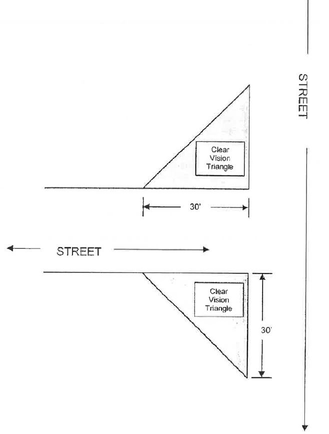
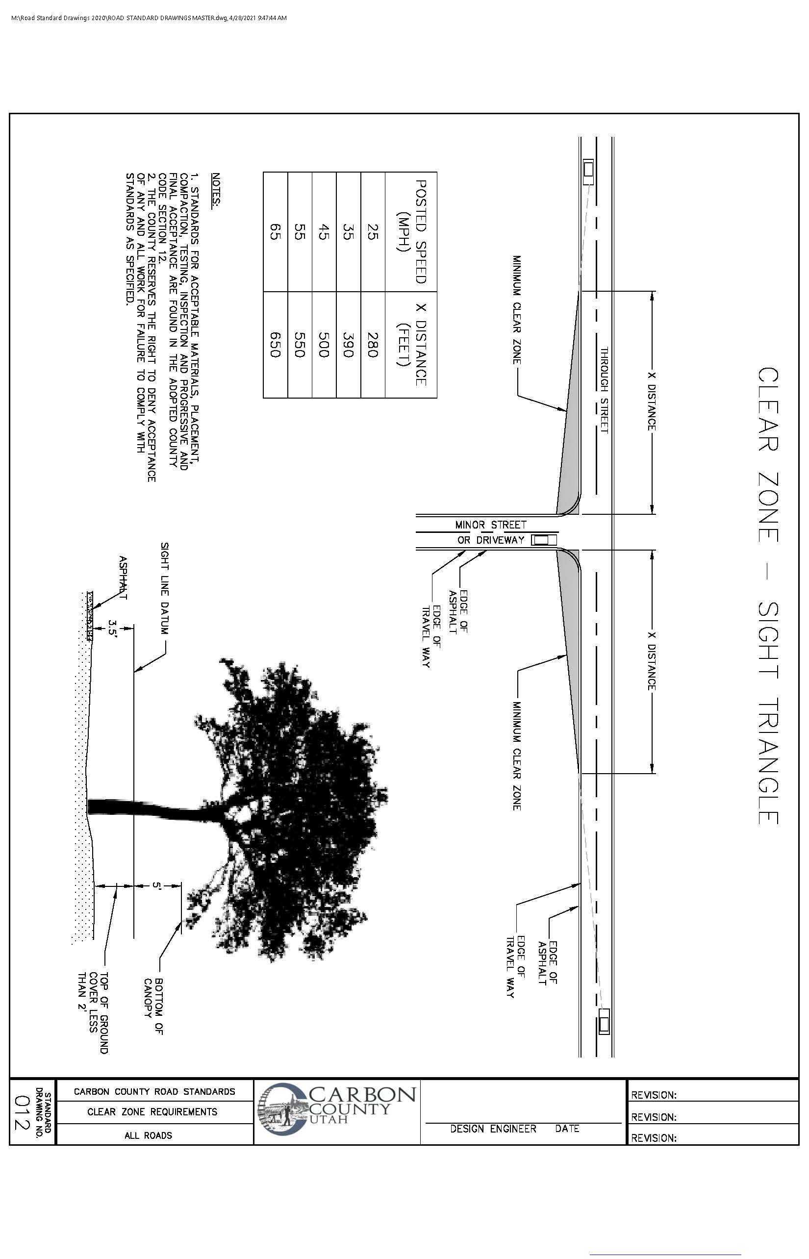
- Clear Vision Triangles. No landscaping over three feet in height shall be allowed within a clear vision triangle except trees with single trunks that are pruned such that all branches and foliage are removed to a height of at least eight feet.
HISTORY:
Ord. 539, 6/17/2020
Ord. 545, 3/17/2021
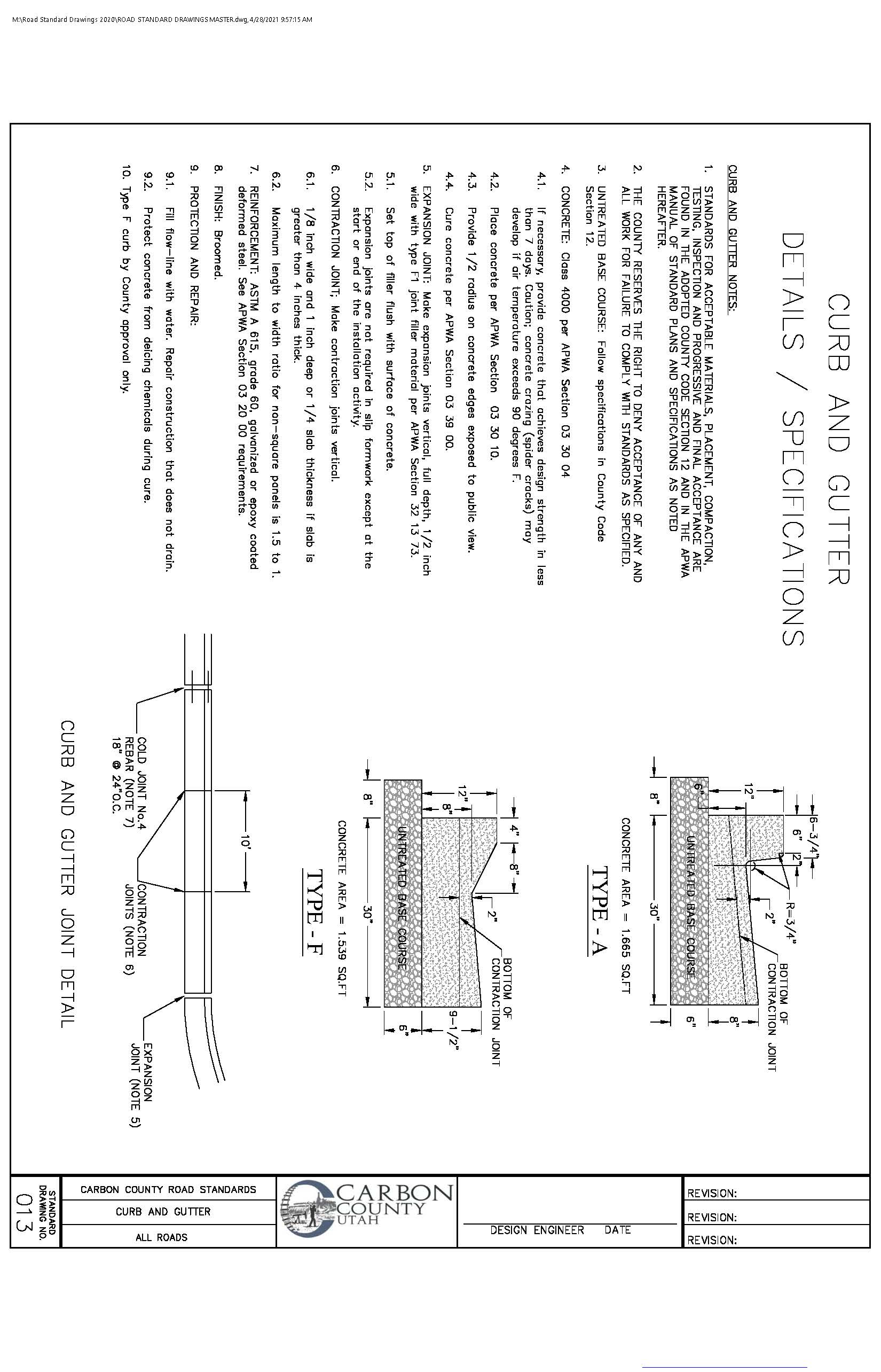
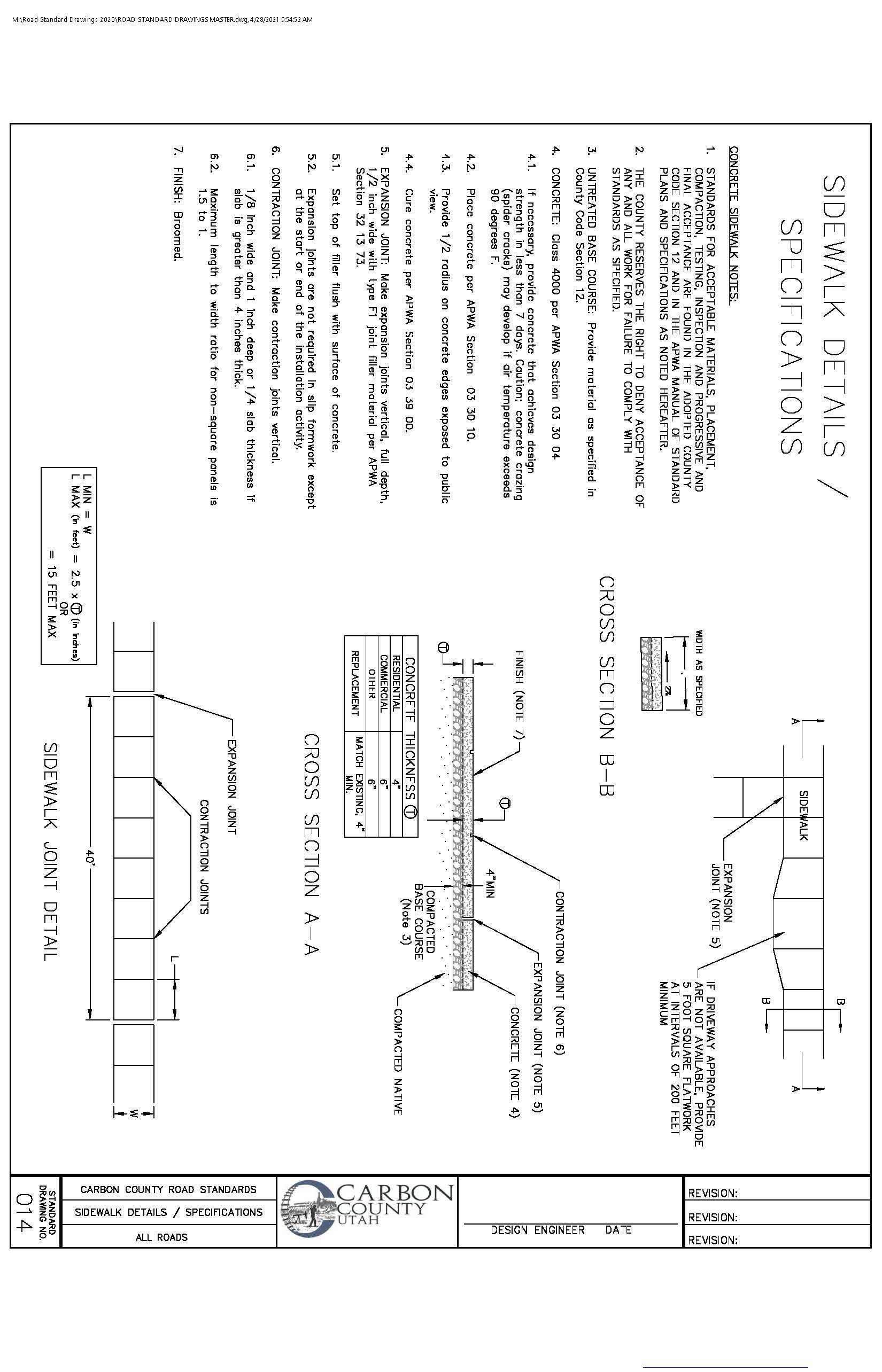
12.A.1 Standard Drawings
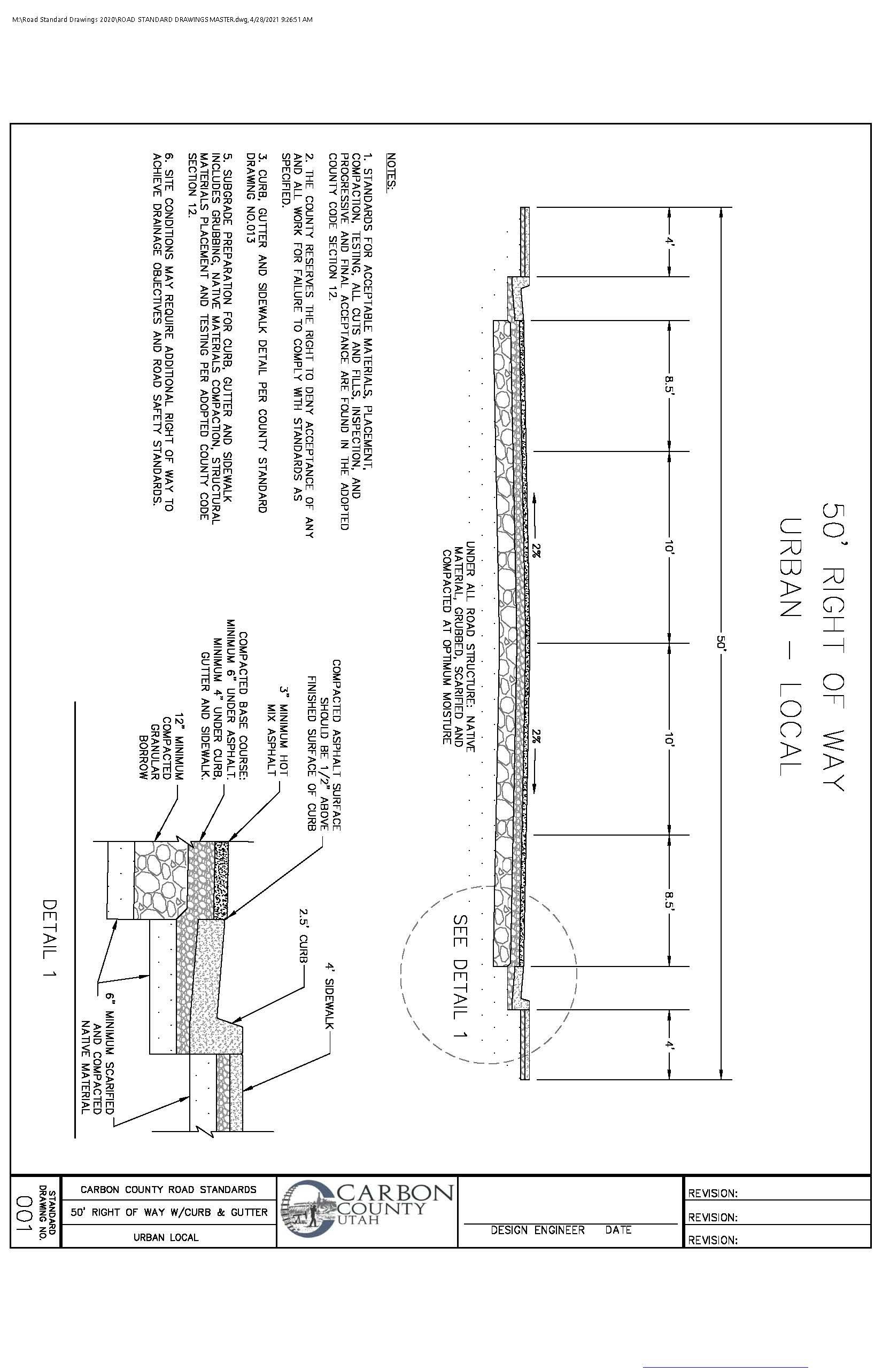
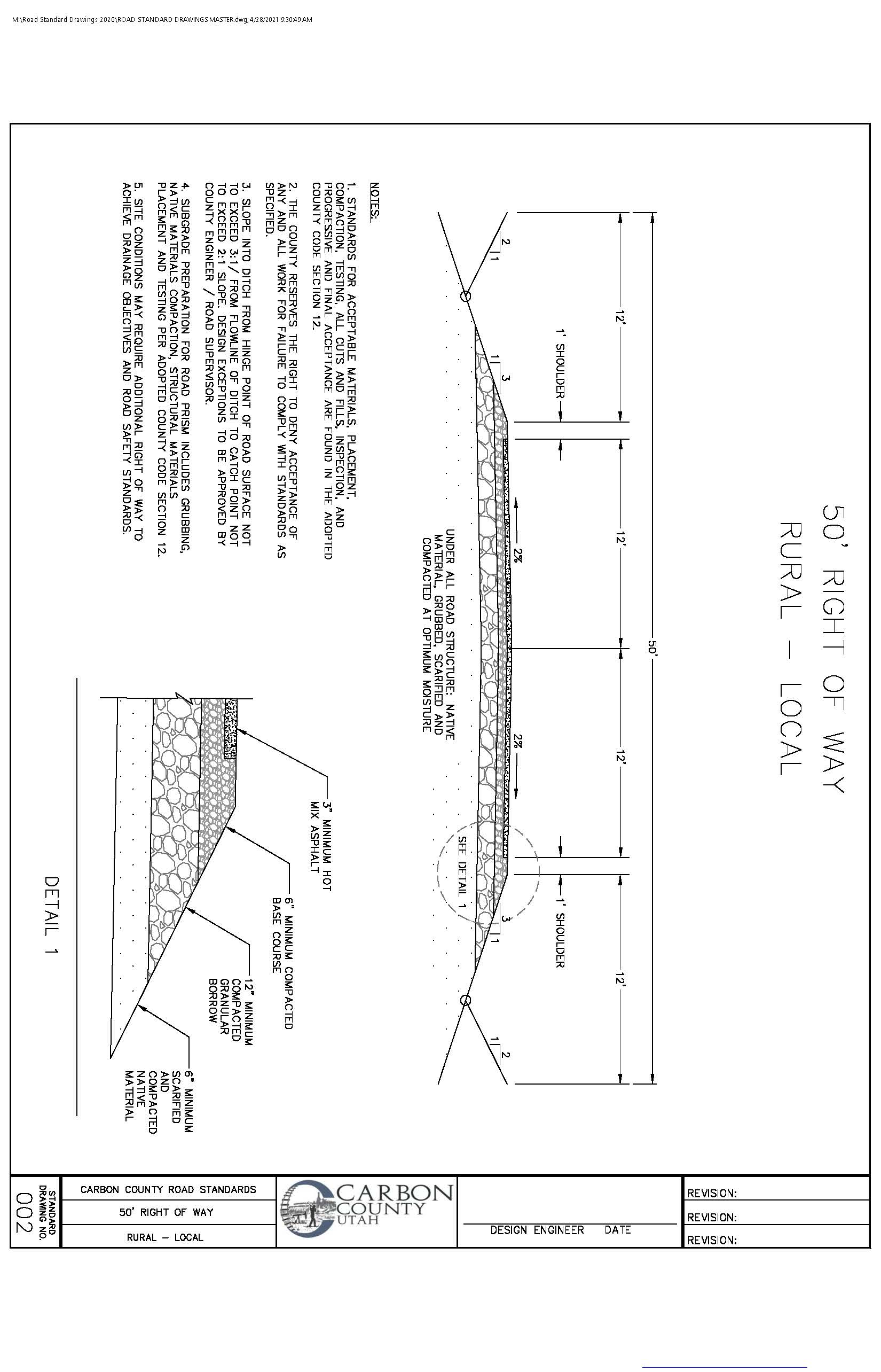
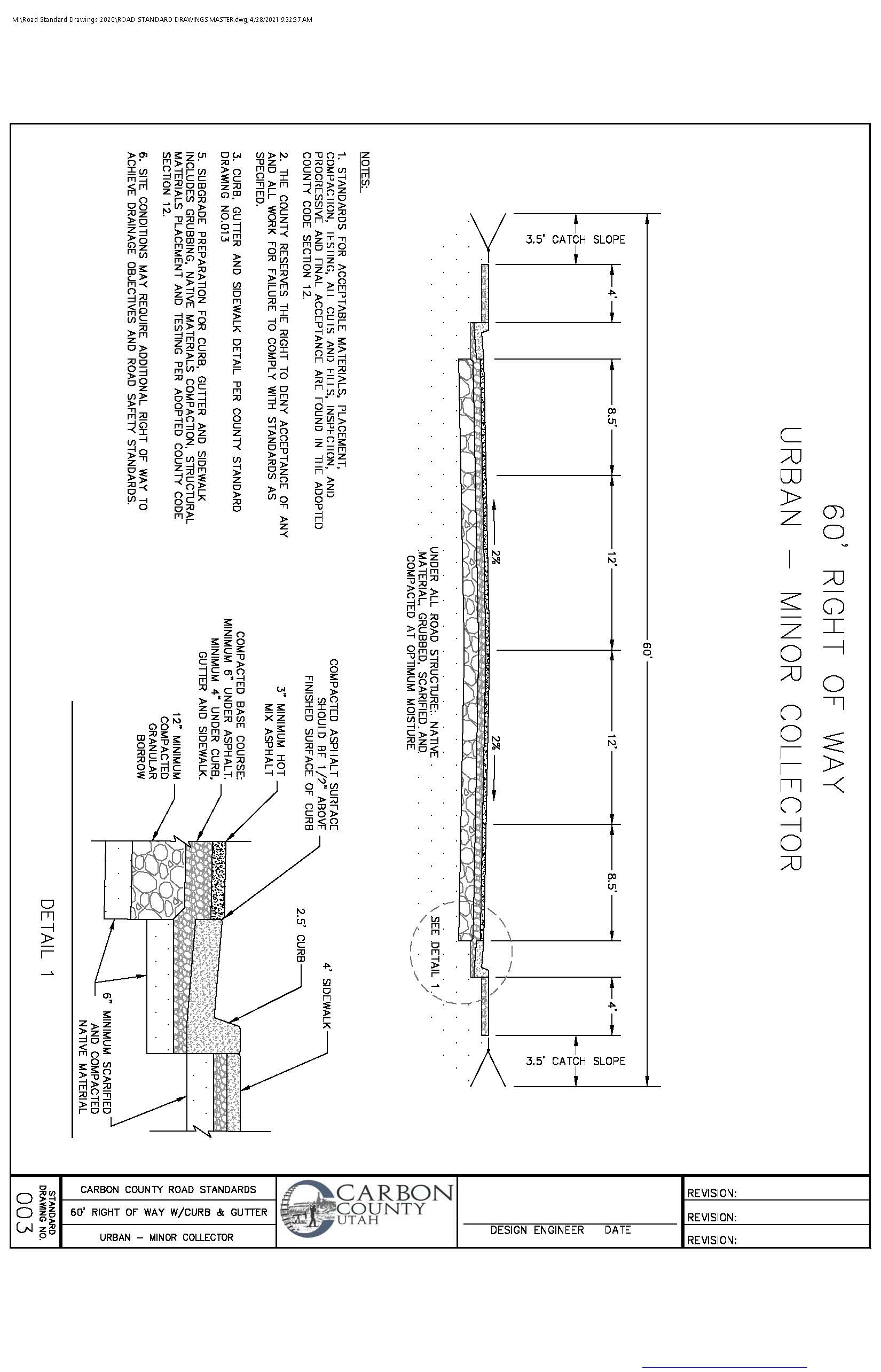
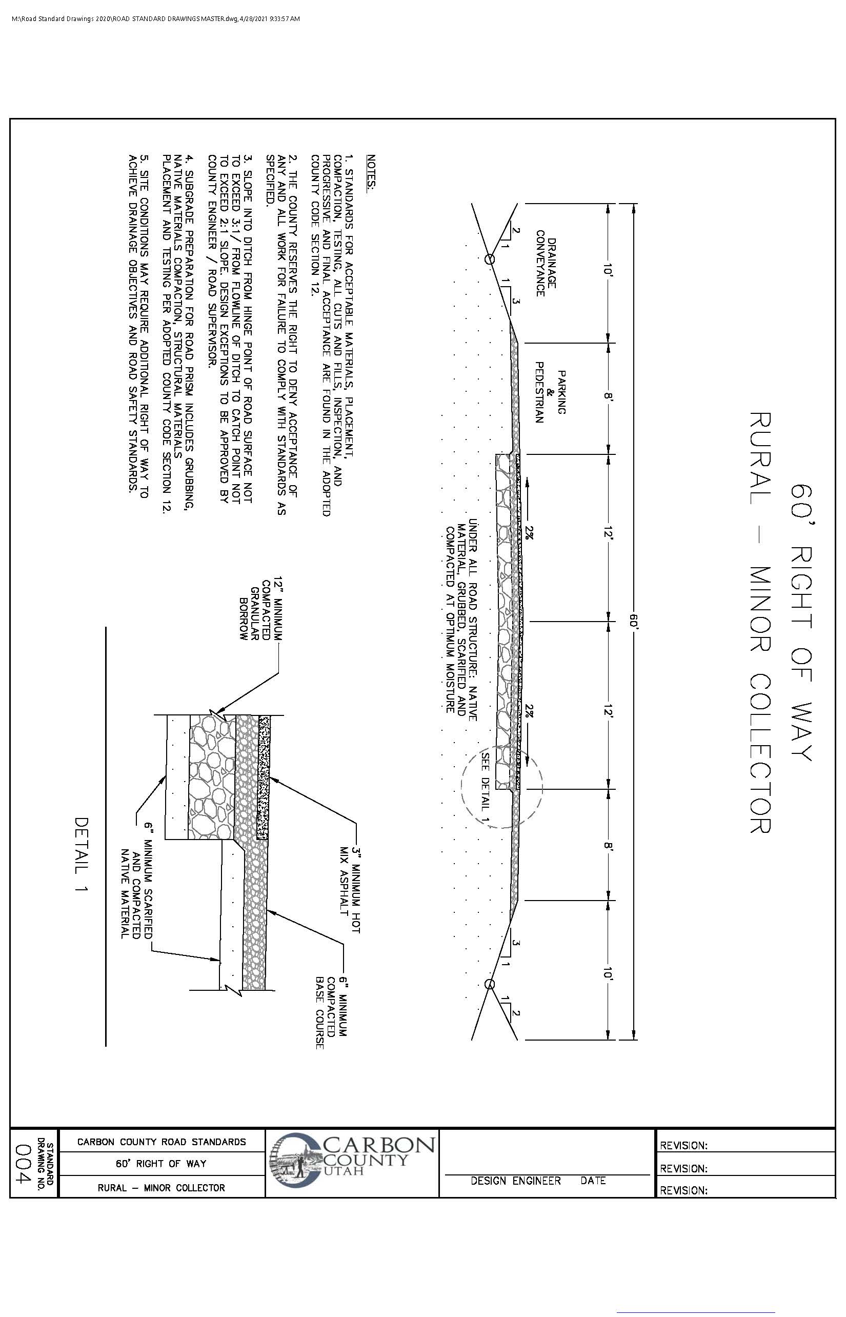
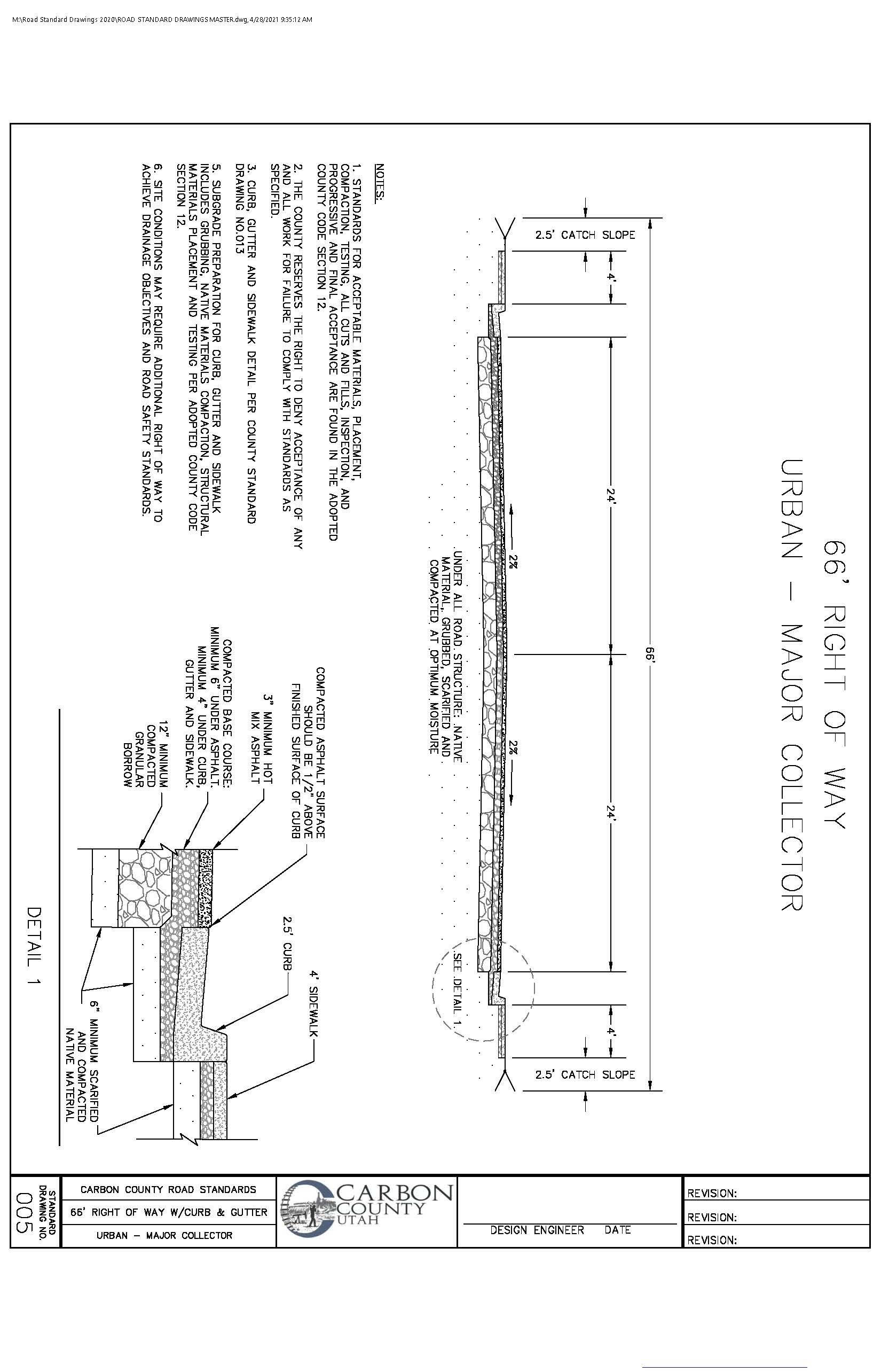
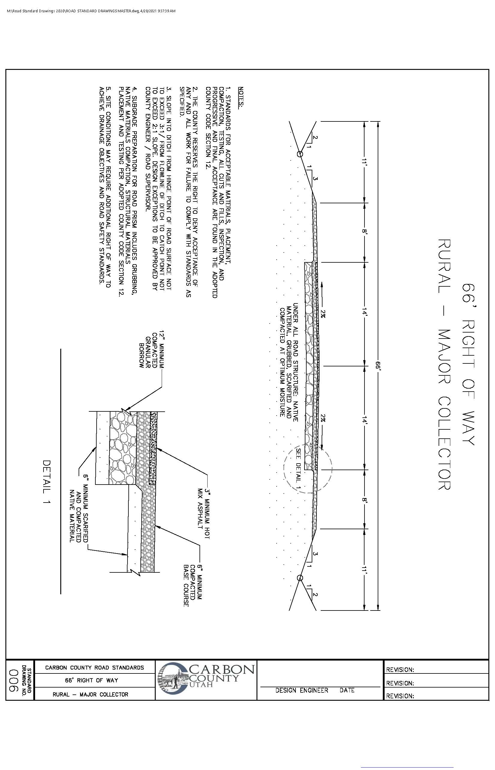
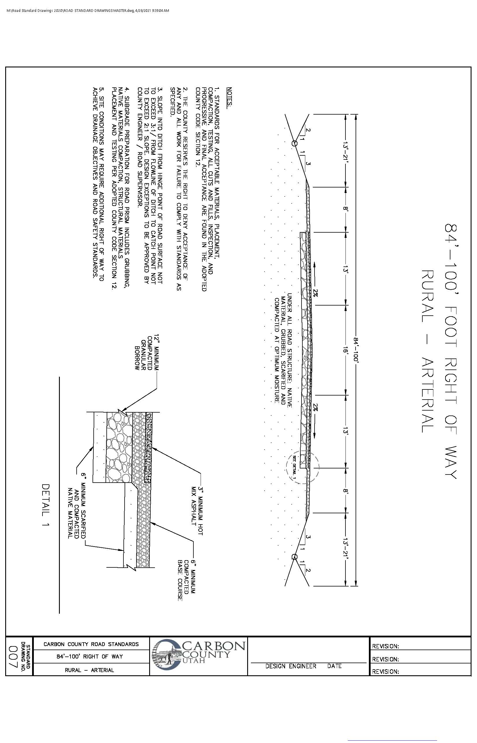
HISTORY:
Ord. 539, 6/17/2020
Ord. 545, 3/17/2021