
Allen City Zoning Code
APPENDIX I
TRAIL DESIGN STANDARDS
A.
Hard surface trails.
1.
Design objectives.
The alignment should follow the contours of the land and the natural drainage patterns. The trail should not appear to be carved out of the terrain.
Trails should be gently curvilinear, and may include a combination of radii and straight segments. Serpentine or sinuous trail alignments are not desirable and should be limited to instances where tree preservation necessitates such alignments.
Meanders in trails should appear to have a purpose, and should not be haphazard or regular.
Create functional, efficient circulation patterns that present and preserve the natural terrain and vegetation to the greatest extent possible.
Locate intersections at natural focal points such as scenic vistas and convenient access points. Design 90-degree trail intersections with turn radii at a minimum of ten feet. Larger turn radii may be acceptable when trails intersect at planting beds, signage, or other focal points.
Where conditions apply, trails shall align with existing or future crosswalks at streets. These intersections shall incorporate handicap accessible ramps that meet the design criteria of the Americans with Disabilities Act.
2.
Design standards.
a.
Prepared subgrade. Over-excavate unstable subgrade soils where encountered and replace with city-approved fill material. Compact all fill to 95 percent standard proctor @ -2 percent to +4 percent optimum. Remove all topsoil prior to subgrade preparation and use in finish grading work along trail edges after concrete has cured. Import additional soil backfill as needed for trail edges to provide a minimum five-foot-wide trail shoulder and an embankment blended with existing grade on both sides of the trail. All embankments must be constructed at mowable slopes (4:1 grade or less).
b.
Pavement structure. The standard pavement is reinforced Portland cement concrete (concrete mix: Five-sack, 3,000 pounds/square inch minimum, three to five-inch slump, ten percent fly ash content maximum) with a transverse light to medium broom finish. One inch (14 mm) redwood expansion joints shall be placed in the trail at an interval of 40 feet in ten-foot-wide trails and 48 feet in 12-foot-wide trails. Expansion joints shall be topped and sealed with a minimum thickness of one-quarter-inch elastomeric sealer compound, flush with the top surface of pavement on both sides of the joint. Contraction joints shall be placed at intervals equal to the trail width and shall be of a depth of one-fourth the pavement thickness. The joints shall be saw-cut one-fourth- inch (3.175 mm) wide. For optimum user comfort, the finished surface of trails should not vary more than .02 feet (0.63 cm) from the lower edge of an eight-foot (2.4 m) long straight edge when laid on the surface in any direction. The trail concrete thickness shall be five inches minimum. The reinforcement shall be #3 (minimum) deformed steel bar at a maximum of 16 inches on center, both ways, on chairs (welded wire mesh is not acceptable). Doweled expansion and construction joints, where new trail pavement is connected to existing pavement shall consist of #5 deformed steel bar, spaced at 12 inches o.c. along the pavement joint.
c.
Width and clearance. Trails on which a mix of bicycle, pedestrian and other non-motorized transportation, and large maintenance vehicles, are required to navigate steep grades, should be 12 feet (3.7 m) wide. Otherwise, a ten-foot (3 m) width is adequate. The minimum width of a one-directional bicycle path is ten feet for maintenance access and passing room for cyclists. One-way bicycle paths often will be used as two-way facilities unless effective measures are taken to assure one-way operation.
The optimum vertical clearance of obstructions over a trail is ten feet (3 m) or higher, which accommodates maintenance, patrol, and emergency vehicle access. All underpasses and tunnels should be a minimum of ten feet in height. The standard minimum vertical clearance is eight feet (2.4 m). If vertical clearances under bridges and other structures is less than ten feet, the clearance shall be clearly posted with warning signage to alert approaching trail users. Tree branches over trails shall be cleared to this height unless otherwise directed by the parks and recreation department.
A five-foot minimum (1.8 m) wide graded shoulder shall be constructed and maintained adjacent to both sides of the trail surface. Two feet (0.6 m) is the minimum width for the adjacent graded area; although a three-foot (0.92 m) width clearance shall be provided from trees, poles, walls, fences, guardrails, etc. or their lateral obstructions whenever possible. In instances where trees or other obstacles may encroach within this space, warning signage should be provided. A five-foot (1.8 m) lateral separation is desirable from any embankment that the cyclist would have difficulty encountering. If this is not possible, a positive barrier such as dense shrubbery, safety railing, walls, or fencing shall be provided. All barrier material shall conform to City of Allen standards.
d.
Design speed. Trails intended for bicycle usage should be designed for a selected speed that is at least as high as the preferred speed of the fastest anticipated cyclist. In general, a minimum design speed of 20 miles per hour (32 km/h) should be used when trail grades do not exceed five percent. It is the intent of the plan to design accessible routes linking all destinations and nodes within the city. It is at the discretion of the city to allow for the creation of alternate routes to destinations that may exceed those standards established by ADA. In those instances where strong prevailing tail winds exist or trail grades may exceed five percent, a design speed of 30 miles per hour (48 km/h) is advisable. Speed bumps or similar surface obstructions intended to slow down cyclists which would pose a trip hazard for other trail users should never be used.
e.
Use of soft surface paths and trails by cyclists. Soft surface paths and trails are not to be used by cyclists because of the damage to unpaved surfaces.
f.
Horizontal alignment and superelevation. The minimum radius of curvature negotiable by a bicycle is a function of the superelevation rate of the trail surface, and the speed of the bicycle. The minimum design radius of curvature can be derived from the following formula:
Where: R = Minimum radius of curvature (ft)
V = Design speed
e = Rate of superelevation
f = Coefficient of friction
TABLE 1: MINIMUM RADII FOR PAVED
BICYCLE PATHS
Trails shall not exceed a two percent cross-slope. The city may allow for the construction of additional and alternate routes that exceed the standards established within ADA, provided however, the superelevation does not exceed a five percent slope. Minimum radius varies depending on cross slope.
The coefficient of friction depends upon speed, surface type, roughness, and condition, type and tire condition, and whether the surface is wet or dry. Friction factors used for design should be selected based upon the point at which centrifugal force causes the bicyclist to recognize a feeling of discomfort and instinctively act to avoid higher speed. Extrapolating values used in highway design, design friction factors for paved bicycle paths are assumed to vary from 0.30 at 15 miles per hour (24 km/h) to 0.22 at 30 miles per hour (48 km/h). Friction factors shall be reduced by 50 percent on unpaved surfaces and in areas likely to be wet, shaded, etc.
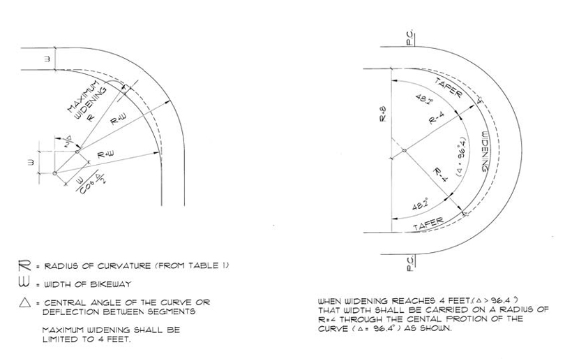
Figure 4. Trail Widening.
When curves of lesser radii than those recommended must be used on bicycle paths because of limited right-of-way, topographical or other considerations, standard curve warning signs and supplemental pavement markings should be installed in accordance with the MUTCD. It is advisable to widen the path in order to increase the lateral space available to cyclists as they lean to the inside of the turn (see Figure 4). The amount of widening should be limited to a maximum of four feet (1.2 m).
g.
Grade. Longitudinal gradients on trails shall not exceed five percent except in unusual circumstances. Alternate routes with grades over five percent and less than 500 feet (152.5 m) are acceptable only when a higher design speed or additional width is provided. In cases where the minimum grade must be exceeded, an alternate trail route must be constructed providing ADA accessibility. The absolute maximum gradient for a trail intended for bike usage is eight percent.
Sustained grades are ideally limited to two percent for multipurpose trails. Grades steeper than three percent should not be used with crushed stone surfaces. Grades of up to five percent are acceptable for bridges with ten-foot (3 m) shoulders or paths where a leveling off at the base of the incline permits adequate recovery before an intersection or other conflict point.
h.
Sight distance. Figure 5 indicates the minimum stopping sight distance for various design speeds and grades based on a total perception and brake reaction time of 2.5 seconds and a coefficient of friction of 0.25 to account for the poor wet weather braking characteristics of many bicycles. For two-way shared use paths, the sight distance in the descending direction, that is, where "G" is negative, will control the design. Use Figure 6 to select the minimum length of vertical curve necessary to provide minimum stopping sight distance at various speeds on crest vertical curves. The eye height of the bicyclist is assumed to be 4.5 feet (1.4 m) and the object height is assumed to be zero as impediments to bicycle travel usually exist at pavement level.
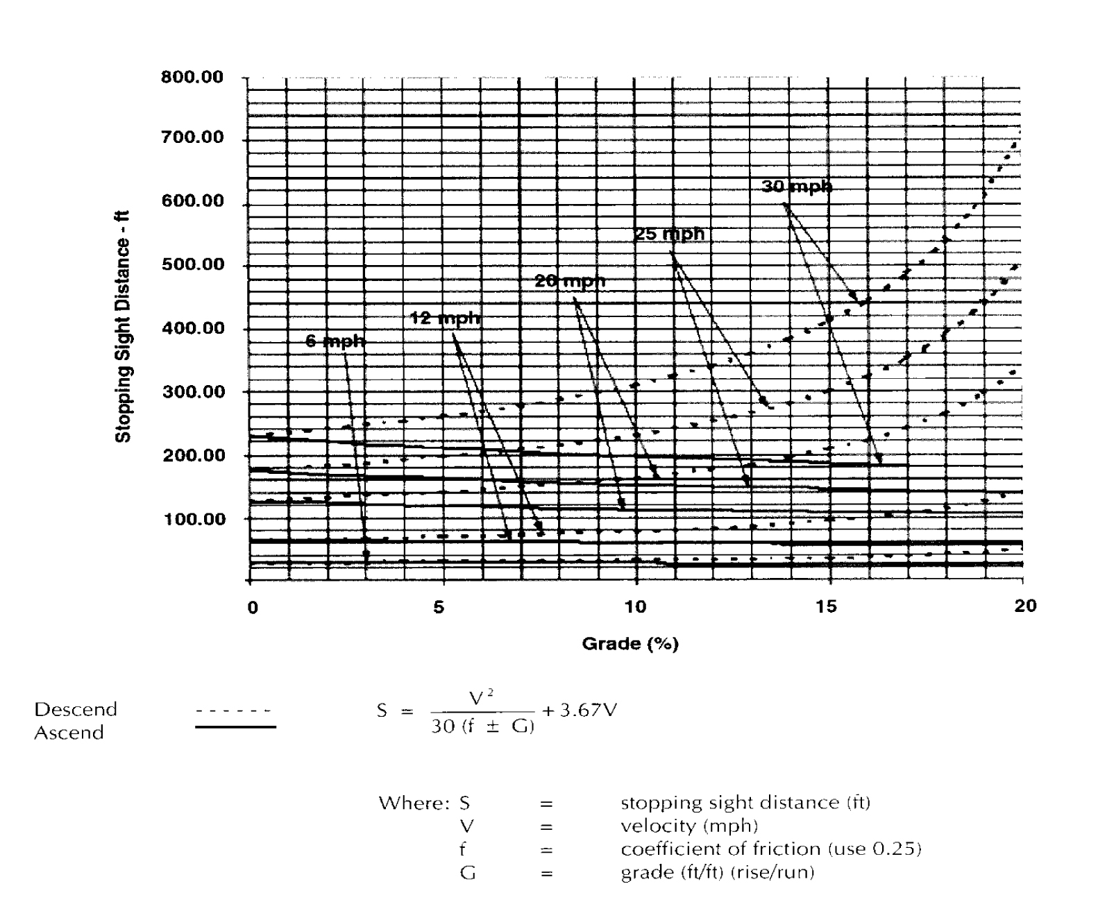
Figure 5.
Figure 7 indicates the minimum clearance that should be used to line of sight obstructions for horizontal curves.
The lateral clearance is obtained by entering Figure 7 with the stopping sight distance for Figure 5 and the proposed horizontal radius of curvature.
Cyclists frequently ride abreast of each other on trails. On narrow trails cyclists have a tendency to ride near the middle of the path. For these reasons, and because of the serious consequences of a head-on bicycle crash, lateral clearances on horizontal curves should be calculated based on the sum of the stopping sight distances for cyclists traveling in opposite directions around the curve. Where this is not possible or feasible, consideration should be given to widening the path through the curve, installing a nonskid yellow center stripe, installing a "curve ahead" warning sign in accordance with the MUTCD (Manual of Uniform Traffic Control Devices), or a combination of these alternatives.
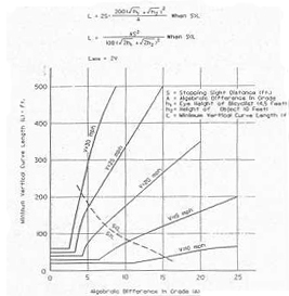
Figure 6. Vertical Curve Length.
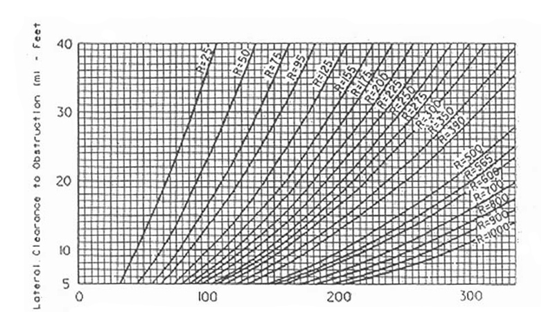
Figure 7. Minimum Lateral Clearance.
i.
Drainage. The trail developer shall install vegetation or other erosion control measures on both sides of the trail and other areas impacted by construction. Erosion control matting or similar materials may be accepted in times of mandatory local water consumption restrictions.
j.
AASHTO compliance. Where site conditions preclude trail construction that complies entirely with AASHTO guidelines for bicycle facilities development, or make such construction impractical, the city has the authority to require the trail developer to install or construct other trail features that compensate for the non-compliance. This may include but not be limited to warning signs, additional safety railings and barriers, clearing of vegetation and/or removal of other obstacles (e.g, utilities).
B.
Soft surface trails.
1.
Design objectives.
Materials should provide a stable surface and remain relatively dry.
Color should be earthtone to blend with the natural environment and to minimize visual impact.
Design for wheelchair accessibility wherever practical, with trail widths no less than 36 inches. In cases where a 36-inch wide trail is designed, ensure that the adequate wheelchair passing areas are provided per ADA standards.
Minimize erosion of surface material at side drainage locations to limit washing, i.e., provide concrete pans or other erosion mitigating devices as approved by the city.
2.
Design standards.
a.
Prepared subgrade. Compact on-site material where approved by the city engineer. Over-excavate if unstable sub-soils are encountered and replace with city-approved fill material. Compact all fill areas to 95 percent standard proctor @ -2% to +4% optimum. Remove all topsoil prior to subgrade preparation. The use of a geotextile fabric under the aggregate fines where installed in wet or unstable areas is recommended.
b.
Trail surface. Three-eighths-inch diameter crushed and compacted aggregate fines, such as crushed or decomposed granite with adequate binder, minimum six-inch depth.
c.
Width and clearance. Standard width for two-way trails is eight feet with a minimum width of 36 inches.
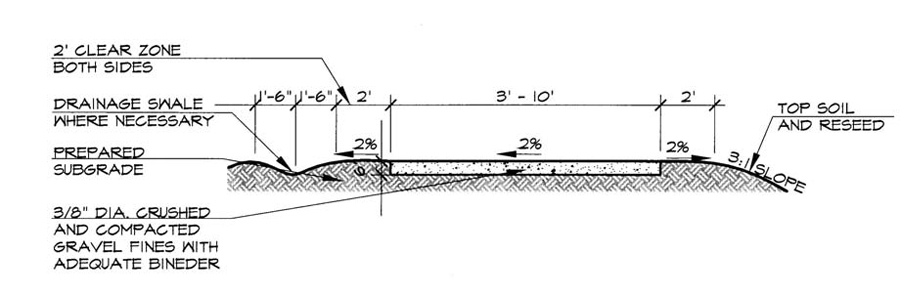
Figure 9. Typical Gravel Fines.
d.
Grade, sight distance, drainage. Refer to design objectives and standards for hard surface trails.
C.
Trail crossing structures. Where bridges and trailheads are shown on the Allen Trails Implementation Plan, the developer of the property on which those improvements are shown shall be required to construct those improvements and in accordance with the land development code. If a bridge is required, where the developer only owns one side of the creek or waterway to be crossed, the city may accept funds in escrow for one-half of the bridge or crossing.
1.
Pedestrian bridges.
a.
Trail crossings over creeks shall be by bridge (see subsection "b" for crossings over ravines and small streams). Pre-fabricated bridges require approval by the city. Bridges shall be of arched-truss design and shall be designed to comply with ADA criteria. The minimum width of any bridge shall be two feet wider than the widest trail connecting to the structure, e.g., a ten-foot wide trail shall be served by a 12-foot wide bridge.
b.
Design bridges that are sturdy, safe, vandal resistant and easily maintained:
i.
Deck shall be of iron wood/IPE wood.
ii.
The deck members shall be stabilized to minimize vibrations, and shall be fastened to the substructure at the outside edges and at a minimum of two intermediate stringers running the full length of the deck.
iii.
Railing shall be free of splinters and provide a smooth, clean surface to the touch.
iv.
Railing design shall allow views to creeks for persons of all heights, yet prevent anyone from falling through.
v.
Scale of bridge shall be in keeping with its surroundings.
vi.
Bridge color shall blend with the natural environment or relate to the color scheme of adjacent development.
vii.
Integrate design with other elements throughout the creek corridor.
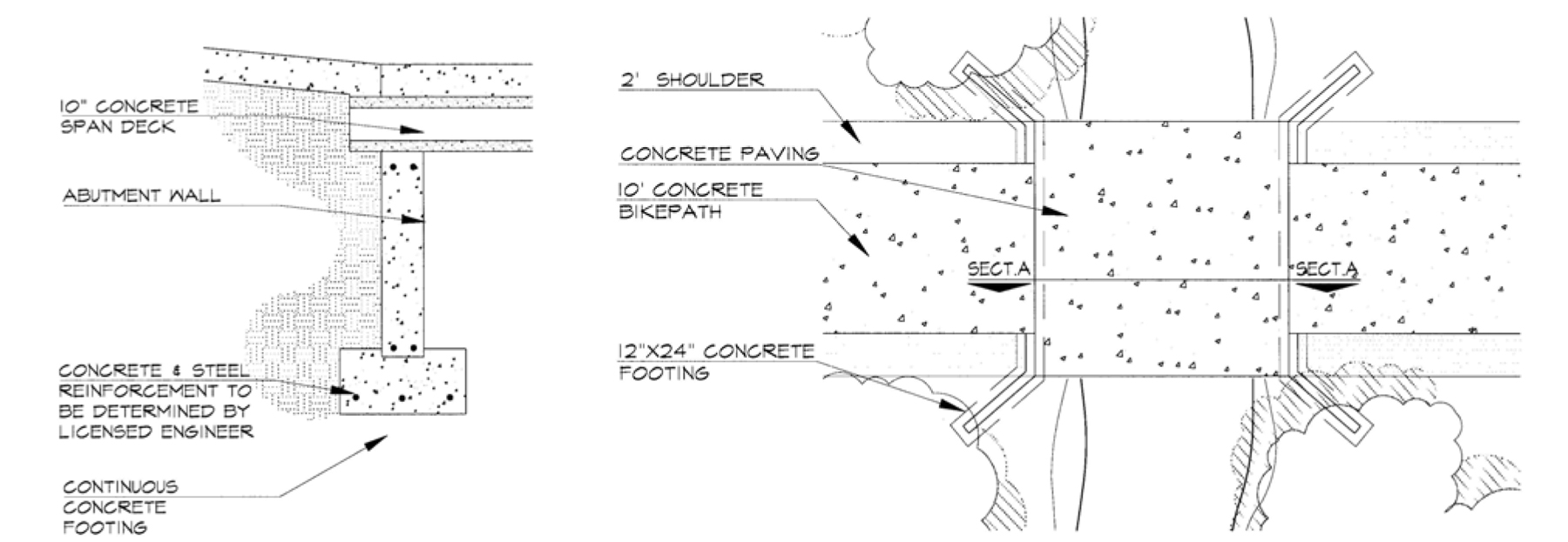
Figure 10. Low Water Crossing.
2.
Design standards.
a.
Refer to Figure 11 for typical bridge design and Figure 10 for low water crossings. All bridges and low water crossing designs to be sealed by a registered state professional engineer and approved by the city. Low water crossings shall not exceed three feet from path to flowline of the waterway or ravine. Any crossing exceeding this three-foot separation to permit the construction of ADA-compliant trail approaches to the crossing shall require a bridge.
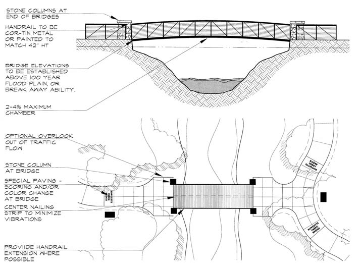
Figure 11. Typical Bridge Design.
[D.
Reserved.]
E.
Culvert outfall structures.
1.
Design objectives. Many existing culvert pipe structures may need modification to meet trail safety and aesthetic standards. Culvert outfalls shall occur on the downhill side of trails.
2.
Culvert crossings. Culvert crossings may be used at creek tributaries or ravines with the approval of the city. In all cases, the following shall apply:
a.
Culvert crossings shall be capable of supporting loads of city maintenance vehicles, and designs shall be sealed by a Texas professional engineer.
b.
There shall be no untrimmed metal or plastic culvert piping exposed at upstream and downstream faces of the structure.
c.
Culvert crossings shall have an upstream and downstream retaining wall supporting the trail, and shall be wide enough to accommodate the trail width plus a three feet shoulder on both sides of the trail width for the entire length of the crossing. The retaining wall shall be faced and capped with a veneer of mortared stone or a patterned concrete.
d.
All side slopes shall be fine-graded and protected with heavy-duty erosion control blanket, pinned per the manufacturer's recommendations.
e.
All crossings shall include safety railing, powder-coated with no exposed uncoated metal.
3.
Low water crossings.
a.
Low water crossings may be used only where the vertical distance from the trail surface elevation to the flow line of the waterway is three feet or less. In all situations, the decision to allow a low-water crossing in lieu of a culvert crossing will be made by city staff. Any crossing that exceeds this three-foot separation shall require a culvert crossing or a bridge.
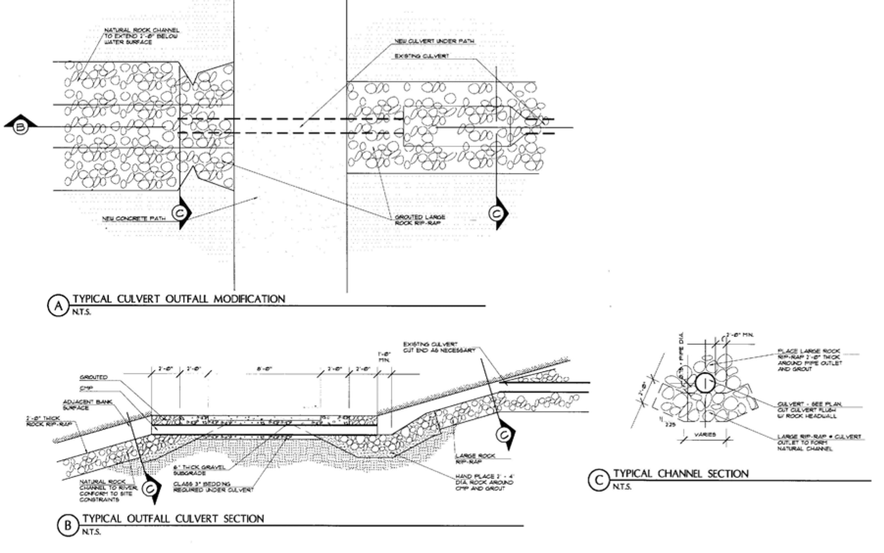
Figure 12.
F.
Underpass structures.
1.
Design objectives.
a.
Underpasses are key elements within the plan. These elements provide safety and continuity by eliminating the need for users to interact and/or cross busy streets.
2.
Design standards.
a.
Underpasses shall be constructed according to minimum vertical and horizontal clearances. All modified underpasses should meet these requirements. In situations where the underpass is straight (allowing clear visibility), two-way traffic can be accommodated. Underpasses under existing bridges shall conform to details on Figure 13.
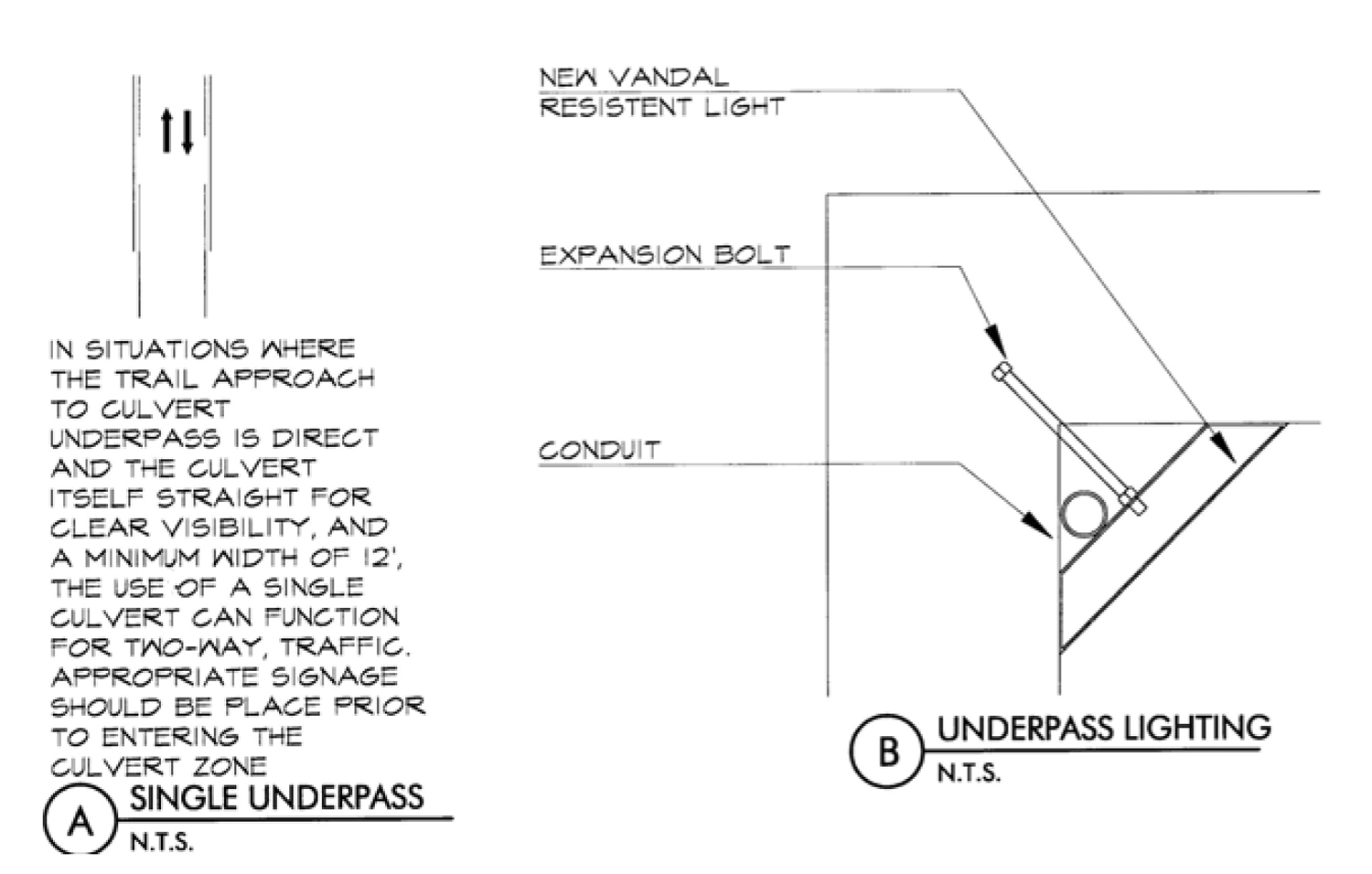
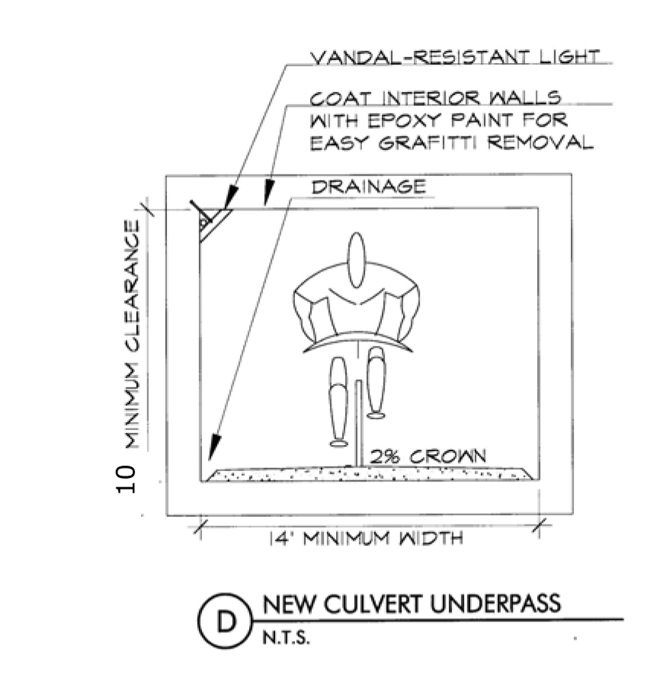
Figure 13. Culvert Underpasses.
G.
Bike path safety railing.
1.
Design objectives. Railings are required in situations where bicyclists or pedestrians may fall down an embankment or other vertical displacement. Railings, fences, or barriers on either side of a trail structure should extend 42 inches higher than the trail surface and should have smooth rub rails attached at handlebar height (3.5 feet) made of smooth metal or similar material. Railing ends shall be angled downwards and flared away from the trail at either end of the railing to prevent cyclists and pedestrians from catching on the railing.
2.
Design standards.
a.
Refer to Figure 14 for typical construction.
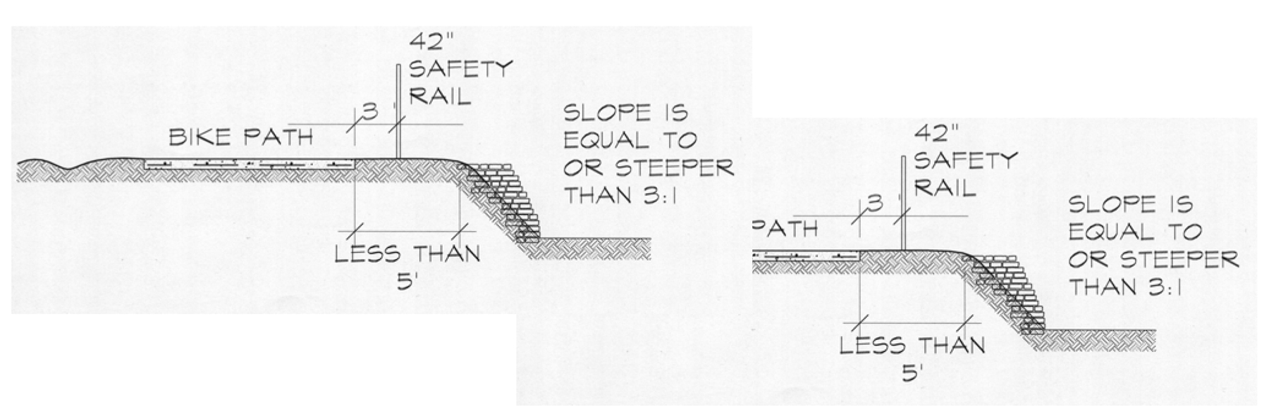
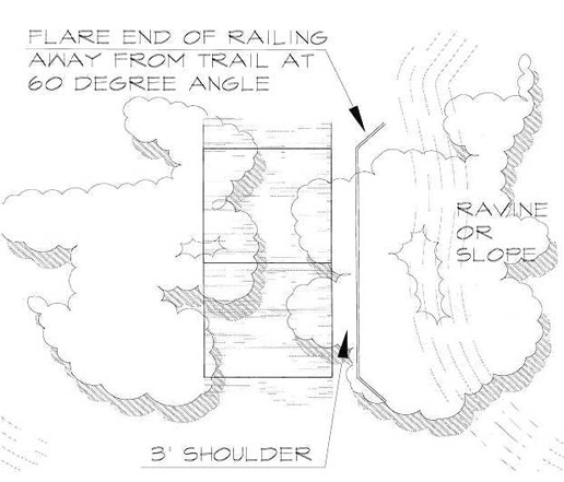
Figure 14. Safety Railing.
H.
Signed shared roadways (bike routes).
1.
Design objectives.
Provide through and direct travel in bicycle demand corridors.
Connect discontinuous segments of shared used paths, bike lanes, and or routes.
Provide a common route for bicyclists through a high demand corridor.
Provide extensions along local neighborhood streets and collectors that lead to commercial, employment, educational, parks and other community facilities.
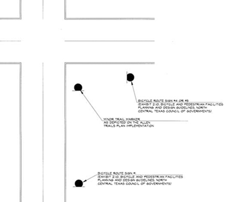
Figure 15a. Route Signage.
2.
Design standards.
Bike route signs may be used on streets with bike lanes, as well as on shared used paths.
Route signs should include destination information.
Minor trail signs shall be located at all intersections where the bike route changes direction.
Additional route signs should be located in accordance with AASHTO and MUTCD standards. (See Figure 15a.)
Adjust utility covers to grade, install bicycle safe drainage grates, and fill potholes to provide a smooth surface.
Curb lane widths generally meet or exceed a width of 14 feet.
I.
Trailheads.
1.
Design objectives.
Provide transition between motorized and nonmotorized transportation and recreational systems.
Create a unique entry to the consolidated trail system through hardscape and landscape aesthetics that support themes established within the Allen Streetscape Imagery Study.
Encourage utilization of trail and bicycle routes as alternative transportation paths within city.
Provide access to a variety of nodes, streets, and trails.
Utilize existing facilities such as schools, civic facilities (library, city hall, future DART stops), and parks as trailheads. Establish a hierarchy of trailheads ranging from major, primary, and secondary.
2.
Design standards. All schools, parks, and civic facilities are potential trailheads, as well as those areas indicating major, secondary and minor trail markers. Trailheads are divided into three types: Major, Primary and Secondary.
Major trailheads:
Trailheads shall provide a minimum 12 parking spaces and two handicap spaces. One parking space must be van accessible. Sidewalks shall connect handicap spaces to the trails and parking spaces shall be signed for trailhead usage.
Bike racks approved by the city shall be provided at a ratio of one bike space for every parking space. No less than five bike spaces shall be provided in a rack at any major trailhead.
One drinking fountain approved by the city shall be provided within 30 feet of benches and bike racks. Drinking fountains shall be ADA compliant and approved by the city. Drinking fountains must be plumbed to drain to the nearest storm sewer or to a below-ground sump approved by the city.
One bench approved by the city for every three parking spaces shall be provided, with minimum one bench provided.
Parking lots and trail intersections shall be lighted to a minimum of one-half footcandle with metal halide fixture and no spillover to adjacent property.
Trails which terminate at major trailheads shall receive landscape traffic control measures as indicated in the at-grade crossing section of these guidelines.
Trailheads shall provide one canopy tree per two parking spaces provided with minimum three trees provided.
Major trailheads shall be identified by major trail markers.
Primary trailheads:
Trailheads shall provide a minimum five spaces and one handicap space. One space must be van accessible. Sidewalks must connect handicap spaces to trail. Parking spaces shall be signed for trailhead usage.
Bike racks approved by the city must be provided at a ratio of one bike space for every one parking space, with not less than five bike spaces at any primary trailhead.
One drinking fountain approved by the city shall be provided within 30 feet of benches and bike racks. Drinking fountains shall be ADA compliant and approved by the city. Drinking fountains must be plumbed to drain to the nearest storm sewer or to a below-ground sump approved by the city.
One bench approved by the city for every three parking spaces shall be required with a minimum of one bench.
Parking lots and trail intersections shall be lighted to a minimum of one-half footcandle with metal halide fixture and no spillover to adjacent property.
Trails which terminate at major trailheads shall include landscape traffic control measures.
Trailheads require one canopy tree per two parking spaces provided with minimum three trees provided.
Primary trailheads shall be identified by major or secondary trail markers.

Figure 15b. Primary Trailhead.
Secondary trailheads:
Parking is not required at secondary trailheads.
One bike rack (four holding capacity) shall be provided at any secondary trailhead.
No drinking fountains need to be provided.
One bench approved by the city shall be provided.
Parking lots and trail intersections shall be lighted to a minimum of one-half footcandle with metal halide fixture and no spillover to adjacent property.
Trails which terminate at major trailheads shall include landscape traffic control measures.
Secondary trailheads shall have not less than three canopy trees and be identified by secondary trail markers.
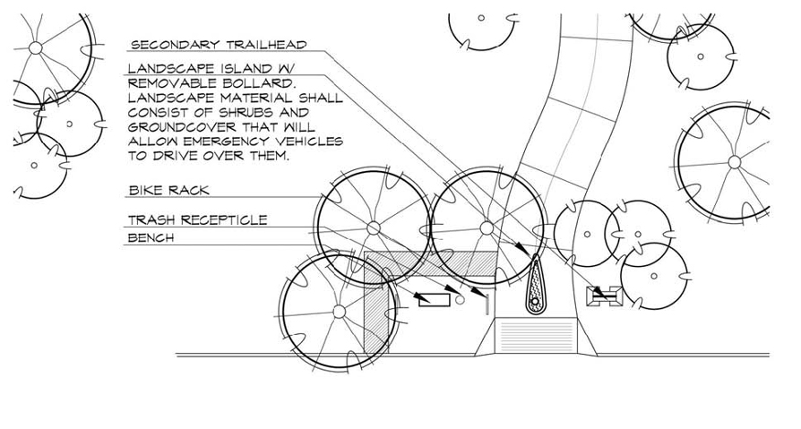
Figure 16. Secondary Trailhead.
3.
Related improvements.
a.
Lighting.
1.
Design objectives.
a.
Lighting for trails is important and should be considered where riding at night is expected. Fixed-source lighting reduces conflicts along paths and at intersections. In addition, lighting allows the cyclist to see the trail alignment, surface conditions, and obstacles. All trail intersections and the intersection of trails with public streets should be illuminated in such a way that cyclists and motorists have ample opportunity to see and react to the intersection. Lighting shall be provided throughout entire lengths of underpasses or tunnels. Lighting should also be provided wherever there is signage, particularly warning signs.
2.
Design standards.
a.
Lighting standards along public streets should meet or exceed those established by code. Parking lots and trail intersections shall be lighted to a minimum of one-half footcandle with metal halide fixture and no spillover to adjacent property, but parking areas should be sufficiently illuminated to meet security concerns. Approaches to intersections and trail underpasses shall be lit to provide one-half to one continuous, unbroken footcandle of illumination on the trail or path surface.
b.
Retaining walls.
1.
Design objectives. Retaining walls should be functionally efficient at the scale of the trail user and should:
Incorporate interest, texture, and detail in the design where feasible.
Be terraced if over four feet in height. Terraced walls may provide seating, viewing, and a separation of the path from adjacent development, etc. Walls that provide seating should be separated from the mainstream flow of traffic. Seating areas should be situated at points of visual interest.
2.
Design standards. Figure 17 shows typical construction. Seal of a Texas registered professional engineer required.
WALL DESIGN DIMENSIONS
J.
At-grade crossings.
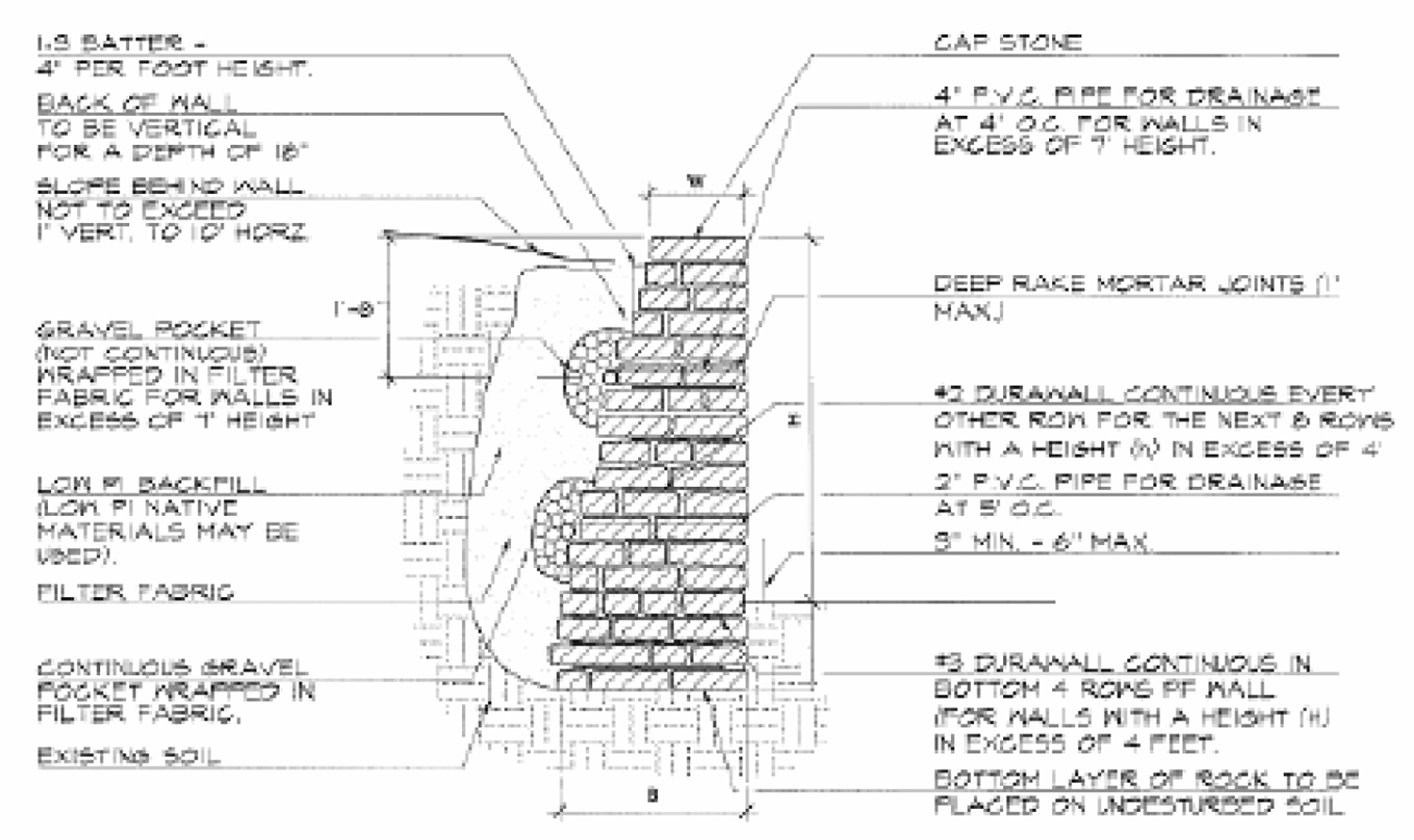
Figure 17. Retaining Walls.
1.
Design objectives.
Create aesthetically pleasing intersections that also provide protection for the trail user when crossing the street.
Coordinate at-grade crossings with Allen Thoroughfare Image Study to develop a cohesive intersection design.
Use landscaping to deter the access of motorized vehicles to the trail. The use of bollards is required where there are space constraints. (See Figure 17.)
2.
Design standards.
Comply with AASHTO standards regarding at-grade intersections.
Refer to Allen Thoroughfare Image Street Study to coordinate key intersection crossings.
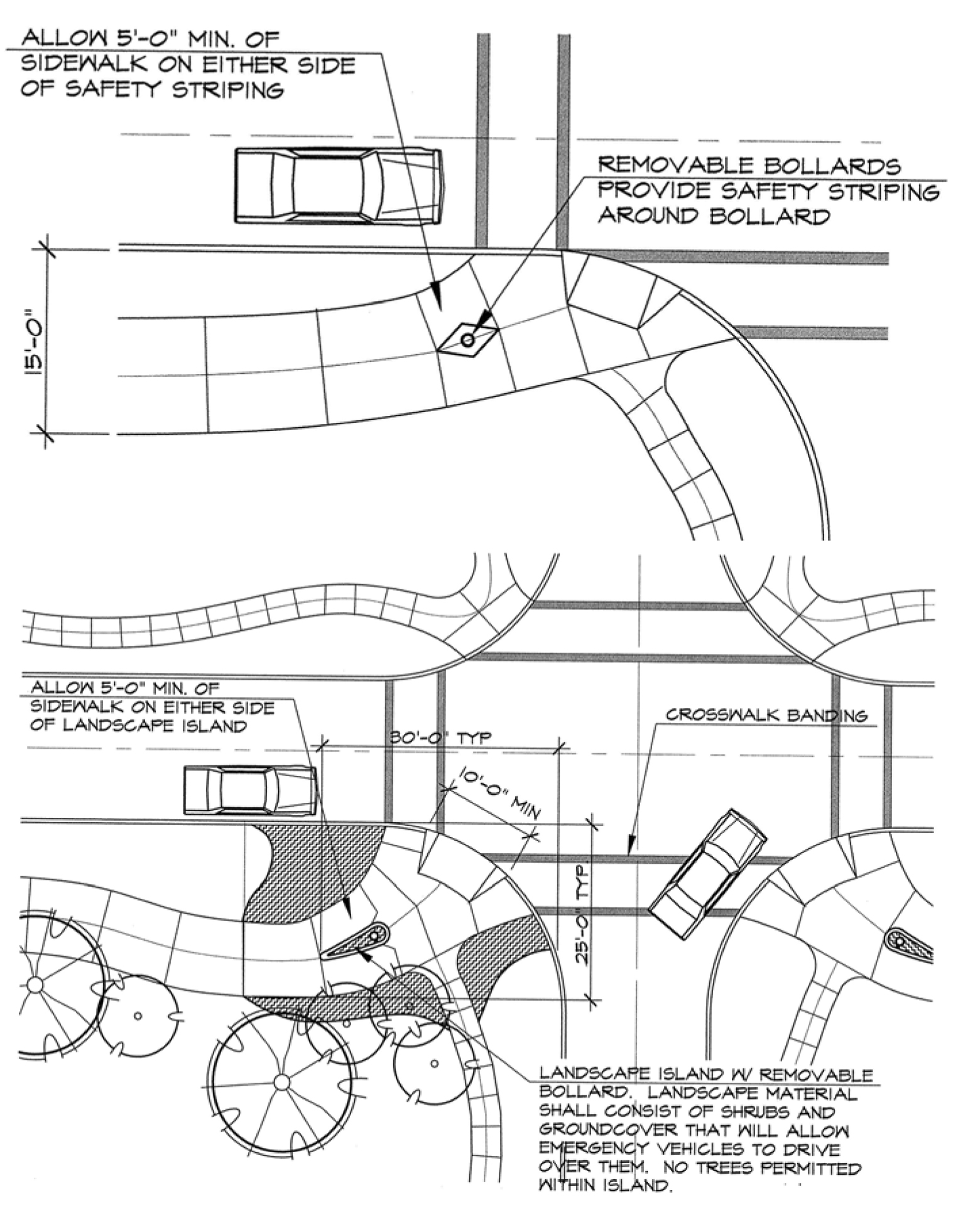
Figure 18. At-Grade Crossings.
(Ord. No. 2112-11-02, 11-26-2002; Ord. No. 2593-2-07, § 1(Exh. A), 2-13-2007; Ord. No. 2900-3-10, § 19.A—19.C, 3-23-2010)