
Colleyville City Zoning Code
CHAPTER 14
- ENGINEERING DESIGN STANDARDS
Sec 14.100 - Purpose of this chapter.
The purpose of this Chapter is to establish minimum standards and construction details for all public facility improvements.
Sec 14.105 - Authorization for adoption of this chapter.
The regulations contained in this Chapter have been adopted under the following authority:
A.
Chapter 212, Municipal Regulation of Subdivisions and Property Development of the Texas Local Government Code, which authorizes a municipality to adopt rules governing plats and subdivisions of land within the municipality's jurisdiction.
B.
Chapter 51, General Powers of Municipalities of the Texas Local Government Code, which authorizes a municipality to adopt ordinances, rules, or police regulations that are for the good government, peace, or the trade and commerce of the municipality.
C.
The Home Rule Charter of the City of Colleyville, which authorizes the City Council to exercise all powers granted to municipalities by the Constitution or the laws of the State of Texas.
Sec 14.110 - Applicability of this chapter.
The provisions of this Chapter shall be applicable to all public improvements owned and maintained by the City of Colleyville and to any semi-public improvements owned and maintained by a property owner's association that are intended to serve and function as a public improvement.
Sec 14.115 - Variances and appeals.
A.
The Director of Public Works may consider an alternative proposal of a regulation contained in this Chapter in order to achieve the best overall design. When considering such a proposal, the Director of Public Works shall determine that the approval, disapproval or modification will not be detrimental to the public safety, health, or welfare or injurious to other property and is consistent with sound engineering practices. The applicant shall provide information to support a claim that the public interest may be better served by an alternative proposal.
B.
Any person seeking approval of a development may appeal a decision of the Director of Public Works regarding the regulations contained in this Chapter by using the procedures described in Chapter 1, General Provisions of this Land Development Code.
Sec 14.120 - General conditions.
A.
"COG" and "TXDOT" Specifications. All drawings and details contained in Chapter 15 - Public Works Construction Details which include references to "item numbers", "specs" and "types" shall be governed by the latest version of "Standard Specifications for Public Works Construction, North Central Texas" of the North Central Texas Council of Governments ("COG"), with all amendments thereto, and shall constitute the technical specifications, except as amended by this Land Development Code, and made a part thereof, but not physically bound within this document. Streets shall be designed in accordance with the most current edition of The Texas Department of Transportation's Highway Design Division Operations and Procedures Manual, AASHTO's A Policy on Geometric Design of Highways and Streets, and the Transportation Research Board's Highway Capacity Manual.
B.
Acceptance of Improvements. No public improvements shall be accepted by the City or its representatives, unless and until such improvements conform to this Land Development Code and all other applicable standards as prescribed by the City of Colleyville. All streets, alleys, sidewalks, drainage-ways, signage, water and sewer lines and all other public improvements shall be designed, placed and constructed in accordance with the design criteria contained in this Land Development Code.
C.
Plan Review and Inspection Fees. Prior to the acceptance by the City of any public improvements, the developer shall pay the City a plan review fee and an inspection fee as follows:
1.
Engineering Plan Review Fee: 2% of the actual cost of the public improvements
2.
Engineering Inspection Fee: 3% of the actual cost of the public improvements
D.
City-Developer Agreements.
1.
Requirement: When it is proposed that the City will share in the costs with a developer for the construction of public improvements, no public improvements shall be constructed within a development, unless and until a City-Developer Agreement has been approved by the City Council. Where the public improvements are a requirement of a subdivision plat approval, the City-Developer Agreement shall be submitted to the City Council for approval at the same time as the plat submittal, or as soon thereafter as practical.
2.
City Participation: The City may share in the costs with a developer for constructing public improvements relating to a development, provided a City-Developer Agreement has been approved by the City Council in accordance with this Section. The limits of City participation shall be expressly established in the agreement at a level not to exceed thirty (30) percent of the total contract price. Under the agreement, the developer shall construct the public improvements and the City shall participate in the costs. Where a developer is requesting City participation in the construction of a public facility and the total participation cost by the City exceeds twenty-five thousand ($25,000) dollars, the procurement procedures specified in the Texas Local Government Code for public improvements shall be used by the developer. All records to the developer's cost of constructing the public improvements shall be maintained and made available for inspection by the City.
3.
Construction Plans: It shall be the responsibility of the developer's engineer to prepare all engineering construction plans and contract documents for construction of the project for the use of the City and the contractor.
4.
Performance Bond: Where a City-Developer Agreement has been authorized, the developer shall execute a performance bond for the construction of the public improvements which shall include any City participation to ensure their completion.
5.
Authorization to Proceed: On projects not requiring a City-Developer Agreement, the developer may proceed with the construction of the public improvements after the City has issued a letter authorizing the developer to proceed with the construction, provided the engineering construction plans have been approved by the Director of Public Works. All construction shall be in accordance with the applicable sections of this Land Development Code. The developer may select his own contractor subject to the contractor executing the necessary bonds with the City and payment of the inspection fees required for each portion of the public facilities.
Sec 14.125 - Construction plan requirements.
The purpose of this Section is to specify the minimum construction drawing requirements for all public improvement projects, including public improvements associated with a proposed subdivision or commercial development. All construction plans for public water, sanitary sewer, street, drainage and traffic improvements shall be designed, signed, sealed, and dated by a Registered Professional Engineer licensed in the State of Texas. All construction plans or drawings must be accompanied by a Geotech Report signed, sealed, and dated by a Registered Professional Engineer licensed in the State of Texas. Plans and drawings shall adhere to the requirements in this Section and be furnished in the format listed herein:
A.
General Requirement. No construction of any public improvement shall commence, unless and until the construction plans for the proposed public improvement has been approved by the Director of Public Works or designee.
B.
Number of Copies. The developer, or developer's engineer, shall submit the minimum number of copies required by the Director of Public Works to distribute to the various City departments to adequately review the proposed improvements.
C.
Cover Sheet.
1.
Project title.
2.
Property legal description, if applicable.
3.
City name.
4.
Vicinity map.
5.
Owner, engineer, and surveyor name, address and telephone number.
6.
Project title in small print placed vertically along the right border.
7.
Sheet index.
8.
Signature block for City approval.
D.
Copy of Current Plat. When construction plans are related to a new subdivision or a commercial development, a copy of the current plat shall be bound with the construction plans. The signed plat shall be bound with the as-built drawings.
E.
Drainage Area Map. The drainage area map is critical to all drainage designs, since the ultimate layout, sizing and hydraulic analysis is dependent upon a thorough review of the proposed development. This map should be accompanied with all drainage calculations. The Drainage Area Map must show the physical features of the site that either exist or are proposed, including the existing and proposed contours, existing and proposed storm sewers, and/or other drainage facilities. Commercial projects should include the locations of buildings, flatwork and pavement.
F.
Site Plan. The developer of a commercial project shall submit a site plan indicating the location and width of all proposed and existing street and driveway approaches noting the back-of-curb radii.
G.
Utility Plan. This drawing shall indicate the location and size of all existing and proposed water and sanitary sewer lines with adjacent existing or proposed top of curb grades. Show the location of all existing and proposed fire hydrants adjacent to the site including the maximum coverage radius of each as outlined in later sections of this manual.
H.
Plan and Profile Sheets. Plan and profile drawings shall be required for roads, sewers, storm sewers, channels, flumes, and water lines twelve (12") inches in diameter and larger. Stationing shall be generally left to right and with stationing beginning at the downstream end for all sewers, storm sewers, and channels. Stationing shall be included on the plan view as well as the profile for all roads, water, sewer, storm sewer and channel sheets. Elevations shall be calculated and provided on all profiles as indicated below.
1.
Straight grade: Provide elevations at a maximum interval of 50 feet.
2.
Vertical curve: Provide elevations at the beginning and ending points and at a maximum interval of 25 feet in between.
I.
Plan and Profile Sheet Size. Plan and profile sheets shall not exceed twenty-four (24") inches wide by thirty-six (36") inches long. Horizontal scale shall be one (1") inch equals fifty (50') feet or larger, i.e. 1" = 40'. Vertical scale shall be one (1") inch equals five (5') feet or larger.
J.
Details. Drawing details shall be included with all construction plans to clarify proposed construction specifications and said details shall be consistent with Chapter 15 of this Land Development Code.
K.
Plotting Drainage Features. Appropriate hydraulic grade line or water surface profile shall be plotted with all drainage designs. Capacity, design discharge, velocity, and velocity head shall be noted on each segment of a drainage facility in the profile whenever one or more of these parameters changes.
L.
Erosion Control Plan. The developer of a subdivision or a commercial project shall submit an erosion control plan in accordance with the requirements of Chapter 12, Erosion Control.
M.
Stormwater Pollution Prevention Plan. The developer of a subdivision or a commercial project shall submit a stormwater pollution prevention plan in accordance with the requirements of the Texas Commission on Environmental Quality.
N.
Street Sign Plan. showing the location of all proposed street name signs and traffic control signs. The street sign plan shall include an elevation view of each street sign indicating the type and color of each sign. All signs shall comply with the requirements of the latest edition of the Texas Manual on Uniform Traffic Control Devices. Refer to street sign standards, located elsewhere in this Land Development Code (Section 14.145).
O.
City Review and Approval Process. All construction plans for public improvements shall be reviewed by city staff for compliance with this Section and with any applicable guidelines of other agencies. City staff shall provide written comments to the developer and the developer shall respond to all city comments. The Director of Public Works, or designee, shall not approve any construction plans until all comments have been resolved and the construction plans determined to be acceptable to the city. All approved construction plans shall be signed by the Director of Public Works, or designee, and no construction work shall commence until a pre-construction meeting has been held and a letter of authorization to proceed has been issued by the Director of Public Works. Development projects which have not started within one year from the date of approval of the construction plans shall require a new review.
(O-00-1261, 12-19-00)
Sec 14.130 - Street design criteria.
A.
Right-of-Way Widths. The right-of-way widths for any proposed street shall be designed for the intended use and anticipated traffic volume at optimum development of the area served. Additional right-of-way may be required at street intersections and to provide for left and right turn lanes at high-volume intersections. The following table shall be used as a guide in determining right-of-way widths.
(1)
Street classification refers to the functional classification shown on the Master Thoroughfare Plan.
(2)
A local street having a total length in excess of one thousand two hundred (1,200) feet or serving more than thirty (30) dwelling units may be required to provide a right-of-way width of not less than sixty (60) feet.
(3)
A cul-de-sac street exceeding 600 feet in length shall have a 56' right-of-way and 36' of pavement.
B.
Design Speed and Maximum Grade. All streets shall be designed to conform to the following parameters:
(1)
The Director of Public Works may approve an alternate design.
Sec 14.135 - Driveway spacing and design standards.
A.
Residential Construction. Residential driveway approaches shall be constructed of six-inch thick three thousand five hundred (3,500) p.s.i. compressive strength concrete reinforced with #3 steel bars on 18-inch centers each way, with #4 bars doweled into the existing concrete paving.. Residential driveways shall be constructed with the return curbs having a rolled face disappearing at the sidewalk and joining the street curb.
B.
Commercial and Industrial Construction. Commercial and industrial driveway approaches shall be constructed of six-inch thick three thousand five hundred (3,500) p.s.i. compressive strength concrete reinforced with #4 steel bars on 18-inch centers each way, with #4 bars doweled into the existing concrete paving. Commercial and industrial driveways shall be constructed with the return curbs having a rolled face disappearing at the sidewalk and joining the street curb.
C.
Driveway Approach Depth. The driveway shall begin at the street curb and extend to the property line or to a point nine and one-half (9.5) feet from the back of the curb, whichever is greater. The drive approach shall be constructed such that the height of the drive approach at the property ROW, with a typical 9.5-foot parkway, shall be two and one-half (2½") inches higher than the top of the curb. The tangency point of a driveway curb shall be a minimum of ten (10') feet from a storm water inlet.
D.
Driveway Approach Widths and Spacing. The criteria contained in the following table shall be the minimum and/or maximum standards to be applied in spacing and designing driveways on public streets. For the purpose of this regulation, driveway width shall be measured at the property line. The Director of Public Works may modify these standards based on anticipated traffic flow and in accordance with sound traffic engineering practices. To implement the standards contained in the following table, subdivision plats for new commercial developments shall be required to provide cross-access easements.
E.
Provision for Joint Approaches. Driveway approaches shall be located entirely within the frontage of the premises they serve except that joint, or cooperative, driveways with adjoining property holders may be permitted by the Director of Public Works. When a joint drive approach is proposed by a developer, the request must be made by all interested parties and/or all property owners involved.
F.
Circular Driveway Approaches at Street Intersections. The Director of Public Works may approve a circular drive on a corner lot where both streets are residentially classified.
G.
Angle of Driveway Approach. The angle of the driveway approach with the curb line shall be ninety (90) degrees.
H.
Sidewalk to be Removed. Where a driveway approach is to be built, any existing sidewalk located within the proposed driveway location shall be removed and the entire area replaced as a driveway. The drive approach shall extend to the property line.
I.
Driveways Crossing Bar Ditches.
1.
Culvert Size: The minimum culvert pipe size shall be 18" diameter. However, an engineered design that provides for a larger culvert pipe size may be required by the developer where the Director of Public Works determines that additional drainage capacity may be required. The ends of all culvert pipes shall be cut at a 6:1 slope.
2.
Radius: Driveways shall be constructed with the return curbs joining the edge of pavement at the street with a minimum ten-foot radius.
3.
Slope: The maximum slope from the edge of driveway to the top of the culvert pipe shall be 6:1. The sloped area around the end of the culvert pipe shall be sodded or hydro-mulched to resist erosion.
4.
Cross Slope: The minimum cross slope on the drive shall be ⅛ inch per foot. The minimum longitudinal slope between the edge of pavement at the street and the valley over the culvert pipe shall be ¼ inch per foot.
5.
Maintenance: Future maintenance of the drive approach and culvert pipe is the responsibility of the property owner.
6.
Grading: During the drive approach installation, all ditch grading upstream and downstream of the proposed driveway culvert is the responsibility of the property owner.
j.
Driveway Access to Street Right-of-Way and Street Stub-Outs from Adjacent Subdivisions. Driveway access from a platted lot shall not be allowed onto a public street, stub-out or other public right-of-way located in an adjacent subdivisions unless a variance is approved by the City Council in conformance with the procedures set forth in Chapter 1 of this Land Development Code. Any variance from the provisions of this subsection shall, in addition to all other relevant information, take into consideration the following special considerations:
•
Impact to traffic on local residential streets from adjacent subdivisions.
•
Potential conflict between HOA covenants governing the use and maintenance of local subdivision streets and connecting subdivisions.
•
Potential impact on future subdivision design of adjacent subdivisions.
K.
General.
1.
Driveway Approaches at Pedestrian Crossings: Driveway approaches shall not be located in street intersections or at established pedestrian crossings.
2.
Driveway Approaches at Obstructions: Driveways shall be kept at a minimum of five (5) feet away from obstructions such as street light posts, fire hydrants, traffic signals, etc.
3.
Accumulative Width of Approaches: Driveway approaches shall not occupy more than forty (40) percent of the frontage of a lot or tract.
(Ord. No. O-23-2237, § 2(Exh. B), 3-21-23)
Sec 14.137 - Fire lane requirements (current city-adopted IFC).
A.
Plan Approval. Plans for fire lanes shall be submitted to the Fire Marshal Division for review and approval prior to construction. Repainting of existing markings does not require plan review unless changes are to be made.
B.
Obstructions Prohibited. Fire lanes shall be kept clear and unobstructed at all times. Marking shall be repainted as necessary to maintain readability.
C.
Signage. Where required by the Fire Marshal, approved signs or other approved notices shall be provided and maintained to identify fire lanes and prohibit obstructions.
D.
Where Required. Fire lanes shall be provided when any portion of the facility or any portion of an exterior wall of the first story of the building is located more than 150 feet from fire apparatus access as measured by an approved route around the exterior of the building or facility.
E.
Certain Roadways Not Considered Access. Heavily traveled public roadways are not considered for fire apparatus access due to the dangers involved with operating fire apparatus in close proximity to moving traffic.
F.
Access to Serve All Buildings. Fire lanes shall be provided to serve all buildings through parking areas to service entrances, loading areas, trash collection areas, and other areas deemed necessary to be available to fire and emergency vehicles.
G.
Driveways Included. Fire lanes shall include driveways leading onto a public street.
H.
Fire Lane Width. Fire lanes shall have an unobstructed width of not less than twenty-four (24) feet and an unobstructed vertical clearance of not less than fourteen (14) feet.
I.
Turning Radius. Fire lanes shall have a minimum inside turning radius of thirty (30) feet and a minimum outside turning radius of fifty (50) feet.
J.
All-weather Surface Required. Fire lanes shall be designed and maintained to support the imposed loads of fire apparatus and shall be provided with an asphalt or concrete surface so as to provide all-weather driving capabilities.
K.
Construction Specifications. Fire lanes shall be constructed of seven-inch concrete with #3 rebar on eighteen-inch centers on chairs over a modified subgrade as per the Geotechnical Soils Report; or seven-inch asphalt over a modified subgrade as per the Geotechnical Soils Report. The construction shall be capable of supporting a minimum of seven thousand five hundred (75,000) pounds gross vehicle weight.
L.
Maximum Dead-end Length. Dead end fire lanes in excess of one hundred fifty (150) feet in length shall be provided with an approved area for turning around fire apparatus. Dead end fire lanes more than one hundred fifty (150) feet in length but less than seven hundred (700) feet in length shall provide one of the following turn-around configurations. Dead end fire lanes in excess of seven hundred (700) feet in length shall be submitted to the Fire Marshal for review and approval.
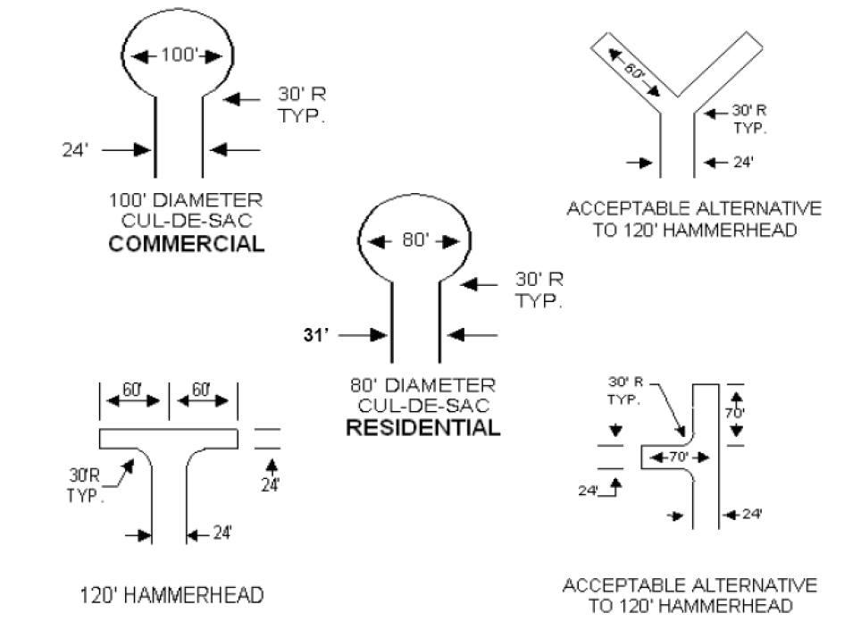
Note: In residential subdivisions where a proposed cul-de-sac will include an obstruction within its center, such as a planter or other impassable object, the pavement width shall measure a minimum of 100 feet.
M.
Fire Lane Striping. Fire lanes shall be marked with a six-inch wide continuous bright red stripe on both sides. Striping shall be on the curb face where curbing is located at the edge of fire lanes. White 4-inch high lettering with a one-inch stroke centered on red stripe shall read: NO PARKING - FIRE LANE. This lettering shall be painted every (15) feet measured from the end of one lettering group to the beginning of the next group with a one-foot space between "No Parking" and "Fire Lane". Red paint shall not be used for any parking lot marking other than fire lanes. Fire lane markings are subject to the field inspection of the Fire Marshal.
(Ord. No. O-09-1712, 3-3-09)
Sec 14.138 - Emergency access gates.
A.
Scope and Applicability. The regulations in this section shall be applicable to all gates or barriers that are permanently installed across an emergency access easement to a development for purposes of controlling, limiting, or prohibiting vehicular public access to a development.
B.
Definitions. For purpose of this regulation, an emergency access gate shall mean a gate mechanism which is used to allow access for emergency service vehicles or to allow public access during an emergency situation where the primary access to a development is not accessible or is determined un-accessible by the Fire Department.
C.
Permit. Approval of a permit issued by the fire department shall be obtained prior to the installation of an emergency access gate. Fire department staff shall coordinate the approval review process with other departments, as appropriate.
1.
Application: Application for an emergency access gate shall be submitted on forms furnished by the fire department, and include, at a minimum, the name and contact information of the gate contractor, and the name and contact information of the party responsible for the gate maintenance. The application shall be accompanied by drawings of the proposed gate improvements as outlined in this section.
2.
Construction Plan Requirements:
a.
For New Developments: Drawings showing the location and design of the proposed emergency access gates shall be included with the construction plans for the development. In the absence of any construction plans for the development, separate drawings showing the location and design of the proposed emergency access gates shall be submitted with the application.
b.
For Existing Developments: Drawings showing the location and design of the proposed emergency access gates shall be submitted with the application.
c.
Sufficiency of Drawings: Plans and drawings shall be clear and contain sufficient information and detail to determine conformance with these regulations.
d.
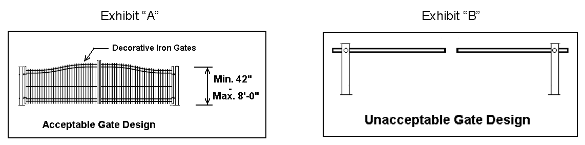
Design: The design of all gates, supporting members and access control devices, including automatic opening systems and manual backup systems, shall meet City guidelines or policies, be compatible with City transmitting equipment, and be approved by the City prior to installation. All gates shall be designed and constructed with materials that are comparable to the subdivision perimeter fencing of the applicable development, but shall not be a lesser design standard than shown on Exhibit "A". Lift arm gates or gates of similar design as shown in Exhibit "B" shall be prohibited on new gate installations.
e.
Encroachment Agreement: An emergency access gate proposed for installation within a public right-of-way shall require the approval of the City Council of a Right-of-Way Encroachment Agreement.
3.
Inspection: Upon completion of the installation of the emergency access gates, the Fire Department shall inspect the gates for conformance to these regulations and any other applicable codes and ordinances. All emergency access gates, cross arms and opening devices shall be tested and approved by the City prior to being put into operation.
D.
Requirements. All new emergency access gates shall comply with the following minimum requirements:
1.
When in the open position, an emergency access gate shall provide an unobstructed opening of twenty-four (24) feet wide and fourteen (14) feet high.
2.
Swinging gates for single direction traffic shall swing in the direction of vehicle travel.
3.
Swinging gates for bi-directional traffic shall swing into the property being entered.
4.
Emergency access gates shall be installed within the limits of the emergency access easement, unless an alternate location is determined acceptable by the fire department. If located within a public right-of-way, approval by the City Council of a Right-of-Way Encroachment Agreement is required.
5.
Gates shall not be installed within a required turning radius of a fire access roadway.
6.
An emergency access gate shall be electrically operated for entry and exit by an approved emitter system (Opticom®) that is compatible with fire department traffic signal pre-emption equipment. The receiver equipment shall have Knox® Key over-ride and a power failure mechanism.
7.
No parking shall be permitted within the emergency access easement or near the emergency gates.
E.
Pedestrian Access. A development containing an emergency access gate shall provide for a separate pedestrian access gate within 10 feet of the vehicle gate.
F.
Maintenance. Emergency access gates shall be maintained in good working order by the property owners of the development receiving benefit from the gates. Gate maintenance shall include lubrication of moving parts and hinges, batteries required for operation of the system during power failure, and any electrical and mechanical equipment required for the proper operation of the automatic gate opening system. The City of Colleyville reserves the right to inspect an emergency access gate at any time and require the party responsible for the maintenance of the gates to provide the repairs necessary to ensure emergency access. The City of Colleyville assumes no responsibility for the construction or maintenance of an emergency access gate.
G.
Failure to Maintain. If the property owners of a development or the homeowners association fail to maintain reliable access, the City shall have the right to enter the development and remove any gate or device which is a barrier to emergency access at the sole expense of the property owners. The gate permit may be revoked and the gate locked in the open position for any cause determined by the fire department to be in the best interest of public safety.
(Ord. No. O-07-1613, 3-20-07)
Sec 14.140 - Street improvement specifications.
A.
General. Streets shall be constructed or reconstructed using either hot-mixed asphaltic concrete pavement sections or reinforced Portland cement concrete pavement sections that meet or exceed the minimum specifications of this Land Development Code. The developer requiring street construction shall provide a geotechnical report, sealed by a Registered Professional Engineer licensed in the State of Texas, containing recommendations for subgrade thickness and content. The minimum subgrade and pavement thickness shall be in accordance with the specifications contained in this Section.
For the purpose of this Section, a collector street shall be defined as all those collector streets shown on the Master Thoroughfare Plan and those streets internal to a subdivision which provide connection between local residential streets and the major collector network and which are designed to accommodate more than 500 vehicles per day.
B.
Hot-Mixed Asphaltic Concrete Pavement Sections.
1.
Local Streets (including cul-de-sac):
a.
Eight (8") inches thick (minimum) stabilized subgrade, twelve (12") inches past the back of curb line.
b.
Prime (or cure) coat.
c.
Five (5") inches Type "A" or "B" hot-mixed asphaltic concrete placed in three (3) lifts. The bottom lift shall extend to one (1') foot beyond the back of curb line.
d.
Two (2") inches Type "D" hot-mixed asphaltic concrete placed in one (1) lift.
2.
Collector Streets:
a.
Eight (8") inches thick (minimum) stabilized subgrade, twelve (12") inches past the back of curb line.
b.
Prime (or cure) coat.
c.
Six (6") inches Type "A" or "B" hot-mixed asphaltic concrete placed in three (3) lifts. The bottom lift shall extend to one (1') foot beyond the back of curb line.
d.
Two (2") inches Type "D" hot-mixed asphaltic concrete placed in one (1) lift.
3.
Arterial Streets:
a.
Eight (8") inches thick (minimum) stabilized subgrade, twelve (12") inches past the back of curb line.
b.
Prime (or cure) coat.
c.
Eight (8") inches Type "A" or "B" hot-mixed asphaltic concrete placed in four (4) lifts. The bottom two lifts shall extend to one (1') foot beyond the back of curb line.
d.
Two (2") inches Type "D" hot-mixed asphaltic concrete placed in one (1) lift.
4.
Stabilized Subgrade for Hot-Mixed Asphaltic Concrete Pavements: The basic design of the asphaltic pavement sections for streets and roads assumes average subgrade conditions which in all cases shall be stabilized to not less than the thickness shown herein with lime or cement at a minimum rate of 6% of the necessary volume or that recommended by an approved and acceptable geotechnical report submitted to the City by a licensed Geotech Engineer. Classification of the subgrade for evaluating the supporting qualities shall generally apply to the top 12-inch layer of soil measured down from subgrade surface. Where combinations of conditions indicate special problems, such as springs or seepage, drastic material changes from point to point, etc., that reduce the existing subgrade below average, appropriate remedies designed by a Registered Professional Engineer based upon actual onsite observations and tests shall be included to correct the particular condition involved. In all cases, the requirements set forth in this criteria are minimum and the City reserves the right to require further additional testing (such as California Bearing Ratio), precautions or treatments consistent with sound engineering practice when necessary to provide for other conditions not specifically covered by this criteria. Compaction of stabilized subgrade shall be 95% standard proctor density.
C.
Reinforced Portland Cement Concrete Pavement Sections.
1.
Local Streets (including cul-de-sac):
a.
Six-inch thick stabilized subgrade, twelve (12") inches past the back of curb line.
b.
Prime (or cure) coat.
c.
Six-inch thick Portland cement concrete, reinforced with #3 reinforcing bars having a spacing of eighteen (18") inches center to center both ways.
2.
Collector Streets:
a.
Six-inch thick stabilized subgrade, twelve (12") inches past the back of curb line.
b.
Prime (or cure) coat.
c.
Seven-inch thick Portland cement concrete, reinforced with #4 reinforcing bars having a spacing of eighteen (18") inches center to center both ways.
3.
Arterial Streets:
a.
Six-inch thick stabilized subgrade, twelve (12") inches past the back of curb line.
b.
Prime (or cure) coat.
c.
Eight-inch thick Portland cement concrete, reinforced with #4 reinforcing bars having a spacing of eighteen (18") inches center to center both ways.
4.
Basic Requirements For All Reinforced Concrete Pavement: The basic design of reinforced concrete pavement sections for streets and roads assumes poor subgrade conditions which shall be stabilized with lime or cement at a minimum rate of 6% of the necessary volume or that recommended by an approved and acceptable geotechnical report submitted to the City by a licensed Geotech Engineer. In all cases, the requirements set forth in this criteria are minimum and the City reserves the right to require further additional testing (such as California Bearing Ratio), precautions or treatments, when necessary, consistent with sound engineering practice to provide for other conditions not specifically covered by this criteria.
5.
Concrete for Pavement: Concrete for pavements shall be Class "A" and consist of five (5) sacks (minimum) of Portland cement for each cubic yard of concrete mix and have a seven-day flexural strength of five hundred pounds per square inch (500 p.s.i.) and a 28-day compressive strength of three thousand five hundred pounds per square inch (3,500 p.s.i.). Composition and placement of reinforced concrete pavements shall be in accordance with the applicable requirements of Item 360 of the Texas State Department of Transportation Standard Specifications. Coarse aggregate shall be either number 2 or 3. Cement for the mixture shall be Type I Portland cement. All hand pours are to be six (6) sacks minimum of Portland cement for each cubic yard of concrete mix with a compressive strength of three thousand five hundred pounds per square inch (3,500 p.s.i.).
D.
Curb and Gutter Specifications. All streets shall be provided with reinforced Portland cement concrete curbs and gutters in accordance with the following specifications.
1.
Curbs and gutters:
a.
Curb rolls shall be six (6") inches wide and not less than six (6") inches high nor more than seven (7") inches high.
b.
Curb and gutter bases shall not be less than twenty-four (24") inches wide and provide a minimum gutter width of eighteen (18") inches (see detail P-4A and P-4B).
c.
Gutter depths for hot-mixed asphaltic concrete pavement shall be five (5") inches for local streets and six (6") inches for collector and arterial streets. Gutter depths for reinforced Portland cement concrete pavement shall be the same as the pavement thickness.
2.
Reinforcement Steel: Reinforcement shall be provided by three (3) #3 steel reinforcing bars by placing one (1) bar in the curb roll and two (2) bars in the curb and gutter base. This reinforcement is in addition to reinforcement in Portland cement concrete pavements.
3.
Concrete Classification: Concrete for curbs and gutters shall be Class "A" and consist of five (5) sacks (minimum) of Portland cement for each cubic yard of concrete mix and have a seven (7) day flexural strength of five hundred pounds per square inch (500 p.s.i.) and a twenty-eight (28) day compressive strength of three thousand five hundred pounds per square inch (3,500 p.s.i.).
4.
Installation Procedure: Curb and gutter for hot-mixed asphaltic concrete pavements shall be placed on the first two-inch lift of asphaltic paving. For reinforced Portland cement concrete pavements, the curb and gutter base shall be placed monolithically with the pavement. The curb roll shall be placed monolithically with the pavement or added separately. Curb rolls added separately shall be provided with #3 reinforcing bar stirrups spaced twenty-four (24) inches center to center which extend to within three (3) inches of the bottom of the pavement.
5.
Driveway Cuts: All driveway entrances constructed in existing curb and gutters shall be saw-cut at the curb return on both sides of the driveway and eighteen (18") inches into the street. After work is completed, the street sidewalk shall be repaired and it shall be the responsibility of the party installing the driveway.
F.
Street Drainage. The following drainage conditions shall be observed:
1.
All roads shall be a crowned or roof top section so as to provide proper drainage.
2.
All plats shall depict the flow of drainage with arrows sufficient to show predicted path.
3.
An explanation and depiction shall be attached to show outflow and inflow availability on high flow areas. Adjoining property where inflow originates or outflow exists must be attached to insure compliance with drainage or excessive run-off factors.
4.
No plat shall be considered for approval unless accompanied by a complete set of construction drawings that show the drainage areas and flow calculations.
5.
The contractor/developer will assume all responsibility to disperse excess run-off so as not to exceed previous disbursements to the satisfaction of the city.
G.
Street Construction.
1.
The street portion of the plat must be approved by the Planning and Zoning Commission or the Approving Body, Fire Chief, Police Chief and Director of Public Works.
2.
The street type code must be plainly visible on the plat and marked so that no misunderstanding can result.
3.
A performance bond must be presented to the City Secretary or duly appointed representative for an amount equal to the contract by the contractor doing the project. A maintenance bond equal to 10% of the contract price will be in effect for two (2) years after acceptance by the City.
4.
No work shall commence without the issuance of an authorization of construction letter.
5.
When Perimeter Street Escrows are required the following items shall be included in the fee calculations.
a.
Paving.
b.
Subgrade stabilization.
c.
Curb and gutter.
d.
Sidewalk (or pathways where applicable).
e.
Excavation.
f.
Utility relocation (20% of paving).
g.
Storm sewer improvements (20% of paving).
h.
Engineering (12% of the total of items a—g).
i.
Contingency (15% of the total of items a—h).
H.
Streets to be Trenched. When a public street is cut or trenched, the street shall be repaired according to this paragraph. A three-sack per cubic yard concrete mixture shall be filled-in beginning one (1) foot above the object the street was cut for and continue until one (1) foot from the top of the street or reaching the plane of the sub-base compacted to 95% Standard Proctor. The base and topping shall be the minimum required for that type of street.
I.
Forfeiture Clause. If in the opinion of the Director of Public Works or his duly appointed representative, the street project does not comply with the type code applied to the street(s), the performance bond shall be forfeited to the amount necessary to correct the substandard section if that section(s) is not corrected by the contractor.
1.
All areas in question by the City that cannot be reconciled by the contractor will be examined by an independent testing firm, agreed upon by both parties, and its findings will prevail.
2.
The cost of this testing will be borne by the incorrect party.
3.
The City of Colleyville reserves the right to make tests or checks at any place or any time there is a question of ordinance compliance.
4.
Any developer or contractor found to willfully and knowingly misrepresent or disregard the regulations herein stated shall forfeit all rights and permits in the City of Colleyville, Texas, with a majority vote of the City Council.
J.
Texas Department of Transportation Highway Specifications. All specifications not specifically provided for elsewhere in this Chapter are referenced to the Texas Department of Transportation Standard Specifications For Construction of Highways, Streets and Bridges, 1993, AASHTO's A Policy on Geometric Design of Highways and Streets, and the Transportation Research Board's Highway Capacity Manual.
1.
Item 260 Lime Treated Subgrade: Lime used shall be Type "A" hydrated lime. The placement and construction of the subgrade shall be done in accordance with the applicable requirements described in Item 260 of the Texas State Department of Transportation Standard Specifications.
2.
Item 270 Cement Treated Subgrade: Cement used shall be Type 1 Portland cement. The placement and construction of cement treated subgrade shall be done in accordance with the applicable requirements described in Item 270 of the Texas State Department of Transportation Standard Specifications. An asphaltic membrane of RC-250 asphalt shall be applied as a cure coat. An alternate method of wet curing is also acceptable.
3.
Item 310 Prime Coat: Asphalt material for prime coat shall be EA-HVMS. The placement of prime coat shall be described in Item 310 of the Texas State Department of Transportation Standard Specifications. Prime coat shall be placed on all lime treated subgrade at a rate of not less than 0.15 nor more than 0.25 gallons per square yard.
4.
Item 340 Hot-Mixed Asphaltic Concrete Pavement: The composition and placement of hot-mixed asphaltic concrete pavement shall be in accordance with the applicable requirements of Item 340 of the Texas State Department of Transportation Standard Specifications. The asphalt for paving mixture shall be AC-20 forming from 4.5 to 6.0 percent of the mixture by weight. The asphalt for use as a tack coat under Item 340 shall be either RC-250 or EA-HVRS.
K.
Concrete Pipe. All concrete pipe used for drainage purpose on City streets shall be reinforced.
L.
Lime Treated Subgrade. Lime treatment shall extend ten (10') feet, if feasible, beyond the completed street when a future street is proposed to be built to assure proper conformity.
Sec 14.145 - Street signs and traffic control signs.
A.
General Requirement. Street name signs and traffic control signs shall be required for all street intersections. Installation of signs shall be performed by City work crews after payment to the City has been received from the developer for the installation costs. The Director of Public Works shall provide the developer with a cost estimate for all street signs associated with a development. The cost estimate shall include material and labor costs.
1.
The Director of Public Works may require the installation of temporary street signs by the developer.
B.
Location All signs shall be located in accordance with the Texas Manual on Uniform Traffic Control Devices. Street signs shall be furnished and installed by the subdivider for all intersections within or abutting the subdivision.
C.
Standards. All signs shall conform to the standards as set forth in the Texas Manual on Uniform Traffic Control Devices. All road identification signs are to have a blue background with white reflective lettering.
D.
Installation. The sign pole shall be buried to a minimum depth of two (2) feet and placed in a 12-inch diameter concrete filled posthole. The pole shall be tall enough to accommodate all applicable signs. The bottom of all signs shall be located seven (7) feet above the finished grade of the travel surface.
E.
Approval. The developer shall submit a list of signs to be placed and a graphical representation of the signs for review by Director of Public Works prior to installation.
F.
Custom Signs. The Director of Public Works may approve custom-made street signs and custom-made sign poles, provided the Director of Public Works has executed a written agreement with a party responsible for the maintenance and replacement of such signs or sign poles.
Sec 14.150 - Sidewalk and pathways specifications.
A.
Permit Required. No person shall construct, reconstruct, alter, repair, remove or replace any sidewalk or pathway on any public property within the City Limits without first obtaining a permit from the building permit office, unless the sidewalk or pathway is included on the construction plans of an existing approved permit.
B.
Maintenance Bond. No such permit shall be approved until proof of bonding coverage has been submitted to the City and a two-year maintenance bond in the amount of 10% of the total cost of construction covering the sidewalk or pathway is in full force and effect at the time of the permit approval. Such bond shall not be valid unless persons doing the work are covered by the bond. Such bond may cover other work done by the applicant. The Director of Public Works may waive the maintenance bond requirement for repair to an existing sidewalk or pathway.
C.
Inspection Required. All work done in construction, reconstruction, alteration, repair, or removal or replacement of sidewalks or pathways shall be inspected by the city inspector to assure compliance with these regulations. When other public improvements are required, final acceptance of all other improvements shall not be made until sidewalks or pathways are approved.
D.
Minimum Sidewalk or Pathway Width. All sidewalks shall be a minimum of four (4) feet in width, except a sidewalk located within or abutting a collector street, or larger, as shown on the Master Thoroughfare Plan, which shall not be less than five (5) feet in width. All sidewalks and pathways shall be constructed in the area between the curb or grade line of the public street and the abutting property line unless the pathway is situated within a dedicated pathway easement or right-of-way. The edge of the sidewalk or pathway shall generally be parallel with the curb line and be situated no more than one (1) foot from the abutting property line. The Director of Public Works may approve a plan to alter the location of a sidewalk to preserve a tree or for aesthetic purposes. One additional foot of width shall be added to a sidewalk that abuts a street curb. The widths of all sidewalks and pathways shall be in accordance with the following table, which are further referenced in Chapter 15, Public Works Construction Details.
E.
Construction Materials. Sidewalks shall be constructed of Portland cement concrete (minimum thickness four (4) inches). Pathway system sidewalks shall be a minimum thickness of five (5) inches. Concrete for sidewalks and pathways shall be Class "A" and consist of five (5) sacks (minimum) of Portland cement for each cubic yard of concrete mix and have a seven-day flexural strength of 500 pounds per square inch (500 p.s.i.) and 28-day compressive strength of 3,000 pounds per square inch (3,000 p.s.i.). Reinforcement shall be in accordance with the construction detail contained in Chapter 15, Public Works Construction Details. In such cases, reinforcements shall be #3 steel deformed reinforcing bars on 18-inch centers.
F.
Architectural Barriers Act. All sidewalk/street intersections shall be constructed so as to provide a ramp that complies with the Architectural Barriers Act. Barrier free ramps shall be provided for access to the street. The following specifications shall apply:
1.
Ramp to be minimum four (4) feet in width.
2.
Ramp to be constructed with Class "A" concrete.
3.
Ramp concrete thickness shall be the same as the street (six-inch normal residential).
4.
#3 bars shall be used for reinforcement (24-inch on centers).
5.
Curb return shall match existing curb height of the street and taper to the connecting walk with a 1-foot radius.
6.
Street shall be blocked out (max. twelve (12) inches) and dowels installed.
7.
Saw joints shall be made 1½-inch minimum depth and sealed with silicone joint sealant material.
8.
Subgrade shall be prepared to a minimum depth of six (6") inches.
9.
At no time shall the walk running parallel to the street be altered.
10.
Surface of walk shall be coarse and ribbed to provide extra traction (see detail P-8).
Where the above specifications do not apply or have jurisdiction, refer to the specifications from the American Disabilities Act.
Sec 14.155 - Street lighting.
A.
General Requirement. Street lights shall be installed at all intersections, at the end of all cul-de-sac streets, and at additional locations in accordance with the following table:
B.
Spacing. The number of required street lights shall be equal to the total linear footage between street intersections divided by the required spacing. Fractions of street lights shall be rounded to the next whole number.
C.
Intervals. Street lights shall be placed at approximately equal intervals between intersections and shall be subject to the approval of the Director of Public Works.
D.
Design. Cobra head lamps shall be provided on standard street lighting fixtures, except that other lamp types may be permitted where custom lighting is approved by the Director of Public Works.
E.
Custom Lighting. The subdivider may elect to provide custom lighting lieu of the required standard street lighting, subject to the approval of the city engineer.
F.
Custom Lighting Maintenance. If a subdivider elects to provide and install custom lighting, a homeowner's association (or some other such private entity) shall be created which will be perpetually liable for all costs associated with the maintenance of the lighting fixtures. Where the city is not liable for the costs of electrical energy from the custom lighting as provided in this subsection, the homeowner's association shall also be liable for the electrical energy costs of the custom lighting.
Sec 14.160 - Water system improvements.
A.
General. This section pertains to general design requirements for water distribution system construction in the City of Colleyville. All water lines shall be sized and designed in accordance with the City of Colleyville Water Distribution System Master Plan or as determined by the Director of Public Works. In the absence of specific standards, all water supply, distribution, pumping, and storage improvements shall be designed in accordance with the most current standards of the American Water Works Association or the Standard Specifications for Public Works Construction of the North Central Texas Council of Governments or criteria adopted by the Texas Administrative Code, Chapter 290, "Water Hygiene".
B.
Line Sizes and Locations.
1.
Standard water line sizes are, 8-inch, 10-inch, 12-inch, 16-inch, 20-inch, and 24-inch diameter. Other sizes may be approved by the Director of Public Works.
2.
All water lines shall be looped. Dead end lines shall not exceed 600 feet, unless approved by the Director of Public Works. No services shall be allowed on a dead end line.
3.
Water lines shall be located within the parkway. Along State Highways, water lines are required on both sides of the roadway. New water lines crossing existing streets shall be placed by boring. A casing shall be required under major and minor collector roadways, arterial roadways and Highway 26 (Colleyville Blvd.). Open cut excavation will not be allowed to cross existing streets, unless approved by the Director of Public Works.
4.
Easements for water line construction shall meet the following requirements:
a.
The easement width shall be a minimum of 15 feet.
b.
In areas where multiple easements exist the easement may need to be wider as specified by the City.
5.
All piping with mechanical couplings, push-on, or similar joints subject to internal pressure shall be designed with blocking, anchors, and restraining harnesses to preclude separation of joints.
6.
Water lines for multi-family, commercial and industrial fire protection lines shall be dedicated to the public, unless the system is isolated from the public system by a detector check. All water lines shall be a minimum of eight (8) inches in diameter and looped when possible. Dead end lines shall not exceed 50 feet on multi-family, commercial, or industrial sites. All public water lines located on private property shall be centered in a 15-foot minimum easement. Larger easements may be required by the Director of Public Works to provide adequate space for maintenance. Water lines shall not be located under paved surfaces where possible.
C.
Line and Fitting Materials. All water lines and fittings shall be new materials and comply with the following:
1.
Water Lines. All water lines shall be Polyvinyl Chloride (PVC) material and be designed, manufactured, and tested in accordance with the applicable requirements of AWWA C-900 (eight-inch through 12-inch water pipe) AWWA C-905 (sixteen (16) inches and larger water pipe), and AWWA M-23.
2.
Other Pipe Material: All other materials must be submitted for approval by the Director of Public Works. Ductile Iron pipe is an acceptable substitution.
a.
All PVC water pipe shall be blue in color.
b.
Eight-inch through 12-inch water pipe shall be pressure class 150, DR 18. Pressure class 200, DR 14 pipe may be required by the Director of Public Works in areas of high distribution system pressure, under roadways or other unusual circumstances.
3.
Fittings: All fittings shall be ductile iron in accordance with AWWA C110 or AWWA C153.
a.
Fittings: ANSI/AWWA C111/A21.11, except gaskets shall be neoprene or other synthetic rubber and factory installed. Natural rubber will not be acceptable.
b.
All buried metal shall be wrapped in polyethylene Tube Wrap: ANSI/AWWA C105/A21.5.
c.
All waterline pipe and fittings shall be new materials and produced in the USA.
D.
Installation. All installations shall conform to the latest NCTCOG, TCEQ and AWWA Specifications, as amended by these standards.
1.
All eight-inch and ten-inch pipe shall be installed with a minimum of forty-eight (48) inches of cover over top of pipe, and pipe twelve (12) inches and larger shall be installed with a minimum of sixty (60) inches of cover over top of pipe.
2.
The amount of trench excavation shall not exceed two hundred (200) feet from the end of the pipe laying operations, and no more than three hundred (300) feet of total open trench will be allowed. At the end of each work day, all trench excavation shall be backfilled and compacted to the end of the pipe laying operation. Barricades and lights will be required around any open trench or equipment and cover plates are required in traffic areas.
3.
All connections to existing water mains shall be made under pressure unless dry connections will not cause any loss of service. Under special conditions connections that cause an interruption of service may be performed with approval of the Director of Public Works.
4.
Coated tracer tape or wire shall be installed in the embedment material twelve (12) inches above the PVC pipe with the tracer wire terminating in in-line gate valve boxes accessible by City Staff.
5.
Density tests shall be taken at a minimum of every one hundred (100) feet for every lift. A maximum thickness of twelve (12) inches per loose lift is required for all trench backfill. The compaction of backfill shall meet or exceed 95% Standard Proctor density. A geotechnical report should be submitted for all trenches. The density reports shall be submitted daily to the City Inspector. The City has the right to require additional tests if they are deemed necessary.
6.
All density reports and bacteria test reports shall be completed, delivered to the Director of Public Works and Inspector, and approved before paving is allowed to begin.
7.
PVC water pipe and appurtenances shall be installed as specified in AWWA M-23 and in accordance with the pipe manufacturer's recommendations.
8.
Fittings shall be installed in accordance with AWWA C-600.
a.
All mechanical joint bends, tees, and reducers which require blocking shall be additionally restrained with EBAA megalug retainer gland or approved equal.
b.
All fittings must be polyethylene wrapped.
E.
Fire Hydrants.
1.
Hydrant Location and Spacing: Fire hydrants shall be provided along fire apparatus access roads and adjacent public roads.
a.
The minimum number of fire hydrants available to a building shall not be less than that listed in Appendix B of the 2000 International Fire Code, as amended.
b.
The number of fire hydrants available to a complex or subdivision shall not be less than that determined by the spacing requirements in the following table, when applied to fire apparatus access roads and perimeter public streets from which fire operations could be conducted.
2.
Materials. Fire hydrants shall be manufactured in accordance with AWWA C-502, Dry-Barrel Fire Hydrants. Hydrants shall be manufactured such that all maintenance and adjustments can be performed without excavation and such that hydrants may be faced in any direction in relation to base.
3.
Installation depth: The standard fire hydrant bury length from ground to bottom of the connecting pipe shall be three (3) feet six (6) inches. The hydrant shall be of a design that will permit extensions without disturbing the bottom section of the hydrant.
4.
Gate valve: A gate valve shall be installed with each fire hydrant.
5.
Manufacturers: Approved fire hydrants manufacturers are as follows:
a.
Mueller Centerion A-423
b.
Watrous Pacer - 100
c.
Clow
6.
Locations: Fire hydrants are to be located a minimum of three (3) feet and a maximum of six (6) feet behind the back of curb.
F.
Valves. Valves of approved design shall be installed at the intersections of all water mains so as to provide for proper maintenance and operation of the system and to provide a means of shutting off the supply to portions of the system for repairs.
1.
Valve Spacing: Valves shall be spaced such that only one fire hydrant is out of service at any one time. Three (3) valves shall be used on a four-way water line intersection and a minimum of two (2) valves shall be used on a three-way intersection.
2.
Valve Types: Resilient seated gate valves shall be used for six-inch through 12-inch water lines. Butterfly valves shall be allowed for twelve (12) inches and larger water lines when approved by the Director of Public Works.
3.
Valve Materials:
a.
Resilient Seated Gate Valves.
(1)
Resilient seated gate valves six (6) inches through sixteen (16) inches shall meet or exceed the latest revisions of AWWA C509 and shall meet or exceed the requirements of these standards.
(2)
Resilient seated gate valves for buried service shall be furnished with a square two-inch operating nut. The valve box shall be Tyler Pipe 6850 series or approved equal. The valve box lid shall be painted safety blue. The paint shall be Glidden or approved equal.
(3)
All valves must open left and close right.
b.
Butterfly Valves. Butterfly valves shall meet or exceed the latest revision of AWWA Standard C504 for Class 150B butterfly valves and shall meet or exceed the requirements of this specification. All valve components shall conform to Underwriters Laboratories classification in accordance with ANSI/NSF Standard 61.
4.
Valve Installation:
a.
Valves shall be furnished with extensions, such that the working nut is a maximum of thirty-six (36) inches below grade.
b.
Adjustable valve boxes shall be furnished and set on each valve in accordance with these standards. Valves that are deeper than forty-eight (48) inches, AWWA C900 PVC pipe shall be used for stacks, as long as the adjustable valve box is used at the top.
c.
After the final clean-up and alignment has been complete, the contractor shall cast in place a concrete block, twenty-four (24) inches by twenty-four (24) inches around all valve box tops at the finish grade. See detail W-3.
d.
Valves located within a right-of-way shall be indicated on the face of the curb, or where curbs do not exist, on a conspicuous location adjacent to the valve location. Markings are to be the stamping of a four-inch high letter "V" with a three-eighths (⅜) inch stroke with the point of the "V" pointing towards the valve location.
e.
Valve markers shall be provided in rural areas.
5.
Valve Manufacturers:
a.
Approved manufacturers of six-inch through 12-inch resilient seated gate valves are as follows:
(1)
Mueller, Clow and Waterous.
b.
Approved manufacturers of sixteen (16) inches resilient seated gate valves are as follows:
(1)
Mueller.
c.
Approved manufacturers of 16-inch and larger butterfly valves are as follows:
(1)
Mueller and Clow.
G.
Air Release and Flushing Valves. Adequate air relief, and flushing valves shall be provided for flushing, disinfecting, daily operation requirements, and repairs when required by the Director of Public Works. Air release valves shall be required on twelve (12") inches and larger water lines. Water lines shall be designed so that each section of the water line can be flushed at its lowest and highest points.
1.
All dead end lines shall have a fire hydrant installed for flushing purposes. If installation of a fire hydrant is not possible, a flushing valve is required.
2.
A fire hydrant shall be required at high points on water lines smaller than twelve (12) inches for air relief and flushing.
3.
Materials. Air release valves and air/vacuum valves shall meet or exceed the latest revision of AWWA C512.
H.
Tapping Sleeves. A tapping sleeve and valve shall be used when connecting a new water line to an existing line. A resilient seated gate valve shall be flanged to the tapping sleeve. The tapping sleeve shall be a Smith-Blair Spec. 664-665 stainless steel tapping sleeve, or approved equal.
I.
Water Services.
1.
Meter Box Locations: The water meter box shall be placed a minimum of two (2) feet behind the back of curb unless sidewalks are adjacent to the curb, then they are to be set seven (7) feet behind the back of curb, and the water service shall be a minimum of twelve (12) inches deep, covered with a meter box in place at grade. If no curb is present, the water service shall be located at the property line, a minimum of twelve (12) inches deep, covered with a meter box in place at grade. Along roadways without a curb the water service line shall be constructed at a minimum of twelve (12) inches below the ditch flow line. All water services crossing beneath streets may be encased in four (4) inches diameter PVC casing.
2.
Meter Size: Meter and service sizes will be determined by the developer prior to requesting service from Colleyville. The minimum water service size between the water main and the meter shall be one (1) inch. Water services on undeveloped lots shall be located at the property line and shall be a minimum of one (1) inch in diameter.
3.
Materials:
a.
Service Saddle. Service saddle shall be double strap bronze with brass body or nylon/epoxy coated stainless steel double bolt wide straps. Minimum size tap shall be 1-inch diameter.
(1)
Approved manufacturers for bronze saddles are Ford, Mueller, Jones or Smith-Blair.
(2)
Approved manufacturers for nylon stainless steel saddles are Ford, Mueller, JCM or Romac.
b.
Service Line: Service lines shall be one (1) inch minimum diameter, Type K copper as specified in ASTM B88.
c.
Corporation Stop: Corporation stop shall be ball type with a diameter equal to the pipe size with compression outlet fitting, designed for a minimum working pressure of two hundred pounds per square inch (200 psi) and threaded counter clockwise. Approved manufacturers are Ford or Mueller.
d.
Angle Stop: Angle stop shall be set with compression inlet fitting and locking wings. Approved manufacturers are Ford, Mueller or Smith Blair.
e.
Meter Boxes: Meter box for one (1) inch meters are to be East Jordan Iron Works brand and are to be #37-S Plastic Box with Cast Iron Lid. Meter box for one and one-half-inch and two-inch meters shall be East Jordan Iron Works brand and are to be a 15 × 27 plastic box with 2 65T dual lids.
4.
Installation:
a.
All water services shall be installed in accordance with these standards.
b.
Each individual service location shall be saw cut into the face of the curb with a four-inch high "W" painted blue by the Contractor. If no curb exists a similar mark should be placed in the pavement near the edge of the roadway.
5.
Acceptable Manufacturers for Corporation Stops, Curb Stops, and Service Saddles:
a.
Ford
b.
Mueller
c.
Smith-Blair
J.
Flushing Valves.
1.
Corporation stop shall be two-inch ball type with compression outlet fitting, designed for a minimum working pressure of two hundred pounds per square inch (200").
2.
Two-inch curb stop shall be ball type with compression inlet fitting with tee head shut off.
3.
Pipe shall be two (2) inches diameter, Type K copper as specified in ASTM B88.
4.
All flushing valves shall be installed within a 24-inch round metal meter box.
K.
Water Line Borings. Casings shall be required under collectors and thoroughfares, highway crossings, and railroad crossings. Casings may also be required where deemed necessary by the Director of Public Works. Minimum casing thickness shall be a quarter (¼) inch. The construction bore pit shall be located a minimum distance of four (4) feet behind the back of curb or edge of pavement where no curb is present.
1.
Casing Design: The design engineer shall design the water line pipe casing for the following loading conditions and applicable combinations thereof:
a.
Cooper's E-80 Railway loading or AASHTO HS20 loading as applicable.
b.
Earth loading with the height of fill above the casing as shown on the plans.
c.
Loads applied during jacking, including axial load from jacking.
d.
All other applicable loading conditions, including loads applied during transportation and handling.
2.
Casing Materials:
a.
Steel Casing Pipe: Steel casing pipe shall be new (or used if approved by the Director of Public Works) and suitable for the purpose intended and shall have a minimum yield strength of 35,000 psi. Casing shall meet ASTM A-36, ASTM A-570, ASTM A-135, ASTM A-139, or approved equal. Pipe shall be coated with coal tar epoxy (15 mils min.) in accordance with AWWA C-210. Pipe joints shall be welded in accordance with AWWA C-206. After pipe is welded, coating shall be repaired.
b.
Cement Mortar: Cement mortar shall consist of one (1) part cement to two (2) parts clean sand with sufficient water to make a thick, workable mix.
c.
Pressure Grout Mix: Grout shall be comprised of one (1) cubic foot of cement and three and a half (3.5) cubic feet of clean fine sand with sufficient water added to provide a free-flowing thick slurry. If desired to maintain solids in the mixture in suspension, one cubic foot of commercial grade bentonite may be added to each twelve (12) to fifteen (15) cubic feet of the slurry.
d.
Casing Insulators (Spacers): Use casing insulators for any type of carrier pipe. Insulators shall be high density polyethylene. Insulators shall fit snug over the carrier pipe and position the carrier pipe approximately in the center of the casing pipe to provide adequate clearance between the carrier pipe bell and the casing pipe. Insulators shall be manufactured by "Recon" and be Racci Type or approved equal.
3.
Casing Installation:
a.
Excavation and Backfill of Access Pits.
(1)
Do not allow excavation over the limits of the bore or tunnel as specified. Trench walls of access pits adjacent to the bore or tunnel face shall be truly vertical. Shore the trench walls as necessary to protect workmen, the public, structures, roadways, and other improvements.
(2)
Excavations within the right-of-way and not under surfacing shall be backfilled and consolidated by mechanical methods as specified in these standards for compaction of trenches under roadways. Surplus material shall be removed from the right-of-way and the excavation finished to original grades. Backfill pits immediately after the installation of the carrier pipe is completed. If carrier pipe is not installed immediately after casing pipe installation, the City may require the access pits be temporarily backfilled until installation of carrier pipe.
(3)
Where seeding or sodding is disturbed by excavation or backfilling operations, such areas shall be restored to the existing or better conditions.
(Ord. No. O-00-1261, 18-19-00)
Sec 14.165 - Wastewater system improvements.
A.
General. This section pertains to general design requirements for wastewater collection system construction in the City of Colleyville. All sewer lines shall be sized and designed in accordance with the City of Colleyville Waste Water System Master Plan or as determined by the Director of Public Works. In the absence of or in conflict with a specific standard contained in this Chapter, all collection, treatment, and disposal systems shall be designed in accordance with the most current criteria adopted by the Texas Administrative Code, Chapter 317, "Design Criteria for Sewerage Systems", NCTCOG, TCEQ and ASTM.
B.
Sewer Line Sizes and Design.
1.
Standard sewer line sizes are six (6) inches, eight (8) inches, twelve (12) inches, fifteen (15) inches, and eighteen (18) inches in diameter. Other sizes may be approved by the Director of Public Works.
2.
Sewer lines shall be constructed at a minimum depth of four (4) feet and be located within the parkway or an approved utility easement. A sewer line is required to be constructed on both sides of a State Highway.
3.
Easements for sewer line construction shall meet the following requirements:
a.
The easement width shall be a minimum of fifteen (15) feet. Greater easement width may be required for deep lines.
b.
If the sewer line is less than twelve (12) feet deep, the outside diameter of the sewer line shall be located a minimum distance of six (6) feet from the edge of the easement, and if other utilities are located in the same easement, the outside diameter of the sewer line shall be located a minimum distance of three (3) feet from the outside diameter of the other utilities.
c.
If the sewer line is greater than twelve (12) feet deep, the outside diameter of the sewer line shall be located a minimum distance of nine (9) feet from the edge of the easement, and if other utilities are located in the same easement, the outside diameter of the sewer line shall be located a minimum distance of six (6) feet from the outside diameter of the other utilities.
d.
Proper separation of utilities must be maintained per TCEQ regulations.
4.
All sewers shall be designed with consideration for serving the full drainage area subject to collection by the sewer in question; the drainage area may be modified with the concurrence of the Director of Public Works because of the projected rate of development or the financial feasibility of the proposed extension.
5.
Sewers should be designed with straight alignment whenever possible. When horizontal curvatures must be used, radial pipe must be used in accordance with the pipe manufacturer's recommendations. No joint deflection is allowed without the approval of the Director of Public Works.
6.
All sewers shall be designed with hydraulic slopes sufficient to give mean velocities, when flowing full or half full, of no less than two (2) feet per second.
7.
When a one hundred fifty pounds per square inch (150 psi) rated sewer line is required due to its proximity to a water line, the one hundred fifty pounds per square inch (150 psi) rated pipe shall terminate at a manhole on each end. The pipe shall be extended to the interior wall of the manhole. No external boot connection will be allowed.
C.
Sewer Line Materials. All sewer lines and fittings shall be new materials and comply with the following:
1.
All sanitary sewer pipes shall be Polyvinyl Chloride (PVC) pipe type SDR-35 for sewer lines constructed less than fifteen (15) feet deep. SDR-26 shall be provided where sewer lines exceed fifteen (15) feet. PVC pipe will not be allowed for depths greater than twenty-four (24) feet unless approved by Director of Public Works.
2.
All PVC sanitary sewer pipe shall be green in color. Developer to provide a manufacturers statement for pipe color other than green.
3.
PVC sewer pipe and fittings shall conform to the current ASTM Designation D 3034 for four (4) inches through fifteen (15) inches and ASTM Designation F 679 for greater than fifteen (15) inches.
D.
Sewer Line Installations.
1.
General:
a.
All installations shall conform to ASTM Designation D2321, and the latest NCTCOG Specifications as amended by these standards.
b.
Sewer lines shall not be installed within nine (9) feet horizontally of any water main or fire hydrant. Where this is not possible, separation shall be in accordance with TCEQ standards.
c.
Construction shall begin at the downstream end of project and continue upstream with the bell facing upstream. No upstream piping shall be installed before downstream piping unless approved by the Director of Public Works.
2.
Excavation and Backfill:
a.
Filter fabric shall be installed separating the backfill material from the rock embedment no more than twelve (12) inches above the top of the pipe.
b.
The amount of trench excavation shall not exceed two hundred (200) feet from the end of the pipe laying operations, and no more than three hundred (300) feet of total open trench will be allowed. At the end of each workday, all trench excavation shall be backfilled to the end of the pipe laying operation. Barricades and lights will be required around any open trench left overnight.
c.
Density tests shall be taken every one hundred (100) feet for every lift. A maximum thickness of twelve (12) inches per loose lift is required for all trench backfill. A geotechnical report should be submitted for all trenches. The compaction of backfill shall meet or exceed 95% Standard Proctor density. The density reports shall be submitted daily to the City Inspector. The City has the right to require additional tests if they are deemed necessary.
d.
A City inspector will be on site at all times when testing is being performed. The City Inspector shall be present during the placement of trench backfill lifts.
e.
All density reports shall be completed, delivered to the Director of Public Works and Inspector, and approved before paving is allowed to begin.
3.
Inspection and Testing: All sanitary sewer lines shall be inspected using standard television inspection methods prior to acceptance by the City. The developer is responsible for television testing.
a.
The Contractor is responsible for cleaning the sewer pipe. If the inspection shows debris or evidence that the line has not been properly cleaned, the review will cease and the tape will be returned to the Contractor.
b.
A City representative will be present during the television inspection and all other testing procedures, unless otherwise authorized in writing.
c.
The televised inspection shall commence only after the line has passed both air and mandrel test.
d.
The sanitary sewer system must pass all air, mandrel and television tests prior to paving.
e.
The air and mandrel test must meet the required specifications set forth by the NCTCOG and TCEQ.
f.
All sanitary sewer mains must be flushed clean with water just prior to televised inspection. All debris must be captured and prevented from blocking the system. Water is to be provided at the Contractor's expense. A City representative is to be present during the flushing of the main.
g.
All television equipment used shall have a minimum of two hundred twenty (220) lines of horizontal resolution. The picture shall be in color.
h.
All video information on tape must have good picture quality.
i.
As a title heading on the tape and during the televising, the operator must note the following:
(1)
Project name and Contractor name.
(2)
Name of the company and the operator performing the video inspection.
(3)
Line size and material, joint type and length.
(4)
Line segment to be televised including beginning and ending station numbers.
(5)
Page of plans used and year plans were stamped.
(6)
Date and time of inspection.
(7)
A footage counter must be displayed on the tape during the filming.
(8)
Show the above title block before and after each line segment. Show the title block at 100-foot intervals while filming the line segment.
(9)
All defects should be shown on film for a minimum of ten (10) seconds before proceeding with the televising.
j.
The Contractor shall supply a log sheet used in conjunction with the video tape for written documentation. All written information gathered must be legible and clearly understandable.
(1)
Note the project name, Contractor name and contract number.
(2)
Note the name of the company and the operator performing the video inspection.
(3)
Note pipe size and material, joint type and length between joints.
(4)
Note the VCR tape footage counter, start to end.
(5)
Note line segment to be televised, station numbers from and station numbers to length of line segment as indicated on plans.
(6)
Note page of plans used and year plans were stamped.
(7)
Note date and time of inspection.
(8)
Indicate by sketch the line segment to be televised in relation to surrounding road intersections and street addresses. Identify manhole station numbers. Show direction of flow with arrows and direction the camera is going. Indicate direction of north on the sketch.
(9)
Note the water depth at the beginning, every 50-foot station, every change in grade, and at the end of the line segment.
(10)
Identify the clock location, direction, size and type of laterals entering main. Indicate laterals as saddles, punched, or glued fittings.
(11)
Indicate final footage televised at end of the log sheet.
k.
One tape per visual televised inspection project shall be furnished to the Project Inspector.
l.
Tapes must be VHS format, one (1) inch wide T-120, high quality tape. Tapes are to be recorded on SP (2 hours) play.
m.
All tapes and run sheets shall be submitted to the City. All tapes and log sheets shall become the property of the City.
4.
Criteria for Repair: The Contractor shall make repairs if the inspection reveals any deficiency in the sewer line. If repairs are required, another television inspection shall be made after the repairs are complete on a new tape from manhole to manhole at the Contractor's expense. Any water discovered with a depth of more than one-quarter (¼) inch will require removal and replacement of the portion of the line not within specification. Repairs shall be made to the satisfaction of the Director of Public Works.
E.
Manholes.
1.
Manholes shall be located at all intersections of sewer lines and at intermediate spacing along the line. Generally the maximum spacing should not exceed five hundred (500) feet. Manholes should be located at all changes in grade and at the ends of all sewer lines that will be extended.
2.
A manhole is required at the junction of sewer lines with different inside pipe diameters.
3.
A drop of at least one tenth of a foot (0.1') is required through the manhole when a change in flow direction occurs.
4.
A drop manhole is required when the flow line in is two (2) feet or more greater than the flow line out.
5.
Minimum manhole inside diameter is four (4) feet.
6.
Drop-connection manholes shall have a minimum inside diameter of four (4) feet, with an exterior drop.
7.
Minimum cast-in-place manholes must be installed to the North Central Texas COG standards.
8.
Minimum pre-cast wall thickness is five (5) inches.
9.
A manhole is required where a sanitary sewer line enters and exits private property.
10.
All manholes shall be concrete.
11.
Sanitary sewer manhole sizes shall be in accordance with the following table:
12.
Cast-in-place Manholes:
a.
The manhole foundation shall be poured on undisturbed soil and shall have a minimum thickness of eight (8) inches.
b.
The inlet and outlet pipes shall be poured into the foundation of the manhole. When straight through flow occurs, the pipe shall be laid continuously through the manhole.
c.
The invert shall be shaped and smoothed so that no projections will exist and the invert shall be self-cleaning.
d.
When a cast-in-place manhole is used to connect to an existing sewer line the manhole should be poured, tested and approved before the top of the existing line is cut out.
e.
Concrete work shall conform to all requirements of ACI 301, Standard Specification for Structural Concrete, published by the American Concrete Institute, except as modified herein.
f.
Detailing of concrete reinforcement and accessories shall be in accordance with ACI Publication 315.
g.
Portland cement shall be Type II, low-alkali and conform to ASTM Designation C-150.
h.
The manhole shall not be backfilled within twelve (12) hours after the concrete placement. Backfill shall be compacted and reports submitted to the City.
i.
The face of curb shall be stamped with a three-inch "MH" to mark the location of all manholes. The location of the stamp shall be a line that intersects the center of the manhole cover and the curb perpendicular to the centerline of the street. For manholes located in intersections, the curb shall be stamped at the closest location to the manhole. If no curb exist a similar mark should be placed in the pavement near the edge of the roadway.
13.
Precast Manholes:
a.
Precast manholes shall be constructed in accordance with ASTM Designation C-478.
b.
Manhole base shall have a spread footing and be placed on a minimum of twelve (12) inches of crushed rock.
14.
Manufacturers: Approved precast manhole manufacturers are as follows:
a.
Hydro-conduit.
b.
Gifford Hill American.
F.
Manhole Frames and Covers.
1.
Cover:
a.
Materials. All manhole covers shall conform to the Standard Specifications for Domestic Grey Iron Castings, ASTM A-48, Class 30 B.
b.
Installation.
(1)
All manhole covers shall be twenty-four (24) inches in diameter.
(2)
All manhole covers shall have two (2) integrally cast pick bars.
c.
Manufacturers. (Traffic rated where necessary.)
(1)
Bass and Hays.
(2)
Vulcan.
2.
Frames:
a.
Materials. All manhole frames shall conform to the Standard Specifications for Grey Iron Castings, ASTM A-48, Class 30 B.
b.
Installation. All manhole frames shall provide a 24-inch by one-quarter-inch opening to assure proper fit of the manhole cover.
c.
Manufacturers.
(1)
Bass and Hays.
(2)
Vulcan.
d.
[Manholes.] Manholes located within the floodplain are to be sealed cover and frame.
3.
Extension Rings:
a.
Materials. All precast reinforced concrete extension rings shall conform to ASTM C-478.
b.
Installation.
(1)
The number of extension ring sections shall be kept to a minimum (i.e. use one 12-inch extension ring instead of two 6-inch extension rings).
(2)
A one-inch by three and a half-inch bitumastic gasket shall be used to seal the extension ring at both joints.
4.
Rain Pan:
a.
Materials. Rain pans shall be high density polyethylene plastic.
b.
Manufacturers. Knutson or approved equal.
G.
Sewer Services.
1.
No sewer service line (lateral) shall be less than four (4) inches in nominal diameter.
2.
Sewer laterals shall be located at the center of the lot and extended to the property line and be a minimum of ten (10) feet downstream of the water service. Services will be identified in the field by a three-inch "S" cut into the curb, on the As-Built Plans and with a stake in the field for location purposes.
3.
Sewer service laterals shall have a minimum of four (4) feet of cover at the property line.
4.
A cleanout shall be located on the service lateral at the time of connection to the home.
5.
Materials.
a.
All lateral sewer service lines shall be gasketed PVC pipe type SDR-35.
b.
All PVC sanitary sewer pipe used for lateral services shall be green in color. (ASTM SPEC)
6.
Installation. All service laterals shall be installed in accordance with the sanitary sewer embedment and backfill standards of the City of Colleyville.
7.
Video Inspection Required. All sewer service lines that are connected to a section of sewer service piping located within the right-of-way must have a clean-out installed where the property line abuts the right-of-way. After the new sewer service line has been connected and the excavated area is backfilled, the portion of the sewer service line located within the right-of-way including the tap into the sewer main must be televised. The video tape must be submitted to and approved by the City of Colleyville Public Works Department.
8.
Point of Connection. The point of connection for all sanitary sewer service lines shall be made to an approved public sewer main line. No sanitary sewer service line shall directly connect to a manhole.
H.
Main Line Cleanouts. Cleanouts may be installed on lines that are permanent dead ends. The line may not exceed two hundred fifty (250) feet. Any line exceeding that length must end with a manhole.
I.
Sewer Line Borings.
1.
The design engineer shall design the sewer line pipe casing for the following loading conditions and applicable combinations thereof.
a.
Cooper's E-80 Railway loading or AASHTO HS20 loading as applicable.
b.
Earth loading with the height of fill above the casing as shown on the plans.
c.
Loads applied during jacking, including axial load from jacking.
d.
All other applicable loading conditions, including loads applied during transportation and handling.
2.
Materials. Materials must meet jurisdictional requirements in all areas, Railroad, TCEQ, TXDOT, etc.
a.
Steel Casing Pipe. Steel casing pipe shall be new (or used if approved by the Director of Public Works) and suitable for the purpose intended and shall have a minimum yield strength of 35,000 psi. Casing shall meet ASTM A-36, ASTM A-570, ASTM A-135, ASTM A-139, or approved equal. Pipe shall be coated with coal tar epoxy (15 mils min.) in accordance with AWWA C-210. Pipe joints shall be welded in accordance with AWWA C-206. After pipe is welded, coating shall be repaired.
b.
Cement Mortar. Cement mortar shall consist of one (1) part cement to two (2) parts clean sand with sufficient water to make a thick, workable mix.
c.
Pressure Grout Mix. Grout shall be comprised of one (1) cubic foot of cement and three and a half (3.5) cubic feet of clean fine sand with sufficient water added to provide a free-flowing thick slurry. If desired to maintain solids in the mixture in suspension, one (1) cubic foot of commercial grade bentonite may be added to each twelve (12) to fifteen (15) cubic feet of the slurry.
d.
Casing Insulators (Spacers). Use casing insulators for any type of carrier pipe. Insulators shall be high density polyethylene. Insulators shall fit snug over the carrier pipe and position the carrier pipe approximately in the center of the casing pipe to provide adequate clearance between the carrier pipe bell and the casing pipe. Insulators shall be manufactured by "Recon" and be Racci Type or approved equal.
3.
Installation.
a.
Tolerances.
(1)
All bores shall be installed at a grade no less that the minimum indicated by TAC, Chapter 317 for the desired pipe size.
(2)
All bores shall maintain grade enough to ensure desired clearance distances between existing utilities and bore.
b.
Excavation and Backfill of Access Pits.
(1)
Bore pits must be a minimum of four (4) feet from the back of curb when located for boring under roadways.
(2)
Do not allow excavation over the limits of the bore or tunnel as specified. Trench walls of access pits adjacent to the bore or tunnel face shall be truly vertical. Shore the trench walls as necessary to protect workmen, the public, structures, roadways, and other improvements.
(3)
Excavations within the right-of-way and not under surfacing shall be backfilled and consolidated by mechanical methods as specified in these standards for compaction of trenches under roadways. Surplus material shall be removed from the right-of-way and the excavation finished to original grades. Backfill pits immediately after the installation of the carrier pipe is completed. If carrier pipe is not installed immediately after casing pipe installation, the right-of-way Owner may require the access pits be temporarily backfilled until installation of carrier pipe. Plug ends of sleeves to prevent soil migration.
(4)
Where seeding or sodding is disturbed by excavation or backfilling operations, such areas shall be replaced to meet existing or better conditions.
Sec 14.170 - Drainage and storm sewer improvements.
A.
General. This section pertains to general design requirements for drainage and storm sewer construction in the City of Colleyville. All drainage facilities shall be sized and designed in accordance with the City of Colleyville Drainage Master Plan or as determined by the Director of Public Works.
B.
Runoff Calculations. The selection of which method to use for calculating runoff depends upon the size of the contributing drainage area at the most downstream point of the project. The "Rational Method" is acceptable for designing projects in which the drainage area is less than one hundred (100) acres. A unit hydrograph method is required for projects with larger drainage areas.
1.
No matter which method is used to calculate runoff, a developer or builder of residential property greater than one (1) acre in size, or any property that was platted as a part of an overall tract which was greater than one (1) acre in size (including churches and schools), shall develop the property so that the rate of runoff created by the development as it leaves the property does not exceed the rate of runoff that is currently occurring in the existing conditions. A developer or builder of commercial property greater than one-half (½) acre must follow the above guidelines.
2.
Runoff computations shall be based upon fully developed watershed conditions in accordance with the land use projections in the latest comprehensive land use plan for the City of Colleyville. The design engineer shall size drainage facilities by disregarding the detention effects of upstream property and calculating the runoff as if the off-site property was developed without any detention. If an approved regional detention/retention facility is in operation, the design engineer may size downstream drainage facilities based on consideration of the detention effects of the regional facility.
C.
Drainage Areas Less Than one hundred acres.
1.
Computation of Stormwater Runoff for drainage areas less than one hundred (100) acres shall be by the "Rational Method," which is based on the principle that the maximum rate of runoff from a given drainage area for an assumed rainfall intensity occurs when all parts of the area are contributing to the flow at the point of discharge.
2.
Time of concentration is the longest time, without interruption of flow by detention devices that a drop of water takes to flow from the farthest point of the drainage area to the point of concentration (i.e. the point of design). The time of concentration is composed of the inlet time and the flow time in a conduit or channel to the point of design.
The inlet time shall be 10 minutes for property zoned multiple family, churches, schools, local business, central business, commercial, or industrial.
An inlet time of 15 minutes shall be used for property zoned for parks, cemeteries, agricultural, and single family residential.
When designing inlets and laterals, the time of concentration is equal to the inlet time. The design engineer will compare the above specified inlet times to the actual calculated inlet time by computing the flow time overland and along the gutter to the first inlet. Manning's Equation shall be used to determine flow time to the inlet. The design engineer may use the actual calculated or specified inlet time. In no case shall a longer inlet time be used than 10 minutes for multiple family, commercial, churches, schools, industrial and business areas and 15 minutes for parks, cemeteries, agricultural, and single-family areas.
D.
Drainage Areas of one hundred (100) acres or More.
1.
For drainage areas of one hundred (100) acres or more where the use of the "Rational Method" does not provide reliable results, the use of a unit hydrograph method shall be made. The use of a unit hydrograph calculation will be based upon standard and accepted engineering principles subject to the approval of the Director of Public Works. Acceptable methods include the Soil Conservation Service (SCS) Technical Release Number 55 or the Corps of Engineers HEC-1 models for drainage areas one hundred (100) acres or more.
2.
The unit hydrograph method shall be based upon fully developed watershed conditions assuming no effects from the small on-site detention facilities for maintaining the rate of runoff as if the property was undeveloped. The detention effects of large regional detention facilities can be taken into account in unit hydrograph methods.
3.
Circumstances that may require the use of a unit hydrograph method include sizing open channels, reclaiming floodplains, creating lakes, or building other types of drainage-related facilities on major drainage courses. Design engineers of these types of facilities should be aware that the requirement of designing for fully developed watershed conditions will mean that they will have to calculate these fully developed flows instead of using the flows calculated in the Federal Emergency Management Agency's (FEMA) flood insurance studies for Colleyville or Tarrant County or from studies performed for or approved by the City of Colleyville.
E.
Design Storm Frequencies. All developments submitted must provide data for the following design storm frequencies: 2-Year/5-Year/10-Year/25-Year/50-Year/100-Year.
1.
Drainage facilities shall be designed in accordance with the following table:
2.
The approved drainage system shall provide for positive overflow at all low points and these areas must be denoted on the plans as such. The term "positive overflow" means that when the inlets do not function properly or when the design capacity of the conduit is exceeded, the excess flow can be conveyed overland along a grassed or paved course. Normally, this would mean along a street or alley, or shall require the dedications of special drainage easements on private property.
F.
Street and Alley Capacity.
1.
Streets: Streets and storm drains within new developments shall be designed so that stormwater runoff resulting from a design storm of a 100-year frequency is contained within the available right-of-way and/or drainage easement. The capacity of the street and right-of-way and/or easement and the storm sewer pipe working in combination must be designed for a capacity to safely contain a stormwater from a design storm of 100-year frequency.
2.
Alleys: The flows created by the 100-year storm shall be contained within the capacity of all paved alleys.
G.
Inlet Placement and Capacity. The storm sewer system is to begin at the point where the storm water from a five-year frequency storm reaches curb depth, with the exception of collector streets on which storm sewer facilities must be designed to prevent 12-foot wide lane from ponding and on major streets on which storm sewer facilities must be designed to prevent one 12-foot wide lane in each direction from ponding. At such point where the combined capacity of the street and storm drain system satisfies the five-year street capacity criteria (as previously described) but the 100-year frequency storm runoff cannot be contained within the right-of-way additional pick-up points (inlet capacity) shall be provided along with an increase in storm sewer capacity so that the 100-year frequency storm runoff will be contained within the right-of-way.
1.
Inlets shall be placed upstream from an intersection whenever possible. At any intersection, only one street shall be crossed with surface drainage and this street shall be the lower classified street. When an alley intersects a street, inlets shall be placed in the alley whenever flow down that alley would cause the capacity of the intersecting street to be exceeded.
2.
The minimum inlet size shall be ten (10) feet. No more than twenty (20) feet of inlet shall be placed along one gutter at any given location. Minimum sizes of laterals shall be twenty-one (21) inches for use with ten-foot inlets, and 24-inch laterals with 14-foot, 20-foot inlets, and drop inlets. Where laterals tie into trunk lines, place the laterals on a minimum angle forty-five (45°) degrees and a maximum angle of sixty (60°) degrees with the trunk line and connect them so that the longitudinal centers intersect.
3.
Manholes are required every three hundred feet (300). Junction boxes are required at every change in flow line direction, change in pipe size, and where a convergence of more than two pipes occurs. Manholes are to be five feet (5') square and can be precast or cast in place.
H.
Pipe Design Standards.
1.
Storm sewer conduit shall be sized to flow full. Manning's Equation shall be used to determine the conduit size.
2.
Design Velocities.
a.
Minimum: Two and a half feet (2.5') per second.
b.
Maximum: Twelve feet (12') per second.
c.
The maximum discharge velocities in the pipe shall also not exceed the permitted velocity of the receiving channel or conduit at the outfall to prevent erosive conditions. The maximum outfall velocity of a conduit in partial flow shall be computed for partial depth and shall not exceed the maximum permissible velocity of the receiving channel unless controlled by an appropriate energy dissipater (e.g. stilling basins, impact basins, riprap protection).
3.
In general, storm water shall be carried in concrete pipe conduit within the right-of-way but other types of conduit can be used to carry stormwater in areas other than the right-of-way. However, prior permission to use other conduit materials must be obtained from the Director of Public Works.
4.
Hydraulic Gradient (also refer to the Ft. Worth Drainage Manual).
a.
Conduits must be sized, and slopes must be set, such that runoff flows smoothly down the drainage system. To insure this smooth passage, the hydraulic gradient must be at the proper elevations. The hydraulic grade line shall be established and shown on the plans for all storm sewer design.
b.
The hydraulic grade line shall in no case be closer to the surface of the ground or street than one foot (1'). The HGL must not exceed the neck into the inlet.
c.
Hydraulic gradient calculations shall account for all head losses that may occur in the storm sewer line. Friction head loss shall be determined by direct application of Manning's Equation. Minor losses due to turbulence at structures shall be determined using Appendix A of this section.
5.
Inspection/Testing.
a.
The compaction of backfill shall meet or exceed 95% Standard Proctor density.
b.
All storm sewer conduits shall be inspected prior to acceptance by the City. All conduit 42-inch or less shall be inspected using television inspection. Conduits larger than 42-inch may be inspected visually.
c.
A City representative shall be present during the television inspection.
d.
Televised Inspection Criteria.
(1)
All television equipment used shall have a minimum of two hundred-twenty (220) lines of horizontal resolution. The picture shall be in color.
(2)
All video information on tape must have good picture quality.
(3)
As a title heading on the tape and during the televising, the operator must:
i.
Note the project name and Contractor name.
ii.
Note the name of the company and the operator performing the video inspection.
iii.
Note line size and material, joint type and length.
iv.
Line segment to be televised including beginning and ending station numbers.
v.
Note page of plans used and year plans were stamped.
vi.
Note date and time of inspection.
vii.
A footage counter must be displayed on the tape during the filming.
viii.
Show the above title block before and after each line segment. Show the title block at 100-foot intervals while filming the line segment.
ix.
All defects should be shown on film for a minimum of 10 seconds before proceeding with the televising.
(4)
The Contractor shall supply a log sheet used in conjunction with the video tape for written documentation. All written information gathered must be legible and clearly understandable.
i.
Note the project name, Contractor name and contract number.
ii.
Note the name of the company and the operator performing the video inspection.
iii.
Note pipe size and material, joint type and length between joints.
iv.
Note the VCR tape footage counter, start to end.
v.
Note line segment to be televised, station numbers from and station numbers to length of line segment as indicated on plans.
vi.
Note page of plans used and year plans were stamped.
vii.
Note date and time of inspection.
viii.
Indicate by sketch the line segment to be televised in relation to surrounding road intersections and street addresses. Identify manhole station numbers. Show direction of flow with arrows and direction the camera is going. Indicate direction of north on the sketch.
ix.
Note the water depth at the beginning, every 50-foot station, every change in grade, and at the end of the line segment.
x.
Identify the clock location, direction, size and type of laterals entering main. Indicate laterals as saddles, punched, or glued fittings.
xi.
Indicate final footage televised at end of the log sheet.
(5)
One tape per visual televised inspection project shall be furnished to the Project Inspector.
(6)
Tapes must be VHS format, one-inch wide T-120, high quality tape. Tapes are to be recorded on SP (2 hours) play.
(7)
All tapes and run sheets shall be submitted to the City. All tapes and log sheets shall become the property of the City.
I.
Culvert Design. Culverts must be designed using standard engineering practices and engineering judgment. Culverts shall be designed in accordance with the latest edition of the City of Fort Worth Drainage Manual. If the City of Fort Worth Drainage Manual does not incorporate the necessary standards please refer to the Texas Department of Transportation (TxDOT) Hydraulic Design Manual.
1.
One (1) foot of freeboard is required between the 100-year water surface elevation and the top of curb elevation. Exceptions must be approved in writing by the Director of Public Works.
2.
Culvert hydraulic grade line calculations shall consider both inlet and outlet control.
3.
Culverts shall be aligned to provide the minimum resistance to the flow of water during the 10-, 50-, 100- and 500-year events.
4.
The maximum velocity through a culvert shall be fifteen (15) feet per second.
5.
Stream stability shall be assessed when determining the number of barrels, height and width and culvert skew. Potential for scour shall be accounted for in the design.
6.
Hydraulic jumps shall not be allowed from face of culvert to ten (10) feet from the culvert, subject to the approval of the Director of Public Works.
J.
Bridges. Two (2) feet of freeboard is required between the 100-year water surface elevation and the low chord of the bridge. Exceptions to this requirement must be approved by the Director of Public Works in writing.
1.
The skew of the bridge piers and abutments shall be oriented as close to the normal or flood direction of flow resulting in an angle of attack as close to zero (0) degrees as possible.
2.
Bridge piers shall be aligned to provide the minimum resistance to the flow of water during the 10-, 50-, 100- and 500-year events.
3.
Computer modeling programs used for the hydraulic analysis of bridges shall be HEC-RAS, Version 2.2, or HEC2.
4.
Stream stability shall be assessed when designing the abutments and interior bents of the bridge. Scour shall be accounted for in the design.
5.
Where flows are supercritical, erosion control measures shall be used in an area from one hundred (100) feet upstream from a bridge to twenty-five (25) feet downstream from a bridge.
K.
Channels. Open channels may be used instead of an enclosed system when a pipe greater than an 84-inch diameter (or other shape equivalent to more than thirty-eight and a half (38.5) square feet) is required to carry the design storm event.
1.
Design Criteria:
a.
All open channel design must follow the Corp of Engineers Guidelines.
b.
Channels may be left in their natural state provided that the channel velocities are six (6.0) feet per second or less and that one (1' foot of freeboard is available during the design storm event.
c.
If the natural channel is to be replaced by an improved channel, the flow from the 100-year design flood must be contained within the improved channel while allowing for one (1) foot of freeboard.
d.
Improved channels shall be trapezoidal shaped and include a lined section if the design velocity is greater than six feet per second. Lining types such as concrete, rock walls and gabions may be used upon approval of the Director of Public Works. The maximum velocity allowed in concrete lined channels is fifteen (15) feet per second.
e.
Unless shown to be feasible in a soils report sealed by a licensed professional engineer in the State of Texas, and approved by the Director of Public Works, improved channels shall have minimum side slopes of:
(1)
4 feet horizontal to 1 foot vertical for earthen, grassed-lined side slopes.
(2)
2 feet horizontal to 1 foot vertical for concrete-lined side slopes.
f.
Where practicable, all unpaved channels should have sufficient grade to avoid ponding. A minimum slope of 1.00% is required for earthen channels and swales, except those used as part of a wetlands area. In areas where 1.00% cannot be obtained a pilot channel approved by the City may be used. All lined channels are to have a minimum slope of 0.50% and earthen channels a minimum slope of 1.00%.
g.
The developer or owner shall use low maintenance vegetation for vegetative cover, as approved by the Director of Public Works prior to planting. The selection of materials shall comply with the current ground cover listing for North Central Texas furnished through the Texas Agricultural Extension Service.
2.
Manning's Equation can be used to design channels and determine water surface elevations and velocities when backwater effects are negligible, subject to approval by the Director of Public Works. Channels where backwater effects occur must be designed using models accepted by FEMA.
3.
All channel sections must consider and account for channel stabilization in their design. This requirement pertains to all sections whether they are left in their natural condition or are modified in any manner. The design of all drainage channels and swales shall assure adequate capacity and minimum maintenance to overcome the result of erosion, silting, sloughing of bends or similar occurrences.
4.
When performing hydraulic analyses for channel or drainageway design, the 100-year starting water surface shall be based on the following:
a.
Known water surface elevations should be used where possible. Known elevations are available for some creeks and channels from previous studies approved by the City.
b.
When known water surface elevations are not available the slope-area method or a rating curve may be used.
(1)
A rating curve approximates the starting water surface elevation for a given flow by using the relationship between known flows and water surface elevations for the creek. This is an excellent method for determining starting conditions if good data is available to develop the rating curve.
(2)
The slope-area method approximates the starting water surface elevation by calculating the normal depth for the channel. To calculate normal depth the slope of energy gradient for the channel is required. The energy slope can be approximated using the average slope of the channel or the average slope of the water surface.
5.
The design of the channel lining shall take into account the super-elevation of the water surface around curves and other changes in direction. In general a radius that is three (3) times the top width of the water surface during the design storm event is recommended for channel bends.
6.
A chain link fence six (6) feet in height, or other improvements as approved on a case by case basis by the Director of Public Works, shall be constructed on each side of the lined channel.
7.
Gabion or other forms of channel lining may be used in lieu of reinforced concrete lining with the approval of the Director of Public Works.
L.
Detention/Retention Facilities. Detention or retention facilities may be used to reduce peak discharges where conditions prevent conveying storm water to an adequate discharge point. Detention or retention facilities shall be privately maintained unless the City of Colleyville has agreed to accept public dedication of the facility.
1.
Runoff rates for all land uses shall be limited to the rates that would be produced from single family residential areas. This requirement also applies to the development of sites as churches, school, and other institutional uses. Detention/retention facilities shall be designed for the fully developed 100-year design flood according to the criteria contained in this Section.
2.
The minimum amount of storage volume of the detention basin shall be that volume required to reduce runoff rate during the 100-year event to the undeveloped rate. The outflow structure shall be sized to reduce the 2-, 5-, 10-, 25-, 50-, and 100-year discharges to the undeveloped rate. Dedicated detention/retention basins shall also include an additional one (1) foot of freeboard and two (2) feet of sediment storage. The volume of runoff storage for drainage areas greater than one hundred (100) acres shall be computed using unit hydrograph procedures. Acceptable unit hydrograph procedures are provided in Section 14.170.D.1 of this document.
For drainage areas less than one-hundred (100) acres, the above methods are recommended; however, an approximate routing method based on the modified rational method is allowable.
3.
All detention facilities designed shall consider the timing of the flood peak in the main channel into which the detention facility drains. Delaying the peak from a site in lower portions of a watershed may result in a higher peak on the main channel. The Director of Public Works may require that upstream and downstream ponds be included in the detention design model.
4.
A detention facility shall have enough gradient to ensure positive drainage to the outlet structures so as to avoid nuisance conditions such as standing water, odors, insects, and weeds. A minimum slope of 0.50% towards the outlet structure is required for all grass lined detention facilities.
5.
Detention areas in parking lots shall not be:
a.
In required parking spaces.
b.
Behind speed bumps unless the speed bumps are made with reinforced concrete.
c.
Deeper than six (6) inches unless otherwise approved by the Director of Public Works.
6.
Drainage easements shall be provided for all regional detention/retention facilities and for other detention/retention facilities where two or more owners are involved.
7.
Individual detention facilities shall be designed to empty in less than three (3) hours, unless it is also serving as an erosion control facility.
8.
Detention facilities used as a sediment control facility shall meet the following requirements:
a.
The sediment control facility shall be designed with minimal velocities such that sediment is dropped and not picked up by flows at any time during the storm event.
b.
The basin shall be designed with two (2) feet of sediment storage area so that sediment removal is not required more than twice a year. Expected removal periods greater than twice a year must be specified in the maintenance plan and approved by the Director of Public Works.
c.
Sediment control facilities cannot be used to meet detention requirements unless the volume of sediment is included in the calculations for the detention basin design.
9.
The owner shall maintain detention/retention facilities unless the facilities are dedicated to the City of Colleyville. Detention facilities must be properly maintained if they are to function as intended over a long period of time. The following measures are required to ensure the facility functions properly.
a.
Facilities should be mowed at least twice a year to control weeds and discourage woody growth.
b.
Debris, litter and accumulated sediment should be removed from detention facilities at least twice a year. Particular attention should be given to removal of debris, litter and sediment around outlet structures. The Director of Public Works may require that the property owner remove said debris when in the Director's determination that property damage or a flood hazard may exist.
c.
Detention basins designed for sediment removal shall be maintained as specified in the maintenance plan and approved by the City with construction plan submittal.
10.
Retention facilities shall provide for continuous water movement, aeration facilities or other process approved by the City that is designed to prevent surface accumulation of aquatic vegetation. Failure to prevent surface accumulation of aquatic vegetation will result in additional water movement, aeration facilities or other processes approved by the City being required.
M.
Flumes. The use of flumes is not recommended for widespread use. Flumes shall not be permitted when the purpose of a permanent flume is to carry runoff down the sides of earthen channels.
1.
A flume may be used to direct overflow runoff along property lines until the runoff can be intercepted by streets or conduits. A flume shall not carry more than ten (10) cubic feet per second during the 100-year storm event with a slope of 1.00%.
2.
All flumes crossing sidewalks shall be covered or bridged such as to minimize danger to pedestrians.
3.
All edges are to be protected with rock rip-rap or other form of protection for erosion control and scour purposes.
N.
Lakes. Approval to develop in any area subject to inundation by a lake must be obtained from the appropriate agency responsible for that particular lake before the city grants its approval. Agencies that should be contacted include U.S. Army Corps of Engineers, Tarrant County Water Control Board, TCEQ, the Trinity River Authority, and FEMA.
Regardless of approvals obtained from those agencies listed above, no filling, development or construction in any area subject to inundation by a lake shall occur without the approval of the City Manager. The City Manager may require any studies necessary to determine that filling, development or construction will not have a detrimental effect on adjacent, upstream or downstream properties and buildings. This subsection in no way diminishes other requirements of this section.
O.
Lot Drainage and Grading. Grading and drainage of all residential lots shall be designed in a manner which will allow one lot to drain across an adjacent lot and into a permanent structure, such as a concrete flume, lined channel, or proper inlet to an adequate drainage facility, or to a street right-of-way. If an approved drainage structure is not present, it will be required of the developer to construct the necessary facilities.
1.
Sheet flow techniques shall be used for lot to lot drainage where possible.
2.
Single lots shall accommodate their own drainage into an approved structure where topographic elevations allow this to occur.
(Ord. No. O-00-1261, 12-19-00; Ord. No. O-05-1558, 12-13-05)
Sec 14.175 - Miscellaneous.
A.
Trench Safety. In conformance with House Bills 662 and 665 as passed by the Seventieth Legislature Regular Session of the State of Texas, all construction projects within the City of Colleyville or its extraterritorial jurisdiction as provided by the Municipal Annexation Act (Article 970a, Vernon's Texas Civil Statutes) shall contain provisions for trench safety. On construction projects in which trench excavation will exceed a depth of five (5) feet, the uniform set of general conditions must require that the bid documents and the contract include detailed plans and specifications for adequate safety systems that meet Occupational Safety and Health Administration standards and that these plans and specifications include a pay item for these same safety systems.
B.
Underground Utilities. All distribution lines, cables, etc. for utilities other than those listed above shall be installed below ground within the subdivision. Transmission lines or major cables to provide utilities such as electric, telephone, and cable television to the area as a whole may be located above ground on the perimeter of the subdivision being served. The installation of these utilities shall conform to commonly accepted construction standards and be subject to review by the Director of Public Works.
Sec 14.180 - Drainage studies and engineering certification.
A.
Preliminary Drainage Analysis Guidelines. The purpose of a Preliminary Drainage Analysis is to determine the need for drainage facilities and/or drainage easements either within the proposed development or offsite. A Preliminary Drainage Analysis is required for every subdivision plat or a development requesting a building permit on a parcel which does not have a previously approved drainage analysis, unless the Director of Public Works has waived this requirement due to existing conditions. The Preliminary Drainage Analysis shall consist of the following information:
1.
A topographical map drawn at a scale of I" = 200' which depicts the watershed that drains to and across the subdivision or development. The map must include the subdivision and an area extending a minimum of 200' in all directions from the proposed subdivision. Sheets shall be either 18" × 24" or 24" × 36" in size and may contain sheet to sheet match lines. The map must include contour lines at five-foot vertical intervals in terrain with a slope of two (2%) percent or more, or two-foot vertical intervals in terrain with a slope of less than two (2%) percent. Data from the City topographic maps will be acceptable where available. Data from USGS Quad sheets may be acceptable only where City topographic maps are not available. The datum for "0" topography shall be that of the United States Coast and Geodetic Survey or the City of Colleyville GIS datum.
The map shall indicate any offsite or adjoining areas outside the limits of the area being developed which are relevant to onsite drainage. Show all significant physical features such as proposed or existing drainage and utility easements, water bodies, streams, railroads, parks, and drainage ditches. Show location of existing utilities including gas and petroleum lines, electric, telephone and TV cable. Also, the location of any existing structures located within the area being proposed for development. The plan shall include the building footprint and parking areas when the Preliminary Drainage Analysis is prepared for a building permit.
2.
Calculation of the drainage areas, time of concentration, and storm water runoff rate for the 2-, 5-, 10-, 25-, 50- and 100-year frequency storms. The design calculations shall include preliminary locations of drainage facilities.
3.
Identification of special flood hazard areas as defined by the Flood Hazard Area Regulations Ordinance and as located by the current Flood Insurance Rate Map.
4.
The Preliminary Drainage Analysis shall be sealed by a Registered professional Engineer licensed by the State of Texas.
B.
Drainage Study Guidelines. A Drainage Study is required when it has been determined by the Director of Public Works that the area being developed will require storm water drainage facilities or drainage easements either within the development or offsite. The following criteria shall be used for the developer's engineer to prepare a Drainage Study.
1.
The study shall analyze the effect of the subdivision or the development on existing downstream drainage facilities. The study shall be sufficient to verify compliance with the drainage design criteria contained in this chapter.
2.
The study shall include a topographical map as defined above in "Preliminary Drainage Analysis Guidelines."
3.
Delineation and calculation of drainage areas together with proposed flow arrows shall represent flow patterns from runoff after all proposed improvements have been installed. Surface water drainage patterns shall be shown for each and every lot in the proposed subdivision and for each lot adjacent to the proposed subdivision.
4.
In addition to those calculations required by the Preliminary Drainage Analysis, this study shall also include:
a.
Hydraulic calculations to each lateral, manhole, inlet and outlet structure on the pipe. Head losses shall be calculated as described elsewhere in this chapter.
b.
Inlet calculations utilizing the minimum time of concentration for the zoning type which is contributing the largest "CA" to the inlet.
5.
If any portion of the proposed subdivision or its offsite improvements (including pipes or ditches) falls within the limits of a Federal Emergency Management Agency (FEMA) floodplain, additional backwater calculations may be required. Additional calculations in the form of a Conditional Letter of Map Revision will be required if:
a.
Any portion of the proposed subdivision is determined to be located within a FEMA Zone "A" floodplain; or
b.
Any portion of the proposed subdivision is determined to be located within a FEMA Zone "AE" floodplain and the overall subdivision (including all phases) is 5 acres or larger; or
c.
Any portion of the proposed improvements from a subdivision include dredging or filling within a FEMA designated floodway.
6.
Backwater calculations shall comply with normally accepted standards as required by FEMA for application for a Letter of Map Revision (LOMR). In addition, the calculations must begin with a previously defined Base Flood Elevation (BFE). The calculations shall continue upstream through the project until the proposed BFE is within .01 feet of the existing BFE or the limits of the existing Zone 'A' have been reached. A LOMR will be required prior to issuing building permits.
C.
Certification. All drainage studies and/or plans including those which are part of a standard construction plan submittal shall be sealed and signed by an engineer proficient in civil engineering and registered in the State of Texas. All drainage submittals shall include the following certifying statement by the "Engineer of Record".
I, ___________, a Professional Engineer licensed in the State of Texas have prepared this drainage study and/or plan in compliance with the latest published requirements and criteria of the City of Colleyville, and have verified that the topographic information used in this study and/or plan is in compliance with said requirements and is otherwise suitable for developing this workable plan of drainage which can be implemented through proper subsequent detailed construction planning.
Signature ___________ P.E., (Seal)
D.
Disclaimer of Liability. The degree of flood protection required by this policy is considered reasonable for regulatory purposes and is based on scientific and engineering considerations. On rare occasions greater floods can and will occur and flood heights may be increased by man-made or natural causes. This policy does not imply that land outside the areas of street rights-of-way, drainage or flood plain easements will be free from flooding or flood damages. This policy shall not create liability on the part of the City of Colleyville, Texas or any official or employee thereof for any flood damages that result from reliance on this policy or any administrative decision lawfully made thereunder.
Sec 14.185 - Amendments to this chapter.
Editor's note— Beginning with Supp. No. 20, this table is no longer being maintained. See Land Development Code Comparative Table at the end of this Appendix.