
Cottonwood Heights City Zoning Code
19.72 Sensitive
Lands Evaluation And Development Standards SLEDS
19.72.010 Purpose
The city deems it appropriate that sensitive lands areas in the city be protected through their inclusion in a sensitive lands district to ensure that development is regulated in a manner that will minimize potential impact from natural and man-made hazards and will reasonably preserve natural scenic beauty and ecological integrity. To the greatest extent practicable, the objectives to be achieved by the designation of a sensitive lands district include, without limitation, the following:
- The purpose of this chapter is to protect and promote the health, safety, and welfare of the citizens of the city, to encourage wise land use, to protect the city's infrastructure and financial health, and to minimize potential adverse effects of geologic hazards to public health, safety, and property.
- The protection of the public from natural hazards, such as land slide, rockfall, debris flow, earthquake ground rupture, liquefaction, shallow ground water, snow melt/storm water runoff and erosion.
- The minimization of the threat and consequential damage from fire in wildland interface areas.
- The preservation of significant geological features, hydrologic features, wildlife habitat and migration corridors, and open space, including retention of natural topographic features such as drainage channels, streams, ridge lines, rock outcroppings, vistas, trees, and other natural geologic and plant formations.
- The preservation of appropriate public access to mountain areas and natural drainage channels for recreation.
- The consideration, preservation and enhancement of environmental quality.
- The master planning of an adequate transportation system for the total hillside area, including consideration of the city's master plans for streets, trails, bikes and pedestrians and consideration of densities and topography, with minimal cuts, fills, or other visible scars.
- The use of terrain-adaptive architecture to ensure compatibility with the natural terrain, to preserve natural open spaces and vistas, and to minimize impact from geologically hazardous areas.
- The placement of placement of building sites in such a manner as to permit ample room for landscaping compatible with the natural vegetation and surface drainage.
- The requirement that development:
- Pay special regard to the view of the hillsides from areas outside the development, and
- Protect such viewsheds to the greatest extent reasonably practicable through terrain-sensitive building practices, increased ridgeline setbacks, use of the natural topography to shield man-made structures from the view of the valley, current best practices for clustering structures, and optimizing setbacks between structures to consolidate the building envelope of a property.
- Pay special regard to the view of the hillsides from areas outside the development, and
- This chapter and its appendices address surface fault rupture, slope stability and landslide, liquefaction, debris flow, and rockfall hazards and present minimum standards and methods for evaluating geologic hazards.
- Appendix A presents geologic hazards study maps pertaining to development within the city. The maps incorporate data obtained from numerous publications and previous geologic hazard studies. The city's official maps shall be amended by the city from time to time.
- Site specific geologic hazard assessments performed by qualified engineering geologists shall be required prior to developing projects located within a geologic hazard study area. The results of geologic hazard investigations shall comply with this chapter and its appendices. The standards set forth in the appendices to this chapter are the city's minimum requirements. More detailed and in-depth evaluations than outlined herein may be required for specific projects if evidence becomes available that suggests more stringent requirements are appropriate. In addition, the appendices shall not supersede other more stringent requirements that may be required by other regulatory agencies or governmental entities that have jurisdiction.
- The provisions of this chapter shall apply to areas in the city located in any area designated as a sensitive lands district on the city's official geologic hazards study area maps contained in Appendix A of this chapter. The provisions of this chapter shall also apply to an area outside of a designated sensitive lands district if, based on competent evidence complying with the requirements of this chapter, the subject area qualifies as a sensitive area under this chapter.
19.72.020 Definitions
As used in this chapter:
“Acceptable and reasonable risk” means no loss of or significant injury to occupants, no release of hazardous or toxic substances, and minimal structural damage to buildings or infrastructure during a hazard event allowing occupants egress outside.
“Accessory building” means any structure not designed for human occupancy, which may include detached garages with no habitable space, tool or storage sheds, gazebos, and swimming pools. Accessory dwelling units and businesses located in accessory buildings must comply with all requirements for buildings designed for human occupancy. “Activity class of faults” means the activity level of a fault is based on the latest Western States Seismic Policy Council policy recommendation defining surface faulting (https://www.wsspc.org/public-policy/adopted-recommendations/). Currently, Policy Recommendation 21-3 states that based on the time of most recent movement: latest Pleistocene-Holocene faults are defined as movement in the past 15,000 years, late Quaternary faults are defined as movement in the past 130,000 years, and Quaternary faults are defined as movement in the past 2,600,000 years.
“Alluvial fan” means a fan shaped deposit where a fast-flowing stream flattens, slows, and spreads, typically at the exit of a canyon onto a flatter plan.
“Armoring” means material such as rock, concrete or stone filled gabion baskets placed along a stream bank to prevent erosion.
“Avalanche” means a large mass of snow, ice, soil, organic debris, or rock, or a mixture of these materials, falling, sliding, or flowing rapidly down a hillside or mountainside under the force of gravity.
“Bank” means the confining sides of a natural stream channel, including the adjacent complex that provides stability, erosion resistance, and aquatic habitat.
“Best management practices” (also known as BMPs) means the utilization of methods, techniques, or products demonstrated to be the most effective and reliable in minimizing adverse impacts on water bodies and the adjacent stream corridors.
“Buildable area” means that, based on an accepted engineering geology report, the portion of a site not impacted by geologic hazards, or the portion of a site where it is concluded the identified geologic hazards can be mitigated to a level where risk to human life, property and city infrastructure is minimized and where structures may be safely sited. Buildable areas must be clearly marked on approved site plans and/or final approved plats, as appropriate.
“Channel” means the bed and banks of a natural stream or river.
“City” means the city of Cottonwood Heights and its public works director, city engineer, community development director, planning manager, building official, or other city officer, employee, or agent, as applicable. For the purposes of this chapter and unless otherwise specified, all decisions, approvals, and recommendations by the city shall be made by the Development Review Committee (DRC).
“City council” means the city’s city council.
“Cluster development” means development in which a number of dwelling units are placed in closer proximity than usual, or are attached, with the purpose of retaining or enlarging an open space area.
“Coarse woody debris” means pieces of woody material or downed trees having a diameter of at least three inches and a length greater than three feet.
“Code” means the city’s code of ordinances.
“Community development department” or “department” means the city’s community and economic development department.
“Conservation area” means an area that has high open space value for recreation, aesthetic and/or biological purposes. Conservation areas have the highest priority of protection from development.
“Critical facilities” means essential, hazardous, special occupancy facilities, and Risk Categories III and IV as defined in the currently adopted International Building Code, and lifelines such as major utility, transportation, and communication facilities and their connections to critical facilities.
“Curriculum vitae” or “CV” means a written account of the professional life comprising one’s education, accomplishments, work experience, publications, etc.
“Daylighting” means restoring a piped drainage system to an open, natural condition.
“Debris flow” means a slurry of rock, soil, organic material, and water transported in an extremely fast and destructive flow down channels and onto and across alluvial fans; including a continuum of sedimentation events and processes such as debris flows, debris floods, mudflows, clear-water floods, sheet flooding, and alluvial-fan flooding.
“Development” means all critical facilities, subdivisions, single- and multi-family dwellings, commercial and industrial buildings; also additions to or intensification of existing buildings, storage facilities, roads, and other land uses.
“Development (riparian)” within the riparian protection area development includes, but is not limited to, the carrying out of any building activity, the making of any material change in the use or appearance of any structure or land, or the dividing of land into parcels by any person. Development includes, but is not limited to the following activities or uses:
1. The construction of any principal building or structure;
2. Increase in the intensity of use of land, such as an increase in the number of dwelling units or an increase in nonresidential use intensity that requires additional parking;
3. Alteration of a shore or bank of a creek, pond, river, stream, lake or other waterway;
4. Commencement of drilling (except to obtain soil samples), the driving of piles, or excavation on a parcel of land;
5. Demolition of a structure;
6. Clearing of land as an adjunct of construction, including clearing or removal of vegetation and including any significant disturbance of vegetation or soil manipulation;
7. Deposit of refuse, solid or liquid waste, or fill on a parcel of land; and
8. For the purpose of this section, any ground disturbing activity.
The following operations or uses shall not constitute “development” under this chapter:
1. Work by a highway or road agency or railroad company for the maintenance of a road or railroad track, if the work is carried out on land within the boundaries of the right of way;
2. Utility installations as stated in subsection 21A.02.050B of this title;
3. Landscaping for residential uses; and
4. Work involving the maintenance of existing landscaped areas and existing rights of way such as setbacks and other planting areas.
“Development review committee” or “DRC” means a committee of city staff members that reviews proposed development projects for compliance with this code, consisting of the director and others designated from time to time by the director and approved by the city council by resolution once each calendar year, such as the city engineer, one or more of city planning staff members, the city’s fire inspector, a representative of the city’s public works department, the city attorney, and/or others. The DRC is the approval authority for each step in the Procedure section of this chapter (19.72.110), and is responsible for maintaining summary notes, recordings, and/or minutes for all of its meetings. Meeting minutes will have an executive summary section which includes recommendations, actions and approvals (if applicable) made by the DRC.
“Director” means the director of the city’s community and economic development department.
“Emergency response” means a response to an emergency which has the potential to result in severe property damage, injuries, or death, and warrants action to protect the public health, safety, and welfare.
“Engineering geologist” or “geologist” means a Utah-licensed geologist, who, through education, training, and experience, practices in the field of engineering geology and geologic hazards meeting the qualification standards of this ordinance.
“Engineering geology” means geologic work that is relevant to engineering and environmental concerns, and the public health, safety, and welfare. Engineering geology is the application of geological data, principles, and interpretation affecting the planning, design, construction, and maintenance of engineered works, land use planning and groundwater issues.
“Erosion” means the process by which a ground surface is worn away by wind, water, ice, gravity, artificial means, or land disturbance.
“Erosion control” means a construction method, structure, or other measure undertaken to limit the detachment or movement of soil, rock fragments, or vegetation by water, wind, ice, and/or gravity.
“Essential facility” means buildings and other structures intended to remain operational in the event of an adverse catastrophic event, including all structures with an occupancy greater than 1,000 shall also be considered IBC Risk Category III when not meeting the criteria for IBC Risk Category IV; and IBC Risk Category IV buildings and other structures are designated as essential (critical) facilities.
“Fault” means a fracture in the earth’s crust forming a boundary between rock and/or soil masses that have moved relative to each other, due to tectonic forces. When the fracture extends to the Earth’s surface, it is known as surface fault rupture, or a fault trace.
“Fault scarp” means a steep slope or cliff formed by movement along a fault.
“Fault setback” means a specified distance on either side of a fault within which structures for human occupancy or critical facilities and their structural supports are not permitted.
“Fault trace” means the intersection of a fault plane with the ground surface, often present as a fault scarp, or detected as a lineament on aerial photographs or other imagery.
“Fault zone” means a corridor of variable width along one or more fault traces, within which ground deformation has occurred as a result of fault movement.
“FEMA” means the Federal Emergency Management Agency.
“Flood Hazard Area” means an area with a high flood potential as determined by the Federal Emergency Management Agency.
“Floodplain” means the area likely to be inundated by water when the flow within a stream channel exceeds bank full discharge stage.
“Footprint” means the area under a structure at ground or grade level.
“Geologic hazard” means a geologic condition that presents a risk to life, of substantial loss of real property, or of substantial damage to real property and includes, but not limited to surface fault rupture, liquefaction, landslides, slope stability, debris flows, rockfalls, avalanches, radon gas, and other hazards (see Utah Code 10-9a-103(18) or its successor).
“Geologic hazard study area” means a potentially hazardous area as defined in this chapter, including hazard areas as shown on the geologic hazard study area maps within which hazard investigations are required prior to development.
“Geotechnical engineer” means a professional, Utah-licensed engineer who, through education, training, and experience, is competent in the field of geotechnical or geological engineering meeting the qualification standards of this chapter.
“Geotechnical engineering” means the investigation and engineering evaluation of earth materials including soil, rock, and man-made materials and their interaction with earth retention systems, foundations, and other civil engineering works. The practice involves the fields of soil mechanics, rock mechanics, and earth sciences and requires knowledge of engineering laws, formulas, construction techniques, and performance evaluation of engineering.
“Governing body” means the city’s city council or its designee.
“Grading” means any act by which soil is cleared, stripped, moved, leveled, stockpiled, or any combination thereof, and includes the conditions that result from that act.
“Ground disturbing activity” means removing, filling, dredging, clearing, destroying, armoring, terracing or otherwise altering an area through manipulation of soil or other material.
“Habitat” means the physical environment utilized by a particular species, or species population.
“Hazardous fault” means a fault requiring a surface fault rupture hazard investigation, as outlined in Appendix B “Minimum Standards for Surface Fault Rupture Hazard Studies.”
“Hazardous tree” means a dead or dying tree, dead parts of a live tree, or an unstable live tree (due to structural defects or other factors). Hazardous trees have the potential to cause property damage, personal injury, or fatality in the event of a failure.
“Heavy equipment” means a vehicle or machine designed for construction or earthmoving work including, but not limited to, a backhoe, bulldozer, compactor, crane, dump truck, excavator, front loader, grader, scraper, skid-steer loader, or tractor.
“High liquefaction potential” means soil conditions where an earthquake with a fifty percent (50%) probability of occurring within a 100-year period will be strong enough to cause liquefaction.
“Infrastructure” means improvements which are required to be installed and guaranteed in conjunction with an approved subdivision or other land use approval. Infrastructure may be public or private, on site or off site, depending on development design, and may include streets, curb, gutter, sidewalk, water and sanitary sewer lines, storm sewers, flood control facilities, and other similar facilities.
“Invasive species” means a usually nonnative species that is highly successful in a new habitat and whose presence is significantly detrimental to native species. For purposes of this chapter, these species are defined by Salt Lake County Health Department’s Noxious Weed List.
“Improvement” means any building, structure, fence, gate, wall, landscaping, planted tree, work of art, or other man-made physical feature of real property, or any part of such feature which is not a natural feature.
“Landslide” means the down-slope movement of a mass of soil, surficial deposits, and/or bedrock, including a continuum of processes between landslides, earth-flows, debris flows, debris avalanches, and rockfalls.
“Liquefaction” means a sudden, large decrease in shear strength of a saturated, cohesionless soil (generally sand and silt) caused by a collapse of soil structure and temporary increase in pore water pressure during earthquake ground shaking. May lead to ground failure, including lateral spreads and flow-type landslides.
“Low impact stream crossing” means a walkway which does not impede the flow of water in a stream channel during a period of high water flow.
“Minimal grading” means movement of soil with hand tools which does not change the existing elevation by more than one foot (1’).
“Native vegetation” means one or more plant species indigenous to a particular area.
“Natural drainage channel” means naturally occurring features such as open swales, open channels, or open creek beds that help collect and convey stormwater over natural terrain to a determinate downstream point of discharge.
“Natural feature” means any naturally-occurring tree, plant life, habitat, or geological site or feature, but does not include improvements.
“Non-buildable area” means a site that has any portion thereof within a geologic special study area where a geologic hazards investigation has not been conducted, a site where known or readily apparent geologic hazards exist in an area subject to a development application, which area is not depicted on the geologic hazards study area where a geologic hazards investigation has not been conducted, or that portion of a site which a geologic hazards report has concluded may be impacted by geologic hazards that cannot be reasonably mitigated to an acceptable level, and where the siting of habitable structures, structures requiring a building permit, or critical facilities, is not permitted.
“100-year floodplain” means an area adjoining a river or stream likely to be inundated during a flood having a magnitude expected to be equaled or exceeded once in one hundred (100) years on average.
“Open space” means those areas of a subdivision, planned unit development, condominium or other type of land use project that are not occupied by structures, paved parking areas, paved roadways, or similar improvements. Open space is contiguous land set aside for environmental protection and/or passive or active recreation purposes, or to preserve environmentally sensitive or riparian areas. Open space may include parkland, play areas, walkways, trails, informational and interpretive centers or similar facilities for active or passive use, and may be private, communal, or a combination thereof. Open space may be formally landscaped or retained with natural vegetation.
“Permeable” means a material which allows liquids to freely pass through to the soil below.
“Regulatory agency” means a U.S. Army Corps of Engineers, the Federal Emergency Management Agency, the State Engineer of Utah, the Division of Water Rights of the Utah Department of Natural Resources, Salt Lake County Flood Control, a public utility company, or other equivalent agency as determined by the DRC.
“Retention area” means an area that is designed to catch runoff water.
“Riparian area” means an area including a stream channel or wetland, and the adjacent land where the vegetation complex and microclimate conditions are products of the combined presence and influence of perennial and/or intermittent water, associated high water tables, and soils that exhibit some wetness characteristics.
“Rockfall” means a rock or mass of rock, newly detached from a cliff or other steep slope which moves down-slope by falling, rolling, toppling, or bouncing; includes rockslides, rockfall avalanches, and talus.
“Sensitive development” means any land use that maintains the character of the native landscape and natural or cultural resources that define the area.
“Sensitive lands” or “sensitive area” means retention areas, conservation areas, and any other land within a sensitive lands district or which qualifies for inclusion in a sensitive lands district as provided in this chapter.
“Sensitive lands district” or “sensitive lands overlay” means any designated overlay area published on an official map by the city which describes a sensitive area or special study zones. The sensitive lands district or overlay identifies properties that require additional study to determine the existence of geologic conditions that may be hazardous to public health, safety or welfare. An official sensitive lands overlay map, as shown in Appendix A, shall be approved by the city council and shall be on record with the city. Sensitive lands overlay maps may also be available on the web at the city’s official website.
“Setback” means an area subject to risk from a geologic hazard within which foundation elements that support habitable structures or critical facilities is not permitted.
“Slope stability” means the resistance of a natural or constructed slope or other inclined surface to failure by landsliding, assessed under both static and dynamic (earthquake-induced) conditions.
“Special study zone” refers to an area within the vicinity of a potential or known fault zone(s) that warrant study to determine the feasibility of development in compliance with the regulations as outlined in Appendix B.
“Standard of care” means that a professional such as an architect, a landscape architect, an engineer, a geologist, or a land surveyor is required to use the same degree of learning, care and skill ordinarily used by other professionals of the same type, under like circumstances, in the same or similar locality and time as where the subject professional services were provided.
“Stream corridor” means a stream and adjacent land within a defined distance from the stream.
“Structure” means anything constructed or erected with a fixed location on the ground or in/over the water bodies in the city. Structures include, but are not limited to, buildings, fences, walls, signs, and piers and docks, along with any objects permanently attached to the structure.
“Structure designed for human occupancy” means any residential dwelling or any other structure used or intended for supporting or sheltering any use or occupancy by humans or businesses, including all Risk Category II structures as defined in the currently adopted International Building Code, but does not include an accessory building which houses no accessory dwelling unit or business.
“SWPPP” means a stormwater pollution prevention plan, conducted in accordance with appropriate standards, as determined by the city and the Utah Pollutant Discharge Elimination System (UPDES).
“Talus” means rock fragments lying at the base of a cliff or a very steep rocky slope.
“Terrain adaptive architecture” means a system of architectural design where buildings step down steeply sloping sites and hillsides to create the least amount of disturbance to the slope and the least amount of visual impact from lower lying vantage points.
“Top of bank” means a location, based on the hinge points of a bank, as the origin from which the riparian protection area is measured. Top of bank is derived from a single defined hinge point, in which a waterway has a sloped bank rising from the toe of the bank to a hinge point at the generally level upper ground, also known as the crest of the waterway. In the event or process of erosion, natural stream course change (such as a breach or erosional incursion through the stream bank), then the Top of the Bank position shall remain as the previous position of the Top of Bank, thereby allowing restoration of the stream bank to its original location of the stream bank prior to erosion or natural stream course change.
“Trail” means a system of public recreational pathways located within the city for use by the public.
“UGS” means the Utah Geological Survey.
“Unpublished sources” means maps, documents, consultant’s reports, or other data produced by credible scientific or professionally licensed individuals or entities that have not been published in publicly or generally available formats.
“USGS” means the United States Geological Survey.
“Wet stamp” or “seal” means the official hallmark of an engineer, surveyor or other licensed professional that is reproduced, via ink or embossing, on plans, plats, studies, or the like prepared by such professional or under his direction, to prove its authenticity and/or to confirm its accuracy, or electronic equivalent.
“Wetland” means those areas inundated or saturated by surface or ground water at a frequency and duration sufficient to support, and that under normal circumstances do support, a prevalence of vegetation typically adapted for life in saturated soil conditions. Wetlands generally include swamps, marshes, bogs, and similar areas.
19.72.030 Conflict Regulations
Unless otherwise specifically provided, the regulations contained in this chapter are in addition to the standards applicable to the underlying zones, or overlay zones, provided elsewhere in this title, code, ordinance, or law. In cases of conflict between the standards, guidelines and criteria of this chapter and the requirements of the underlying zoning district, the city's subdivision ordinance, or any other ordinance of the city, the more restrictive provision shall apply.
19.72.040 Applicability
- The provisions of this chapter shall apply to all lands located in the city. Every legal lot of record and lot in a proposed land subdivision within a geologic hazard study area as defined by this chapter, must have a buildable area safe for the intended use. Each buildable area must also have access from the nearest existing public or private street which is free of unreasonable and unacceptable geologic hazards. Any geologic hazards which must be mitigated in order to provide a buildable area with acceptable and reasonable access must be mitigated prior to issuance of the final plat recordation.
- The remodeling of existing structures designed for human occupancy may occur without compliance with this chapter, if no expansion of the existing structure footprint, foundation, and no structure use change is proposed. Complete or substantial demolition and replacement of structures shall comply with this chapter.
- As defined in the currently statewide adopted 2018 International Building Code (IBC), Table 1604.5, the city considers IBC Risk Category III buildings and other structures to represent a substantial hazard to human life in the event of failure, except that any structure with an occupancy greater than 1000 shall also be considered IBC Risk Category III when not meeting the criteria for IBC Risk Category IV; and IBC Risk Category IV buildings and other structures are designated as essential (critical) facilities.
19.72.050 Development Standards And Controls
Compliance with the development standards and controls of this chapter shall be required in connection with all structures and construction on sensitive lands; provided, however, that the development standards and controls contained in this chapter shall not circumvent or diminish the zoning controls of underlying zoning designations. Instead, the development standards and controls in this chapter are intended to, and shall, enhance the city's regulatory control regarding buildings and development surrounding and within sensitive lands.
- Slopes
- No development, including all grading, retaining walls, and structures, is permitted on slope areas in excess of 30%, with the following exception:
- Slope areas in excess of 30% may be developed upon finding that:
- The slope area is smaller than two acres in size; and
- The slope is a localized slope that is not part of a larger, contiguous slope that exceeds 30%; and
- Their disturbance or removal will not create unstable geologic or drainage conditions that result in damage to public or private property; and
- The city engineer has approved a site-specific slope stability study performed by qualified engineering geologists and geotechnical engineers which meets all the requirements of this chapter.
- Slope retaining structures on slope areas in excess of 30% shall not exceed four feet in height. Terracing of retaining walls is permitted where justified by topographic conditions, but the combined height of all walls shall not exceed 12 feet.
- The slope area is smaller than two acres in size; and
- This exception (1a) shall not apply to natural slope areas in excess of 30% east of State Roads 190 (from a point beginning south of Fort Union Boulevard) and 210, respectively, as determined by the DRC.
- Slope areas in excess of 30% may be developed upon finding that:
- No more than 30% of a development's slope areas in excess of 30% may be included in the area calculation to determine residential density.
- The planning commission, upon analyzing a conditional use application or other land use proposal following a recommendation of the DRC, may modify this requirement to include no more than 50% of the slope in excess of 30% toward density calculations upon finding that:
- No significant or moderate harm will result;
- The proposed modification will result in a materially more functional and improved plan;
- Conditions or requirements are reasonably imposed by the planning commission to mitigate any adverse effects which may result from the proposed modification;
- The development shall be considered to lie within a moderate or greater slope stability hazard area and a site-specific slope stability study shall be performed by qualified engineering geologists and geotechnical engineers which meets all the requirements of this chapter;
- The development shall meet the requirements of all other sections of this title, the city's building code and all other applicable ordinances; and
- If reasonably requested by the city in compliance with applicable legal standards for, inter alia, development exactions, the applicant agrees to dedicate as open space any portion of the project that is not developable under this title.
- No significant or moderate harm will result;
- The planning commission, upon analyzing a conditional use application or other land use proposal following a recommendation of the DRC, may modify this requirement to include no more than 50% of the slope in excess of 30% toward density calculations upon finding that:
- No development, including all grading, retaining walls, and structures, is permitted on slope areas in excess of 30%, with the following exception:
- Single family lots. For developments containing single family lots, the minimum lot size and yard requirements of the underlying zone shall apply, with the following additional requirements:
- Every lot shall have at least 3,500 square feet of buildable area, consisting of the area of the lot where the slope is 30% or less, which is completely contiguous and which has a minimum dimension of 50 feet in both length and width. Setback area cannot be counted toward buildable area requirements.
- Lots shall be designed to allow dwelling units to be located within 250 feet from a public or private street. All main and accessory buildings shall be built entirely within the buildable area.
- Every lot shall have at least 3,500 square feet of buildable area, consisting of the area of the lot where the slope is 30% or less, which is completely contiguous and which has a minimum dimension of 50 feet in both length and width. Setback area cannot be counted toward buildable area requirements.
- Density limitations.
- The density limitations of the underlying zoning district shall control residential density.
- The planning commission shall not adjust other zoning controls related to bulk and massing, including increased maximum structure height.
- The density limitations of the underlying zoning district shall control residential density.
- Maximum impervious surface. The total maximum allowable coverage by impervious material within portions of a project that contain a slope stability hazard shall not exceed 30% of the area where the slope stability hazard is present. Public trails will not be included in the total impervious surface area. If proposed impervious surface coverage exceeds 30% in slope stability areas, the applicant shall be responsible for providing on-site stormwater retention for such runoff. Analysis and calculation of the runoff generated, and the amount of retention required, shall be submitted in a geotechnical report and approved by the DRC.
- Grading, drainage, and erosion control. The area of the watershed shall be used to determine the amount of storm water runoff generated before and after construction.
- A grading and drainage report shall be prepared in which the applicant shall describe the methods intended to be employed to control the erosion increase while in construction.
- The applicant is responsible for interim stabilization of all disturbed areas during periods of construction to prevent erosion offsite effects, and for final stabilization once construction is completed.
- The SCS, Curve Number Method, or Rational Method, or other stormwater runoff computation method as approved by the city engineer, shall be used in computing runoff.
- Lots shall be arranged to ensure adequate setbacks from drainage channels. The 100-year storm event shall be the basis for determining the minimum flood elevation.
- Existing natural drainage channels shall remain as historically located except that roads and utilities may be installed across such channels as approved by the city engineer. Where these channel modifications are planned, the applicant shall obtain applicable state Division of Water Rights and U.S. Army Corps of Engineers permits. The applicant shall provide evidence of such permits to the city.
- Facilities for the collection of stormwater runoff shall be constructed on the development sites and according to the following requirements:
- Such facilities shall be the first improvements or facilities constructed on the development site.
- Such facilities shall be designed to detain safely and adequately the maximum expected stormwater runoff for a 100-year storm event while allowing an offsite discharge not to exceed one-tenth (0.1) cubic foot per second per acre.
- Such facilities shall be so designed so as to divert surface water away from cut faces or sloping surfaces to a fill.
- The existing drainage system, including natural drainage channels, shall be utilized to the greatest extent practicable, as approved by the city engineer.
- Where drainage channels are required, wide shallow swales lined with appropriate vegetation, rock, or other material approved by the city engineer shall be used instead of cutting narrow, deep drainage ditches. Flow retarding devices, such as detention ponds, check dams, and recharge berms, shall be used where practical to minimize increases in runoff volume and peak flow rate due to development.
- Such facilities shall be the first improvements or facilities constructed on the development site.
- Construction on a development site shall be of a nature that will minimize the disturbance of vegetative cover.
- Erosion control measures on a development site shall minimize increased suspended solids loading in runoff from such areas. A drainage system design to control stormwater erosion during and after construction shall be contained in a detailed grading and drainage report submitted by the applicant.
- No grading or stripping shall be permitted except as part of a development plan approved in advance by the DRC pursuant to this chapter.
- A grading and drainage report shall be prepared in which the applicant shall describe the methods intended to be employed to control the erosion increase while in construction.
- Cut and fill slopes. Cut and fill slopes shall comply with the following unless otherwise recommended in an approved soils and geology report and approved by the DRC:
- Cut and fill slopes shall not exceed 12 feet.
- Cut and fill slopes shall not exceed a slope ratio of 2H:1V and shall be further restricted as follows:
- No slopes shall be cut steeper than the bedding plane, fracture, fault or joint in any formation where the cut slope will lie on the dip of the strik line of the fracture, bedding plan, fault or joint.
- No slopes shall be cut in an existing landslide, mud flow or other form of naturally unstable slope.
- If the material of a slope is of such composition and character as to be unstable under the anticipated maximum moisture conditions, the slope angle shall be reduced to a stable value or increased through retention using a method recommended in a soils and geology report approved by the city engineer.
- No slopes shall be cut steeper than the bedding plane, fracture, fault or joint in any formation where the cut slope will lie on the dip of the strik line of the fracture, bedding plan, fault or joint.
- Roadway cut and fill slopes located outside the dedicated public right-of-way shall be within recorded easements providing for slope protection and preservation. The easements shall be in a form acceptable to the city.
- Cut and fill slopes shall not exceed 12 feet.
- Earthwork. Earthwork shall comply with the following unless otherwise recommended in an approved geotechnical report:
- All surface areas to receive fill shall be stripped of any surface vegetation, topsoil, and organics and cleared of any trash and debris that may be present at the time of construction.
- After the site has been cleared and stripped, the exposed subgrade soils in those areas to receive fill shall be scarified to a depth of eight inches.
- Unless otherwise recommended in an approved geotechnical report, all fill material shall be earth materials that are free from organic material (less than 30% by volume) and other deleterious materials as well as free of metal, concrete, asphalt and other construction debris, or engineered recycled or engineered fill materials approved by a qualified geotechnical engineer. Imported fill material should be considered a non-expansive (less than 2% swell) granular materials and should not contain rocks or lumps over 6-inches in greatest dimension and not more than 15% of the material larger than 21/2 inches.
- Surface areas disturbed by trench excavations shall be contained within the limits of the development or within approved rights-of-way, except as may be necessary in order to comply with Occupational Safety and Health Administration requirements and as approved by the city engineer. Trench boxes shall be used whenever required to assure compliance with this requirement.
- Unless otherwise recommended in an approved geotechnical report, the following compaction criteria shall be met for filling operations based on ASTM test designation D1557:Fill material shall be spread and compacted in uniform horizontal lifts not exceeding eight inches in uncompacted thickness. Before compaction begins, the fill shall be brought to within +/- 2% of the optimum moisture content. Each lift should be thoroughly mixed before compaction to ensure a uniform distribution of moisture.
Description Minimum Compaction Structural fill beneath footings 95% Structural fill beneath concrete flatwork 95% Trench backfill (beneath pavement or concrete) 95% Trench backfill (in landscaping areas) 90% Landscape areas 90% Basement wall backfill 90% - All structures shall bear on well compacted documented structural fill material or firm, undisturbed natural soil. No organic material, mud, muck, frozen material, or ponded water shall be allowed in the footing foundation.
- A written summary report of the completed compaction, showing location and depth of tests, materials used, moisture-density curves, moisture contents and relative density (if appropriate), prepared, signed and stamped by a civil engineer, geotechnical engineer, or soils engineer shall be submitted to the city engineer for review.
- The city engineer may require additional tests or information if the results of his review indicate that the conditions or materials are such that additional information is necessary.
- All surface areas to receive fill shall be stripped of any surface vegetation, topsoil, and organics and cleared of any trash and debris that may be present at the time of construction.
- Setbacks. The setbacks and other restrictions specified by this subsection are a minimum and may be increased by the city if necessary for safety and stability, to prevent damage of adjacent properties from deposition or erosion, or to provide access for slope maintenance and drainage. Setbacks dealing with distances from property lines, structures, or faults must satisfy the requirements of the following paragraphs. Retaining walls may be used to reduce the required setbacks when approved by the city.
- Setbacks from property lines shall comply with the most restrictive requirements that are applicable under this title, the city's building code, and all other applicable ordinances.
- Setbacks between graded slopes (cut or fill) and structures shall comply with this title, the city's building code and all other applicable ordinances.
- No habitable structure, essential facility, or critical facility shall be located over a hazardous fault. Determinations of the appropriate setback distance from a hazardous fault shall be made using data obtained in the geological report by the person or firm who prepared the geological report, but in no case shall this distance be less than 20 feet.
- Setbacks from property lines shall comply with the most restrictive requirements that are applicable under this title, the city's building code, and all other applicable ordinances.
- Vegetation and re-vegetation.
- Vegetation shall be removed only when absolutely necessary, e.g., for the construction of buildings, roads and filled areas.
- No vegetation shall be removed on a continuous hillside, crest (upslope or downslope) or a slope 30% or greater unless otherwise determined by the planning commission upon recommendation of the DRC.
- Any re-vegetation method of a trail, open space or hillside shall be subject to the approval of the city engineer.
- A vegetation plan shall be submitted for any development activity which involves the removal of existing vegetation. The vegetation plan shall be stamped by a licensed landscape architect. This plan shall include the following for both vegetation which is to be removed and vegetation which is to be added:
- Species
- Location
- Quantity
- Irrigation
- Species
- Irrigation systems shall be designed and maintained so as not to spray excess water onto sidewalks, right-of-way, or other extraneous areas.
- Species which are drought tolerant and aid in erosion control are encouraged wherever possible, but are required in areas of development that have been cleared of natural vegetation.
- Topsoil removed during construction shall be conserved whenever practicable for later use on areas requiring vegetation or landscaping (i.e., cut and fill slopes).
- All disturbed soil surfaces shall be stabilized or covered prior to November 1st. If the planned impervious surfaces (i.e., road, driveways, etc.) cannot be established prior to November 1st, a temporary treatment adequate to prevent erosion shall be installed on those surfaces.
- The property owner and/or developer shall be fully responsible for any destruction of native or applied vegetation identified as necessary for retention and shall be responsible for such destroyed vegetation. They shall carry the responsibility both for employees and subcontractors from the first day of construction until the final acceptance of improvements. The property owner and developer shall replace all destroyed vegetation with varieties of vegetation approved by the DRC. The property owner shall assume co-responsibility with the developer upon purchase of the property.
- Vegetation shall be removed only when absolutely necessary, e.g., for the construction of buildings, roads and filled areas.
- Geology.
- No habitable structure or critical or essential infrastructure shall be built on or within 20 feet of any identified hazardous fault. Actual setbacks shall be determined through the process outlined in Appendix B.
- No structures or off-site improvements shall be allowed on any active landslide area as determined by the city engineer.
- Problems associated with development on or near perched and/or shall groundwater must be mitigated in a manner as approved by the city engineer.
- No habitable structure or critical or essential infrastructure shall be built on or within 20 feet of any identified hazardous fault. Actual setbacks shall be determined through the process outlined in Appendix B.
- Fire protection. Development shall comply with the following unless otherwise recommended by the fire department.
- A full building permit shall be issued only when the water system is completed and operational to provide fire protection.
- Each development site proposal and building permit application shall be reviewed by the fire department to assure compliance with the city's fire code. Non-compliant developments shall not be approved.
- Spark arresters shall be installed in every fireplace, whether constructed indoor or outdoor. The diameter of screen openings in such arresters shall not exceed 1/4 inch.
- Development adjacent to public lands shall provide access for fire protection vehicles and equipment.
- A development in a sensitive lands district shall not allow the use of wood shake shingles or wood exterior siding, regardless of whether or not such materials have been treated with fire retardant.
- A full building permit shall be issued only when the water system is completed and operational to provide fire protection.
- Streets and ways. Streets, roadways, and private access ways shall follow as nearly as possible the natural terrain. The following additional standards shall apply:
- At least one ingress and one egress route shall be provided for each subdivision or PUD project, unless there is a crash gate or the extension of a future stub street that will provide additional access.
- Points of access shall be provided to all developed and undeveloped areas for emergency and fire-fighting equipment. Driveways located upon each lot extending from a public or private street shall have sufficient width and design to admit and accommodate fire-fighting equipment and must comply with all applicable city standards.
- Cul-de-sacs shall not exceed 600 feet in length and shall have a fire-department-approved turnaround with a back of curb line radius of at least 55 feet. Stub-streets that are longer than the width or length of any adjacent single lot or 200 feet, whichever is less, shall have a temporary turnaround at the end thereof.
- Centerline curvatures shall not be less than a 100-foot radius on any curved street pattern.
- Variations of the street design standards developed to solved special hillside visual and functional problems may be presented to the planning commission for consideration and approval. Examples of such variations may be the use of split roadways to avoid deep cuts, one-way streets, modifications of surface drainage treatments, sidewalk design, or the extension of a cul-de-sac.
- Development sites which are located near canyon trails shall provide public access to those trails. Public parking areas may be required by the planning commission at trail heads.
- Developments adjacent to public lands shall provide for access to those public lands by fire protection equipment.
- Developments shall provide ample pedestrian and vehicle connectivity, in consistency with adopted city or county master plans.
- All streets or rights-of-way for vehicular traffic shall be subject to the following limitations:
- The provisions of this subsection shall not apply to streets or rights-of-way already constructed or which have heretofore been granted preliminary approval by the planning commission.
- Roads shall be designed to meet the city's road base, asphalt, and compaction standards.
- The provisions of this subsection shall not apply to streets or rights-of-way already constructed or which have heretofore been granted preliminary approval by the planning commission.
- At least one ingress and one egress route shall be provided for each subdivision or PUD project, unless there is a crash gate or the extension of a future stub street that will provide additional access.
- Trails on hillsides.
- The subdivider or other developer shall dedicate and improve to city standards trails necessary to provide public access to public lands and other trails shown on city or county master plans or required by the planning commission. Trails shall be located so that the route is feasible for both construction and long-term maintenance; side slopes shall not exceed 70% and rock cliffs and other insurmountable physical obstructions shall be avoided. The specific location of the trail right-of-way shall be verified on the ground before approving the subdivision.
- A trail may be constructed to access upper/lower portions of residential property subject to the following conditions:
- No non-engineered cut or fill of the hillside shall be in excess of four feet. All cuts or fills shall be properly retained.
- The trail should follow a meandering course, and not use a direct line pathway to the desired location. Where possible, the trail should follow the natural contours of the hillside.
- Where topographic conditions allow, the grade of trails generally shall not exceed 12%. Trails, and retainage of adjacent slopes, shall be designed as approved by the city engineer.
- New trails shall be planned to harmonize with nature, including minimizing the destruction of existing stands of vegetation.
- New trails shall include the installation of bridges across natural drainages with permanent or temporary flow that cannot be crossed without entering the drainage.
- The trail shall be appropriately landscaped with native materials.
- Prior to construction and/or hillside cuts, the trail plan shall be submitted to the direct and city engineer for review and approval.
- Trails shall be designed to appropriately control soil erosion and washout.
- No non-engineered cut or fill of the hillside shall be in excess of four feet. All cuts or fills shall be properly retained.
- The subdivider or other developer shall dedicate and improve to city standards trails necessary to provide public access to public lands and other trails shown on city or county master plans or required by the planning commission. Trails shall be located so that the route is feasible for both construction and long-term maintenance; side slopes shall not exceed 70% and rock cliffs and other insurmountable physical obstructions shall be avoided. The specific location of the trail right-of-way shall be verified on the ground before approving the subdivision.
- Architectural design. Architectural controls are primarily regulated by underlying zoning districts; however, the architectural requirements of this chapter include the following as determined by the city's architectural review commission ("ARC"):
- The design of buildings and structures proposed for construction shall be visually compatible with the natural beauty of the foothills and canyon areas and other surrounding sensitive lands.
- The materials used for buildings, structures and fences shall blend harmoniously with the natural setting.
- Exposed foundation walls shall not exceed four feet above finished grade at any point, unless otherwise recommended in an approved geotechnical report.
- The design and construction of structures within the urban interface area shall be consistent with the most current edition of the Utah Wildland-Urban Interface Code, as amended.
- On-site development. The property owner and developer shall be fully responsible for making all improvements in accordance with the development site approval, e.g., drainage, erosion, and vegetation requirements.
- Bond. In addition to the requirements of this code requiring the posting of a completion bond for development, the developer or owner shall be required to guarantee (via a cash bond, cash escrow or bank letter of credit, all in such form as city may require) the completion of re-vegetation projects, the stabilization of grading sites, cuts and fills, construction of stormwater runoff facilities, and the construction of recreation space as required in this code. Such bond shall be in an amount equal to 110% of the city's estimate of the cost of construction of such work and shall continue for 12 months after the completion date of all such project, improvements, or facilities.
- Flooding and FEMA. All habitable living space for new construction shall be at least one foot above the 100-year flood plain elevation. Any addition to an existing structure that includes any additional square feet shall meet this requirement.
- Protection of subsurface infrastructure. All new utilities or existing facilities located within a proposed subdivision and that cross a hazardous fault or located in areas that are prone to ground shifting shall be equipped with a flexible expansion joint that is capable of withstanding the maximum anticipated offset as a result of settling or seismic displacement as required by the city. The flexible expansion for liquid carrying utilities shall be an integrated cast ball and socket type joint with expansion sleeves and have a minimum 2:1 safety factor with a 350-psi pressure rating and meet USA factory certifications, as per the city engineer, unless otherwise recommended in an approved geotechnical report.
- Subdivision plats. All approved subdivision plats that lie wholly or partially in a sensitive lands district shall be recorded with such designation shown on the official plat.
19.72.060 Riparian Protection Area
- Purpose. The purpose of the riparian protection area is to protect and enhance riparian areas within the city to promote the public health, safety, and welfare in a reasonable way and in acknowledgement of private property rights. This chapter recognizes that these waterways and their adjacent terrestrial ecosystems enhance community assets in terms of natural function, aesthetic value, recreation, and culture. This chapter aims to enact the following goals:
- Minimize natural hazards;
- Improve water quality;
- Guide development in a way that enhances the riparian corridor;
- Ensure the continuation of natural functions and habitat provided by riparian areas; and
- Protect aesthetic and recreational values associated with riparian corridors.
- Minimize natural hazards;
- Applicability
- The requirements of this chapter shall apply to property within the riparian protection area, as defined below, in addition to the requirements of any other applicable ordinance. Should the regulations imposed by this chapter conflict with those of another applicable ordinance or regulatory agency, the most restrictive regulation shall apply.
- This chapter does not apply to functions by regulatory agencies which are conducted as part of their necessary operations, nor does it apply to emergency response measures as defined in this ordinance, provided that the least invasive methods feasible are used in both circumstances.
- A map with the estimated boundary of the riparian protection area is available within the department. The precise boundaries of those lands and waters shall be determined on a case-by-case basis, as determined necessary by the DRC. The burden of this analysis shall fall on the developing or acting party. This analysis shall be prepared by a licensed professional hydraulic engineer, hydrologist, wetlands scientist, fluvial geomorphologist, licensed surveyor, or other equivalent qualified environmental science professional. All determinations of qualification are subject to the approval of the DRC.
- In circumstances where an activity or use does not trigger the regulations of this ordinance, the city still strongly encourages the rehabilitation of riparian areas by the property owner or developing party.
- Within the Mixed Use (MU), Neighborhood Commercial (NC), Regional Commercial (CR), Residential Multi-Family (RM), Office, Research and Development (O-R-D), and uses within Planned Development District (PDD) Zones comparable with uses in the other zones referenced in this subsection, the riparian protection area is defined as all areas within 100 feet of the tops of bank of streams, creeks, and other above-ground watercourses. Unless otherwise identified as such by an applicable regulatory agency, human-made irrigation ditches are not considered streams, canals, creeks, or other above-ground watercourses. This 100-foot range is split into three areas, each described and regulated within this chapter.
- Area A: Less than 50 feet;
- Area B: 50 feet to less than 75 feet;
- Area C: 75 feet to less than 100 feet.
- Within all other zones (F-20, F-1-43, F-1-21, RR-1-43, RR-1-29, RR-1-21, R-1-15, R-1-10, R-1-8, R-1-6, R-2-8, RO and PF), the riparian protection area is defined as all areas within 100 feet of the tops of bank of streams, creeks, and other above-ground watercourses. Unless otherwise specified as such by an applicable regulatory agency, a human-made irrigation ditch is not considered a stream, canal, creek, or other above-ground watercourse. This 100-foot range is split into three areas, each described and accompanied by regulations and recommendations within this ordinance.
- Area A: Less than 20 feet;
- Area B: 20 feet to less than 50 feet;
- Area C: 50 feet to less than 100 feet
Riparian Protection Area Measurement Summary MU, NC, CR, RM, O-R-D, and PDD Zones All Other Zones Area A Less than 50 feet Less than 20 feet Area B 50 feet to less than 75 feet 20 feet to less than 50 feet Area C 75 feet to less than 100 feet 50 feet to less than 100 feet
- Area A: Less than 50 feet;
- The requirements of this chapter shall apply to property within the riparian protection area, as defined below, in addition to the requirements of any other applicable ordinance. Should the regulations imposed by this chapter conflict with those of another applicable ordinance or regulatory agency, the most restrictive regulation shall apply.
- Other approvals.
- Activities or uses within the riparian protection area may require additional approval from federal, state, and other local regulatory agencies, including, but not limited to floodplain development permits and stream alteration permits. It shall be the responsibility of the applicant to coordinate with these entities to determine what, if any, approval is required. Any burden of cost or time associated with these processes shall be borne by the applicant, however, the city may require that copies of these approvals be provided as verification that the relevant processes have been adhered to.
- Aside from the riparian protection area regulations, activities or uses which are addressed in the provisions of this code are still subject the city’s standard permitting requirements outlined in the city code.
- Activities or uses within the riparian protection area may require additional approval from federal, state, and other local regulatory agencies, including, but not limited to floodplain development permits and stream alteration permits. It shall be the responsibility of the applicant to coordinate with these entities to determine what, if any, approval is required. Any burden of cost or time associated with these processes shall be borne by the applicant, however, the city may require that copies of these approvals be provided as verification that the relevant processes have been adhered to.
- Tables of uses.
- Within each buffer area, activities may be allowed, require analysis, or not be allowed, as follows:
- Allowed (A): Activities denoted with an "A" are allowed within a respective buffer area. These activities may be subject to chapter footnotes, as well as all other relevant standards, but are not subject to specific riparian protection area review from the city. For any activity denoted with "A" which requires a permit from an outside regulatory agency, the copy of such permit must be provided to the city.
- Analysis required (AR): Activities denoted "AR" require further analysis and may be approved, approved conditionally, or denied within a respective buffer area. This analysis process is further detailed in section E of this code.
- Not allowed (N): Activities denoted with an "N" are not allowed within a respective buffer area.
Riparian Protection Area Table of Uses
MU, NC, CR, RM, O-R-D, and PDD Zones
A = Allowed, AR = Analysis Required, N = Not Allowed, NA = Not Applicable
Use Area A Area B Area C Maintenance of any use or structure lawfully established prior to adoption of this ordinance A
*See 2.a, 2.d, and 2.e
A A Expansion or replacement of legal nonconforming structure A
*See 2.a, 2.d, and 2.e
A
*See 2.a
A
*See 2.a
New primary structure N N A
*See 2.b
New impermeable accessory structure, deck, patio, or sport court; swimming pool; or driveway N A
*See 2.c
A
*See 2.b
New permeable accessory structure, deck, patio, or sport court A
*See 2.d and 2.e
A
*See 2.c
A
*See 2.b
New access stairs, landscape walls, and paths AR
*See 2.d and 2.e
A A New livestock habitats, pens, or other enclosures N A
*See 2.c
A
*See 2.b
Any activity not constituting development or a ground disturbing activity except as otherwise set forth by this table A
*See 2.d and 2.e
A A
Ground disturbing activity, such as the topographic regrading of land, not including minimal grading AR
*See 2.d and 2.e
A A
Use of herbicide, pesticide, fertilizer, or other toxic substances, except for those related to tree health which are applied professionally A
*See 2.d and 2.f
A
*See 2.f
A
*See 2.f
Installation of trees or plants A
*See 2.e and 2.g
A
A
Maintenance tree pruning A
*See 2.d and 2.e
A
A
Removal of trees, plants, course woody debris, or trash A
*See 2.d, 2.e, 2.h and 2.i
A
*See 2.h and 2.i
A
*See 2.h and 2.i
Storage of wood N
A
A
Fencing A
*See 2.e and 2.j
A
A
Composting areas (except for natural vegetation and/or leaf piles less than 25 square feet in size) N
N
A
Low impact stream crossing AR
*See 2.d and 2.e
NA
NA
Installation of new flood control devices AR
*See 2.d and 2.e
AR
A
Installation of new erosion control devices AR
*See 2.d and 2.e
AR
A
Trail AR
*See 2.d and 2.e
A
A
Parking Lot N
N
A
- Allowed (A): Activities denoted with an "A" are allowed within a respective buffer area. These activities may be subject to chapter footnotes, as well as all other relevant standards, but are not subject to specific riparian protection area review from the city. For any activity denoted with "A" which requires a permit from an outside regulatory agency, the copy of such permit must be provided to the city.
- Table of uses footnotes - MU, NC, CR, RM, O-R-D and PDD zones:
- A structure that is legally nonconforming to the riparian protection area standards contained in this chapter may be expanded upon or replaced following the process outlined in 19.88.070, "Additions, enlargements, moving and reconstruction of building." In addition to the requirements of section 19.88.070, expansions or replacements of legal nonconforming structures in the riparian protection area may only be authorized by the city's appeals hearing officer, provided that the appeals hearing officer, after the hearing, shall also find that no portion of the new structure's footprint shall be any nearer to the top of bank than the nearest point of the preexisting structure was to the top of bank.
- A maximum combined footprint of 2,000 sq. ft. is allowed for all structures in Area C. Any additional square footage must be located outside the Riparian Protection Area.
- Accessory structures or livestock habitats located in Area B must be less than or equal to 200 sq. ft. in footprint and not be habitable for human occupancy.
- Area A must be covered with a minimum of 50% landscaping, except in the case of a trail.
- The use of heavy equipment in Area A should be minimized whenever possible.
- Best practices for the use of herbicides, pesticides, and fertilizer are as identified by the DRC in accordance with applicable state and federal regulations.
- New plants and trees must be non-invasive, as defined by Salt Lake County's Invasive Species List.
- With the exception of unintended tree starts, trees which are removed must be hazardous. Prior to tree removal, an inventory must be submitted to the DRC which documents all trees on site and indicates which species are hazardous, including a description of what makes them hazardous. Trees are not to be removed until this inventory has been approved by the DRC as valid. For those trees which remain, a tree protection plan must be submitted which identifies what strategies will be used to protect these trees in place during construction, including but limited to plywood plank barriers, construction fencing barriers, restricted area signage, etc. Any hazardous tree that is removed must be replaced with trees planted in the same vicinity, in accordance with the following standards:
- For trees six inches in caliper or less: 1:1
- For trees six-eight inches in caliper: 2:1
- For trees eight inches in caliper or greater: 3:1
- Any replacement tree which does not survive for at least one year shall be replaced again.
- Replacement trees shall be an approved species and size, as determined by the DRC.
- For trees six inches in caliper or less: 1:1
- In determining whether to remove coarse woody debris from a riparian area, property owners should consider its benefits to habitat, soil production, and riparian health, as well as consult with riparian experts on the potential for property damage should coarse woody debris be mobilized during a flood event.
- Fencing shall not cross waterways or impede water movement. Fencing within Area A shall not include spikes, barbs, or elements which are determined to be hazardous based on best practices for habitat fencing.
Riparian Protection Area Table of Uses
All Other Zones
Use Area A Area B Area C Maintenance of any use or structure lawfully established prior to adoption of this ordinance A
*See 3.b, and 3.c
A A Expansion or replacement of legal nonconforming structure A
*see 3.a, 3.b, and 3.c
A
*See 3.a
A
*See 3.a
New primary structure N A A New impermeable accessory structure, deck, patio, or sport court; swimming pool; or driveway N A A New permeable accessory structure, deck, patio, or sport court A
*See 3.b, 3.c, 3.d
A A New access stairs, landscape walls, and paths A
*See 3.b, 3.c, 3.d
A A New livestock habitats, pens, or other enclosures N A A Any activity not constituting development or a ground disturbing activity except as otherwise set forth by this table A
*See 3.b and 3.c
A A Ground disturbing activity A
*See 3.b, 3.c, and 3.d
A A Use of herbicide, pesticide, fertilizer, or other toxic substances, except for those related to tree health which are applied professionally A
*See 3.b, 3.c, 3.d
A A Installation of trees or plants A
*See 3.b, 3.c, 3.e and 3.g
A A Maintenance tree pruning A
*See 3.b, 3.c, 3.d, 3.e, 3.f
A A Removal of trees, plants, course woody debris, or trash A
*See 3.b, 3.c, 3.d, 3.f, and 3.g
A
*See 3.f and 3.g
A
*See 3.f and 3.g
Storage of wood N
A
A
Fencing A
*See 3.b, 3.c, 3.h
A
A
Composting areas (except for natural vegetation and/or leaf piles less than 25 square feet in size) N
N
A
Low impact stream crossing A
*See 3.b and 3.c
NA
NA
Installation of new flood control devices, including but not limited to armoring and weirs A
*See 3.b and 3.c
A
A
Installation of new erosion control devices, including but not limited to armoring and weirs A
*See 3.b and 3.c
A
A
Trail A
*See 3.b and 3.c
A
A
Parking Lot N
N
A
- A structure that is legally nonconforming to the riparian protection area standards contained in this chapter may be expanded upon or replaced following the process outlined in 19.88.070, "Additions, enlargements, moving and reconstruction of building." In addition to the requirements of section 19.88.070, expansions or replacements of legal nonconforming structures in the riparian protection area may only be authorized by the city's appeals hearing officer, provided that the appeals hearing officer, after the hearing, shall also find that no portion of the new structure's footprint shall be any nearer to the top of bank than the nearest point of the preexisting structure was to the top of bank.
- Table of uses footnotes - all other zones.
- A structure that is legally nonconforming to the riparian protection area standards contained in this chapter may be expanded upon or replaced following the process outlined in section 19.88.070, “Additions, enlargements, moving and reconstruction of building.” In addition to the requirements of section 19.88.070, expansions or replacements of legal nonconforming structures in the riparian protection area may only be authorized by the city’s appeals hearing officer if that officer also finds that no portion of the new structure’s footprint shall be any nearer to the top of bank than the nearest point of the preexisting structure was to the top of bank.
- Landscaping Area A with riparian plant species is strongly encouraged.
- The use of heavy equipment in Area A is strongly discouraged.
- The use of herbicides, pesticides, and fertilizer is discouraged within the riparian protection area, especially within Area A.
- New plants and trees must be non-invasive, as defined by Salt Lake County's Invasive Species List.
- The removal of any trees, except for those which are hazardous or unintended tree starts, is discouraged. When removal does take place, replacement of trees at the following ratio is encouraged:
- For trees six inches in caliper or less, 1:1, assuming the replacement is an immature tree;
- For trees six-eight inches in caliper: 2:1, assuming the replacements are immature trees;
- For trees eight inches in caliper or greater, 3:1, assuming the replacements are immature trees.
- For trees six inches in caliper or less, 1:1, assuming the replacement is an immature tree;
- In determining whether to remove coarse woody debris from a riparian area, property owners should consider its benefits to habitat, soil production, and riparian health, as well as consult with riparian experts on the potential for property damage should coarse woody debris be mobilized during a flood event.
- New fencing shall not cross waterways or impede water movement. Fencing within Area A shall not include spikes, barbs, or elements which are determined to be hazardous based on reasonable best practices for habitat fencing.
- A structure that is legally nonconforming to the riparian protection area standards contained in this chapter may be expanded upon or replaced following the process outlined in section 19.88.070, “Additions, enlargements, moving and reconstruction of building.” In addition to the requirements of section 19.88.070, expansions or replacements of legal nonconforming structures in the riparian protection area may only be authorized by the city’s appeals hearing officer if that officer also finds that no portion of the new structure’s footprint shall be any nearer to the top of bank than the nearest point of the preexisting structure was to the top of bank.
- Within each buffer area, activities may be allowed, require analysis, or not be allowed, as follows:
- Additional approval processes.
- Uses requiring analysis.
- Uses which are denoted with "AR" indicate that analysis is required. These activities must undergo review by the DRC. All direct costs associated with the review of riparian hazard reports and submittals shall be paid by the applicant through the application fee.
- The following information shall be submitted to the DRC, either as part of a building permit, land use application, or on its own, as determined by the DRC:
- The applicant's name, address, telephone number
- The landowner's name, address and telephone number, if different than the applicant, and the owner's signed consent to the filing of the application;
- The street address and legal description of the subject land;
- The zoning classification, boundaries of base and overlay zoning districts, and present use of the subject land;
- A complete written description of the use or development for which analysis is required, including:
- Location of proposed use;
- Duration of proposed use;
- Materials and equipment utilized for proposed use;
- Rationale for proposed use; and
- Proposed mitigation efforts.
- Location of proposed use;
- A copy of all permits required by regulatory agencies;
- Plan view and cross sections of the site which show:
- The riparian protection area boundary with respect to the subject land;
- The top of bank line, and the boundary of each riparian area buffer zone (Area A, Area B, and Area C as defined in this chapter);
- The location and setback of existing and proposed buildings and structures;
- Existing and proposed grades;
- Any nonnative or invasive vegetation identified by location, type, and size, including any area where invasive vegetation is proposed for removal;
- 100-year floodplain, past flood hazard areas, geological faults, high liquefaction areas, and slopes thirty percent (30%) or greater;
- Habitat of any known threatened or endangered species of aquatic and terrestrial flora or fauna;
- If wetlands exist on the subject land, a wetlands delineation approved by the U.S. Army Corps of Engineers; and
- The riparian protection area boundary with respect to the subject land;
- Such other and further information or documentation as the DRC may reasonably deem necessary for proper consideration of a particular application, including, but not limited to, geotechnical and hydrological reports.
- The applicant's name, address, telephone number
- A boundary location or delineation required under this section shall be prepared by a licensed professional hydraulic engineer, hydrologist, wetlands scientist, fluvial geomorphologist, geologist or another equivalent qualified environmental science professional.
- Any wetland delineation within a stream corridor shall be approved by the U.S. Army Corps of Engineers prior to submittal of the delineation to the DRC.
- If a wetland exists within and extends beyond the boundary of the riparian protection area, the outermost edge of the wetland shall be considered the terminus of the riparian area buffer zone.
- The DRC shall consider all relevant facts in making its decision on whether to approve a use requiring analysis, including but not limited to the following:
- The goals and purposes of this ordinance;
- The functions and values of the riparian zone;
- The environmental impact of the proposed action;
- Reasonable alternatives to the proposed action;
- The relationship between short-term uses and long-term productivity
- Threats to other properties from increases in flooding, erosion, or other hazards;
- The suitability of the activity to the area for which it is proposed, including threats from natural hazards; and
- Measures which would mitigate the impact of any aspect of the proposed regulated activity, including the use of manual equipment versus heavy equipment.
- The goals and purposes of this ordinance;
- Within reason, the DRC shall not approve or conditionally approve, a use requiring analysis unless it finds that the proposed use will not, taking into account individual and cumulative effects, threaten health or safety, result in fraud, cause nuisances, impair public rights in public waters (if and as applicable), violate pollution control standards, or violate other regulations. In addition, the DRC shall not issue approval unless it finds that:
- The proposed activity will not cause a net loss of riparian area functions, values, or acreage taking into account the cumulative adverse effects of past activities on the riparian area buffer zone and reasonably anticipated future activities;
- The permit applicant has, to the extent practical, avoided riparian areas;
- The permit applicant has, to the extent practical, reduced and mitigated impacts to riparian areas;
- The proposed activity will not result in adverse modifications of habitat for or jeopardize plant, animal, or other wildlife species as threatened or endangered by the U.S. Fish and Wildlife Service or the State of Utah Department of Fish and Wildlife; and
- The proposed activity will not violate any other applicable codes and standards.
- The proposed activity will not cause a net loss of riparian area functions, values, or acreage taking into account the cumulative adverse effects of past activities on the riparian area buffer zone and reasonably anticipated future activities;
- The DRC shall make written findings on requests for approval, stating the reason why the proposed use is approved, conditionally approved, or denied. The DRC may consider all relevant information, including but not limited to:
- The application and supporting documentation;
- Public comments, evidence, and testimony; and
- Reports or comments from other agencies or experts.
- The application and supporting documentation;
- The DRC may approved, conditionally approve, or deny proposed uses. Such conditions may include, but are not limited to:
- Design measures to reduce project impacts;
- Flood and erosion loss reduction measures to prevent hazard losses;
- Compensatory mitigation measures to offset losses to riparian area acreage, functions, and values;
- Requirement to record a notice of hazard, in a form acceptable to the DRC, following the same process required for geologic hazards detailed in section 19.72.180;
- Erosion control and stormwater management measures; and
- Other conditions necessary to protect riparian area functions, offset losses, and prevent increased natural hazard losses in the community.
- Design measures to reduce project impacts;
- Uses which are denoted with "AR" indicate that analysis is required. These activities must undergo review by the DRC. All direct costs associated with the review of riparian hazard reports and submittals shall be paid by the applicant through the application fee.
- Minor exceptions.
- Minor exceptions to the provisions of this section may be approved by the DRC as provided in this subsection. A minor exception may not authorize an exception to a prohibited land use.
- A minor exception shall be approved only if the DRC finds that the exception:
- Is of a technical nature (i.e., relief from a dimensional or design standard);
- Will not authorize a deviation of more than ten percent (10%) from an otherwise applicable numerical standard;
- Is required to compensate for some unusual aspect of the site or proposed use or development generally not shared by landowners in the vicinity;
- Supports a goal or objective consistent with any relevant city master plan;
- Will protect sensitive natural resources or better integrate development with the riparian environment;
- Will avoid filling, grading, and construction of retaining walls; and
- Is not likely to:
- Interfere with the use and enjoyment of adjacent land;
- Create a danger to public health or safety, particularly from flooding or erosion damage;
- Change stream bank stability or increase the likelihood of erosion; or
- Affect water quality.
- Interfere with the use and enjoyment of adjacent land;
- Is of a technical nature (i.e., relief from a dimensional or design standard);
- In grant a minor exception, the DRC may attach any conditions necessary to meet the intent of this section.
- The DRC shall prescribe a time limit within which action under the minor exception shall begin. Failure to begin such action within the established time limit shall void the minor exception.
- The applicant shall have the burden of providing evidence to support a minor exception request.
- Minor exceptions to the provisions of this section may be approved by the DRC as provided in this subsection. A minor exception may not authorize an exception to a prohibited land use.
- Reasonable use exception.
- If a landowner, developer, or applicant believes application of the provisions of this section would deny all reasonable economic use of the owner’s lot or parcel of land, the owner may request a reasonable use exception pursuant to this subsection. A request for a reasonable use exception shall be made to the DRC and shall include basis for the owner’s reasonable use exception request and any additional information which the DRC deems relevant to the request.
- The DRC shall approve a request for a reasonable use exception if all the following criteria are met:
- The application of the provisions of this section would deny all reasonable economic use of the land;
- No other reasonable economic use of the land would have less impact on the riparian protection area;
- The impact to the riparian protection area resulting from granting the reasonable economic use request is the minimum necessary to allow for reasonable economic use of the land;
- The inability of the applicant to derive reasonable economic use of the land is not the result of actions by the applicant or the applicant's predecessor;
- The reasonable economic use exception mitigates the loss of riparian corridor area functions to the extent reasonably feasible under the facts of the application;
- The reasonable economic use exception only authorizes a permitted or conditional use authorized by the underlying district and conforms to other applicable requirements of this title to the extent reasonably feasible under the facts of the application.
- Construction associated with the use or development is not reasonably anticipated to result in the discharge of sediment or soil into any storm drain, wetland, water body, or onto an adjacent lot or parcel; and
- Except as otherwise required under a reasonable use exception, the proposed use or development:
- Will result in equal or better protection for the riparian corridor area, considering the provisions of this section, as reasonably determined by the DRC; and
- Will not occupy more than fifty percent (50%) of the total area within areas A and B described in subsection D2 of this section.
- Will result in equal or better protection for the riparian corridor area, considering the provisions of this section, as reasonably determined by the DRC; and
- The application of the provisions of this section would deny all reasonable economic use of the land;
- The applicant shall have the burden of providing evidence to support a reasonable economic use exception request.
- Following review of a complete application for analysis, and any request for a minor exception or reasonable use exception, the DRC shall under the provisions of this section either (i) approve the use; (ii) approve the use subject to specific modifications; or (iii) deny the use.
- If a landowner, developer, or applicant believes application of the provisions of this section would deny all reasonable economic use of the owner’s lot or parcel of land, the owner may request a reasonable use exception pursuant to this subsection. A request for a reasonable use exception shall be made to the DRC and shall include basis for the owner’s reasonable use exception request and any additional information which the DRC deems relevant to the request.
- Uses requiring analysis.
- Subdivision plat notes. All subdivisions which include land lying within the riparian protection area shall have the following note included on the recorded plat: “This subdivision includes lands which are in the Riparian Protection Area and are subject to the regulations of the Riparian Protection Area chapter within the Cottonwood Heights Code of Ordinances. Please contact the Cottonwood Heights Community and Economic Development Department for details.”
- Measurements.
- All distances noted in this section shall be measured along a horizontal plane from the top of bank of the waterway to the applicable riparian boundary line, property line, edge of building or structure, or other point. These distances are not measured by following the topography of the land. Consequently, on steeply sloped topography the measured overground distance may not accurately reflect the distances specified in the permits and conditions specified in this section.
- When any distance measurement results in a fractional number, the required distance shall be measured to the nearest foot. Any fraction less than one-half foot (1/2’) shall be disregarded and fractions of one-half foot (1/2’) or larger shall be included in the measurement.
- When measuring a required minimum distance, the measurement shall be made at the shortest distance between the two (2) points and perpendicular to the riparian setback line.
- All distances noted in this section shall be measured along a horizontal plane from the top of bank of the waterway to the applicable riparian boundary line, property line, edge of building or structure, or other point. These distances are not measured by following the topography of the land. Consequently, on steeply sloped topography the measured overground distance may not accurately reflect the distances specified in the permits and conditions specified in this section.
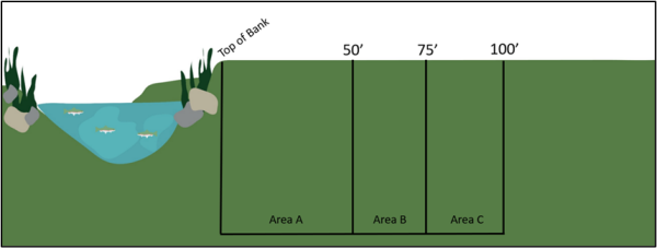
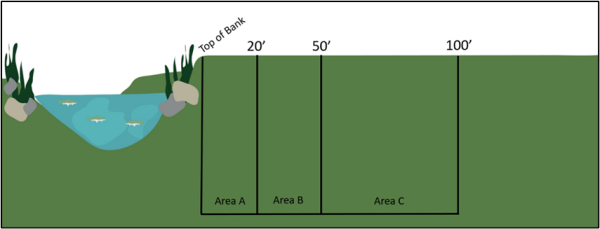
19.72.070 Responsibility For Geologic Hazard And Other Studies
- Geologic studies of surface fault rupture, slope stability and landslide, liquefaction, debris flow, and rockfall hazards often require both engineering geology and geotechnical engineering expertise. Engineering geologic studies shall be performed under the direct supervision of a qualified licensed engineering geologist. Geotechnical engineering studies shall be performed under the direct supervision of a qualified licensed geotechnical engineer.
- When analyzing a conditional use application or other land use proposal, the city may, based on an initial geologic and/or geotechnical study, require that additional studies related to the sensitive lands being developed be completed to address additional geologic hazards that may include, without limitation, hydrology, snow avalanche, etc. All additional studies shall be completed by a city-approved expert in the particular field of study.
19.72.080 Minimum Acceptable Qualifications Of The Engineering Geologist
Engineering geology and the evaluation of geologic hazards is a specialized discipline within the practice of geology requiring technical expertise and knowledge of techniques not commonly used in other geologic disciplines. Therefore, geologic hazard investigations involving engineering geology shall only be accepted by the city when conducted, signed, and stamped by a qualified engineering geologist. The minimum qualifications of the engineering geologist who performs geologic hazard investigations of sensitive lands in the city are:
- An undergraduate or graduate degree in geology, engineering geology, or geological engineering, or closely related field, from an accredited college or university.
- At least five full years of experience in a responsible position in the field of engineering geology in Utah, or in a state with similar geologic hazards and regulatory environment. This experience must demonstrate the engineering geologist's knowledge and application of appropriate techniques in performing geologic hazard studies.
- An active, current Utah State professional Geologist's license.
- In good standing with the Division of Professional and Occupational Licensing of the Utah Department of Commerce.
19.72.090 Minimum Acceptable Qualifications Of The Geotechnical Engineer
Evaluation and mitigation of geologic hazards often require contributions from a qualified geotechnical engineer, particularly in the design of mitigation measures. Geotechnical engineering is a specialized discipline within the practice of civil engineering requiring technical expertise and knowledge of technique not commonly used in civil engineering. Therefore, geologic hazard investigations requiring contributions from a qualified geotechnical engineer will only be accepted by the city when also signed and stamped by a qualified geotechnical engineer. Minimum qualifications of a geotechnical engineer who participates in geologic hazard investigations of sensitive lands in the city are:
- A graduate degree in geological or civil engineering, with an emphasis in geotechnical engineering; or a B.S. degree in civil engineering with at least 12 semester hours of post-B.S. credit in geotechnical engineering, or course content related to evaluation of geologic hazards, from an accredited college or university.
- At least five full years of experience in a responsible position in the field of geotechnical engineering in Utah, or in a state with similar geologic hazards and regulatory environment, and experience demonstrating the engineer's knowledge and application of appropriate techniques in participating in geologic hazard studies.
- An active, current Utah State Professional Engineer's license.
- In good standing with the Division of Professional and Occupational Licensing of the Utah Department of Commerce.
19.72.100 Minimum Acceptable Qualifications Of Other Professionals
The city may require studies of additional geologic hazards that may include, without limitation, hydrology, snow avalanche, etc. The city shall determine the adequacy of the qualifications of professionals performing additional studies based upon the following minimum standards:
- An active, current Utah State professional license in the specified field and in good standing with the Division of Professional and Occupational Licensing of the Utah Department of Commerce; or,
- Where a license from the Utah Division of Professional & Occupational Licensing is not available:
- Demonstrated competence in the specified field as evidenced by a current CV provided to the city for review and approval, showing extensive study in the specified field, experience performing the specified studies and professional competence; and
- Professional certification obtained through a reputable national organization such as LEED, AIA, AICP, ASLA or other applicable equivalent acceptable to the city.
19.72.110 Procedure
Proposals for building or development on sensitive lands shall follow the procedure set forth in this section, which shall consist of four distinct parts: (1) scoping study; (2) conceptual proposal / disturbance permit request; (3) preliminary proposal; and (4) final approval. The DRC shall establish and update from time to time, as necessary, an internal policy for the process described herein. Applications for review by the city shall be filed and processed in the following order:
- Scoping pre-application meeting. The applicant or consultant shall schedule a scoping pre-application meeting with the DRC to evaluate the investigative approach of the engineering geologist/geotechnical engineer. At this meeting, the consultant shall present a work plan that includes locations of anticipated geologic hazards and locations of proposed exploratory excavations, such as test pits, trenches, borings, and cone penetrometer test (CPT) soundings, which, at a minimum, meet the minimum standards of practice. The investigation approach should allow for flexibility due to unexpected site conditions. Field findings may require modifications to the work plan. Upon completion of a successful scoping meeting, the DRC will direct the applicant to prepare an application for land disturbance permit. Summary notes, recordings, and/or minutes shall be kept of all pre-scoping meetings with the DRC.
- Land disturbance permit. No person shall commence or perform any land disturbance, grading, relocation of earth, or any other land disturbance activity on sites greater than or equal to one acre in size or on sites smaller than an acre that are part of a larger development, without first obtaining a land disturbance permit. Application for a land disturbance permit shall be filed with the city engineer on forms furnished by the city for such purposes only after a scoping meeting has taken place with the DRC.
- Proposals for surveying, testing or other design-related activities requiring physical entry into areas located within a sensitive lands district shall be submitted to the DRC for review and modification, approval or denial. Prior to review by the DRC, the areas of proposed disturbance shall be staked at the applicant's expense. Following staking, the city engineer or city geologist shall have at least two business days to observe the staking.
- Thereafter, the DRC, upon receiving a favorable recommendation from the city engineer and geologist, may authorize issuance of a grading permit to allow access to, and permit testing of, the approved areas.
- The permit shall be limited to the staked area of proposed disturbance and may include conditions deemed appropriate by the DRC to protect sensitive areas. As dictated by the DRC, such conditions may include requirements for the following:
- Photo documentation to identify pre-existing types and general locations of vegetation which may need to be protected or replaced.
- The submission of a SWPPP for the implementation of adequate erosion control measures to protect affected areas. Supplemental erosion control measures may also be required between initial disturbances and either construction of permanent improvements or restoration and re-vegetation of the disturbed area.
- Limitations on cuts and fills to ensure that they are made only where necessary to obtain access for required testing.
- Requirements for restoration and re-vegetation of disturbed areas where permanent improvements are not constructed within one year following the disturbance.
- A land disturbance bond (cash bond, cash escrow or bank letter of credit, all in such form as city may require) to cover the expense of re-vegetating disturbed areas and returning graded areas to their natural state.
- Any other reasonable requirement to mitigate the effect of potential interruption caused by the disturbance of the area for conceptual or preliminary activities.
- Photo documentation to identify pre-existing types and general locations of vegetation which may need to be protected or replaced.
- The conceptual plan shall include the following information; provided, however, that the DRC may reasonably modify the following requirements:
- A conceptual development map, drawn at a minimum scale of 1"=100', which shows:
- One or two foot contours;
- Natural slopes of 30% or greater color shaded;
- Proposed development layout of lots, roads, schools, churches, parks, open space, fire stations, commercial, cut or fill slopes or areas of disturbance, and any other proposed land use;
- Labeling of any roads with grades in excess of eight percent (8%); and
- Native vegetation, by type and location.
- One or two foot contours;
- A report which indicates:
- Total development area;
- Total area with over 30% slope
- Number of lots or units proposed;
- Proposed density calculation;
- Evidence of compliance with city stormwater requirements;
- Percentage of each use, such as residential, commercial, recreational, transportation, etc.; and
- Statement of compliance with the design requirements of this chapter.
- Total development area;
- A re-vegetation plan addressing restoration plans for areas disturbed by preliminary activities.
- Following submittal of the items described above and finding by the DRC that all items are satisfactory, the DRC shall approve the concept plan.
- A conceptual development map, drawn at a minimum scale of 1"=100', which shows:
- Proposals for surveying, testing or other design-related activities requiring physical entry into areas located within a sensitive lands district shall be submitted to the DRC for review and modification, approval or denial. Prior to review by the DRC, the areas of proposed disturbance shall be staked at the applicant's expense. Following staking, the city engineer or city geologist shall have at least two business days to observe the staking.
- Preliminary assessment and mitigation. Following conceptual approval, preliminary approval of a hazard assessment plan shall be sought from the DRC. The information and reports required in this subsection are outlined in the appendices to this chapter; shall be submitted as part of an application for preliminary approval; and may be in addition to information otherwise required for preliminary approval for a subdivision or PUD, or a permit for a conditional or permitted use.
- Final approval of assessment and mitigation measures. Final approval of hazard assessment and mitigation measures shall be issued by the DRC. All bonding requirements of this code also shall be satisfied prior to the issuance of the final approval by the community development department.
- Reclamation plan procedure. Any land disturbance in sensitive areas, including test pits, re-grading or alteration of vegetation shall require a reclamation plan. The reclamation plan shall include information about the existing site, the scope of the disturbance, compaction requirements, drainage, impact to native vegetation, slope stabilization, site security, erosion control measures, revegetation, long term measures to mitigate the proposed impact and any other measures that impact the ability to restore the property to a stable, long-term condition. If failure to follow the reclamation plan jeopardizes the safety of the property or results in impact to another property, the city may require a bond, as determined by the DRC.
19.72.120 Geologic Hazard Study Area Maps
- Geologic hazard study areas in the city are defined as any area designated in the city's geologic hazards study area maps. Additional geologic hazard areas may include, but are not necessarily limited to:
- Designated special study areas by the Utah Department of Natural Resources, Utah Geological Survey (UGS), including those areas around hazardous faults in the Utah Geologic Hazards Portal, Earthquake Hazards, Hazardous Faults layer, and Utah Quaternary Fault and Fold Database;
- Geologic units designated as Qm, Qms, Qms1, Qmsy, Qmso, Qmc, Qmg, Qac, Qay, Qg, Qga, Qgy, Qgmy, Qgo, Qgao Qgm, Qgmo, Qmdf, Qaf, Qafy, Qafo, Qaf1, Qaf2, Qaf3, Qaf4, Qaf5, Qafb, Qafp, Qafoe, Qgr, Qmtr, Qmy, Qct, and Tn on the most recent geologic maps published by the UGS;
- Landslide hazard areas defined as:
- Low, moderate, and high landslide susceptibility areas as identified in UGS Map M-228: Landslide Susceptibility Map of Utah;
- Landslide areas identified in the UGS Utah Landslide Database; and
- Areas where slopes are in excess of 30% and those requiring slope stability analyses as defined in this chapter;
- All properties located on alluvial fans and those with drainage channels subject to flash flooding and/or debris flows;
- Other areas where the topography; geology, including soils and bedrock conditions, either on the subject property or adjacent indicate the presence of geologic hazards; and other previously identified geologic hazards that the city finds to be of significance to the health, safety, and welfare of the city’s residents; and
- Site-specific surface-fault-rupture investigations are required for all critical facilities and structures for human occupancy (International Building Code [IBC] Risk Category II, III, and IV) along latest Pleistocene-Holocene faults and for critical facilities (IBC Risk Category IV) along late Quaternary and Quaternary faults. For noncritical facilities for human occupancy (IBC Risk Category II and III) along late Quaternary and Quaternary faults, investigations are recommended, but not required. See the UGS Utah Geologic Hazards Portal, Earthquake Hazards, Hazardous Faults layer and Utah Quaternary Fault and Fold Database to locate Quaternary age faults within the city and to determine their activity class.
- Designated special study areas by the Utah Department of Natural Resources, Utah Geological Survey (UGS), including those areas around hazardous faults in the Utah Geologic Hazards Portal, Earthquake Hazards, Hazardous Faults layer, and Utah Quaternary Fault and Fold Database;
- Geologic hazards study area maps are prepared using the best available scientific information but are necessarily generalized and designed only to indicate areas where hazards may exist and where geologic hazards studies are required. Because such maps are prepared at a non-site-specific scale, geologic hazards may exist that are not shown on the maps. The fact that a site is not shown in a geologic hazards study area for a particular hazard does not exempt the applicant from considering the hazard if evidence is found that it may exist. It is the responsibility of the applicant to consider and identify all geologic hazards on the subject site. If it is subsequently determined that the site has geologic hazards that are not shown on the geologic hazards study area maps, the review process will be pursuant to this chapter.
- Geologic hazards study area boundaries shown on the geologic hazards study area maps will not be systematically adjusted as each individual site-specific study indicates whether or not an actual hazard exists at the site. Geologic hazards study area maps are meant only to define areas within the city where scientific evidence indicates a hazard may exist. However, geologic hazards study area maps may be updated and amended by the city if found to be inaccurate or in error, or as new methods or data are developed to better define areas of potential hazards.
- Where geologic hazards study area maps are thought by an applicant to be inaccurate or in error and require revision, the applicant shall submit to the city technical evidence by a qualified professional supporting the claim and showing the proposed revision. The city will review the information and render a decision. The applicant may appeal that decision by following the appeals process contained in this chapter.
19.72.130 Geologic Hazard Studies And Reports Required
- Any applicant requesting development approval on a parcel of land within a geologic hazard study area or where there are known or readily apparent geologic hazards and the area is not depicted on a geologic hazards study area map, shall submit to the city copies of a site-specific geologic hazard study report that specifically relates to the geologic hazards present on and adjacent to the site that may affect the site.
- A foundation excavation report or observation report must be submitted to the city's building department for all new construction on sensitive lands. This report shall show that the developer or applicant has complied with all requirements and recommendations (including those in previous geotechnical reports that have been conducted for the subject property); shall show any geologic hazards found after excavation but prior to footing and foundation construction; and shall be certified by a licensed geotechnical engineer or engineering geologist as required by this chapter.
19.72.140 Building Permits On Prior-Recorded Lots
- The following submittals and processes are required prior to issuance of a building permit for a new or replacement structure designed for human occupancy and additions to structures designed for human occupancy for all legal lots of record recorded prior to the effective date hereof which are on property noted as restricted for geologic hazard reasons on a recorded plat or within designated geologic hazard study areas. The requirements of this section are in addition to all applicable requirements detailed in this chapter:
- A statement from a Utah-licensed professional civil engineer and a statement from a Utah-licensed professional structural engineer stating that they have reviewed the geologic and geotechnical reports, which may be combined into one report, and that that have designed the structure in accordance with the report recommendations, accounting for any identified geologic and geotechnical hazards in accordance with the currently statewide adopted International Building Code and related standards;
- Written verification from the consultant's issuer of professional errors and omissions liability insurance, in the amount of $2,000,000.00 per consultant, which covers the licensed professional engineering geologist, geotechnical engineer, and structure engineer, and which are in effect on the date of issuance of the building permit by the city; and
- Adherence to all conditions of the currently adopted statewide building and fire codes.
- Prior to the issuance of a certificate of occupancy for a new or replacement structure designed for human occupancy, and additions to structures designed for human occupancy for all parcels recorded prior to the effective date hereof, and which are within a Geologic Hazards Study Area:
- An excavation inspection report shall be submitted by a geotechnical engineer to the city prior to footing placement, which verifies that the proposed building was in accordance with the recommendations of the geologic and geotechnical reports, which may be combined into one report;
- The city may require, at any time, written verification from a geotechnical engineer or Utah-licensed professional structure engineer, that the structure conforms to the recommendations of the original reports and designs, and if not, provides appropriate as-built drawings documenting the changes; and
- All requirements of the currently statewide adopted Utah State Construction and Fire Codes Act must be met.
19.72.150 Geologic Hazard Reports
- Each geologic hazards report shall be site-specific consistent with the requirements of this chapter and shall identify all known or suspected geologic hazards, whether originating on-site or off-site, whether previously identified or previously unrecognized, that may affect the subject property. All geologic hazard reports shall include the original signature and professional seal of the qualified professional. A geologic hazard report may be combined with a geotechnical report and/or contain information on multiple hazards. Geologic hazards reports co-prepared by professional geologists and engineers must include the original signature and wet stamp of both professionals.
- A field review by the city is required during subsurface exploration activities (test pits, trenches, drilling, etc.) to allow the city to evaluate the subsurface conditions, such as the age and type of deposits encountered, the presence or absence of landslides and faults, etc. with the applicant’s consultant. Discussions about questionable features or appropriate setback distances are appropriate, but the city will not assist with field logging, explaining stratigraphy, or give approval of the proposed development during the field review. Exploratory trenches when excavated, shall be open, safe, and in compliance with applicable federal Occupational Safety and Health Administration, State of Utah, and other excavation safety regulations, have the walls appropriately cleaned, and a field log completed by the time of the review. The applicant must provide a minimum notice of 2 days to the city for scheduling the field review.
- Surface fault rupture hazard reports shall contain all requirements described in “Appendix B, Minimum Standards for Surface Fault Rupture Hazard Studies” of this chapter. Surface fault rupture studies shall be conducted by a qualified engineering geologist.
- Slope stability and landslide hazard reports shall contain all requirements described in “Appendix C, Minimum Standards for Slope Stability Hazard Analysis”, of this chapter, Slope stability and landslide studies shall be conducted by a qualified engineering geologist, a qualified geotechnical engineer.
- Liquefaction hazard reports shall contain all requirements described in “Appendix D, Minimum Standards for Liquefaction Hazard Investigations and Evaluations”, of this chapter. Liquefaction investigations are not required for residential construction classified in the International Residential Code as R-3.
- Debris flow hazard reports shall contain all requirements described in “Appendix E, Minimum Standards for Debris Flow Hazard Analyses”, of this chapter. Debris flow hazard investigations shall be conducted by a qualified engineering geologist. Mitigation measures will generally require contributions from geotechnical engineers, hydrologists, or civil engineers.
- Rockfall hazard reports shall contain all requirements described in “Appendix F, Minimum Standards for Rockfall Hazard Analyses”, of this chapter. Rockfall studies shall be conducted by a qualified engineering geologist. Mitigation measures will generally require contributions from geotechnical and/or civil engineers. In addition to the requirements of the aforementioned reports, all geologic hazards reports shall meet the submittal and preparation requirements of this chapter, UGS Circular 128: Guidelines for Investigating Geologic Hazards and Preparing Engineering-Geology Reports, With a Suggested Approach to Geologic-Hazard Ordinances in Utah, Chapter 2, or its successor, and shall include, at a minimum:
- A one to twenty-four thousand (1:24,000) scale geologic map, with references, showing the general surface geology (landslides, rockfall, alluvial fans, etc.), bedrock geology where exposed, bedding attitudes, faults, other geologic structural features, and the location of any other known geologic hazards;
- A detailed site geologic map and geologic cross section(s) of the subject area, at a scale equal to or more detailed than one inch equals 100 feet (1”:100’), showing the locations of subsurface investigations and site-specific geologic mapping performed as part of the geologic hazard investigation, including boundaries and features related to any geologic hazards, topography, and drainage. The site geologic map must show the location and boundaries of the property, geologic hazards, delineation of any recommended setback distances from hazards, and recommended locations for structures. Buildable and non-buildable areas shall be clearly identified;
- Trench and test pit logs, when applicable, prepared in the field and presented in the geologic hazard report with standard geologic nomenclature at a scale equal to or more detailed than one inch equals five feet (1”:5’). Field logs shall be kept by the consultant and may be requested by the city for further review during the project;
- Boring logs, when applicable, prepared with standard geologic and engineering nomenclature and format;
- Listing of aerial photographs used and other supporting information, as applicable;
- Conclusions and recommendations, clearly supported by adequate data included in the report, that summarize the characteristics of the geologic hazards, and that address the potential effects of the geologic conditions and geologic hazards on the proposed development and its occupants, particularly in terms of risk and potential damage;
- Specific recommendations for additional or more detailed studies, as may be required to understand or quantify a geologic hazard;
- An evaluation of whether mitigation measures are required, including an evaluation of multiple, viable mitigation options that include specific recommendations for avoidance or mitigation of the effects of the hazards, consistent with the purposes set forth in this chapter, including design or performance criteria for engineered mitigation measures and all supporting calculations, analyses, modeling or other methods, and assumptions. Final design plans and specifications for engineered mitigation must be signed and stamped by a qualified, Utah-licensed engineer (specializing in geotechnical or civil) and/or structural engineer, as appropriate;
- Specific recommendations for avoidance or mitigation of the effects of the hazards, consistent with the purposes set forth in this chapter, including design or performance criteria for engineered mitigation measures and all supporting calculations, analyses, modeling or other methods, and assumptions. Final design plans and specifications for engineered mitigation must be signed and stamped by a qualified geotechnical, civil and/or structural engineer, as appropriate;
- All data upon which recommendations and conclusions are based shall be clearly stated in the report;
- A statement shall be provided by the engineering geologist regarding the suitability of the proposed development from a geologic hazard perspective; and
- All geologic hazard reports shall be signed and stamped by the Utah-licensed professional(s) that prepared the reports in accordance with Utah Code 58-76-603 (Professional Geologists) and 58-22-603 (Professional Engineers).
- A one to twenty-four thousand (1:24,000) scale geologic map, with references, showing the general surface geology (landslides, rockfall, alluvial fans, etc.), bedrock geology where exposed, bedding attitudes, faults, other geologic structural features, and the location of any other known geologic hazards;
- When a submitted report does not contain adequate data to support its findings, additional or more detailed studies shall be required to explain or quantify a particular geologic hazard or to describe how mitigation measures recommended in the report are appropriate and adequate.
- When a final geologic hazard report indicates that a geologic hazard does not exist within an adopted geologic hazard study area indicated by a map referenced by this article, the city will consider the new geologic information in potentially revising the adopted hazard maps to remove the specific area from the adopted geologic hazard study area.
19.72.160 Submittal Of Geologic Hazard Reports
- All applicants for land use approval within a geologic hazard study area shall prepare and submit a geologic hazard report (which may be combined with geotechnical and/or other geologic reports) pursuant to the requirements of this article prior to any consideration for a concept plan; preliminary or final plat; commercial, institutional, or one-, two-, and multi-family dwelling; or any conditional use permit which requires site plan approval. The applicant is required to submit the following additional information with the report:
- A written, stamped certification from a Utah-licensed professional geologist that the geologic hazard report has been prepared pursuant to the requirements of this chapter;
- A written, stamped certification from a Utah-licensed professional geologist and a professional engineer that every proposed development lot, building pad, and parcel does not present an unreasonable or unacceptable risk to the health, safety, and welfare of persons or property, including buildings, storm drains, public streets, culinary water facilities, utilities, or critical facilities, whether off site, on adjacent properties, or on site, because of the presence of geologic hazards or because of modifications to the site due to the proposed land use;
- A written, stamped certification from a Utah-licensed professional geologist and a professional engineer that every proposed development lot, building site, and parcel layout demonstrates that, consistent with regional standards of practice, the identified geologic hazards can be mitigated to a level where the risk to human life and damage to property are reduced to an acceptable and reasonable level in a manner which will not violate applicable federal, state, and local statutes, ordinances, and regulations. Mitigation measures shall consider in their design, the intended aesthetic functions of other governing ordinances of the city;
- A written, stamped certification from a Utah-licensed professional geologist and a professional engineer along with a mitigation plan, if necessary, that demonstrates that the identified hazards or limitations will be addressed without impacting or adversely affecting off site areas, including adjacent properties. Mitigation measures must be reasonable and practical to implement and shall not require ongoing maintenance by property owners; and
- Written verification from the issuer of professional errors and omissions liability insurance, in the amount of $2,000,000.00 each, which covers the Utah-licensed professional geologist and professional engineer, and which are in effect on the date of preparation and submittal of all required reports and certifications.
- A written, stamped certification from a Utah-licensed professional geologist that the geologic hazard report has been prepared pursuant to the requirements of this chapter;
19.72.170 Review Of Geologic Hazard Reports
- The city shall review any proposed land use which requires preparation of a geologic hazards report under this chapter to determine the possible risks to the safety of persons, property, and city infrastructure from geologic hazards.
- Prior to consideration of any request for preliminary plat approval, conditional use approval and/or site plan approval of property, the required geologic hazard reports shall be submitted to the city for review.
- The city will endeavor to complete each review in a reasonable time frame within 45 days.
- All direct costs associated with the review of geologic hazard reports shall be paid by the applicant.
- The city shall retain a copy of each geologic hazard report in the community development department’s project file.
- The city shall determine whether the report complies with all the standards set forth in this chapter, including the following:
- Suitable geologic hazard reports have been prepared by qualified, Utah-licensed professionals.
- The proposed land use does not present an unreasonable risk to the health, safety, and welfare of persons or property, including buildings, storm drains, public streets, culinary water facilities, utilities or critical facilities, whether off-site or on-site, or to the aesthetics and natural functions of the landscape, such as slopes, streams, other waterways, drainage, or wildlife habitat, whether off-site or on-site, because of the presence of geologic hazards or because of modifications to the site due to the proposed land use.
- The proposed land use demonstrates that, consistent with the state of the practice, the identified geologic hazards can be mitigated to a level where the risk to human life and damage to property are reduced to an acceptable and reasonable level in a manner which will not violate applicable federal, state, or local statutes, ordinances, or regulations. Mitigation measures should consider, in their design, the intended aesthetic functions of other governing ordinances. The applicant must include with the geologic hazards reports a mitigation plan that defines how the identified hazards or limitations will be addressed without impacting or adversely affecting off-site areas. Implementation of mitigation measures must be reasonable and practical to implement, especially if such measures require on-going maintenance by property owners.
- Should a geologic report be found deficient with respect to this chapter and/or the current, regional state of practice, a letter will be provided to the applicant summarizing the specific deficiencies. If a submitted report is found deficient three times or a report was excessively deficient, the city may notify the Utah Division of Occupational & Professional Licensing about the licensed professional(s) deficient reports that were submitted to a public entity that were not in compliance with Utah Rules R156-76-502 (Professional Geologists) and/or R156-22-502 (Professional Engineers).
- Suitable geologic hazard reports have been prepared by qualified, Utah-licensed professionals.
- The city may set other requirements that it deems necessary to mitigate any geologic hazards and to ensure that the purposes of this chapter are met. These other requirements may include, without limitation, the following:
- Additional or more detailed investigations and professional certifications to understand or quantify the hazard and/or determine whether mitigation measures recommended in the report are adequate;
- Specific mitigation requirements, establishing buildable and non-buildable areas, limitations on slope grading, controls on grading, and/or re-vegetation;
- Grading plans, when required, shall be prepared, signed, and sealed by a Utah-licensed professional engineer. As built grading plans, when required, shall be signed and sealed by the project geotechnical engineer as well as the professional engineer that prepared the grading plans. Grading plans, when required, shall include, at a minimum, the following:
- Maps of existing and proposed contours and the source and accuracy of topographic data used;
- Present and proposed slopes for each graded area;
- Existing and proposed drainage patterns;
- Location and depth of all proposed cuts and fills;
- Description of methods to be employed to achieve soil and/or rock stabilization and compaction, as appropriate;
- Location and capacities of proposed drainage, structures, and erosion control measures based on maximum runoff for a 100-year storm or greater;
- Location of existing buildings, structures, roads, wells, retention and other basins, and on-site sewage disposal systems on or within 100 feet of the site that may be affected by the proposed grading and construction; and
- Plan for monitoring and documentation of testing, field inspections during grading, and reporting to the city;
- Maps of existing and proposed contours and the source and accuracy of topographic data used;
- Installation of monitoring equipment and seasonal monitoring of surface and other subsurface geologic conditions, including groundwater levels; and
- Other requirements such as time schedules for completion of the mitigation and phasing of development.
- Additional or more detailed investigations and professional certifications to understand or quantify the hazard and/or determine whether mitigation measures recommended in the report are adequate;
- As a condition of approval of any development of sensitive lands which requires a geologic hazards report, the city may also set additional requirements necessary to protect the health, safety, and welfare of its residents, protect the city’s infrastructure and financial health, and minimize potential adverse effects of geologic hazards to public health, safety, and property.
- The city may require the engineering geologist and geotechnical engineer that prepared the geologic hazard and/or geotechnical report(s) to be on site, at the applicant’s cost, during certain phases of development and construction, particularly during grading phases, the construction of retaining walls, and geologic hazard mitigation. For any real property being developed based on a geologic hazard and/or geotechnical report which has been accepted by the city, no final inspection shall be completed, certificate of occupancy issued, or performance bond released until the geotechnical engineer or engineering geologist who signed, stamped, and approved such report certifies in writing that the completed improvements and structures conform to the descriptions and requirements contained in such report, and that all the required inspections were made and approved by the engineering geologist and geotechnical engineer that prepared said report(s). If the preparing engineering geologist and geotechnical engineer are unavailable, an engineering geologist and geotechnical engineer, similarly qualified and licensed in Utah, shall provide the certifications.
- An applicant may appeal any decision made under the provisions of this chapter only after the city has issued a written review of a report. The city’s appeals hearing officer shall serve as the appeal authority for any dispute under this chapter. Any such appeal shall set forth the specific grounds or issues upon which the appeal is based. The appeal shall be submitted in writing to the director within 30 days after the city’s issuance of the written review or other decision that is the subject of such appeal. The city may assemble a professional panel of three qualified experts to assist the appeal authority for any technical dispute. The panel shall consist of an expert designated by the city, an expert designated by the applicant, and an expert chosen by the city’s and the applicant’s designated experts. If the city’s and the applicant’s designated experts cannot reach a consensus of the third expert within 30 days, the city shall select the third expert. The costs of the appeal process shall be paid by the applicant.
19.72.180 Disclosure When A Geologic Hazard Report Is Required
- Whenever a geologic hazard report is required under this chapter, the owner of the affected parcel shall record a signed, notarized disclosure notice, running with the land, in a form satisfactory to the city prior to the city's approval of any development or subdivision of such parcel or commencement of construction activity. The recorded disclosure shall include the following:
- Notice that the parcel is located within a geologic hazards study area as shown on the geologic hazards study area map or as otherwise defined in this chapter; and
- Notice that a geologic hazards report was prepared and is available for public inspection in the city's files.
- Where geologic hazards, related setbacks, and non-buildable areas are delineated in a subdivision, the owner shall also place additional notification on the plat stating the above information, prior to final approval and recording of the plat.
19.72.190 Warning And Disclaimer
The city’s geologic hazards study area maps represent only those potentially hazardous areas known to the city and should not be construed to include all possible potential hazard areas. This chapter and the geologic hazards study area maps referenced herein may be amended by the city as new information becomes available pursuant to procedures set forth in this chapter. The provisions of this chapter do not in any way assure or imply that areas outside the geologic hazards study area maps boundaries are free from the possible adverse effects or risk of geologic hazards. This chapter shall not create any liability on the part of the city or any of its officers, employees, reviewers, consultants, agents or contractors for any damages from geologic hazards that result from reliance on this chapter, or any administrative requirement or decision lawfully made hereunder.
19.72.200 Change Of Use
No change in use which results in the conversion of a building or structure from one that is not used for human occupancy to one that is so used shall be permitted unless the building or structure complies with the provisions of this chapter.
19.72.210 Maps And Appendices
The maps and appendices for this chapter are attached. Click to view them if reviewing an electronic copy of this chapter.
403
424
Appendix A - Geologic Hazards Study Area Maps
Appendix B - Minimum Standards For Surface Fault Rupture Hazard Studies
- INTRODUCTION. The Wasatch Fault Zone is a major tectonic feature of the intermountain region in the western United States. It extends from Fayette, Utah at the south to Malad, Idaho at the north, comprising about 230 miles. Surface faulting has occurred along the Wasatch Fault Zone in northern Utah throughout late Pleistocene and Holocene time. "Surface faulting" is a fault-related offset or displacement of the ground surface that may occur in an earthquake. The Wasatch Fault Zone consists of a series of normal-slip fault segments where the earth experiences relative downward movement on the west side and upward movement on the east side. Ten major fault segments are recognized along the Wasatch Fault Zone, which are believed to be independent in regard to their potential for surface faulting. These segments have distinct geomorphic expression and are clearly visible on aerial photographs. In the Salt Lake Valley, the Wasatch Fault Zone is represented by the Salt Lake City segment, which extends about 23 miles along the eastern edge of the valley. A portion of the Salt Lake City segment of the Wasatch Fault Zone is present in the foothills of Cottonwood Heights (the “city”) on the eastern side of city. Documentation of repeated Holocene movements suggest that at least four major earthquake events have occurred in the last 6,000 years along Wasatch Boulevard near the mouth of Little Cottonwood Canyon. In the event of an earthquake, a fault could break the ground surface below or near a structure and cause significant property damage, injuries and loss of life. In order to reduce risk from surface- fault-rupture hazards and to protect public health and safety, the city has defined a boundary for the sensitive lands that may have a heightened potential for surface fault ruptures and is requiring study for all new development or re-development within this area. Quaternary faults located within the Surface Fault Rupture Hazard Study Area should be considered active until proven otherwise. The city requires a site-specific geologic study for all properties that may be impacted by the Wasatch Fault Zone. The study must address the surface fault rupture potential and assess the suitability of the proposed development. In the event that a fault is discovered and deemed active (i.e., Holocene-age), appropriate building setbacks are required to minimize the potential damage during an earthquake. The site-specific surface fault rupture hazard study requires a field investigation. This includes geologic documentation of an excavated trench or other pre-approved method of exploration and accompanying report that addresses the findings. The following information in this appendix describes the minimum standards required by the city for the surface fault rupture hazard study. In addition to the minimum standards contained in this appendix, these investigations and reports shall conform with the Guidelines for Evaluating Surface-Fault-Rupture Hazards in Utah (UGS Circular 128, or its successor), as appropriate.
- Purposes.
- The purposes of establishing minimum standards for surface fault rupture hazard studies are to:
- Protect the health, safety, welfare, and property of the public by minimizing the potential adverse effects of surface fault ruptures and related hazards.
- Provide guidance for property owners and land developers in performing reasonable and adequate studies of sensitive lands in the city.
- Provide consulting engineering geologists with a common basis for preparing proposals, conducting investigations, and recommending setbacks.
- Provide a consistent and objective framework for review of fault study reports.
- The procedures in this appendix are intended to provide the developer and consulting engineering geologist with an outline of appropriate exploration methods, standardized report information, and city expectations.
- These standards are the minimum level of effort required in conducting surface fault rupture hazard studies within the city. Considering the complexity of evaluating surface and near-surface faults, additional effort beyond the minimum standards may be required at some sites to adequately address the surface fault rupture hazard. The information presented in this appendix does not relieve the engineering geologist from his/her duty to perform additional geologic or engineering services he/she believes are necessary to assess the surface fault rupture potential at a site. In the interest of public safety, the city may, at any time, require additional information, studies, tests or other work that is not included in this appendix.
- The purposes of establishing minimum standards for surface fault rupture hazard studies are to:
- Properties requiring a fault investigation.
- Before approval of any land use, a fault study is required for properties within the surface fault rupture special study area that is located near the Wasatch Fault Zone, or any other property within the city that observes a fault trace during excavation. Appendix A of city code chapter 19.72 (“chapter 19.72”) contains the Surface Fault Rupture Hazard Study Area Map (Map 1) that identifies areas with known active faults in the city. Properties within this area must perform site-specific geologic investigations. Development of any parcel within the Surface Fault Rupture Hazard Study Area requires submittal and review of a site-specific fault study prior to receiving a land use or building permit from the city. It is the responsibility of the applicant to retain a qualified (as provided in chapter 19.72) engineering geologist to perform the fault study.
- In addition, a fault study may be required if onsite or nearby fault-related features not shown on the Surface Fault Rupture Hazard Study Area Map are identified during the course of other geologic or geotechnical studies performed on or near the site or during construction.
IBC Risk Category Surface Fault Rupture Hazard Investigation
(Fault Movement Age)
Latest Pleistocene-Holocene Late Quaternary Quaternary I Optional Optional Optional II(a)1 Required Prudent Optional II(b)2 Required Required Prudent III Required Required Required IV Required Required Required 1 - Single family dwellings. 2 - Buildings and other structures except those listed in IBC Risk Categories I, II(a), III, and IV - The requirement for site-specific investigation of surface faulting depends on fault activity level as defined by the most recent Wester States Seismic Policy Council (WSSPC) Policy Recommendation (PR) for faults that cross properties with proposed structures. The current PR is 21-3: Definitions of Recency of Surface Faulting for the Basin and Range Province and defines latest Pleistocene-Holocene, late Quaternary, and Quaternary faults as:
- Latest Pleistocene-Holocene fault – A fault whose movement in the past 15 ka [15,000 years] has been large enough to break the ground surface.
- Late Quaternary fault – A fault whose movement in the past 130 ka [130,000 years] has been large enough to break the ground surface.
- Quaternary fault – A fault whose movement in the past 2.6 Ma [2.6 million years] has been large enough to break the ground surface.
The city requires site-specific investigation on parcels with latest Pleistocene-Holocene faults for all new critical facilities and structures for human occupancy (IBC Risk Category II, III, and IV structures), on parcels with latest Pleistocene-Holocene and late Quaternary faults for all new critical facilities (IBC Risk Category III and IV structures), and on parcels with the faults listed in item B below.
- The UGS Utah Geologic Hazards Portal, Earthquake Hazards, Hazardous Faults layer and UGS Utah Quaternary Fault and Fold Database provide the latest information on Quaternary faulting in Utah to determine fault activity levels as defined above and where surface fault rupture Geologic Hazard Study Areas have been defined. Where data are inadequate to determine the fault activity class, the fault shall be assumed to be latest Pleistocene-Holocene, pending detailed surface-fault-rupture and/or paleoseismic investigations. The database currently includes the following mapped Quaternary faults within the city:The city may require a site-specific investigation if on-site and/or nearby fault-related features not shown in the database are identified during other geologic or geotechnical investigations or during project construction. Investigations are required for all critical facilities, whether near a mapped Quaternary fault or not, to ensure that previously unknown faults are not present. If evidence for a Quaternary fault is found, subsurface investigations are required and trenching to locate a suitable buildable area may be necessary (IBC Sections 1704.6.1 and 1803.5.11).
Wasatch fault zone, Salt Lake City section - Latest Pleistocene-Holocene fault - When an alternative subsurface exploration plan is proposed in lieu of paleoseismic trenching, a map and written description and plan shall be submitted to the city for review, prior to the scoping meeting and exploration implementation. The plan must include at a minimum, a map of suitable scale showing the site limits, surface geologic conditions within 2000 feet of the site boundary, the location and type of the proposed exploration, the anticipated subsurface geologic conditions, and a through description of why the alternative exploration is being proposed.
- Before approval of any land use, a fault study is required for properties within the surface fault rupture special study area that is located near the Wasatch Fault Zone, or any other property within the city that observes a fault trace during excavation. Appendix A of city code chapter 19.72 (“chapter 19.72”) contains the Surface Fault Rupture Hazard Study Area Map (Map 1) that identifies areas with known active faults in the city. Properties within this area must perform site-specific geologic investigations. Development of any parcel within the Surface Fault Rupture Hazard Study Area requires submittal and review of a site-specific fault study prior to receiving a land use or building permit from the city. It is the responsibility of the applicant to retain a qualified (as provided in chapter 19.72) engineering geologist to perform the fault study.
- References and sources.
- Guidelines for Evaluating Surface Fault Rupture Hazards in Utah (AEG, 1987).
- Guidelines to geologic and seismic reports (CDMG, 1986a).
- Guidelines for preparing engineering geologic reports (CDMG, 1986b).
- Guidelines for Evaluating Potential Surface Fault Rupture/Land Subsidence Hazards in Nevada (Nevada Earthquake Safety Council, 1998).
- Fault Setback Requirements to Reduce Fault Rupture Hazards in Salt Lake County (Batatian and Nelson, 1999).
- Salt Lake County Geologic Hazards Ordinance (2002).
- Draper City Geologic Hazard Ordinance (2003).
- Guidelines for evaluating surface-fault-rupture hazards in Utah (Christenson and others, 2003).
- Guidelines for Investigating Geologic Hazards and Preparing Engineering-Geology Reports, with Suggested Approach to Geologic-Hazard Ordinance in Utah (Bowman and Lund, 2016).
- Purposes.
- MINIMUM STANDARDS FOR FAULT STUDIES. The following are the minimum standards for a comprehensive surface fault rupture study investigation.
- Scoping meeting. A scoping meeting with the DRC shall be scheduled by the consultant geologist. At this meeting, the developer, the city and the consultant will evaluate the fault investigation approach. The consultant should bring a site plan to the meeting that shows the following information. The investigative approach should allow for flexibility due to unexpected site conditions. The field findings may require modification to the work plan:
- Proposed building locations (if known);
- Expected fault location(s) and orientation;
- Proposed trench locations, orientation, length, and depth (see Section 2.2, Fault Investigation Method);
- Extent of impact to vegetation and trees; and
- Method of controlling erosion and managing storm water.
- Fault investigation method. Inherent in fault study methods is the assumption that future faulting will recur along pre-existing faults and in a manner consistent with past displacement. The focus of fault studies is therefore to accurately locate existing faults. If faults are documented, the investigation shall also include (a) evaluation of the age of movement along the fault trace(s), and (b) estimation of amounts of past displacement, which is required in order to derive fault setbacks.
- Previous studies and aerial photograph review. A fault study shall include review of available literature pertinent to the site and vicinity, including previous published and unpublished geologic/soils reports, LiDAR image interpretation, and interpretation of available stereo-paired aerial photographs. The photographs reviewed should include more than one set and should include pre-urbanization aerial photographs, if available. Efforts must be made to accurately plot the locations of mapped or inferred fault traces on the property as shown by previous studies in the area.
- Exploration methods. Sub-surface trenching exploration is required. The engineering geologist shall clean and document (“log”) trench exposures as described in Section 2.3.5. Existing faults may also be identified and mapped in the field by direct observation of young, fault-related geomorphic features, and by examination of aerial photographs. If trenching is not feasible due to the presence of shallow ground water or excessive fill, supplemental methods such as closely spaced Cone Penetration Test (CPT) soundings may be employed. Such supplemental methods must be discussed with the city prior to implementation and should be clearly described in the report.
- In lieu of conventional trenching or the CPT method, an alternative subsurface exploration program may be acceptable, depending upon site conditions. Such a program may consist of geophysical exploration techniques or a combination of other techniques.
- When an alternative exploration program is proposed, a written description of the proposed exploration program along with an exploration plan should be submitted to the city for review and approval, prior to the exploration. The plan must include, at a minimum, a map of suitable scale showing the site limits, surface geologic conditions within several thousand feet of the site boundary, the location and type of the proposed alternative subsurface exploration, and the anticipated earth materials present at depth on the site.
- The actual subsurface exploration program to be used on any specific parcel will be determined on an individual basis, considering the current state of technical knowledge about the fault zone and information gained from previous exploration on adjacent or nearby parcels. At all times, consideration must be given to safety, and trenching should comply with all applicable safety regulations.
- Trench siting.
- Exploratory trenches must be oriented approximately perpendicular to the anticipated trend of known fault traces. The trenches shall provide the minimum footage of trenching necessary to explore the portion of the property situated in the surface fault rupture study area, such that the potential for surface fault rupture may be adequately assessed. When trenching to determine if faults might affect a proposed building site, the trench should extend beyond the building footprint at least the minimum setback distance for the building type (see Table A-1).
- Test pits or potholes alone are neither adequate nor acceptable. In some instances more than one trench may be required to cover the entire building area, particularly if the proposed development involves more than one building. Where feasible, trenches shall be located outside the proposed building footprint, as the trench is generally backfilled without compaction, which could lead to differential settlement beneath the footings. Supplemental trenching may be required in order to:
- Further refine fault locations (or the absence thereof);
- Accurately define building restriction areas, and/or;
- Provide additional exposures for evaluating the age of movement along fault traces.
- Location determination. All trenches and fault locations must be surveyed by a registered professional land surveyor. The extrapolation of subsurface conditions should not exceed 300 feet. Fault locations should be surveyed with an accuracy of 0.1 foot or better, so that structural setbacks can be developed. The fault locations (and all other features shown in the site plans) must be tied to a minimum of two Salt Lake County section corner monuments and the coordinate data shall be in US State Plane NAD83 (US Survey Feet). Other features in the site plan shall include property lines, building footprint, geologic features, utilities, existing structures, roadway, fences, etc. The location of all features, including the fault lines, shall be wet stamped and certified by the land surveyor.
- Depth of excavation.
- The depth of the trenches will ultimately depend on the trench location, occurrence of ground water, stability of subsurface deposits, and the geologic age of the subsurface geologic units. As a minimum, however, trenches shall extend substantially below the A and B soil horizons and well into distinctly bedded Pleistocene-age materials, if possible. Where possible, the trenches should extend below Holocene deposits and should expose contacts between Holocene materials and the underlying older materials.
- Appropriate safety measures pertaining to trench safety for ingress, egress, and working in or in the vicinity of the trench must be implemented and maintained. It is the responsibility of the person in the field directing trench excavation to ensure that fault trenches are excavated in compliance with current Occupational Safety and Health Administration excavation safety regulations.
- Trench backfilling methods and procedures should be documented in order to establish whether additional corrective excavation, backfilling, and compaction should be performed at the time of site grading.
- In cases where Holocene (i.e., active) faults may be present, but pre- Holocene deposits are below the practical limit of excavation, the trenches must extend at least through sediments that are clearly older than several fault recurrence intervals. The practical limitations of the trenching must be acknowledged in the report and recommendations must reflect resulting uncertainties.
- Documenting trench exposures. Trench walls shall be cleaned of debris and backhoe smear prior to documentation. Trench logs shall be carefully drawn in the field at a minimum scale of 1-inch equals 5-feet (1:60) following standard and accepted fault trench investigation practices. Vertical and horizontal control must be used and shown on trench logs. Trench logs must document all significant geologic information from the trench and should graphically represent the geologic units observed; see Section 2.6.3(E). The strike, dip, and net vertical displacement (or minimum displacement) of faults must be noted.
- Age dating.
- The engineering geologist shall interpret the ages of geologic units exposed in the trench. When necessary, radiocarbon or other age determinations methods shall be used. If evidence of faulting is documented, efforts shall be made to date the time of latest movement to determine whether recent (Holocene) displacement has occurred by using appropriate geologic and/or soil stratigraphic dating techniques. When necessary, obtain radiocarbon or other age determinations.
- Many of the surficial deposits within Salt Lake Valley were deposited during the last pluvial lake cycle, referred to as the Bonneville lake cycle. Although late-stage Bonneville lake cycle sediments do not correspond to the Pleistocene-Holocene boundary (i.e., Bonneville lake cycle deposits are older than 10,000 years old), for purposes of evaluating fault activity, these deposits provide a useful regional datum, particularly when the entire Holocene sequence of sediments is not present.
- For practical purposes, and due to documented Holocene displacement along the Salt Lake segment of the Wasatch fault, any fault which displaces late-stage Bonneville Lake Cycle deposits should be considered active unless the Bonneville deposits are overlain by clearly unfaulted early Holocene-age deposits. Conversely, the presence of demonstrably unbroken, undeformed, and stratigraphically continuous Bonneville sediments constitutes reasonable geologic evidence for the absence of active faulting.
- Field Review. A field review by the city’s geologist is required during exploratory trenching. The applicant must provide a minimum of two business days notice to schedule the field review with the city. The trenches should be open, safe, cleaned, and a preliminary log completed at the time of the review. The field review allows the city to observe the subsurface data such as the age, type of sediments, and presence or absence of faulting with the consultant. Discussions about questionable features or an appropriate setback distance are encouraged, but the city will not help log the trench, explain the stratigraphy, or give verbal approval of the proposed development during the field review.
- Recommendations for fault setbacks.
- Determination of the appropriate setback distance from a hazardous fault shall be made in conformance with the Guidelines for Evaluating Surface-Fault-Rupture Hazards in Utah (Lund and others, 2020; UGS Circular 128, Chapter 3, or its successor). To address wide discrepancies in fault setback recommendations, the city has also adopted the fault setback calculation methodology for normal faults of Batatian and Nelson (1999) and Christenson and others (2003). The consultant should use this method to establish the recommended fault setback for critical facilities and structures designed for human occupancy. If another fault setback method is used, the consultant must provide justification in the report for the method used. Faults and fault setbacks must be clearly identified on site plans and maps.
- The minimum setbacks are based on the type and occupancy of the proposed structure as shown in Table A-1. The setbacks should be calculated using the following formulas presented below, and then compared to the minimum setback established in Table A-1. The greater of the two shall be used as the setback. Minimum setbacks apply to both the hanging wall and footwall blocks.
- Top of slope and/or toe of slope setbacks required by the local Building Code must also be considered; again, the greater setback must be used.
- Downthrown Fault Block (Hanging Wall)
- The fault setback for the downthrown block will be calculated using the following formula: S=U (2D+F/tanӨ) where:
- S = Setback within which structures for human occupancy are not permitted;
- U = Criticality Factor, based on the proposed occupancy of the structure (see Table A-1)
- D = Expected maximum fault displacement per event (assumed to be equal to the net vertical displacement measured for each past event)
- F = Maximum Depth of footing or subgrade portion of the building
- Ө = Dip of the fault (degrees)
- The fault setback for the downthrown block will be calculated using the following formula: S=U (2D+F/tanӨ) where:
- Upthrown Fault Block (Footwall)
- The dip of the fault and depth of the subgrade portion of the structure are irrelevant in calculating the setback on the upthrown fault block. Therefore, the setback for the upthrown side of the fault will be calculated as: S=Ux2D
- The setback is measured from the portion of the building closest to the fault, whether subgrade or above grade. Minimum setbacks apply as discussed above.
- Small displacement faults. Small-displacement faults are not categorically exempt from structure setback requirements. However, if structural risk-reduction measures are proposed for these faults, the following criteria must be met:
- Reasonable geologic data indicating that future surface displacement along the faults will not exceed 4 inches (100 mm) of displacement (“small displacement faults”) following the guidelines in UGS Circular 128 or its successor; and
- Specific structural risk-reduction options such as foundation reinforcement may be acceptable for some small-displacement faults in lieu of setbacks. Structural options must minimize structural damage.
- Fault studies must still identify faults and fault displacements (both net vertical displacements and horizontal extension across the fault or fault zone) and consider the possibility that future displacement amounts may exceed past amounts. If structural risk-reduction measures are proposed for small displacement faults, the following criteria must be addressed:
- Reasonable geologic data indicating that future surface displacement along the particular fault will not exceed 4 inches.
- Specific structural mitigation to minimize structural damage and ensure safe occupant egress.
- A Utah-licensed structural engineer must provide appropriate designs and the city shall review the designs.
- Required outline for surface fault rupture hazard studies.
- The information described herein may be presented as a separate surface fault rupture hazard report or it may be incorporated within other geology or engineering reports that may be required for the property.
- The report shall contain a conclusion regarding the potential risk of surface fault rupture on the subject property and a statement addressing the suitability of the proposed development from a surface fault rupture hazard perspective. If exploration determines that there is a potential for surface rupture due to faulting, or if gradational contacts or other uncertainties associated with the exploration methods preclude the determination of absence of small fault offsets, the report should provide estimates of the amplitude of fault offsets that might affect habitable structures.
- Surface fault rupture hazard reports submitted to the city are expected to follow the outline and address the subjects presented below. However, variations in site conditions may require that additional items be addressed, or permit some of the subjects to be omitted (except as noted).
- Report.
- Statement of the purpose and scope of work. The report shall contain a clear and concise statement of the purpose of the study and the scope of work performed for the study.
- Site description and conditions. The report shall include information on geologic units, graded and filled areas, vegetation, geomorphic features, existing structures, and other factors that may affect site development, choice of investigative methods, and the interpretation of data.
- Geologic and tectonic setting. The report shall contain a clear and concise statement of the general geologic and tectonic setting of the site and surrounding vicinity. This section should include a discussion of active faults in the area, paleoseismicity of the relevant fault system(s), and should reference relevant published and unpublished geologic literature.
- Methods of investigation.
- Review of published and unpublished maps, literature and records concerning geologic units, faults, surface and ground water, and other factors.
- Stereoscopic interpretation of aerial photographs to detect fault-related topography, vegetation or soil contrasts, and other lineaments of possible fault origin. Reference the photograph source, date, flightline numbers, and scale. Salt Lake County has an excellent collection of stereoscopic aerial photographs dating back to 1937 (including 1937, 1940, 1958, 1964, and 1985).
- Observations of surface features, both on-site and offsite, including mapping of geologic and soil units; geomorphic features such as scarps, springs, and seeps (aligned or not); faceted spurs, offset ridges or drainages; and geologic structures. Locations and relative ages of other possible earthquake-induced features such as sand blows, lateral spreads, liquefaction, and ground settlement should be mapped and described. Slope failures, although they may not be conclusively tied to earthquake causes, should also be noted.
- The report shall include a description of the program of subsurface exploration, including trench logs, purpose of trench locations, and a summary of trenching or other detailed, direct observation of continuously exposed geologic units, soils, and geologic structures. All trench logs shall be at a scale of at least 1-inch is equal to five-feet.
- The report must describe the criteria used to evaluate the ages of the deposits encountered in the trench, and clearly evaluate the presence or absence of active (Holocene) faulting.
- Conclusions.
- Conclusions must be supported by adequate data and shall contain, at a minimum a summary of data upon which conclusions are based.
- Location of active faults, including orientation and geometry of faults, amount of net slip along faults, anticipated future offset, and delineation of setback areas.
- Degree of confidence in and limitations of data and conclusions.
- Recommendations. Recommendations must be supported by adequate geologic data and appropriate reasoning behind each statement. Minimum recommendations shall include:
- Recommended setback distances per Section 2.4. Supporting calculations must be included. Faults and setbacks must be shown on site maps and final recorded plat maps.
- Other recommended building restrictions or use limitations (i.e., placement of detached garages, swimming pools, or other non-habitable structures).
- Need for additional or future studies to confirm buildings are not sited across active faults, such as inspection of building footing or foundation excavations by the consultant.
- Report references. Reports must include citations of literature and records used in the study, referenced aerial photographs or images interpreted (air-photo source, date and flight number, scale), and any other sources of data and information, including well logs, personal communications, etc.
- Support information. At a minimum, each geologic report must include the following support information:
- Location map. A site location map depicting topographic and geographic features and other pertinent data. Generally a 1:24,000-scale USGS topographic base map will suffice.
- Geologic map. A regional-scale map (1:24,000 to 1:50,000 scale) is generally adequate. Depending on site complexity, a site-scale geologic map (minimum 1 inch= 200 ft or more detailed) may also be necessary. The map should show Quaternary and bedrock geologic units, faults, seeps or springs, soil or bedrock slumps, and other geologic and soil features existing on and adjacent to the project site. Geologic cross-sections may be included as needed to illustrate 3-dimensional relationships.
- Site plan and fault map. A detailed survey-grade site plan is required. The site plan shall be prepared and certified by a licensed surveyor. The site plan should be at a minimum scale of at least 1 inch = 200 feet and should clearly show site boundaries, proposed building footprints, existing structures, streets, slopes, drainages, exploratory trenches, boreholes, test pits, geophysical traverses, utilities, property lines, fences, slopes, trees, retaining walls, adjacent structures and any other appurtenant features. The site plan shall include the locations of subsurface investigations and site-specific geologic mapping performed as part of the geologic investigation, including boundaries and features related to any geologic hazards, topography, and drainage. The site map must also show the surface fault rupture hazard study area within the subject site the locations of all faults identified during the investigation conducted for the subject site including inferred location of the faults between trenches and must show all recommended setbacks from identified faults and from the ends of trenches located within the surface fault rupture hazard study area. The site map must show the location of all proposed flexible expansion joints for utilities. Both buildable and non-buildable areas shall be clearly identified. All features on the map shall be tied to a minimum of two public survey monuments tied with bearings and distances. The datum shall be submitted in US State Plane NAD83 (US Survey Feet) and wet-stamped by a licensed surveyor. The site map should include a legend describing pertinent items shown on the map.
- Exploratory trench logs. Trench logs are required for each trench excavated as part of the study, whether faults are encountered or not. Trench logs shall accurately depict all observed geologic features and conditions. Trench logs are hand- or computer-generated maps of excavation walls that show details of geologic units and structures. Logs must be submitted with a scale and not be generalized or diagrammatic. The minimum scale is 1 inch = 5 feet (1:60) with no vertical exaggeration. Trench logs must accurately reflect the features observed in the trench (see Section 2.3.6). Photographs shall not be used as a substitute for trench logs. However, it is recommended that a photographic log of the trench also be created.
- Contents of trench logs. Trench logs shall include orientation and indication of which trench wall was logged; trench top and bottom; stratigraphic contacts; stratigraphic unit descriptions including lithology, USCS soil classification, genesis (geologic origin), age, and contact descriptions; soil (pedogenic) horizons; marker beds; and deformation or offset of sediments, faults, and fissures. Other features of tectonic significance such as buried scarp free-faces, colluvial wedges, in- filled soil cracks, drag folds, rotated clasts, lineations, and liquefaction features including dikes, sand blows, etc. should also be shown. Interpretations of the age and origin of the deposits and any faulting or deformation must be included, based on depositional sequence. Fault orientation and geometry (strike and dip), and amount of net displacement must be measured and noted. Provide evidence for the age determination of geologic units. For suspected Holocene faults where unfaulted Holocene deposits are deeper than practical excavation depths, clearly state the study limitations.
- Exploratory boreholes and CPT soundings. If boreholes or CPT soundings are utilized as part of the investigation, reports shall include the logs of the borings/soundings. Borehole logs must include lithology descriptions, interpretations of geologic origin, USCS soil classification or other standardized engineering soil classification (include an explanation of the classification scheme), sample intervals, penetrative resistance values, static ground-water depths and dates measured, total depth of borehole, and identity of the person logging the borehole. Electronic copies of CPT data files should be provided to the city’s reviewer, upon request. Since boreholes are typically multipurpose, borehole logs should contain standard geotechnical and geologic data such as lithology descriptions, soil class, sampled intervals, sample recovery, blow-count results, static ground-water depths with dates measured, total depth of boreholes, drilling and sampling methods, and identity of the person logging the borehole. In addition, borehole, geoprobe hole, and cone- penetrometer logs for fault studies should include the geologic interpretation of deposit genesis for all layers. Also include boring logs or logs from other exploration techniques, when applicable, prepared with standard geologic nomenclature.
- Geophysical data. All geophysical data, showing stratigraphic interpretations and fault locations, must be included in the report, along with correlations to trench or borehole logs to confirm interpretations.
- Photographs. Photographs of scarps, trench walls, or other features that enhance understanding of site conditions and fault-related conditions are not required but should be included when deemed appropriate. Composite, rectified digital photographs of trench walls may be used as background for trench logs, but features as outlined above must still be delineated.
- Type and number of buildings. A description of the location and size of site and proposed type and number of buildings (if known) planned for the site.
- Specific recommendations. Specific recommendations consistent with the purposes set forth in chapter 19.72, including a discussion of the evidence establishing the presence or absence of faulting including ages and geologic origin of faulted and unfaulted stratigraphic units and surfaces. The discussion shall include the location of faults, including orientation and geometry of faults, maximum amounts of vertical displacement on faults, anticipated future offsets, calculation of setbacks, and delineation of setback (non-buildable) areas if applicable. Recommendations must be supported with geologic evidence and appropriate reasoning that is supported by industry standards. Other recommended building restrictions, use limitations, or risk- reduction measures such as placement of detached garages, swimming pools, or other non-habitable structures in fault zones, or use of reinforced foundations for small-displacement faults.
- Support data. All data upon which recommendations and conclusions are based shall be clearly stated in the report. This includes a complete citations of literature and records used in the study including personal communications, published and unpublished geologic literature with emphasis on current sources that discuss Quaternary faults in the area, historical seismicity (particularly earthquakes attributed to area faults), and geodetic measurements where pertinent. A listing of aerial photographs used and other supporting information, as applicable.
- Suitability of the development. A statement shall be provided regarding the suitability of the proposed development from a geologic hazard perspective.
- Flexible expansion joints. All sewer and water lines that cross any fault on the subject site shall be equipped with flexible expansion joints to prevent rupture and consequential damage in the event of an earthquake.
- Foundation excavation inspection. Recommended inspection of building foundation excavations during construction to confirm surface and subsurface investigations.
- Current signature and seal. A current signature and seal of the investigating, Utah-licensed professional geologist(s). Qualifications giving education and experience in engineering geology and fault studies can be presented through a CV or resume format in the appendix of the report.
- Conclusions. Conclusions that are clearly supported by adequate data included in the report, that summarize the characteristics of observed surface fault rupture hazards, and that address the potential effects of all identified faults on the proposed development, particularly in terms of risk and potential damage. All other geologic hazards identified during the investigation should be discussed. A discussion regarding the degree of confidence and/or limitations of the data should also be included. Supporting data relevant to the investigation not given in the text such as cross-sections, conceptual models, fence diagrams, survey data, water-well data, and qualifications statements. Specific recommendations for additional or more detailed studies, as may be required to understand or quantify all geologic hazards identified at the subject site.
Table A-1. Setback recommendations and criticality factors (U) for IBC occupancy classes (International Code Council, 2003).* Class (IBC) Occupancy Group Criticality U Minimum Setback A Assembly 2 2.0 25 feet B Business 2 2.0 20 feet E Educational 1 3.0 50 feet F Factory/Industrial 2 2.0 20 feet H High Hazard 1 3.0 50 feet I Institutional 1 3.0 50 feet M Mercantile 2 2.0 20 feet R Residential (R-1, R-2, R-4) 2 2.0 20 feet R-3 Residential (R-3, includes single-family homes) 3 1.5 20 feet S Storage - 1 0 U Utility and misc. - 1 0 Table A-2 1 3.0 50 feet *This table has been amended by the city to establish a minimum setback of 20 feet from any identified hazardous fault for R-3 Class structures, as reflected in the above table (see 19.72.050.J)
- Report.
- Scoping meeting. A scoping meeting with the DRC shall be scheduled by the consultant geologist. At this meeting, the developer, the city and the consultant will evaluate the fault investigation approach. The consultant should bring a site plan to the meeting that shows the following information. The investigative approach should allow for flexibility due to unexpected site conditions. The field findings may require modification to the work plan:
- Table A-2 - Additional Structures Requiring Geologic Investigation
- Buildings and other structures that represent a substantial hazard to human life in the event of failure, but not limited to:
- Buildings and other structures where more than 300 people congregate in one area.
- Buildings and other structures with elementary school, secondary school or day care facilities with occupancy greater than 250.
- Buildings and other structures with occupancy greater than 500 for colleges or adult education facilities.
- Health care facilities with occupancy greater than 50 or more resident patients but not having surgery or emergency treatment facilities.
- Jails and detention facilities.
- Any other occupancy with occupancy greater than 1000.
- Power generating stations, water treatment or storage for potable water, wastewater treatment facilities and other public utility facilities.
- Buildings and other structures containing sufficient quantities of toxic or explosive substances to be dangerous to the public if released.
- Buildings and other structures designed as essential facilities including, but not limited to:
- Hospitals and other care facilities having surgery or emergency treatment facilities.
- Fire, rescue and police stations and emergency vehicle garages and fueling facilities.
- Designated emergency shelters.
- Designated emergency preparedness, communications, and operations centers and other facilities required for emergency response.
- Power-generating stations and other public utility facilities required as emergency backup facilities for facilities and structures included in this table.
- Structures containing highly toxic materials as defined by the most recently adopted version of the IBC where the quantity of the material exceeds the maximum allowable quantities defined by the most recently adopted version of the IBC.
- Aviation control towers, air traffic centers and emergency aircraft hangars.
- Buildings and other structures having critical national defense functions.
- Water treatment and storage facilities required to maintain water pressure for fire suppression.
- Buildings and other structures that represent a substantial hazard to human life in the event of failure, but not limited to:
Appendix C - Minimum Standards For Slope Stability Analyses
- INTRODUCTION. The procedures outlined in this appendix are intended to provide consultants with a general outline for performing quantitative slope stability analyses and to clarify the expectations of the city of Cottonwood Heights (the “city”). These standards constitute the minimum level of effort required in conducting quantitative slope stability analyses in the city. Considering the complexity inherent in performing slope stability analyses, additional effort beyond the minimum standards presented herein may be required at some sites to adequately address slope stability. The information presented herein does not relieve consultants of their duty to perform additional geologic or engineering analyses they believe are necessary to assess the stability of slopes at a site. The evaluation of landslides generally requires quantitative slope stability analyses. Therefore, the standards presented herein are directly applicable to landslide investigation, and also constitute the minimum level of effort when performing landslide investigations. This appendix does not address debris flows (see Appendix E) or rockfalls (see Appendix F).
- Purposes. The purposes for establishing minimum standards for slope stability analyses are to:
- Protect the health, safety, welfare, and property of the public by minimizing the potentially adverse effects of unstable slopes and related hazards;
- Assist property owners and land developers in conducting reasonable and adequate slope stability studies;
- Provide consulting engineering geologists and geotechnical engineers with a common basis for preparing proposals, conducting investigations, and designing and implementing mitigation; and
- Provide an objective framework for regulatory review of slope stability reports.
- References and Sources. The minimum standards presented in this appendix were developed, in part, from the following sources:
- Guidelines for Evaluating Landslide Hazards in Utah (Hylland, 1996).
- Recommended Procedures for Implementation of DMG Special Publication 117, Guidelines for Analyzing and Mitigating Landslide Hazards in California (Blake et al., 2002).
- CDMG Special Publication 117, Guidelines for Analyzing and Mitigating Landslide Hazards in California.
- Salt Lake County Geologic Hazards Ordinance (2002).
- Cottonwood Heights Code of Ordinances (2005, as amended).
- City of Draper, Utah, Title 9, Land Use and Development Code for Draper City, Chapter 9-19, Geologic Hazards Ordinance, December 11, 2007.
- Areas Requiring Slope Stability Analyses.
- Slope stability analyses shall be performed for all sites located within the Slope Study Area Map and for all slopes that may be affected by the proposed development which meet the following criteria:
- Cut and/or fill slopes steeper than about 2 horizontal (h) to 1 vertical (v).
- Natural slopes steeper than or equal to about 3 horizontal (h) to 1 vertical (v).
- Natural and cut slopes with potentially adverse geologic conditions (e.g. bedding, foliation, or other structural features that are potentially adverse to the stability of the slope).
- Natural and cut slopes which include a geologic hazard such as a landslide, irrespective of the slope height or slope gradient.
- Buttresses and stability fills.
- Cut, fill, or natural slopes of water-retention basis or flood-control channels.
- Units Qm, Qms, Qms1, Qmsy, Qmso, Qmc, Qmg, Qac, Qg, Qga, Qgy, Qgmy, Qgay, Qgo, Qgao Qgm, Qgmo, and Tn on the most recent geologic maps published by the UGS. Most maps are available in the UGS Interactive Geologic Map Portal, but contact the UGS for interim, progress update, and other non-final maps that may be available, but not online.
- Low, moderate, and high landslide susceptibility areas identified in UGS Map M-228: Landslide Susceptibility Map of Utah.
- Mapped landslide areas in the UGS Utah Landslide Database.
- In hillside areas, investigations shall address the potential for surficial instability, rock slope instability, debris/mudflows (see Appendix E), rockfalls (see Appendix F), and soil creep on all slopes that may affect the proposed development, be affected by the proposed development, and along access roads. Intermediate Geomaterials (IGM), those earth materials with properties between soil and rock, if present, shall be appropriately investigated, sampled, and tested.
- When evaluating site conditions to determine the need for slope stability analyses, off-property conditions shall be considered (both up-slope to the top(s) of adjacent ascending slopes and down-slope to and beyond the toe(s) of adjacent descending slopes). Also, the consultant shall demonstrate that the proposed hillside development will not affect adjacent sites or limit adjacent property owners’ ability to develop their sites.
- Slope stability analyses shall be performed for all sites located within the Slope Study Area Map and for all slopes that may be affected by the proposed development which meet the following criteria:
- Roles of Engineering Geologist and Engineering. The investigation of the static and seismic stability of slopes is an interdisciplinary practice. To provide greater assurance that the hazards are properly identified, assessed, and mitigated, involvement of both an engineering geologist and geotechnical engineer is required. Analyses shall be performed only by or under the direct supervision of licensed professionals, qualified and competent in their respective area of practice. An engineering geologist shall provide appropriate input to the geotechnical engineer with respect to the potential impact of the geology, stratigraphy, and hydrologic conditions on the stability of the slope. The shear strength and other geotechnical earth material properties shall be evaluated by the geotechnical engineer. All slope stability should be performed by a qualified and licensed engineer or under the purview of a licensed engineer. Ground motion parameters for use in seismic stability analysis may be provided by either the engineering geologist or geotechnical engineer.
- Purposes. The purposes for establishing minimum standards for slope stability analyses are to:
- GENERAL REQUIREMENTS. Except for the derivation of the input ground motion for pseudostatic and seismic deformation analyses (see Section 12), slope stability analyses and evaluations should be performed in general accordance with the latest version of Recommended Procedures for Implementation of DMG Special Publication 117, Guidelines for Analyzing and Mitigating Landslide Hazards in California (Blake et al., 2002). Procedures for developing input ground motions to be used in the city are described in Section 12.1. If on-site sewage and/or stormwater disposal exists or is proposed, the slope stability analyses shall also include the effects of the effluent plume on slope stability.
- SUBMITTALS.
- Submittals for review shall include boring logs; geologic cross sections; trench and test pit logs; laboratory data (particularly shear strength test results, including individual stress-deformation plots from direct shear tests); discussions pertaining to how idealized subsurface conditions and shear strength parameters used for analyses were developed; analytical results, and summaries of the slope stability analyses and conclusions regarding slope stability.
- Subsurface geologic and groundwater conditions must be illustrated on geologic cross sections and must be utilized by the geotechnical engineer for the slope stability analyses. If on-site sewage or storm water disposal exists or is proposed, the slope stability analyses shall include the effects of the effluent plume on slope stability.
- The results of any slope stability analyses must be submitted with pertinent backup documentation (i.e., calculations, computer output, etc.). Printouts of input data, output data (if requested), and graphical plots must be submitted for each computer-aided slope stability analysis.
- Submittals for review shall include boring logs; geologic cross sections; trench and test pit logs; laboratory data (particularly shear strength test results, including individual stress-deformation plots from direct shear tests); discussions pertaining to how idealized subsurface conditions and shear strength parameters used for analyses were developed; analytical results, and summaries of the slope stability analyses and conclusions regarding slope stability.
- FACTORS OF SAFETY. The minimum acceptable static factor of safety is 1.5 for both gross and surficial slope stability. The minimum acceptable factor of safety for a calibrated pseudostatic analysis is 1.1 using the method of Stewart et al. (2003) (see Section 12.2) or other method pre-approved by the city engineer.
- LANDSLIDES. Landslides are the downslope movement of earth (soil, rock, and/or debris) materials and can cause significant property damage, injury, and/or death. The evaluation of landslides generally requires quantitative slope stability analyses, involving engineering geologists and geotechnical engineers experienced in landslide investigation, analysis, and mitigation. Therefore, the standards presented herein are directly applicable to landslide investigation, and also constitute the minimum level of effort when performing landslide investigations. Evaluation of landslides shall be performed in the preliminary phase of hillside developments. Where landslides are present or suspected, sufficient subsurface exploration will be required to determine the basic geometry and stability of the landslide mass and the required stabilization measures. The depth of geologic exploration shall consider the regional geologic structure, the likely failure mode of the suspected failure, and past geomorphic conditions. Additional effort beyond the minimum standards presented herein may be required at some sites to adequately address slope stability. Slope stability and landslide hazard investigations and reports shall conform with the Guidelines for Evaluating Landslide Hazards in Utah (UGS Circular 128 or its successor), as appropriate.
- SITE INVESTIGATION AND GEOLOGIC STUDIES
- Adequate evaluation of slope stability for a given site requires thorough and comprehensive geologic and geotechnical engineering studies. These studies are a crucial component in the evaluation of slope stability. Geologic mapping and subsurface exploration are normal parts of field investigation. Samples of earth materials are routinely obtained during subsurface exploration for geotechnical testing in the laboratory to determine the shear strength parameters and other pertinent engineering properties.
- In general, geologic studies for slope stability consist of the following fundamental phases:
- Study and review of published and unpublished geologic information (both regional and site specific).
- Review and interpretation of available stereoscopic and oblique aerial photographs, DEMs, and LiDAR data.
- Geologic field mapping, including, but not necessarily limited to, measurement of bedding, foliation, fracture, and fault attitudes and other parameters.
- Documentation and evaluation of subsurface groundwater conditions (including effects of seasonal and longer- term natural fluctuations as well as landscape irrigation), surface water, on-site sewage disposal, and/or storm water disposal.
- Subsurface exploration.
- Analysis of the geologic failure mechanisms that could occur at the site (e.g., mode of failure and construction of the critical geologic cross sections).
- Presentation and analysis of the data, including an evaluation of the potential impact of geologic conditions on the project.
- Geologic/geotechnical reports shall demonstrate that each of the phases described in subsection 6.0(b) has been adequately performed and that the information obtained has been considered and logically evaluated. Minimum criteria for the performance of each phase are described and discussed in Blake et al. (2002).
- SUBSURFACE EXPLORATION. The purpose of subsurface exploration is to identify potentially significant geologic materials and structures at a site and to provide samples for detailed laboratory characterization of materials from potentially critical zones. Subsurface exploration is almost always required and may be performed by a number of widely known techniques such as bucket-auger borings, conventional small-diameter borings, cone penetration testing (CPT), test pits, trenches, and/or geophysical techniques (see section 4.2 of Blake et al., 2002). In general, subsurface explorations should extend to a minimum depth of the anticipated failure planes or 2/3 the maximum height of the slope, whichever is greater. A discussion of the applicability of some subsurface exploration techniques follows.
- Trenching. Subsurface exploration consisting of trenching has proven, in some cases, to be necessary when uncertainty exists regarding whether or not a particular landform is a landslide. Care must be exercised with this exploration method because landslides characteristically contain relatively large blocks of intact geologic units, which in a trench exposure could give the false impression that the geologic unit is “in-place.” Although limited to a depth of about 15 feet below existing grades, trenching has also proven to be a useful technique for verifying margins of landslides, although the geometry of a landslide can generally be readily determined from evaluation of stereoscopic aerial photographs. Once a landslide is identified, conventional subsurface exploration drilling techniques will be required (see Section 7.2 and 7.3). Slope stability analyses based solely on data obtained from trenches will not be accepted.
- Methods for Bedded Formations.
- Conventional subsurface exploration techniques involving continuous core drilling with an oriented core barrel, test pits, and deep bucket-auger borings may be used to assess the subsurface soil and geologic conditions, particularly for geologic units with inclined bedding that includes weak layers.
- Particular attention must be paid to the presence or absence of weak layers (e.g.., clay, claystone, silt, shale, or siltstone units) during the exploration. Unless adequately demonstrated (through comprehensive and detailed subsurface exploration) that weak (clay, claystone, silt, shale, or siltstone) layers (even as thin as 1/16-inch or less) are not present, a weak layer shall be assumed to possibly occur anywhere in the stratigraphic profile (i.e., ubiquitous weak clay beds).
- The depth of the subsurface exploration must be sufficient to assess the conditions at or below the level of the deepest potential failure surface possessing a factor of 1.5 or less. A preliminary slope stability analysis may need to be performed to assist in the planning of the subsurface exploration program.
- Soil and/or rock sampling and testing shall be based on current ASTM International and/or American Association of Highway Officials (AASHTO) standards, as appropriate. Laboratory tests shall be performed using current ASTM International or AASHTO standards, as appropriate, in a laboratory accredited by the AASHTO Materials Reference Laboratory and/or the U.S. Army Corps of Engineers to ensure compliance with current laboratory testing standards and quality control procedures. The final report shall include complete laboratory test results reported in conformance with current ASTM International or AASHTO standards, as appropriate.
- Other Geologic Units. For alluvium, fill materials, or other soil units that do not contain weak interbeds, other exploration methods such as small-diameter borings (e.g., rotary wash or hollow-stem-auger) or cone penetration testing may be suitable.
- Trenching. Subsurface exploration consisting of trenching has proven, in some cases, to be necessary when uncertainty exists regarding whether or not a particular landform is a landslide. Care must be exercised with this exploration method because landslides characteristically contain relatively large blocks of intact geologic units, which in a trench exposure could give the false impression that the geologic unit is “in-place.” Although limited to a depth of about 15 feet below existing grades, trenching has also proven to be a useful technique for verifying margins of landslides, although the geometry of a landslide can generally be readily determined from evaluation of stereoscopic aerial photographs. Once a landslide is identified, conventional subsurface exploration drilling techniques will be required (see Section 7.2 and 7.3). Slope stability analyses based solely on data obtained from trenches will not be accepted.
- SOIL PARAMETERS. Soil and/or rock properties, including unit weight and shear strength parameters (cohesion and friction angle), may be based on conventional field and laboratory tests as well as on field performance. Where appropriate (i.e., for landslide slip surfaces, along bedding planes, for surficial stability analyses, etc.), laboratory tests for saturated, residual shear strengths must be performed. Estimation of the shear resistance along bedding (or landslide) planes normally requires an evaluation of saturated residual along-bedding-strength values of the weakest interbedded (or slide-plane) material encountered during the subsurface exploration, or in the absence of sufficient exploration, the weakest material that may be present, consistent with site geologic conditions. Strength parameters derived solely from CPT data may not be appropriate for slope-stability analysis in some cases, particularly for strengths along existing slip surfaces where residual strengths have developed. Additional guidance on the selection of strength parameters for slope stability analyses is contained in Blake et al. (2002).
- Residual Shear Strength Parameters. Residual strength parameters may be determined using the direct shear or ring shear testing apparatus; however, ring shear tests are preferred. If performed properly, direct shear test results may approach ring- shear test results. The soil specimen must be subjected to a sufficient amount of deformation (e.g., a significant number of shearing cycles in the direct shear test or a significant amount of rotation in the ring shear test) to assure that residual strength has been developed. In the direct-shear and ring-shear tests, stress-deformation curves can be used to determine when a sufficient number of cycles of shearing have been performed by showing that no further significant drop in shear strength results with the addition of more cycles or more rotation. The stress-deformation curves obtained during the shear tests must be submitted with the other laboratory test results. It shall be recognized that for most clayey soils, the residual shear strength envelope is curved and passes through the origin (i.e., at zero normal stress there is zero shear strength). Any “apparent shear strength” increases resulting from a non- horizontal shear surface (i.e., ramping) or “bulldozing” in residual direct shear tests shall be discounted in the interpretation of the strength parameters.
- Interpretation.
- The engineer will need to use considerable judgment in the selection of appropriate shear test methods and in the interpretation of the results to develop shear strength parameters commensurate with slope stability conditions to be evaluated. Scatter plots of shear strength data may need to be presented to allow for assessment of idealized parameters. The report shall summarize shear strength parameters used for slope stability analyses and describe the methodology used to interpret test results and estimate those parameters.
- Peak shear strengths may be used to represent across-bedding failure surfaces or compacted fill, in situations where strength degradations are not expected to occur (see guidelines in Blake et al., 2002). Where peak strengths cannot be relied upon, fully softened (or lower) strengths shall be used.
- Ultimate shear strength parameters shall be used in static slope stability analyses when there has not been past deformation. Residual shear strength parameters shall be used in static slope stability analyses when there has been past deformation.
- Averaged strength parameters may be appropriate for some across-bedding conditions, if sufficient representative samples have been carefully tested. Analyses for along-bedding or along- existing-landslide slip surfaces shall be based on lower-bound interpretations of residual shear strength parameters and comparison of those results to correlations, such as those of Stark et al. (2005).
- Residual Shear Strength Parameters. Residual strength parameters may be determined using the direct shear or ring shear testing apparatus; however, ring shear tests are preferred. If performed properly, direct shear test results may approach ring- shear test results. The soil specimen must be subjected to a sufficient amount of deformation (e.g., a significant number of shearing cycles in the direct shear test or a significant amount of rotation in the ring shear test) to assure that residual strength has been developed. In the direct-shear and ring-shear tests, stress-deformation curves can be used to determine when a sufficient number of cycles of shearing have been performed by showing that no further significant drop in shear strength results with the addition of more cycles or more rotation. The stress-deformation curves obtained during the shear tests must be submitted with the other laboratory test results. It shall be recognized that for most clayey soils, the residual shear strength envelope is curved and passes through the origin (i.e., at zero normal stress there is zero shear strength). Any “apparent shear strength” increases resulting from a non- horizontal shear surface (i.e., ramping) or “bulldozing” in residual direct shear tests shall be discounted in the interpretation of the strength parameters.
- SOIL CREEP.
- The potential effects of soil creep shall be addressed where any proposed structure is planned in close proximity to an existing fill slope or natural slope. The potential effects on the proposed development shall be evaluated and mitigation measures proposed, including appropriate setback recommendations. Setback recommendations shall consider the potential effects of creep forces.
- All reports in hillside areas shall address the potential for surficial instability, debris/mudflow (Appendix E), rockfalls (Appendix F), and soil creep on all slopes that may affect the proposed development or be affected by the proposed development. Stability of slopes along access roads shall be addressed.
- GROSS STATIC STABILITY. Gross stability includes rotational and translational deep-seated failures of slopes or portions of slopes existing within or outside of but potentially affecting the proposed development. The following guidelines, in addition to those in Blake et al. (2002), shall be followed when evaluating slope stability:
- Stability shall be analyzed along cross sections depicting the most adverse conditions (e.g., highest slope, most adverse bedding planes, shallowest likely ground water table, and steepest slope). Often analyses are required for different conditions and for more than one cross section to demonstrate which condition is most adverse. When evaluating the stability of an existing landslide, analyses must also address the potential for partial reactivation. Inclinometers may be used to help determine critical failure surfaces and, along with high- resolution GPS/GNSS, the state of activity of existing landslides. The critical failure surfaces on each cross-section shall be identified, evaluated, and plotted on the large-scale cross section.
- Rock slope stability shall be based on current rock mechanics practice, using the methods of Wyllie and Mah (2004), based on Hoek and Bray (1981); Practical Rock Engineering; Federal Highway Administration (1989); and similar references, such as https://www.rocscience.com/learning/hoeks-corner/publications.
- If the long-term, static factor of safety is less than 1.5, mitigation measures will be required to bring the factor of safety up to the required level or the project may be redesigned to achieve a minimum factor of safety of 1.5.
- The temporary stability of excavations shall be evaluated and mitigation measures shall be recommended as necessary to obtain a minimum factor of safety of 1.3.
- Long-term stability shall be analyzed using the highest known or anticipated groundwater level based upon a groundwater assessment performed under the requirements of this chapter or as described in UGS Circular 128: Guidelines for Investigating Geologic Hazards and Preparing Engineering-Geology Reports, With a Suggested Approach to Geologic-Hazard Ordinances in Utah, Chapter 2, or its successor, along with groundwater sensitivity analyses.
- Slope stability cannot be contingent on uncontrollable factors, such as limiting landscape irrigation, etc.
- Where back-calculation is appropriate, shear strengths utilized for design shall be no higher than the lowest strength computed using back calculation. If a consultant proposes to use shear strengths higher than the lowest back-calculated value, justification shall be required. Assumptions used in back-calculations regarding pre-sliding topography and groundwater conditions at failure must be discussed and justified.
- Reports shall describe how the shear strength testing methods used are appropriate in modeling field conditions and long-term performance of the subject slope. The utilized design shear strength values shall be justified with laboratory test data and geologic descriptions and history, along with past performance history, if known, of similar materials.
- Reports shall include shear strength test plots consisting of normal stress versus shear resistance (failure envelope). Plots of shear resistance versus displacement shall be provided for all residual and fully softened (ultimate) shear tests.
- The degree of saturation for all test specimens shall be reported. Direct shear tests on partially saturated samples may grossly overestimate the cohesion that can be mobilized when the material becomes saturated in the field. This potential shall be considered when selecting shear strength parameters. If the rate of shear displacement exceeds 0.005 inches per minute, the consultant shall provide data to demonstrate that the rate is sufficiently slow for drained conditions.
- Shear strength values higher than those obtained through site-specific laboratory tests generally will not be accepted.
- If direct shear or triaxial shear testing is not appropriate to model the strength of highly jointed and fractured rock masses, the design strengths shall be evaluated in a manner that considers overall rock mass quality and be consistent with rock mechanics practice.
- Shear strengths used in slope stability analyses shall be evaluated considering the natural variability of engineering characteristics inherent in earth materials. Multiple shear tests on each site material will typically to be required.
- Direct shear tests do not always provide realistic strength values (Watry and Lade, 2000). Correlations between liquid limit, percent clay fraction, and strength (fully softened and residual) with published data (e.g., Stark and McCone, 2002) shall be performed to verify tested shear strength parameters. Strength values used in analyses that exceed those obtained by the correlation must be appropriately justified.
- Shear strengths for proposed fill slopes shall be evaluated using samples mixed and remolded to represent anticipated field conditions. Confirming strength testing may be required during grading.
- Where bedding planes are laterally unsupported on slopes, potential failures along the unsupported bedding planes shall be analyzed. Similarly, stability analyses shall be performed where bedding planes form a dip-slope or near-dip-slope using composite potential failure surfaces that consist of potential slip surfaces along bedding planes in the upper portions of the slope in combination with slip surfaces across bedding planes in the lower portions of the slope.
- For effective stress analyses, measured groundwater conditions adjusted to consider likely unfavorable conditions with respect to anticipated future groundwater levels, seepage, or pore pressure shall be included in the slope stability analyses.
- Tension crack development shall be considered in the analyses of potential failure surfaces. The height and location of the tension crack shall be determined by modeling.
- Anticipated surcharge loads as well as external boundary pressures from water shall be included in the slope stability evaluations, as deemed appropriate.
- Analytical chart solutions may be used provided they were developed for conditions similar to those being analyzed. Generally though, computer-aided searching techniques shall be used, so that the potential failure surface with the lowest factor of safety can be located. Examples of typical searching techniques are illustrated on figures 9.1(a) through 9.1(f) in Blake et al. (2002). However, verification of the reasonableness of the analytical results is the responsibility of the geotechnical engineer and/or engineering geologist.
- The critical potential failure surface used in the analysis may be composed of circles, wedges, planes, or other shapes considered designed to yield the minimum factor of safety most appropriate for the geologic site conditions. The critical potential failure surface having the lowest factor of safety with respect to shearing resistance must be sought. Both the lowest factor of safety and the critical failure surface shall be documented.
- SURFICIAL STABILITY OF SLOPES. Surficial slope stability refers to slumping and sliding of near-surface sediments and is most critical during the snowmelt and rainy season or when excessive landscape water is applied. The assessment of surficial slope stability shall be based on analysis procedures for stability of an infinite slope with seepage parallel to the slope surface or an alternate failure mode that would produce the minimum factor of safety. The minimum acceptable depth of saturation for surficial stability evaluation shall be four feet.
- Applicability and Procedures.
- Conclusions shall be substantiated with appropriate data and analyses. Residual shear strengths comparable to actual field conditions shall be used in completing surficial stability analyses. Surficial stability analyses shall be performed under rapid draw-down conditions where appropriate (e.g., for debris and detention basins).
- Where 2H:1V or steeper slopes have soil conditions that can result in the development of an infinite slope with parallel seepage, calculations shall be performed to demonstrate that the slope has a minimum static factor of safety of 1.5, assuming a fully saturated 4-foot thickness. If conditions will not allow the development of a slope with parallel seepage, surficial slope stability analyses may not be required (provided the geologic/geotechnical reviewer concurs).
- Surficial slope stability analyses shall be performed for fill, cut, and natural slopes assuming an infinite slope with seepage parallel to the slope surface or other failure mode that would yield the minimum factor of safety against failure. A suggested procedure for evaluating surficial slope stability is presented in Blake et al. (2002).
- Soil Properties. Soil properties used in surficial stability analyses shall be determined as noted in this chapter. Residual shear strength parameters for surficial slope stability analyses shall be developed for a stress range that is consistent with the near-surface conditions being modeled. It shall be recognized that for most clayey soils, the residual shear strength envelope is curved and passes through the origin (for example, at zero normal stress, there is zero shear strength). For sites with deep slip surfaces, the guidelines given by Blake et al. (2002) should be followed.
- Seepage Conditions. The minimum acceptable vertical depth for which seepage is parallel to the slope shall be applied is four feet for cut or fill slopes. Greater depths may be necessary when analyzing natural slopes that have significant thicknesses of loose surficial material.
- Applicability and Procedures.
- SEISMIC SLOPE STABILITY. In addition to static slope stability analyses, slopes shall be evaluated for seismic slope stability as well. Acceptable methods for evaluating seismic slope stability using calibrated pseudo-static limit- equilibrium procedures and simplified methods (e.g., those based on Newmark, 1965) to estimate permanent seismic slope movements are summarized in Blake et al. (2002). Nonlinear, dynamic finite element/finite difference numerical methods also may be used to evaluate slope movements resulting from seismic events as long as the procedures, input data, and results are thoroughly documented, and deemed acceptable by the city.
- Ground Motion for Pseudostatic and Seismic Deformation Analyses.
- The controlling fault that would most affect the city is the Salt Lake City segment of the Wasatch fault zone (WFZ). Repeated Holocene movement has been well documented along this segment (Black et al., 2003). Studies along the Salt Lake City segment of the WFZ indicate a recurrence interval of about 1,300 years and the most recent event being about 1,300 years ago (Lund, 2005). Based on the paleoseismic record of the Salt Lake City segment and assuming a time-dependent model, McCalpin (2002) estimates a conditional probability (using a log-normal renewal model) of 16.5% in the next 100 years (8.25% in the next 50 years) for a M>7 surface-faulting earthquake. Therefore, using a time-dependent rather than Poisson or random model for earthquake recurrence, the likelihood of a large surface-faulting earthquake on the Salt Lake City segment of the WFZ is relatively high and therefore the Salt Lake City segment is considered the primary controlling fault for deterministic analyses.
- Regarding design ground accelerations for seismic slope-stability analyses, the city prefers a probabilistic approach to determining the likelihood that different levels of ground motion will be exceeded at a particular site within a given time period. In order to more closely represent the seismic characteristics of the WFZ and better capture this possible high likelihood of a surface-faulting earthquake on the Salt Lake City segment, design ground motion parameters for seismic slope stability analyses shall be based on the peak accelerations with a 2.5% probability in 50 years (2,500-year return period). Peak bedrock ground motions can be readily obtained via the internet from the United States Geological Survey (USGS) National Seismic Hazard Maps, Data and Documentation web page (USGS, 2002), which is based on Frankel et al., 2002. PGAs obtained from the USGS (2002) web page should be adjusted for effects of soil/rock (site-class) conditions in accordance with Seed et al. (2001) or other appropriate methods that consider the site-specific soil conditions and their potential for amplification or de-amplification of the high-frequency strong motion. Site specific response analysis may also be used to develop PGA values as long as the procedures, input data, and results are thoroughly documented, and deemed acceptable by the city.
- Pseudo-Static Evaluations.
- Pseudo-static methods for evaluating seismic slope stability are acceptable as long as minimum factors of safety are satisfied, and appropriate consideration is given in the selection of the seismic coefficient, kh, reduction in material shear strengths, and the factor of safety for pseudo-static conditions.
- Pseudo-static seismic slope stability analyses can be performed using the “screening analysis” procedure described in Blake et al. (2002). For that procedure a kh- value is selected from seismic source characteristics (modal magnitude, modal distance, and firm rock peak ground acceleration) and less than or equal to 2 inches (5 cm) of deformation is specified. For this procedure, a factor of safety of 1.1 or greater is considered acceptable; otherwise, an analysis of permanent seismic slope deformation shall be performed.
- Pseudo-static methods for evaluating seismic slope stability are acceptable as long as minimum factors of safety are satisfied, and appropriate consideration is given in the selection of the seismic coefficient, kh, reduction in material shear strengths, and the factor of safety for pseudo-static conditions.
- Permanent Seismic Slope Deformation.
- For seismic slope stability analyses, estimates of permanent seismic displacement are preferred and may be performed using the procedures outlined in Blake et al. (2002). It should be noted that Bray and Rathje (1998), referenced in Blake et al. (2002), has been updated and superseded by Bray and Travasarou (2007), which is the city’s currently preferred method. For these analyses, calculated seismic displacements shall be 5 cm or less, or mitigation measures shall be proposed to limit calculated displacements to 5 cm or less.
- For specific projects, different levels of tolerable displacement may be possible, but site-specific conditions, which shall include the following, must be considered:
- The extent to which the displacements are localized or broadly distributed – broadly distributed shear deformations would generally be less damaging and more displacement could be allowed.
- The displacement tolerance of the foundation system – stiff, well-reinforced foundations with lateral continuity of vertical support elements would be more resistant to damage (and hence could potentially tolerate larger displacements) than typical slabs-on-grade or foundation systems with individual spread footings.
- The potential of the foundation soils to experience strain softening – slopes composed of soils likely to experience strain softening should be designed for relatively low displacements if peak strengths are used in the evaluation of ky due to the potential for progressive failure, which could involve very large displacements following strain softening.
- In order to consider a threshold larger than 5 cm, the project consultant shall provide prior, acceptable justification to the city and obtain the city’s approval. Such justification shall demonstrate, to the city’s satisfaction, that the proposed project will achieve acceptable performance.
- Ground Motion for Pseudostatic and Seismic Deformation Analyses.
- WATER RETENTION BASINS AND FLOOD CONTROL CHANNELS. For cut, fill, or natural slopes of water- retention basins or flood-control channels, slope stability analyses shall be performed. In addition to analyzing typical static and seismic slope stability, those analyses shall consider the effects of rapid drawdown, if such a condition could develop. All proposed structures should be permitted under Utah Dam Safety rules, as applicable.
- MITIGATION.
- When slope stability hazards are determined to exist on a project, measures to mitigate impacts from those hazards shall be implemented. Some guidance regarding mitigation measures is provided in Blake et al. (2002). Slope stability mitigation methods include:
- hazard avoidance,
- grading to improve slope stability,
- reinforcement of the slope or improvement of the soil within the slope, and
- reinforcement of the structure built on the slope to tolerate anticipated slope displacements.
- Where mitigation measures that are intended to add stabilizing forces to the slope are to be implemented, consideration should be given to strain compatibility. For example, if a compacted fill buttress is proposed to stabilize laterally unsupported bedding or a landslide, the amount of deformation needed to mobilize the recommended shear strength in the buttress shall be considered to confirm that it will not result in adverse movements of the upslope bedding or landslide deposits. Similarly, if a series of drilled piers is to be used to support a potentially unstable slope and a structure will be built on the piers, pier deformations resulting from movements needed to mobilize the soil’s shear strength shall be compared to tolerable deflections in the supported structure.
- Full Mitigation. Full mitigation of slope stability hazards shall be performed for developments in the city. Remedial measures that produce static factors of safety in excess of 1.5 and acceptable seismic displacement estimates shall be implemented as needed.
- Partial Mitigation for Seismic Displacement Hazards. On some projects, or portions thereof (such as small structural additions, residential “infill projects”, non- habitable structures, and non-structural natural-slope areas), full mitigation of seismic slope displacements may not be possible, due to physical or economic constraints. In those cases, partial mitigation, to the extent that it prevents structural collapse, injury, and loss of life, may be possible if it can be provided consistent with IBC philosophies, and if it is approved by the city. The applicability of partial mitigations to specific projects will be evaluated on a case-by-case basis.
- When slope stability hazards are determined to exist on a project, measures to mitigate impacts from those hazards shall be implemented. Some guidance regarding mitigation measures is provided in Blake et al. (2002). Slope stability mitigation methods include:
- NOTICE OF GEOLOGIC HAZARD AND WAIVER OF LIABILITY. For developments where full mitigation of seismic slope displacements is not implemented, a Notice of Geologic Hazard shall be recorded with the proposed development describing the displacement hazard at issue and the partial mitigation employed. The notice shall clearly state that the seismic displacement hazard at the site has been reduced by the partial mitigation, but not totally eliminated. The notice also shall provide that the owner assumes all risks, waives all claims against the city and its consultants, and indemnifies and holds the city and its consultants harmless from any and all claims arising from the partial mitigation of the seismic displacement hazard.
Appendix C - References Bartlett, S.F. and Youd, T. L., 1995, Empirical prediction of liquefaction-induced lateral spread: Journal of Geotechnical Engineering, v. 121, n. 4 -April, American Society of Civil Engineers, pp. 316-329. Beukelman, G.S, and Hylland, M.D., 2016, Guidelines for evaluating landslide hazards in Utah in Guidelines for investigating geologic hazards and preparing engineering-geology reports, with a suggested approach to geologic-hazard ordinances in Utah: Utah Geological Survey Circular 122, p. 59-73, online: https://ugspub.nr.utah.gov/publications/circular/c-122.pdf. Black, B.D., Hecker, Suanne, Hylland, M.D., Christenson, G.E., and McDonald, G.N. (2003), Quaternary fault and fold database and map of Utah, Utah Geological Survey Map 193DM, CD. Blake, T.F., Hollingsworth, R.A. and Stewart, J.P., Editors (2002), Recommended Procedures for Implementation of DMG Special Publication 117, Guidelines for analyzing and mitigating landslide hazards in California: organized by the Southern California Earthquake Center, available for download at: http://www.scec.org/resources/catalog/hazar dmitigation.html#land. Boulanger, R.W., and Idriss I.M., 2004, Evaluating the potential for liquefaction resistance or cyclic failures of silts and clays: University of California, Davis Center for Geotechnical Modeling Report UCD/CGM-04/01, https://faculty.engineering.ucdavis.edu/boulanger/wp-content/uploads/sites/71/2014/09/Boulanger_Idriss_CGM04-01_2004.pdf. Bowman, S.D., and Lund, W.R., editors, 2016, Guidelines for investigating geologic hazards and preparing engineering-geology reports, with a suggested approach to geologic-hazard ordinances in Utah: Utah Geological Survey Circular 122, 203 p., online: https://ugspub.nr.utah.gov/publications/circular/c-122.pdf. Bowman, S.D., and Lund, W.R., 2016, Guidelines for conducting engineering-geology investigations and preparing engineering-geology reports in Utah in Guidelines for investigating geologic hazards and preparing engineering-geology reports, with a suggested approach to geologic-hazard ordinances in Utah: Utah Geological Survey Circular 122, p. 15-30, online: https://ugspub.nr.utah.gov/publications/circular/c-122.pdf. Bray, J.D., and Rathje, E.M., 1998, Earthquake-induced displacements of solid-waste landfills: Journal of Geotechnical and Geoenvironmental Engineering, v. 124, no. 3, pp. 242-253. Bray J. D. and Sancio R. B., 2006, Assessment of liquefaction susceptibility of fine-grained soils: ASCE Journal of Geotechnical and Geoenvironmental Engineering, September 2006. Bray, J.D., and Travasarou, T, 2007, Simplified procedure for estimating earthquake-induced deviatoric slope displacements: Journal of Geotechnical and Geoenvironmental Engineering, v. 133, no. 4, April 1, 2007, pp. 381–392. California Division of Mines and Geology (CDMG) (1997), Guidelines for evaluating and mitigating seismic hazards in California, CDMG Special Publication (SP) 117. Federal Highway Administration, 1989, Rock slopes-design, excavation, stabilization: Federal Highway Administration Publication FHWA-TS-89-045, variously paginated, online: https://geodata.geology.utah.gov/pages/view.php?ref=58219. FEMA (1997), NEHRP guidelines for the seismic rehabilitation of buildings: FEMA- 273/October, Frankel, A.D.., Petersen, M.D., Mueller, C.S., Haller, K.M., Wheeler, R.L., Leyendecker, E.V., Wesson, R.L., Harmsen, S.C., Cramer, C.H., Perkins, D.M., and Rukstales, K.S. (2002), Documentation for the 2002 update of the National Seismic Hazard Maps, USGS Open-File Report 02- 420. Giraud, R.E., 2016, Guidelines for the geologic investigation of debris-flow hazards on alluvial fans in Utah in Guidelines for investigating geologic hazards and preparing engineering-geology reports, with a suggested approach to geologic-hazard ordinances in Utah: Utah Geological Survey Circular 122, p. 75-91, online: https://ugspub.nr.utah.gov/publications/circular/c-122.pdf. Giraud, R.E., and Shaw, L.M., 2007, Landslide susceptibility map of Utah: Utah Geological Survey Map M-228, 11 p., 1 plate, scale 1:500,000, online: http://ugspub.nr.utah.gov/publications/maps/m-228/m-228.pdf. Hoek, E., Bray, J.W., 1981, Rock slope engineering, revised third edition: E & FN Spon, London, 358 p. Idriss, I.M., and Boulanger, R.W., 2010, SPT-based liquefaction triggering procedures: University of California, Davis Center for Geotechnical Modeling Report No. UCD/CGM 10/02, 259 p., https://faculty.engineering.ucdavis.edu/boulanger/wp-content/uploads/sites/71/2014/09/Idriss_Boulanger_SPT_Liquefaction_CGM-10-02.pdf. International Code Council, Inc., 2006, 2017, 2018 International building code: International Code Council, Country Club Hills, Illinois, 728 p., https://codes.iccsafe.org/content/IBC2018. Lund, W.R. (2005), Consensus preferred recurrence-interval and vertical slip-rate estimates-Review of Utah paleoseismic- trenching data by the Utah Quaternary Fault Parameters Working Group, Utah Geological Survey Bulletin 134, CD.Lund, W.R., Christenson, G.E., Batatian, L.D., and Nelson, C.V., 2016, Guidelines for evaluating surface-fault-rupture hazards in Utah in Guidelines for investigating geologic hazards and preparing engineering-geology reports, with a suggested approach to geologic-hazard ordinances in Utah: Utah Geological Survey Circular 122, p. 31-58, online: https://ugspub.nr.utah.gov/publications/circular/c-122.pdf. Lund, W.R., and Knudsen, T.R., 2016, Guidelines for evaluating rockfall hazards in Utah in Guidelines for investigating geologic hazards and preparing engineering-geology reports, with a suggested approach to geologic-hazard ordinances in Utah: Utah Geological Survey Circular 122, p. 111-123, online: https://ugspub.nr.utah.gov/publications/circular/c-122.pdf. Martin, G.R., and Lew, M., editors., 1999, Recommended procedures for implementation of DMG Special Publication 117, Guidelines for analyzing and mitigating liquefaction potential in California: Southern California Earthquake Center, University of Southern California, 63 p., http://scecinfo.usc.edu/resources/catalog/LiquefactionproceduresJun99.pdf. McCalpin, J.P. (2002), Post-Bonneville paleoearthquake chronology of the Salt Lake City segment, Wasatch fault zone, from the 1999 “megatrench” site, Utah Geological Survey Miscellaneous Publication 02-7, 38 p. Mears, A.I., 1992, Snow-avalanche hazard analysis for land use planning and engineering: Colorado Geological Survey Bulletin B-49, 55 p., https://store.coloradogeologicalsurvey.org/product/snow-avalanche-hazard-analysis-land-use-planning-engineering-2/. National Academies of Sciences, Engineering, and Medicine, 2016, State of the art and practice in the assessment of earthquake-induced soil liquefaction and its consequences The National Academies Press, https://doi.org/10.17226/23474. Newmark, N.M. (1965), Effects of earthquakes on dams and embankments, Geotechnique, v. 25, no. 4. Seed, H.B., and Idriss, I.M., 1982, Ground motion and soil liquefaction during earthquakes: Earthquake Engineering Research Institute, Oakland, California, 135 p. Seed, R.B., Cetin, K.O., Moss, R.E.S., Kammerer, A.M., Wu, J., Pestana, J.M., and Riemer, M.F. (2001), Recent advances in soil liquefaction engineering and seismic site response evaluation, Fourth International Conference on Recent Advances in Geotechnical Earthquake Engineering and Soil Dynamics, University of Missouri-Rolla, Rolla, Missouri, 2001, Paper No. SPL-2, 45 p. Seed, R.B., Cetin, K.O., Moss, R.E.S., Kammerer, A.M., Wu, J., Pestana, J.M., and Riemer, M.F., Sancio, R.B., Bray, J.D., Kayen, R.E., and Faris, A., 2003, Recent advances in soil liquefaction engineering: A unified and consistent framework: Earthquake Engineering Research Institute Report No. EERC 2003-06, 71 p., https://digitalcommons.calpoly.edu/cgi/viewcontent.cgi?article=1007&context=cenv_fac. Stark, T.D., Choi, H., and McCone, S. (2005), “Drained shear strength parameters for analysis of landslides,” Journal of Geotechnical and Geoenvironmental Engineering, v. 131, no. 5, pp. 575-588. Stewart, J.P., Blake, T.M., and Hollingsworth, R.A. (2003), Development of a screen analysis procedure for seismic slope stability: Earthquake Spectra, 19 (3), pp. 697–712. USGS (2002), National Seismic Hazard Maps, Data and Documentation web page: http://eqhazmap.usgs.gov. For obtaining a pga for a specific probability or return period see http://earthquake.usgs.gov/research/hazmaps /design/. Youd, T.L., and Idriss, I.M., editors., 1997, Proceedings of the NCEER workshop on evaluation of liquefaction resistance of soils: National Center for Earthquake Engineering Research Technical Report NCEER 97-0022, also Youd, T.L., and Idriss, I.M., 2001, Liquefaction resistance of soils: Summary Report from the 1996 NCEER and 1998 NCEER/NSF workshops on evaluation of liquefaction resistance of soils: Journal of Geotechnical and Geoenvironmental Engineering, v. 127, no. 4, April 2001, http://www.ce.memphis.edu/7137/PDFs/Reference2/Youd%20ad%20Idriss.pdf. Youd, T.L., and Gilstrap, S.D., (1999), Liquefaction and deformation of silty and fine-grained soils: Proceedings of the Second International Conference on Earthquake Geotechnical Engineering, Lisboa, Portugal, 21-25 June 1999, Seco e Pinto, pp. 1013-1020. Youd, T.C., Hansen, C.M., and Bartlett, S.F., (2002), Revised MLR equations for predicting lateral spread displacement, ASCE Journal of Geotechnical and Geoenvironmental Engineering, December 2002. Watry, S.M. and Lade, P.V. (2000), “Residual shear strengths of bentonites on Palos Verdes Peninsula, California,” Wyllie, D.C., and Mah, C.W., 2004, Rock slope engineering, civil and mining, 4th edition: Spon Press, New York, 431 p. Proceedings of the session of Geo-Denver 2000, American Society of Civil Engineers, pp. 323-342.
Appendix D - Minimum Standards For Liquefaction Investigations And Evaluations
- INTRODUCTION. Liquefaction is a process by which strong shaking during an earthquake causes the ground to temporarily lose its strength and to behave like a viscous liquid rather than a solid material. Liquefaction can cause buildings to tip and settle; roads to crack, deform and flood; buried storage tanks to rise towards the surface; and other types of damage to buildings and infrastructure. Liquefaction hazard investigation reports shall conform with the requirements described below and be prepared by a qualified geotechnical engineer as defined above. The procedures outlined in this Appendix D are intended to provide consultants with a general outline for performing liquefaction studies and to specify the city’s expectations concerning such studies. These standards constitute the minimum level of effort required in conducting liquefaction studies in the city. Considering the complexity inherent in performing liquefaction studies, additional effort beyond the minimum standards presented herein may be required at some sites to adequately address the liquefaction potential at the site. The information presented in this Appendix D does not relieve consultants of their duty to perform additional geologic or geotechnical engineering analyses that is required by the city or otherwise reasonably necessary to adequately assess the liquefaction potential at a site.
- Purposes. The purposes of establishing minimum standards for liquefaction investigations in the city are to:
- Protect the health, safety, welfare, and property of the public by minimizing the potentially adverse effects of liquefaction and related hazards;
- Assist property owners and land developers in conducting reasonable and adequate studies;
- Provide consulting engineering geologists and geotechnical engineers with a common basis for preparing proposals, conducting studies, and mitigation; and
- Provide an objective framework for regulatory review of liquefaction study reports.
- References and Sources. The minimum standards presented herein were developed, in part, from the following sources:
- CDMG Special Publication 117, Guidelines for evaluating and mitigating seismic hazards in California (1997).
- Recommended procedures for implementation of DMG special publication 117, guidelines for analyzing and mitigating liquefaction hazards in California (Martin and Lew, 1999).
- Proceedings of the NCEER Workshop on Evaluation of Liquefaction Resistance of Soils, Technical Report NCEER-97-0022 (Youd and Idriss, 1997).
- Liquefaction Resistance of Soils: Summary Report from the 1996 and 1998 NCEER/NSF Workshops on Evaluation of Liquefaction Resistance of Soils, Journal of Geotechnical and Environmental Engineering, (Youd et al., 2001).
- Salt Lake County geologic hazards ordinance (2002).
- Southern California Earthquake Center (1999), Recommended Procedures for Implementation of DMG Special Publication 117, Guidelines for analyzing and mitigating liquefaction in California.
- Properties Requiring Liquefaction Analyses. The Liquefaction Hazard Study Area Map (Map 3 in Appendix A of Chapter 19.72 of this code) depicts generalized liquefaction susceptibility for the city, and shall be used to determine whether or not a site-specific liquefaction assessment is required for a particular project.
- The Liquefaction Hazard Study Area Map is based on a regional-scale investigation of Salt Lake County; therefore, the liquefaction potential at a specific site may be different (higher or lower) than the liquefaction potential suggested by the map. Such map may not identify all areas that have potential for liquefaction; a site located outside of an area of required study is not necessarily free from liquefaction hazard, and the study areas do not always include lateral spread run-out areas. The Liquefaction Hazard Study Area Map is available from the city’s planning department.
- Chapter 19.72 requires a site-specific liquefaction study to be performed prior to approval of a project based on the liquefaction potential. The liquefaction potential for each individual soil layer in a CPT sounding or at the sampling frequency interval in a boring should be assessed. If the factor of safety for liquefaction is less than 1, then an estimate of the settlement for each layer should be completed. The total anticipated settlement should be defined in the analysis and report. All liquefaction analyses should be completed in accordance with DMG Special Publication 117 (1999), as amended or superseded.
- A liquefaction-hazard investigation shall be performed in conjunction with any geotechnical and/or geologic hazards investigation prepared within the city.
- Roles of Engineering Geology and Geotechnical Engineering.
- The study of liquefaction hazard is an interdisciplinary practice. The site investigation report must be prepared by a qualified engineering geologist or geotechnical engineer, who must have competence in the field of seismic hazard evaluation and mitigation, and be reviewed by a qualified geotechnical engineer, also competent in the field of seismic hazard evaluation and mitigation.
- Because of the differing expertise and abilities of qualified engineering geologists and geotechnical engineers, the scope of the site investigation report for the project may require that both types of professionals prepare and review the report, each practicing in the area of their expertise. Involvement of both a qualified engineering geologist and geotechnical engineer will generally provide greater assurance that the hazard is properly identified, assessed, and mitigated.
- Liquefaction analyses are the responsibility of the geotechnical engineer, although the engineering geologist should be involved in the application of screening criteria (section 3.0, steps 1 and 2) and general geologic site evaluation (section 4.1) to map the likely extent of liquefiable deposits and shallow groundwater. Engineering properties of earth material shall be evaluated by the geotechnical engineer. The performance of the quantitative liquefaction analysis resulting in a numerical factor of safety and quantitative assessment of settlement and liquefaction- induced permanent ground displacement shall be performed by geotechnical engineers. The geotechnical and civil engineers shall develop all mitigation and design recommendations. Ground motion parameters for use in quantitative liquefaction analyses may be provided by either the engineering geologist or the geotechnical engineer.
- Minimum Qualifications of the Licensed Professional. Liquefaction analyses must be performed by engineering geologists and geotechnical engineers, qualified as provided in Chapter 19.72.
- Purposes. The purposes of establishing minimum standards for liquefaction investigations in the city are to:
- GENERAL REQUIREMENTS. Except for the derivation of input ground motion (see Section 5.0, below), liquefaction studies should be performed in general accordance with the latest version of Recommended Procedures for Implementation of DMG Special Publication 117, Guidelines for Analyzing and Mitigating Liquefaction in California (Martin and Lew, 1999). Additional protocol for liquefaction studies is provided in Youd and Idriss (1997, 2001), Assessment of the Liquefaction Susceptibility of Fine-Grained Soils (Bray and Sancio, 2006), and SPT-Based Liquefaction Triggering Procedures (Idriss and Boulanger, 2010). cited above. Acceptable factors of safety are shown in the following table:
Type of Facility Minimum Factor of Safety (FS) Critical Facilities, including essential or hazardous facilities and special occupancy structures 1.3 IBC Category III and IV Structures Industrial and Commercial Structures 1.25 IBC Category II(b) Structures - PRELIMINARY SCREENING FOR LIQUEFACTION.
- The Liquefaction Hazard Study Area Map is based on broad regional studies and does not replace site-specific studies. The fact that a site is located within a Liquefaction Hazard Study Area does not mean that there is a significant liquefaction potential at the site, only that a study shall be performed to determine if such potential is present.
- Soil liquefaction is caused by strong seismic ground shaking where saturated, cohesionless, granular soil undergoes a significant loss in shear strength that can result in settlement and permanent ground displacement. Surface effects of liquefaction include settlement, bearing capacity failure, ground oscillations, lateral spread and flow failure. It has been well documented that soil liquefaction may occur in clean sands, silty sands, sandy silt, non-plastic silts and gravelly soils. Research shows that the following conditions must be present for liquefaction to occur:
- Soils must be submerged below the water table;
- Soils must be loose to moderately dense;
- Ground shaking must be relatively intense; and
- The duration of ground shaking must be sufficient for the soils to generate seismically-induced excess pore water pressure and lose their shearing resistance.
- Soils must be submerged below the water table;
- The following screening criteria may be applied to determine if further quantitative evaluation of liquefaction hazard is required:
- If the estimated maximum past, current, and future groundwater levels (i.e., the highest groundwater level applicable for liquefaction analyses) are determined to be deeper than 50 feet below the existing ground surface or proposed finished grade (whichever is deeper), liquefaction studies are not required. For soil materials that are located above the level of the groundwater, a quantitative assessment of seismically induced settlement is required.
- If “bedrock” or similar lithified formational material underlies the site, those materials need not be considered liquefiable and no analysis of their liquefaction potential is necessary.
- If the corrected standard penetration blow count, (N1)60, is greater than or equal to 33 in all samples with a sufficient number of tests, liquefaction assessments are not required. If cone penetration test soundings are made, the corrected cone penetration test tip resistance, qc1N, should be greater than or equal to 180 tsf in all soundings in sand materials, otherwise liquefaction assessments are needed.
- If the estimated maximum past, current, and future groundwater levels (i.e., the highest groundwater level applicable for liquefaction analyses) are determined to be deeper than 50 feet below the existing ground surface or proposed finished grade (whichever is deeper), liquefaction studies are not required. For soil materials that are located above the level of the groundwater, a quantitative assessment of seismically induced settlement is required.
- If plastic soil (PI ≥ 18) materials are encountered during site exploration, those materials may be considered non- liquefiable. Additional acceptable screening criteria regarding the effects of plasticity on liquefaction susceptibility are presented in Boulanger and Idriss (2004), Bray and Sancio (2006), and Seed and others (2003). Youd and others (2002) provide additional guidance on analyzing lateral spreads.
- If the screening investigation clearly demonstrates the absence of liquefaction hazards at a project site and the City concurs, the screening investigation will satisfy the site study report requirement for liquefaction hazards. If not, a quantitative evaluation is required to assess the liquefaction hazards.
- An important part of a liquefaction analysis is the potential for lateral spreading. Any open face and/or sloped sites should be assessed for the potential for lateral spreading. Mitigation measures should be provided in the analysis and report with respect to this hazard.
- The Liquefaction Hazard Study Area Map is based on broad regional studies and does not replace site-specific studies. The fact that a site is located within a Liquefaction Hazard Study Area does not mean that there is a significant liquefaction potential at the site, only that a study shall be performed to determine if such potential is present.
- FIELD INVESTIGATIONS. Geotechnical field investigations are routinely performed for new projects as part of the normal development and design process. Geologic reconnaissance and subsurface explorations are normally performed as part of the field exploration program even when liquefaction does not need to be investigated.
- Geologic Reconnaissance.
- Geologic research and reconnaissance are important to provide information to define the extent of unconsolidated deposits that may be prone to liquefaction. Such information should be presented on geologic maps and cross sections and provide a description of the formations present at the site that includes the nature, thickness, and origin of Quaternary deposits with liquefaction potential. There also should be an analysis of groundwater conditions at the site that includes the highest recorded water level and the highest water level likely to occur under the most adverse foreseeable conditions in the future, including seasonal changes.
- During the field investigation, the engineering geologist should map the limits of unconsolidated deposits with liquefaction potential. Liquefaction typically occurs in cohesionless silt, sand, and fine-grained gravel deposits of Holocene to late Pleistocene age in areas where the groundwater is shallower than about 50 feet, but other soil types may also be liquefiable.
- Shallow groundwater may exist for a variety of reasons, some of which are of natural and or manmade origin. Landscape irrigation, on-site sewage disposal, and unlined manmade lakes, reservoirs, and storm-water detention basins may create a shallow groundwater table in sediments that were previously unsaturated.
- Geologic research and reconnaissance are important to provide information to define the extent of unconsolidated deposits that may be prone to liquefaction. Such information should be presented on geologic maps and cross sections and provide a description of the formations present at the site that includes the nature, thickness, and origin of Quaternary deposits with liquefaction potential. There also should be an analysis of groundwater conditions at the site that includes the highest recorded water level and the highest water level likely to occur under the most adverse foreseeable conditions in the future, including seasonal changes.
- Subsurface Explorations.
- Subsurface explorations shall consist of drilled-borings and/or cone penetration tests (CPTs). The exploration program shall be planned to determine the soil stratigraphy, groundwater level, and indices that could be used to evaluate the potential for liquefaction by either in situ testing or by laboratory testing of soil samples. If borings are utilized, the use of mud-rotary drilling methods is highly recommended to achieve minimal disturbance of the in-situ soils. If mud-rotary drilling is not used, a through explanation is required in the submitted report. Borings and CPT soundings must penetrate a minimum of 45 feet below final ground surface. If during the investigation, the liquefaction evaluation indices the liquefaction potential may extend below 45 feet, the exploration shall be continued for a minimum of 10 feet, to the extent possible, until non-liquefiable soils are encountered.
- For saturated cohesionless soils where the SPT (N1)60 values are less than 15, or where CPT tip resistances are below 60 tsf, grain-size analyses, hydrometers tests, and Atterberg Limits tests shall be performed on these soils to further evaluate their potential for permanent ground displacement (Youd et al., 2002) and other forms of liquefaction-induced ground failure and settlement. In addition, it is also recommended that these same tests be performed on saturated cohesionless soils with SPT (N1)60 values between 15 and 30 to further evaluate the potential for liquefaction-induced settlement.
- Where a structure may have subterranean construction or deep foundations (e.g., caissons or piles), the depth of investigation should extend to a depth that is a minimum of 20 feet (6 m) below the lowest expected foundation level (e.g., caisson bottom or pile tip) or 45 feet (15 m) below the existing ground surface or lowest proposed finished grade, whichever is deeper. If, during the study, the indices to evaluate liquefaction indicate that the liquefaction potential may extend below that depth, the exploration should be continued until a significant thickness (at least 10 feet or 3 m, to the extent possible) of nonliquefiable soils are encountered.
- Subsurface explorations shall consist of drilled-borings and/or cone penetration tests (CPTs). The exploration program shall be planned to determine the soil stratigraphy, groundwater level, and indices that could be used to evaluate the potential for liquefaction by either in situ testing or by laboratory testing of soil samples. If borings are utilized, the use of mud-rotary drilling methods is highly recommended to achieve minimal disturbance of the in-situ soils. If mud-rotary drilling is not used, a through explanation is required in the submitted report. Borings and CPT soundings must penetrate a minimum of 45 feet below final ground surface. If during the investigation, the liquefaction evaluation indices the liquefaction potential may extend below 45 feet, the exploration shall be continued for a minimum of 10 feet, to the extent possible, until non-liquefiable soils are encountered.
- Geologic Reconnaissance.
- GROUND MOTION FOR LIQUEFACTION SUSCEPTIBILITY AND GROUND DEFORMATION ANALYSES.
- The two controlling faults that would most affect the city are the Salt Lake City and Provo segments of the Wasatch Fault Zone (WFZ). Repeated Holocene movement has been well documented along both segments (Black and others, 2003). Studies along the Provo segment of the WFZ indicate a recurrence interval of about 1150 years (Olig, and others, 2006; later revised, Olig, 2007) and the most recent event being about 500 to 650 years ago (Black and others, 2003; Olig, and others, 2006). Studies along the Salt Lake City segment of the WFZ indicate a recurrence interval of about 1300 years and the most recent event being about 1300 years ago (Lund, 2005). Based on the paleoseismic record of the Salt Lake City segment and assuming a time- dependent model, McCalpin (2002) estimates a conditional probability (using a log-normal renewal model) of 16.5% in the next 100 years (8.25% in the next 50 years) for a M>7 surface-faulting earthquake. Therefore, using a time-dependent rather than Poisson or random model for earthquake recurrence, the likelihood of a large surface-faulting earthquake on the Salt Lake City segment of the WFZ is relatively high and therefore the Salt Lake City segment is considered the primary controlling fault for deterministic analyses.
- Concerning design ground accelerations for liquefaction analyses, the city prefers a probabilistic approach to determining the likelihood that different levels of ground motion will be exceeded at a particular site within a given time period. In order to more closely represent the seismic characteristics of the WFZ and to better capture this possible high likelihood of a surface-faulting earthquake on the Salt Lake City segment, design ground motion parameters for liquefaction analyses shall be based on the peak accelerations with a 2.0% probability in 50 years (2,500-year return period). Peak bedrock ground motions can be readily obtained via the internet from the United States Geological Survey (USGS) National Seismic Hazard Maps, Data and Documentation web page (USGS, 2002), which is based on Frankel and others (2002). PGAs obtained from the USGS (2002) web page should be adjusted for effects of soil/rock (site-class) conditions in accordance with Seed and others (2001) or other appropriate methods that consider the site-specific soil conditions and their potential for amplification/ deamplification of the high frequency strong motion. Site specific response analysis may also be used to develop PGA values if the procedures, input data, and results are thoroughly documented and deemed acceptable by the city.
- The two controlling faults that would most affect the city are the Salt Lake City and Provo segments of the Wasatch Fault Zone (WFZ). Repeated Holocene movement has been well documented along both segments (Black and others, 2003). Studies along the Provo segment of the WFZ indicate a recurrence interval of about 1150 years (Olig, and others, 2006; later revised, Olig, 2007) and the most recent event being about 500 to 650 years ago (Black and others, 2003; Olig, and others, 2006). Studies along the Salt Lake City segment of the WFZ indicate a recurrence interval of about 1300 years and the most recent event being about 1300 years ago (Lund, 2005). Based on the paleoseismic record of the Salt Lake City segment and assuming a time- dependent model, McCalpin (2002) estimates a conditional probability (using a log-normal renewal model) of 16.5% in the next 100 years (8.25% in the next 50 years) for a M>7 surface-faulting earthquake. Therefore, using a time-dependent rather than Poisson or random model for earthquake recurrence, the likelihood of a large surface-faulting earthquake on the Salt Lake City segment of the WFZ is relatively high and therefore the Salt Lake City segment is considered the primary controlling fault for deterministic analyses.
- REMEDIAL DESIGN. Sites, facilities, buildings, structures and utilities that are founded on or traverse liquefiable soils may require further remedial design and/or relocation to avoid liquefaction-induced damage. These should be investigated and evaluated on a site- specific basis with sufficient geologic and geotechnical evaluations to support the remedial design and/or mitigative plan. This design or plan may include changes/modifications to the soil, foundation system, structural frame or support of the building, etc. and should be reviewed and approved by the city. For all structures where liquefaction-hazard analyses indicates that ground settlement and/or lateral spread may be anticipated, the project structural engineer must provide documentation that the building is designed to accommodate the predicted ground settlements and displacements in such a manner as to be protective of life (collapse prevention) during and after the design seismic event.
- SUBMITTALS.
- Submittals for review shall include boring logs; geologic cross-sections; laboratory data; discussions pertaining to how idealized subsurface conditions and parameters used for analyses were developed; analytical results, including computer output files (on request); and summaries of the liquefaction analyses and conclusions regarding liquefaction potential and likely types and amounts of ground failure in addition to the other report requirements detailed in this chapter.
- Subsurface geologic and groundwater conditions developed by the engineering geologist must be illustrated on geologic cross-sections and must be utilized by the geotechnical engineer for the liquefaction analyses. If on-site sewage or storm-water disposal exists or is proposed, the liquefaction analyses shall include the effects of the effluent plume on liquefaction potential.
- The results of any liquefaction analyses must be submitted with pertinent backup documentation (i.e., calculations, computer output, etc.). Printouts of input data, output data (on request), and graphical plots must be submitted for each computer- aided liquefaction analysis. In addition, input data files, recorded on diskettes, CDs, or other electronic media, may be requested to facilitate the city’s review.
- Submittals for review shall include boring logs; geologic cross-sections; laboratory data; discussions pertaining to how idealized subsurface conditions and parameters used for analyses were developed; analytical results, including computer output files (on request); and summaries of the liquefaction analyses and conclusions regarding liquefaction potential and likely types and amounts of ground failure in addition to the other report requirements detailed in this chapter.
- NOTICE OF GEOLOGIC HAZARD AND WAIVER OF LIABILITY. For developments where full mitigation of recommended measures is not implemented, a notice of geotechnical hazard acceptable to the city shall be recorded with the proposed development describing the hazard at issue and the partial mitigation employed. The notice shall clearly state that the hazard at the site has been reduced by the partial mitigation, but not totally eliminated. In addition, the owner shall (a) be deemed to have assumed all risks and waived all claims against the city and its officers, employees, agents, contractors, consultants and other related parties consultants, and (b) indemnify and hold the city and such related parties harmless from any and all claims arising from the partial mitigation of the liquefaction hazard.
Appendix E - Minimum Standards For Debris Flow Hazard Studies
- Debris flows are fast-moving, flow-type landslides composed of a slurry of rock, mud, organic matter, and water that move down drainage basin channels onto alluvial fans. In addition to threatening lives, debris flows can damage structures and infrastructure by sediment burial, erosion, direct impact, and associated water flooding. Debris flow hazard investigations and reports shall conform with the Guidelines for the Geologic Investigation of Debris-Flow Hazards on Alluvial Fans in Utah (UGS Circular 128 or its successor) and:
- Debris flow hazard maps show the locations of previous debris flows, areas of potential debris flows, and recommended special study areas. These maps are published by the UGS but are currently not available for the city. Once these maps are available, at that time they will be adopted to become part of this ordinance. For areas where maps are not available, Geologic Hazard Study Areas are defined by:
- Units Qmdf, Qaf, Qafy, Qafo, Qaf1, Qaf2, Qaf3, Qaf4, Qaf5, Qafb, Qafp, and Qafoe on the most recent geologic maps published by the UGS. Most maps are available in the UGS Interactive Geologic Map Portal, but contact the UGS for interim, progress update, and other non-final maps that may be available, but not online;
- Other environmentally sensitive areas that the city finds to be of significance to the health, safety, and welfare of the city's residents; and
- All properties located on alluvial fans and drainage channels subject to flash flooding and debris flows.
- NOTICE OF GEOLOGIC HAZARD AND WAIVER OF LIABILITY. For developments full mitigation of recommended measures is not implemented, a notice of geotechnical hazard acceptable to the city shall be recorded with the proposed development describing the hazard at issue and the partial mitigation employed. The notice shall clearly state that the hazard at the site has been reduced by the partial mitigation, but not totally eliminated. In addition, the owner shall (a) be deemed to have assumed all risks and waived all claims against the city and its officers, employees, agents, contractors, consultants and other related parties’ consultants, and (b) indemnify and hold the city and such related parties harmless from any and all claims arising from the partial mitigation of the debris flow hazard.
Appendix F - Minimum Standards For Rockfall Hazard Studies
- Rockfall is a type of landslide and a natural mass-wasting process that involves the dislodging and rapid downslope movement of individual rocks and rock masses. Rockfall hazard investigations and reports shall conform with the Guidelines for Evaluating Rockfall Hazards in Utah (UGS Circular 128 or its successor) and:
- Rockfall hazard maps show the locations of known rockfall, areas of potential rockfall, and recommended special study areas. These maps are published by the UGS but are currently not available for the city. Once these maps are available, at that time they will be adopted to become part of this ordinance. For areas where maps are not available, Geologic Hazard Study Areas are defined by units Qmrf, Qmt, Qmtr, Qm, and Qmr on the most recent geologic maps published by the UGS. Most maps are available in the UGS Interactive Geologic Map Portal, but contact the UGS for interim, progress update, and other non-final maps that may be available, but not online.
- Useful methods to evaluate rockfall hazards are outlined in: Evans, S.G., and Hungr, O., 1993, The assessment of rockfall hazard at the base of talus slopes: Canadian Geotechnical Journal, v. 30, p. 620-636; Jones, C.L., Higgins, J.D., and Andrew, R.D., 2000, Colorado rockfall simulation program, version 4.0: Report prepared for the Colorado Department of Transportation, 127 p.; and Wieczorek, G.F., Morrissey, M.M., Iovine, G., and Godt, J., 1998, Rockfall hazards in the Yosemite Valley: U.S. Geological Survey Open-File Report 98- 467, 7 p., 1 pl., scale 1:12,000. Rockfall studies shall be prepared by a qualified engineering geologist and may require contributions from a qualified geotechnical engineer, particularly in the design of mitigation measures.
- NOTICE OF GEOLOGIC HAZARD AND WAIVER OF LIABILITY. For developments where full mitigation of recommended measures is not implemented, a notice of geotechnical hazard acceptable to the city shall be recorded with the proposed development describing the hazard at issue and the partial mitigation employed. The notice shall clearly state that the hazard at the site has been reduced by the partial mitigation, but not totally eliminated. In addition, the owner shall (a) be deemed to have assumed all risks and waived all claims against the city and its officers, employees, agents, contractors, consultants and other related parties consultants, and (b) indemnify and hold the city and such related parties harmless from any and all claims arising from the partial mitigation of the rockfall hazard.
Appendix G - Groundwater Source Protection
- Groundwater source protection requirements in the city are contained in Chapter 17.30 of the city’s code of ordinances. The provisions of said Chapter 17.30 are hereby incorporated by reference into this Chapter 19.72 to the same extent, and as fully, as if the provisions of said Chapter 17.30 were set forth in this Appendix G.
Appendix H - Foundation Excavation Observation Standards
- INTRODUCTION.
- Introduction. The procedures contained in this appendix are intended to provide consultants with a general outline for performing quantitative foundation excavation observation studies and reports for the development of structures within the city of Cottonwood Heights (the “city”). These standards constitute the minimum level of effort required in conducting these studies. The information presented herein does not relieve consultants of their duty to identify and perform additional geologic or engineering analyses they believe are necessary to assess the suitability of development at a site.
- Purposes. The purposes for establishing minimum standards for foundation excavation observation studies are to:
- Protect the health, safety, welfare, and property of the public by minimizing the potentially adverse effects of development on unsuitable soils and/or high groundwater;
- Assist property owners, contractors and land developers in conducting reasonable and adequate foundation excavation observation studies; and
- Ensure that the recommendations from the subdivision’s geotechnical soils investigation are followed. If no report exists, ensure that a licensed engineer observes the foundation excavation and performs any necessary analyses to determine the suitability of the soils for the proposed building. The engineer shall report that the site is suitable for the proposed structure and that all recommended mitigation has been performed to render the site buildable.
- Areas requiring foundation excavation observation reports. A foundation excavation observation report shall be performed for all proposed development or redevelopment within the city.
- Roles of professionals. Analyses of soils that shall be performed only by or under the direct supervision of licensed professionals, qualified and competent in their respective area of practice.
- Introduction. The procedures contained in this appendix are intended to provide consultants with a general outline for performing quantitative foundation excavation observation studies and reports for the development of structures within the city of Cottonwood Heights (the “city”). These standards constitute the minimum level of effort required in conducting these studies. The information presented herein does not relieve consultants of their duty to identify and perform additional geologic or engineering analyses they believe are necessary to assess the suitability of development at a site.
- GENERAL REQUIREMENTS. The expertise of qualified professional engineers, retained at the developer’s cost, is required to verify the suitability of the soil for the construction of a proposed structure and ensure that the actual in-situ soil material is consistent with previous reports and ensure that the recommendations from those reports have been followed. If no previous reports have been prepared, an engineer shall make appropriate analyses of the in-situ material to determine the suitability of the site for construction and report that all necessary mitigation measures have been performed.
- SUBMITTALS.
- Explanatory letter. A letter that states that the site is suitable for development shall be accompanied by an appendix with all pertinent data that was used to determine the suitability of the site for development, include boring logs; geologic cross sections; trench and test pit logs; laboratory data (Atterberg limits, plasticity, soil classification, soil bearing capacity, shear strength test results, density test results etc.); and a discussion regarding the suitability of the site for development. The appendix will contain recommendations for the footings and foundation of the structure such as backfill requirements, additional compaction, drainage, elevation, pilings, bedrock, or any other mitigation measure to meet current building codes, ensure adequate soil bearing capacity, prevent flooding or other adverse factors.
- Subsurface conditions. Subsurface groundwater conditions must be considered and must include an estimate of the maximum anticipated groundwater elevation. If the site contains sewage or storm water infrastructure or is proposed, the recommendations shall reflect the potential impact from a 10-year and 100- year storm event.
- Background documentation. The results of any foundation excavation observation study must be submitted with pertinent backup documentation such as soil logs, laboratory test data, calculations, photographs, measurements and other pertinent data.
- Explanatory letter. A letter that states that the site is suitable for development shall be accompanied by an appendix with all pertinent data that was used to determine the suitability of the site for development, include boring logs; geologic cross sections; trench and test pit logs; laboratory data (Atterberg limits, plasticity, soil classification, soil bearing capacity, shear strength test results, density test results etc.); and a discussion regarding the suitability of the site for development. The appendix will contain recommendations for the footings and foundation of the structure such as backfill requirements, additional compaction, drainage, elevation, pilings, bedrock, or any other mitigation measure to meet current building codes, ensure adequate soil bearing capacity, prevent flooding or other adverse factors.
- SITE INVESTIGATION AND SOIL INVESTIGATION STUDIES. Adequate evaluation and comprehensive geotechnical engineering studies shall be used to evaluate the suitability of the soil to support the proposed building structure. As directed by the engineer, adequate soil sampling of the subsurface material may be necessary to perform geotechnical testing to determine the soil bearing capacity and other strength parameters to determine the suitability of the soil. In general, the foundation observation evaluation shall follow the following phases:
- Review. Review the soils report or geotechnical investigation that has been performed for the subject site. Understand all relevant geotechnical features related to the property, including groundwater, soil bearing capacity, soil type, drainage, proximity to a flood zone, and all other pertinent geologic factors.
- Excavation. Conduct a foundation excavation inspection prior to the placement of footings. Assess the potential for groundwater below the proposed footings as necessary.
- Observation and assessment. Observe that all of the recommendations from the previous reports have been implemented. Observe that the soil properties are consistent with the findings and assumptions in the report. Assess the groundwater potential and observe that the elevation and drainage is suitable for the proposed structure.
- Documentation and evaluation. Documentation and evaluation of subsurface groundwater conditions (including effects of seasonal and longer-term natural fluctuations as well as landscape irrigation), surface water, on-site sewage disposal, and/or storm water disposal.
- Additional suitability analysis. If no previous geotechnical report has been performed, the licensed engineer shall perform whatever work is deemed necessary to evaluate the suitability of the site for development.
- Report. Prepare a signed and wet stamped letter to the city that the site has been observed and has been deemed suitable for the proposed development. Once this letter has been received and accepted by the city, the placement of footings may commence.
- Review. Review the soils report or geotechnical investigation that has been performed for the subject site. Understand all relevant geotechnical features related to the property, including groundwater, soil bearing capacity, soil type, drainage, proximity to a flood zone, and all other pertinent geologic factors.
- MITIGATION. If in-situ soil conditions are inconsistent with previous reports and recommendations, a qualified engineer shall perform whatever tests are necessary to assess if the site is suitable for development. If the site is not suitable for development, an engineer may develop mitigation measures and shall report that these measures have been met in a signed and wet stamped letter to the city prior to the construction of footings.
- NOTICE OF GEOLOGIC HAZARD AND WAIVER OF LIABILITY. For developments where full mitigation of recommended measures is not implemented, a notice of geotechnical hazard acceptable to the city shall be recorded with the proposed development describing the hazard at issue and the partial mitigation employed. The notice shall clearly state that the hazard at the site has been reduced by the partial mitigation, but not totally eliminated. In addition, the owner shall (a) be deemed to have assumed all risks and waived all claims against the city and its officers, employees, agents, contractors, consultants and other related parties consultants, and (b) indemnify and hold the city and such related parties harmless from any and all claims arising from the partial mitigation of the seismic displacement hazard.