
Farmington City Zoning Code
ARTICLE 13
APPENDICES
Sec. 13.1 - Appendices.
The sppendices are an administrative document, provided and intended as a guide for the administrator and the public in applying the provisions of the Code. The administrator may modify the provisions of this article from time to time, without notice or public hearing, as necessary to implement the purposes of this UDC.
Sec. 13.2 - Submission requirements.
Submission requirements for the common land use applications described in Article 8, administration and procedures are described below.
13.2.1 Development permits. In addition to the minimum submission requirements of section 8.1.3, such applications shall include a fully dimensioned plot plan illustrating:
A.
Lot boundaries;
B.
Proposed structure locations;
C.
Utility lines;
D.
Sidewalks;
E.
Drainage features;
F.
Retaining walls; and
G.
Other site improvements.
13.2.2 Building permits. In addition to the minimum submission requirements of section 8.1.3, such applications shall include:
A.
Applications for building permits shall be accompanied by plans in duplicate, drawn to scale, showing the actual dimensions and shape of the lot to be built upon; the exact sizes and locations of buildings already existing on the lot, if any; and the location and dimensions of the proposed building or alteration.
B.
Such applications shall include such other information as lawfully may be required by the building official, including existing or proposed building or alteration; existing or proposed uses of the building and land; the number of families, housekeeping units, or rental units the building is designed to accommodate; conditions existing on the lot; and such other matters as may be necessary to determine conformance with, and provide for the enforcement of, this UDC.
13.2.3 Certificates of occupancy. In addition to the minimum submission requirements of section 8.1.3, when a structure or use is ready for occupancy a written or verbal request for a certificate of occupancy shall be made to the building official.
13.2.4 Sign permits. In addition to the minimum submission requirements of section 8.1.3, such applications shall include information regarding location, materials, size, color, and illumination.
13.2.5 Site plan review. In addition to the minimum submission requirements of section 8.1.3, such applications shall be prepared to scale showing all the existing and proposed uses, lot dimensions for a specified property, and more specifically:
A.
Existing and proposed structures in relation to the exterior property lines and proposed streets;
B.
Setbacks, including corner setbacks and intersection visibility triangles;
C.
Curb lines and sidewalks;
D.
Floodplains, drainageways, and any proposed detention/retention locations;
E.
Fences and walls;
F.
Ingress and egress points;
G.
Internal circulation plan;
H.
Landscaping and screening;
I.
Loading and accessibility spaces;
J.
Off-street parking layout;
K.
Refuse locations;
L.
Septic locations, if applicable;
M.
Signs, locations and design;
N.
Utility lines and fire hydrants;
O.
Topographic contours and bank stabilization plans;
P.
Locational map relative to off-site streets and properties;
Q.
Site information shall include:
(1)
Gross area of the site;
(2)
Percent of area devoted to streets;
(3)
Percent of area devoted to open space and common open space;
(4)
Percent of area devoted to each land use type proposed; and
(5)
Calculations of gross and net densities, including estimated total floor area for any nonresidential uses; and
R.
Any additional information requested on a community development department checklist or that may be necessary as requested by the director to define clearly the intended use of the property.
S.
Plans for developments that are subject to the requirements of section 5.10, residential protection standards, shall include location and shielding characteristics of each lighting fixture, both proposed and any already existing on the site
13.2.6 Text amendment. In addition to the minimum submission requirements of section 8.1.3, such applications shall include the exact language proposed for addition and/or deletion and the rational for the proposed changes with particular attention to section 8.6.4, issues for consideration.
13.2.7 Zoning map amendment (rezoning). In addition to the minimum submission requirements of section 8.1.3, such applications shall include the rational for the proposed changes with particular attention to section 8.7.4, issues for consideration.
13.2.8 Summary plat review. In addition to the minimum submission requirements of section 8.1.3, such applications shall include those required by subsection 8.8.9E(1), final plat submittal. The signatures of all owners of land within the boundary of the summary subdivision plat shall be required on the application.
13.2.9 Minor subdivision plat review. In addition to the minimum submission requirements of section 8.1.3, such applications shall include those required by subsection 8.8.9E(1), final plat submittal. The signatures of all owners of land within the boundary of the summary subdivision plat shall be required on the application.
13.2.10 Vacation plat review. Applications for vacation plat review shall include those required by subsection 8.8.9E(1), final plat submittal. The signatures of all owners of land within the boundary of the summary subdivision plat shall be required on the application.
13.2.11 Sketch plan review. In addition to the minimum submission requirements of section 8.1.3, such applications shall be accompanied by or show the following information:
A.
A conceptual drawing of the lot and street layout drawn at a scale of not less than one-inch = 200 feet and including the following:
B.
Proposed number of lots and the approximate area of the individual lots;
C.
Topographic contours at two-foot intervals and all easements or right-of-way necessary for drainage within or without the boundaries of the subdivision;
D.
Significant natural features of the site including streams, lakes, natural drainage lines, floodplains, slopes in excess of 30 percent, vegetation type, and other similar features;
E.
Manmade features such as existing buildings, irrigation ditches, utility lines and easements, bridges, culverts, drainage systems, mines or mine dumps;
F.
General land use divisions into residential types, commercial, industrial, community facilities, and open space including proposed boundaries of public use or common areas; parking area, total number of dwelling units and total square footage of nonresidential space;
G.
Type of water supply and sewage treatment system proposed;
H.
Acreage of the entire tract and the area to the nearest one-half acres and percent of total area to be devoted to open space; and
I.
The name and location of a portion of adjoining subdivisions shall be drawn to the same scale and shown in dotted lines adjacent to the tract proposed for subdivisions in sufficient detail to show the actual existing streets and alleys and other features that may influence the layout and development of the proposed subdivisions. Where adjacent land is not subdivided, the name of the owner of the adjacent tract shall be shown.
13.2.12 Preliminary subdivision plat review. In addition to the minimum submission requirements of section 8.1.3, such applications shall be accompanied by or show the following information:
A.
Boundary lines and bearings. Boundary lines, bearings, and distances sufficient to locate the exact area proposed for subdivision. At least one subdivision corner shall be referenced to a survey (abstract) corner. The area, in acres, of the subdivision shall also be shown.
B.
Adjacent subdivisions. The name and location of a portion of adjoining subdivisions shall be drawn to the same scale and shown in dotted lines adjacent to the tract proposed for subdivisions in sufficient detail to show actually the existing streets and alleys and other features that may influence the layout and development of the proposed subdivisions. Where adjacent land is not subdivided, the name of the owner of the adjacent tract shall be shown.
C.
Intersecting streets. The angle of intersection of the centerline of all intersecting streets shall be illustrated.
D.
Proposed streets, alleys and easements. The names, location and widths of all streets, alleys and easements proposed for the subdivision, and all known rights-of-way and/or easements within or affecting the area to be subdivided.
E.
Proposed blocks, lots and parks. The subdivision shall show all proposed streets and alleys, easements, blocks, lots, parks, etc., with principal dimensions.
F.
Contours. Topographic contours at two-foot intervals and all easements or right-of-way necessary for drainage within or without the boundaries of the subdivision.
G.
Subdivision title and planner. The title under which the proposed subdivision is to be recorded, the name of the owner, and the name of the engineer or land planner who prepared the plat.
H.
Dedicated parks, playgrounds and other public uses. Sites, if any, to be reserved or dedicated for parks, playgrounds or other public uses.
I.
Scale, north point. Scale, north point, date and other pertinent data. The scale of the preliminary plan may be at one-inch equals 200 feet.
J.
Name, address and telephone number. Property owner's name, address, and telephone number.
K.
Proposed layout of utilities. A proposed preliminary layout of sanitary sewer and waterlines to serve the subdivision.
L.
Drainage report. A general drainage report or drainage statement shall accompany the preliminary plan. This study or report shall show the acreage draining into the subdivision, points of runoff through and away from the subdivision.
M.
Protective covenants. Draft of any protective covenants where the subdivider proposes to regulate land use or development standards in the subdivision.
N.
Proposed land uses. A designation of the proposed uses of land within the subdivision and any zoning amendments proposed to be requested.
O.
Preliminary master plan. If the proposed subdivision is a portion of a tract that is later to be subdivided in its entirety, then a tentative master plan of the entire subdivision shall be submitted with the preliminary plan of the portion first to be subdivided. The master subdivision plan shall conform in all respects to the requirements of the preliminary plan; except, it may be on a scale of not more than one inch to 100 feet, or other staff-approved scale.
P.
Site plan requirement (optional).
(1)
A site plan, in accordance with the requirements of section 8.5, may be required with submission of a plat application. Where a site plan is required, no final plat shall be submitted prior to approval of such plan.
(2)
Where a site plan has been approved in accordance with section 8.5, all final plat applications, and subsequent plats shall be consistent with the approved site plan.
13.2.13 Final subdivision plat review. In addition to the minimum submission requirements of section 8.1.3, such plats shall show or be accompanied by the following:
A.
Control points; acres. The primary control points, or descriptions and "ties" to such control points, to which all dimensions, angles, bearings, and similar data on the plat shall be referred shall be placed on the final plat. The area of the subdivision, in acres, shall be shown.
B.
Boundary lines and bearings. Tract boundary line sufficient to locate the exact area proposed for subdivision, right-of-way lines of streets, easements and other rights-of-way, and property lines of residential lots and other sites; with accurate dimensions, bearings or deflection angles, and radii, arcs and central angles of all curves shall be placed on the final plat.
C.
Streets. Name and right-of-way width of each street or other right-of-way shall be placed on the final plat.
D.
Easements. Location and dimensions of all easements shall be placed on the final plat.
E.
Lot and block numbers. Number to identify each lot or site and each block, and the dimensions of lots and blocks, shall be placed on the final plat.
F.
Purpose of sites. The purpose for which sites, other than residential lots, are dedicated or reserved shall be indicated on the final plat.
G.
Building lines. Minimum building setback lines when required or approved by the planning commission shall be placed on the final plat.
H.
Monuments. Location and description of monuments shall be placed on the final plat. Monuments shall include centerline monuments at all curve points and intersections.
I.
Adjacent land. References to recorded subdivision plats or adjoining platted land by record name shall be placed on the final plat.
J.
Surveyors certificate and legal description. A legal description and surveyor's certificate shall be placed on the final plat.
K.
Approval certification. Certification of approval by the planning commission and city council, as appropriate, shall be placed on the final plat.
L.
Title; scale. A title, scale, and north point shall be placed on the final plat.
M.
Street intersections. The location of the point of intersection and points of tangency of street intersections, and the bearing and distance of each street right-of-way centerline shall be placed on the final plat.
N.
Plat identification. A positive reference and identification of the plat and date of plat shall be placed on the final plat.
O.
Dedication certificate.
(1)
The property owner's certificate or deed of dedication shall be placed on the final plat. The dedication deed or certificate of dedication shall be executed by all persons, firms or corporations owning an interest in the property subdivided and platted, and shall be acknowledged in the manner prescribed by the laws for the State of New Mexico for conveyances of real property. In the case of surface lien holders, they may execute a subordination agreement subordinating their liens to all public streets, alleys, parks, school sites and any other public areas shown on the plat of such subdivision as being set aside for public uses and purposes. The dedication deed or certificate of dedication shall, in addition to the above requirements, contain the following:
(2)
An accurate description of the tract of land subdivided.
(3)
Statement and express representation that the parties joining in such dedication are the sole owners of such tract of land.
(4)
An express dedication without reservation to the public for public use; the streets, trails, rights-of-way, school site and any other public areas shown on the attached plat.
(5)
Positive reference and identification of the plat of such subdivision, date of plat and surveyor or engineer responsible for the survey.
(6)
Construction plans and cost estimate:
Three sets of plans for required improvements and a set of reproducible transparent sheets, 24" x 36" in size along with all data and calculations related to utilities, drainage or other construction in the subdivision and a cost estimate shall be submitted with the final plat. The construction plans shall conform to all requirements of the current construction standards. The cost estimate shall bare the signature and seal of the design engineer. Such plans shall also show all existing or proposed surface and subsurface improvements and obstruction.
(7)
Financial assurances:
Financial assurances for all required improvements in accordance with the requirements of section 6.8.2, financial assurances.
13.2.14 Special use permit. In addition to the minimum submission requirements of section 8.1.3, such applications shall include:
A.
Street address and legal description of the property affected;
B.
A site plan drawn to a scale deemed necessary by the zoning administrator in accordance with the requirements of [section] 13.2.5, site plan review.
C.
Any and all information, operating data and expert evaluation necessary to clearly explain the location, function and characteristics of any building or use proposed.
13.2.15 Floodplain development permit. Application for a floodplain development permit shall be made on forms furnished by the director and may include, but not be limited to, plans in duplicate drawn to scale showing the nature, location, dimensions, and elevation of the area in question; existing or proposed structures, fill, storage of materials, drainage facilities; and the location of the foregoing. Additionally, the following information is required:
A.
Elevation, in relation to mean sea level, of the lowest floor, including basement, of all new and substantially improved structures.
B.
Elevation, in relation to mean sea level, to which any nonresidential structure shall be flood-proofed.
C.
A certificate from a registered professional engineer or surveyor that the nonresidential flood-proofed structure meets the floodproofing criteria of subsection 5.6.7B.
D.
A description of the extent to which any watercourse or natural drainage will be altered or relocated as a result of proposed development.
E.
Provide and continue to maintain a record of all information pertaining to this section.
13.2.16 Temporary use permits. In addition to the minimum submission requirements of section 8.1.3, such applications shall include sufficient information to demonstrate compliance with all conditions for the proposed temporary use as set forth in section 2.6.
13.2.17 Variances. In addition to the minimum submission requirements of section 8.1.3, such applications shall include sufficient information to demonstrate compliance with all criteria for the proposed variance as set forth in section 8.12.4, variance criteria.
13.2.18 Administrative adjustments. In addition to the minimum submission requirements of section 8.1.3, such applications shall include sufficient information to demonstrate consistency with section 8.13.1, purposes, and compliance with the criteria as set forth in section 8.13.4, administrative adjustment criteria.
13.2.19 Written interpretations. In addition to the minimum submission requirements of section 8.1.3, such applications shall clearly identify the text to be interpreted, the applicant's view of said text, and the circumstances and the subject property that prompt the request.
13.2.20 Appeals of administrative decisions. In addition to the minimum submission requirements of section 8.1.3, such applications shall include the basis or rational for such appeal.
13.2.21 Appeals of ARB decisions. In addition to the minimum submission requirements of section 8.1.3, such applications shall include the basis or rational for such appeal.
13.2.22 Appeals of council decisions. In addition to the minimum submission requirements of section 8.1.3, such applications shall include the basis or rational for such appeal.
Sec. 13.3 - Comprehensive plan—Future land use plan.
The future land use plan at right is taken from the comprehensive plan. For more information (and a larger image), see Chapter 4, land use, in the plan.
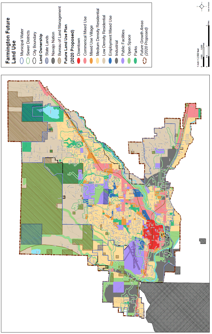
(Ord. No. 2022-1335, 1-25-22)
Sec. 13.4 - Traffic impact studies.
City of Farmington Requirements
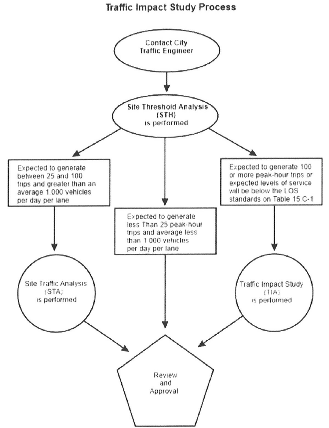
Figure 1: Traffic Impact Study Flow Chart
13.4.1 Traffic impact study (TIS). A TIS is a traffic study that determines the potential traffic impacts of a proposed traffic generator (i.e. proposed development). A complete analysis will include an estimation of future traffic with and without the proposed generator, analysis of the traffic impacts, and recommended roadway improvements that may be necessary to accommodate the expected traffic.
A.
Purpose. This standard provides uniform guidelines for conducting traffic impact studies for proposed development with access to a city street.
B.
Applicability. The community development director or designee shall determine applicability based on the following factors and considerations:
(1)
The City of Farmington has developed a TIS system based on the New Mexico Department of Transportation's (NMDOT) New Mexico Management Manual (NMAMM) Section 16, Chapter 6. The city's TIS system is used to determine the level of impact a proposed development has on an adjacent street. These impacts may result from the need for access along a street or because a proposed development is expected to increase traffic volumes on that particular street. The general types of traffic analysis are listed below:
a.
Site threshold assessment (STH) — a screening-level analysis to determine if additional traffic analysis is required. Consists of a one-page worksheet (STH Form).
b.
Site traffic analysis (STA) — a focused traffic study to assess site-specific impacts of a proposed development. Consists of an engineering evaluation and the preparation of a traffic study report.
c.
Traffic impact analysis (TIA) — a detailed impact analysis of all traffic operations, access and safety impacts within the prescribed study area for a proposed development. Consists of an engineering evaluation and the preparation study report.
13.4.2 Site threshold assessment (STH). A STH shall be required for all developing or redeveloping properties that directly or indirectly access a City of Farmington street. The requirements for the STH are described in the following subsections.
A.
The STH should examine existing street volumes and trip generation estimates to determine if additional traffic analysis is required. The city uses the NMAMM's STH form. The following information is needed to complete STH form:
(1)
A detailed description and location of the proposed development.
(2)
Existing daily traffic volumes for the adjacent roadway.
(3)
Trip generation estimates for the proposed development.
B.
The findings on this STH Form (Figure 2) will determine which direction the applicant should follow on the Figure 1 flowchart. From the results of the STH form, the applicant or their engineer would either proceed to a STA, a TIA or submit the results of the STH to the City Traffic Engineer or their designee for review.
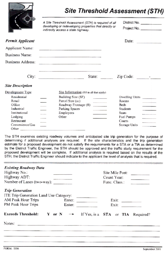
Figure 2: STH Form
C.
Trip generation.
(1)
The latest edition of the ITE Trip Generation Manual shall be used to identify trip generation rates. In cases where Trip Generation does not include trip rates for a specific land use category, includes only limited data; or, where local trip rates have been shown to differ from the ITE rates, other rates may be used with the approval of the city.
(2)
A trip generation table shall be prepared showing proposed land use, trip rates, and vehicle trips for daily and peak hour periods and appropriate traffic volume adjustments, if applicable. Site traffic generation shall be shown for daily, morning and evening peak hour periods. Adjustments made for "passer-by" and "mixed-use" traffic volumes shall follow the methodology outlined in the latest edition of the ITE Trip Generation Handbook. The "passer-by" traffic volume discount for commercial centers shall not exceed 25 percent unless approved by the city.
D.
Trip distribution and assignment.
(1)
Projected trip volume shall be distributed and added to the projected non-site traffic on the roadways and intersection(s) in the study area. The specific assumptions and data sources used in deriving trip distribution and assignment shall be documented in the report.
(2)
Future traffic volumes shall be estimated using information from transportation models, or applying an annual growth rate to the base-line traffic volumes. The future traffic volumes shall correlate to the project's specific timeframe. If the annual growth rate method is used, the city must give prior approval to the percentage used.
(3)
In addition, any nearby proposed or approved development projects shall be taken into consideration when forecasting future traffic volumes. The increase in traffic from proposed and approved developments, the application of an annual growth rate, or a combination of an annual growth rate and proposed and approved developments, shall be used to forecast the future traffic volumes.
(4)
The site-generated traffic shall be assigned to the street network in the study area based on the approved trip distribution percentages. The site traffic shall be combined with the forecast traffic volumes to show the total traffic conditions estimated at development completion. The total daily and peak period turning movement volumes for each traffic study intersection is required. In addition, the base-line volume with site-generated traffic added to the street network must also be shown. This amount will represent site-specific traffic impacts on existing conditions.
E.
Internal circulation.
(1)
Parking lot/on-site traffic circulation shall be in conformance with standards of practice as set forth by "Transportation and Land Development" (ITE, current edition).
13.4.3 Site traffic analysis (STA). The requirements for a STA are described in the following subsections. All STA's shall be sealed and signed by a registered/licensed New Mexico Professional Engineer.
A.
When is a STA required?
(1)
A STA is required when the results of a STH indicate that the proposed development is expected to generate between 25 and 100 peak-hour total trips, and the adjacent roadway currently has a daily traffic volume greater than an average of 1,000 vehicles per day per lane (vpdpl).
B.
When is a STA complete?
(1)
A STA is considered complete when a final traffic study report is signed and sealed by a registered/licensed New Mexico Professional Engineer, and is submitted to the city traffic engineer or their designee for review. Where the results of the STA indicate one of the following:
a.
The results indicate that the levels of service for the proposed access points and the adjacent intersections satisfy or are better than the applicable LOS standards (Table 15.C-1) and the city traffic engineer concurs with those findings, or
b.
The results of the STA indicate that improvements are required at the proposed access points and/or at the adjacent intersections, and a mitigation plan has been developed and approved by the city traffic engineer.
1.
UINT — Urban Interstate
2.
UPA — Urban Principal Arterial
3.
UMA — Urban Minor Arterial
4.
UCOL — Urban Collector
5.
RINT — Rural Interstate
6.
RPA — Rural Principal Arterial
7.
RMA — Rural Minor Arterial
8.
RCOL — Rural Collector
C.
Requirements for a STA:
(1)
Traffic analysis scoping meeting. A scoping meeting should be held between the permittee and the city traffic engineer, and any local jurisdiction that has authority over the proposed development. The meeting should be held when a preliminary site plan is available. It should be the responsibility of the permittee to schedule and prepare for the meeting. Specific aspects of the traffic analysis that should be discussed at the scoping meeting include:
a.
The proposed land use types and the development phasing;
b.
The number, type, and location of access points;
c.
The anticipated level of traffic analysis;
d.
The anticipated level of safety analysis;
e.
The study area limits;
f.
The analysis years and peak periods;
g.
The background traffic growth rate;
h.
The trip generation methodology;
i.
The basis for trip distribution;
j.
Other ongoing development activity;
k.
Pertinent programmed highway improvements;
l.
The traffic operations analysis techniques (e.g., isolated intersections versus signal systems);
m.
The documentation requirements; and,
n.
Any special conditions that should be considered.
(2)
STA study area: The STA study area should be defined at the traffic analysis scoping meeting. The study area for analysis should be proposed by the permittee and approved by the city traffic engineer in coordination with any local jurisdiction representatives that have authority over the proposed development. Guidelines for defining the study area for urban and rural conditions follow. When both urban and rural conditions exist within the study area, the guidelines for urban conditions should be used.
a.
Urban study areas: The STA study area for developments located on highways in access categories UPA, UMA and UCOL should include all site access points plus the first adjacent major intersection in each direction from the site.
b.
Rural study areas: The STA study area for developments located on highways in access categories RPA, RMA and RCOL should include all site access points plus the first adjacent intersection in each direction from the site expected to be used by development traffic to access the regional highway system, if any. Rural developments along isolated roadway segments, having no intersecting collector or higher classified roadways within five miles in either direction, should have the study area defined as the site access points.
(3)
Safety analysis: Three years of accident history should be reviewed for the major study area intersections. Intersection collision diagrams should be prepared showing the number of accidents, accident type, date and time of each accident, and accident severity. The intersection accident rate per million entering vehicles (acc/MEV) should be indicated on the collision diagram. The safety analysis should include a field review of the site.
(4)
Analysis years: The analysis years to be evaluated for site traffic analyses should be as follows:
a.
Existing year conditions.
b.
Implementation year without the proposed development.
c.
Implementation year with the proposed development.
(5)
The existing year is defined as the year the existing condition traffic counts are obtained. The implementation year should be defined as the calendar year that the proposed development is expected to commence operation.
(6)
Analysis peak periods: Traffic analysis should be performed for the AM peak hour and the PM peak hour of a typical weekday, or for the design hour associated with special traffic conditions provided by the city traffic engineer.
(7)
Trip generation: Trip generation estimates should be based on the type and intensity of the proposed land use, and should include estimates of daily and peak-hour travel. The ITE Trip Generation Manual (sub-section 9.F) should be used when the proposed land use is reasonably consistent with the land use categories and descriptions contained in the Trip Generation Manual. When the land use categories of the Trip Generation Manual clearly do not apply or the rates are not appropriate for a propose development, locally derived trip generation rates should be used. Trip generation rates that are based on local conditions should be developed according to the methodology described in the Trip Generation Manual.
(8)
Trip distribution and assignment: Trip distribution and assignment may be performed using manual techniques or a computer model. The trip distribution methodology should consider the area population, locations of similar land use, and travel distances. Trips should be assigned to the major street system based on logical routing patterns. The major street system includes streets classified as collectors and above. Trips may be assigned to the local street system when the local street provides direct access to the proposed development. Refer to Section 7 of the NMAMM for definitions of trip distribution and trip assignment.
(9)
Traffic projections: Implementation year traffic projections should include background traffic growth, trips generated by other known development projects in the study area, and trips generated by the proposed development, as appropriate. Other known developments should be considered built out or, if a phased development, built out according to the phasing schedule. Other known development projects within the study area should be included when:
a.
A development existed but was inactive when the existing condition traffic counts were collected, or
b.
A development was under construction at the time the existing condition traffic counts were collected, or
c.
A development opened since the existing condition traffic counts were collected, or
d.
A development was issued an access permit by the City of Farmington since the existing condition traffic counts were collected. (The city traffic engineer should inform the applicant of this condition at the scoping meeting.)
(10)
Intersection traffic analysis: Signalized and unsignalized intersections should be analyzed consistent with the current Highway Capacity Manual methodologies. The analyses may be performed using the current versions of the Highway Capacity Software, TeaPac, or other analysis packages approved by the NMSHTD Traffic Technical Support Section.
(11)
Measuring impacts: The STA should include an impact assessment for the intersections analyzed comparing implementation year conditions without and with the proposed development. Impacts should be measured based on the following comparisons:
a.
Isolated intersection performance statistics by approach movement and for the overall intersection.
b.
Magnitude and percent change in traffic volume by intersection approach movement.
(12)
Graphics: The STA documentation should contain a vicinity map showing all arterial and collector roadways within a reasonable influence area of the site, a study area map denoting the intersections included in the analysis, and a site plan that details the site access location(s) and internal circulation patterns. In addition to proposed land use details, the site plan should include dimensions to adjacent property boundaries and to adjacent access points along the site frontage, and should indicate locations of access points along the frontage on the opposite side of the roadway.
(13)
Documentation: All required site traffic analyses should include documentation in the form of a bound report. The STA documentation should discuss the following:
a.
Study Purpose;
b.
Development description;
c.
Study area land use description;
d.
Existing roadway and traffic conditions;
e.
Safety analysis (three-years);
f.
Background traffic growth;
g.
Trip generation, distribution and assignment;
h.
Traffic projections;
i.
Traffic analysis, including traffic signal warrants;
j.
Impact assessment;
k.
Proposed site circulation and parking plan;
l.
Access design specifications;
m.
Summary of deficiencies and proposed mitigation; and,
n.
Appended materials.
13.4.3 Traffic impact analysis (TIA). The purpose of a TIA is to conduct a comprehensive analysis of the transportation system that will provide access to proposed development site, including proposed access points, to identify potential short-term and long-term impacts on the roadway system. The requirements for a TIA are described in the following subsections. All traffic impact analyses shall be sealed and signed by a registered New Mexico Professional Engineer prior to the issuance of an access permit by the department.
A.
When is a TIA required? A TIA shall be conducted for each new development or property redevelopment along a roadway when:
(1)
The results of a STH indicate that the proposed development is expected to generate 100 or more peak-hour trips; or
(2)
The results of a STA indicate that expected levels of service will be below the LOS standards in Table 15.C-1, and a mitigation plan cannot be resolved between the city traffic engineer and the permittee to address identified deficiencies.
B.
When is a TIA complete? A TIA is considered complete when a final traffic study report, signed and sealed by a New Mexico registered professional engineer, is submitted to the city traffic engineer or their designee, and
(1)
The results of the TIA indicate that the levels of service for the proposed access points and the study area intersections satisfy or are better than the applicable LOS standards (Table 15.C-1) and the city traffic engineer or their designee concurs with those findings, or
(2)
The results of the TIA indicate that improvements are required at the proposed access points and/or at the study area intersections, and a mitigation plan has been developed and approved by the City Traffic Engineer or their designee.
C.
Requirements for conducting a TIA: The requirements for all traffic impact analyses follow. Additional requirements may be imposed by the city traffic engineer on a project-specific basis.
(1)
Traffic analysis scoping meeting: A scoping meeting should be held between the permittee and the city traffic engineer, and any local jurisdiction that has authority over the proposed development. The meeting should be held when a preliminary site plan is available. It should be the responsibility of the permittee to schedule and prepare for the scoping meeting. Specific aspects of the traffic analysis that should be discussed at the scoping meeting include:
a.
The proposed land use types and the development phasing;
b.
The number, type, and location of access points;
c.
The anticipated level of traffic analysis;
d.
The anticipated level of safety analysis;
e.
The study area limits;
f.
The analysis years and peak periods;
g.
The background traffic growth rate;
h.
The trip generation methodology;
i.
The basis for trip distribution;
j.
Other ongoing development activity;
k.
Pertinent programmed highway improvements;
l.
The traffic operations analysis techniques (e.g., isolated intersections versus signal systems);
m.
The documentation requirements; and,
n.
Any special conditions that should be considered.
(2)
TIA study area: The TIA study area should be defined based on the location and complexity of the proposed development, and should progressively expand with the complexity of proposed development. The TIA study area should be defined at the traffic analysis scoping meeting. The study area should be proposed by the permittee and approved by the city traffic engineer in coordination with any local jurisdiction representatives that have authority over the proposed development. Guidelines for defining the study area for urban and rural conditions follow. When both urban and rural conditions exist within the study area, the guidelines for urban conditions should be used.
a.
Urban study areas: The TIA study area for developments located on roadways in access categories UPA, UMA and UCOL should be determined based on the following guidelines for urban conditions. Typically, in urban areas, a TIA study area extending one mile from the proposed development site should be sufficient.
1.
The minimum urban study area size should include all site access points, the off-site intersections where a developer may reasonably be required to implement physical improvements, plus one additional major intersection in all directions. The study area may be expanded beyond the minimum to include intersections where high turning conflicts are anticipated.
2.
The study area for urban developments that propose access points within or adjacent to an interconnected traffic signal system, and that will require a progression analysis as part of a TIA, should include the intersections comprising the signal system. Where a signal system consists of more than three signalized intersections, the extent of the progression analysis should be determined by the city traffic engineer.
b.
Rural study areas: The TIA study area for developments located on roadways in Access Categories RPA, RMA and RCOL should be determined based on the following guidelines for rural conditions.
1.
Rural study areas should include all site access points, the roadway segments immediately adjacent to the access points and major intersections expected to be used by development traffic to access the regional highway system, if any.
2.
Rural developments along isolated roadway segments, having no intersecting collector or higher classified roadways within five miles in either direction and which generate 200 design hour trips or less, should have the study area defined as the site access points plus the roadway segments immediately adjacent to the assess points.
3.
Rural developments along isolated roadway segments, having no intersecting collector or higher classified roadways within five miles in either direction and which generate more than 200 design hour trips, should have the study area defined as the site access points plus the adjacent roadway segments and the first collector or higher classified cross-street intersection in each direction.
c.
Safety analysis: Three years of accident history should be reviewed for the major study area intersections. Intersection collision diagrams should be prepared showing the number of accidents, accident type, date and time of each accident, and accident severity. The intersection accident rate per million entering vehicles (acc/MEV) should be indicated on the collision diagram. The safety analysis should include a field review of the site.
d.
Non-phased development analysis years: The TIA analysis years to be evaluated for non-phased developments are defined below.
1.
Existing year conditions.
2.
Implementation year without the proposed development.
3.
Implementation year with the proposed development.
4.
Horizon year without the proposed development.
5.
The existing year should be defined as the year the existing condition traffic counts are obtained. The implementation year should be defined as the calendar year that the proposed development is expected to commence operation. The horizon year should be the implementation year plus ten years.
e.
Phased development analysis years: A phased development should require the same TIA analysis years as described in sub-paragraph D.1.d. (above), except the horizon year should be the year of full development plus ten years. Additionally, the horizon year should not be greater than the existing year plus 20 years. Depending on the type and scale of the proposed phased development, and considering study area conditions, additional implementation year analyses may be required. The additional analysis years should be identified at the TIA scoping meeting. The total number of analysis years for a phased development should not exceed four (i.e., there are currently two excluding existing conditions; no more than two additional analysis years may be required).
f.
Analysis peak periods: Traffic analysis should be performed for the AM peak hour and the PM peak hour of a typical weekday, or for the design hour associated with special traffic conditions. For future-year analyses beyond the initial implementation year analysis, the permittee may request that the future year analyses be performed only for the critical peak hour, identified based on the existing conditions analysis and the anticipated trip generation characteristics of the proposed development. The permittee should be prepared to make this request at the traffic analysis scoping meeting.
g.
Trip generation: Trip generation estimates should be based on the type and intensity of the proposed land use, and should include estimates of daily and peak-hour travel. The ITE Trip Generation Manual (Sub-Section 9.F) should be used when the proposed land use is reasonably consistent with the land use categories and descriptions contained in the Trip Generation Manual. When the land use categories of the Trip Generation Manual clearly do not apply or the rates are not appropriate for a proposed development, locally derived trip generation rates should be used. Trip generation rates that are based on local conditions should be developed according to the methodology described in the Trip Generation Manual.
h.
Trip distribution and assignment: Trip distribution and assignment may be performed using manual techniques or a computer model. The trip distribution methodology should consider the area population, locations of similar land use, and travel distances. Trips should be assigned to the major street system based on logical routing patterns. The major street system includes streets classified as collectors and above. Trips may be assigned to the local street system when the local street provides direct access to the proposed development. Refer to Section 7 (in the NMDOT Access Management Manual) for definitions of trip distribution and trip assignment.
i.
Traffic projections: Implementation year and horizon year traffic projections should include background traffic growth, trips generated by other known development projects in the study area, and trips generated by the proposed development, as appropriate. Other known developments should be considered built out or, if a phased development, built out according to the phasing schedule. Other known development projects within the study area should be included when:
1.
A development existed but was inactive when the existing condition traffic counts were collected, or
2.
A development was under construction at the time the existing condition traffic counts were collected, or
3.
A development opened since the existing condition traffic counts were collected, or
4.
A development was issued an access permit by the department since the existing condition traffic counts were collected. (The city traffic engineer should inform the applicant of this condition at the scoping meeting.)
j.
Intersection traffic analysis: Signalized and unsignalized intersections should be analyzed consistent with the current Highway Capacity Manual methodologies. Signalized intersections that are not part of a traffic signal system should be analyzed as isolated intersections. These analyses may be performed using the current versions of the Highway Capacity Software, TeaPac, or other analysis packages approved by the NMSHTD Traffic Technical Support Section. Signalized intersections that are part of a coordinated traffic signal system should require a progression analysis to be performed using TRANSYT-7F.
k.
Roadway segment traffic analysis: The capacity of specific roadway segments on two-lane highways and multi-lane highways should be evaluated when the traffic flow along the facility is not influenced by signalized intersection operations. This occurs where the average spacing of signalized intersections is greater than one signal installation per mile. Where a proposed access point is more than 500 feet from an isolated signalized intersection (i.e., there are no adjacent signalized intersections within one mile), roadway segment capacity analysis may be required. A roadway segment traffic analysis may be required for any traffic analysis when the directional volume passing the proposed access exceeds 1,200 vehicles per hour per lane.
l.
Measuring impacts: The analysis years of a TIA should include an impact assessment by intersection and/or roadway segment. The TIA should include a discussion of how the impacts were identified for a particular development. Impacts should be measured based on one or more of the following comparisons:
1.
Isolated intersection performance statistics without and with the proposed development.
2.
Roadway segment performance statistics without and with the proposed development.
3.
Traffic signal progression analysis results without and with the proposed development.
4.
Traffic volume comparison without and with the proposed development showing the magnitude and percent change in traffic volume by intersection approach movement.
m.
Graphics: The TIA documentation should contain a vicinity map showing all arterial and collector roadways within a reasonable influence area of the site, a study area map denoting the intersections included in the analysis, and a site plan that details the site access location(s) and internal circulation patterns. In addition to proposed land use details, the site plan should include dimensions to adjacent property boundaries and to adjacent access points along the site frontage, and should indicate locations of access points along the frontage on the opposite side of the highway.
n.
Documentation: All required traffic impact analyses shall include documentation in the form of a bound report. The TIA documentation should discuss the following:
1.
Study purpose;
2.
Development description;
3.
Study area land use description;
4.
Existing roadway and traffic conditions;
5.
Safety analysis (three-years);
6.
Background traffic growth;
7.
Trip generation, distribution and assignment;
8.
Traffic projections;
9.
Detailed traffic analysis for each analysis year, including traffic signal warrants;
10.
Impact assessment for each analysis year;
11.
Proposed site circulation and parking plan;
12.
On-site and off-site queue lengths;
13.
Non-motorized impacts;
14.
Access design specifications;
15.
Summary of deficiencies and proposed mitigation for each analysis year; and,
16.
Appended materials.
o.
Fair share cost analysis: Based on the impact assessment completed for the STA or TIA, contributory costs of identified improvements should be identified. In addition to implementing the necessary improvements within the roadway right-of-way at proposed site access points, the permittee shall be required to provide all or a portion of funding for mitigation of identified off-site impacts. The funding requirements shall be determined by the department through negotiations with the developer and the appropriate local government agency.
p.
Traffic study validity period: Approved traffic studies should remain valid for a period of one-year following approval of the driveway permit application, or as determined by the city traffic engineer or their designee. Below is a list of street classifications and their abbreviations:
1.
UINT — Urban interstate
2.
UPA — Urban principal arterial
3.
UMA — Urban minor arterial
4.
UCOL — Urban collector
5.
RINT — Rural interstate
6.
RPA — Rural principal arterial
7.
RMA — Rural minor arterial
8.
RCOL — Rural collector
13.4.3 Engineering qualifications. The STA and TIA shall be prepared under the direction of a professional engineer (civil) licensed to practice in the State of New Mexico with specific experience in traffic engineering and the preparation of STA and TIA reports.
(Ord. No. 2022-1335, 1-25-22)
Sec. 13.5 - Landscape guidelines for Farmington.
13.5.1 Landscape guidelines for Farmington. The natural landscape of Farmington is a high desert environment. There are two dominant native plant communities in Farmington, Piñon Juniper Woodland and Riparian Corridors. The Piñon Juniper Woodland occurs in the higher elevations, towards the northern part of town, and the Riparian Corridor occurs along the river corridor of the valley floor.
The limited amount of annual rainfall (eight inches—ten inches) received in Farmington means that most plants require some level of supplemental water. Landscapers are encouraged to use plants that are adapted to our environment (indigenous or native to similar climates of the world) and require low amounts of water. Given the characteristics of Farmington's natural environment, xeriscaping, or the use of water-efficient landscaping, is the most appropriate form of landscape design in a low-precipitation, high desert environment.
A xeriscape is not a "zero-scape." Xeriscaping emphasizes the use of plants adapted to dry conditions and is neither a barren nor a maintenance free landscape. Plants utilized in xeriscaping tend to be xeric, meaning that they require little supplemental water. (Xeros is Greek for dry.)
Xeriscaping utilizes several design principles to ensure that the created landscapes are suitable for the local climate and are water efficient. The principles applied in xeriscaping are good horticultural practices for our desert environment. The seven xeriscape principles are:
1.
Planning and design;
2.
Efficient irrigation systems;
3.
Use of mulch;
4.
Soil preparation;
5.
Appropriate turf;
6.
Water-efficient plant material; and
7.
Appropriate maintenance.
13.5.2 1. Planning and design. A good xeriscape landscape begins with good design and initial planning. Before you put the shovel to the ground, it is important to have a landscape plan. When creating a landscape plan, consider the physical characteristics of the site.
1.
What kind of soil is found on-site? Is it rocky, sandy, or made up of clays?
2.
What is the topography and how does the area drain? Is it flat or sloped? Are there natural drainages?
3.
Is there any existing vegetation or is it a vacant lot?
4.
What functions is the landscaping to serve? Will it be used as a play area, provide shade, or screen views?
Once the site and function of the landscaping is considered, select the right plant for the right place. When choosing plants, consider:
1.
Sun versus shade requirements.
2.
Height and spread of plant materials at maturity.
3.
The plant's function in the landscape, i.e. will it screen views or shade areas.
Also consider whether the desired plant has strong allergens or is an invasive species. Plants that have strong allergens should be used with caution. Several species of juniper are considered highly allergic. It is against the Farmington City Code (FCC) to plant the cotton bearing Cottonwood (FCC § 12-6-3). Seedless varieties are acceptable to plant. Russian olive and Salt Cedar are invasive species that have overpopulated areas along Farmington's river corridor. Invasive species out-compete native plant species, alter habitat, and affect ecosystem functions. Therefore, invasive species, such as Russian Olive and Salt Cedar, are discouraged as landscape plants.
Plants with thorns or stickers, such as pyracantha, are effective barrier plants but should not be used in areas of high traffic.
Do not plant trees under power lines, where branches will conflict with the lines.
Before you dig, verify all underground utility locations.
Group plants with similar water needs by dividing the landscape into zones of low, medium and high water uses (water zoning).
A.
High water use zone.
(1)
Typically these plants are the most colorful and have the greatest visual impact.
(2)
Limit plantings to areas near the building by the entry or around a patio.
(3)
Work's well on the northern and eastern sides of buildings where soils are moister or at runoff points, such as down spouts.
B.
Medium water use zone.
(1)
The transition zone or moderate water use areas should be planted farther away from the house or building.
(2)
Require less frequent watering, i.e. once a week or less, and usually less maintenance.
C.
Low water use zone.
(1)
Typically located the farthest away from the building.
(2)
Use plants that may require little or no supplemental water.
(3)
Select natives and other plants requiring little or no water for the low water use zones.
To help save on water costs, water can be harvested from roof down spouts into barrels and/or directed through swales or drainage areas within the landscape.
13.5.3 2. Irrigation. Proper and efficient irrigation saves water. Irrigation is required, even for drought tolerant plants, during the establishment period and periods of severe drought. Points to remember when designing an irrigation system are:
(1)
Separate water use zones for high, moderate and low water use plants.
(2)
Design irrigation systems with separate valves for each water zone.
(3)
Choose the appropriate type of sprinkler heads. Use spray heads for turf and bubblers, drip emitters, or micro-spray heads in shrub beds depending on the density of planting.
(4)
Irrigation systems may be manual or automatic. An automatic irrigation system saves time and provides better control of watering times.
Maintaining the irrigation system is also important. Repair all breaks in lines and clogged heads. Re-program the irrigation controller as the seasons change. Adjust spray heads to avoid over-spraying onto walks and walls. Do not allow irrigation water to run-off the landscaped area. (For more detailed information on how to set up an irrigation system, please see the irrigation guidelines section of the appendix.)
13.5.4 3. Mulching. Mulch is a protective layer applied over soils and may be composed of organic or inorganic material. Mulch provides a cover over the soil, reduces evaporation, helps maintain constant soil temperatures, controls erosion, and limits weeds which compete for water and nutrients.
A.
Organic mulches include bark, wood chips, cotton burr hulls, other nut shell byproducts, compost, grass clippings, and even newspaper. Organic mulches provide more than just the benefits mentioned above. They also improve soil conditions as they decompose, help keep soil structure loose, improve water infiltration, retain water, and allow for better root growth.
B.
Inorganic mulches include rock cobble, gravel, or crusher fines and synthetics such as rubber pellets. Rock mulches radiate heat and are better suited for truly xeric plants. Placing rock mulches work best in locations removed from a building. Ultimately, plants in rock mulches will shade the ground and cool the environment.
When using mulches:
(1)
Apply a three-inch to four-inch thick layer of mulch to effectively reduce weeds and retain moisture.
(2)
Avoid the use of organic mulch on slopes or high wind areas, as they will wash or blow away.
(3)
Do not apply organic mulches in direct contact with plants. Leave at least two inches of unmulched area around the plant stem to prevent disease and pests.
Plastic weed barriers can be used in a limited fashion where the soil must be kept dry, such as at the foundation of a house. However, landscape fabric is preferred, as it is permeable and allows air and water to pass to the plant roots.
13.5.5 4. Soil preparation. A critical aspect of any gardening function is soil preparation. It is important to test the soil first to determine what plants are adaptable to your yard and what amendments are required to improve the soil. Farmington soils are virtually devoid of organic matter and are typically fast-draining, sandy soils.
The size of the planting hole and the backfill used is an important part in amending soils. All planting holes should be at least twice the width of the container; however three times the width is preferred. Digging wide planting holes loosens the soil, which allows air, water, and nutrients to reach the roots.
The backfill around the plant should be amended with composted materials such as peat moss, composted wood shavings or yard waste. Adding compost improves the moisture holding capacity in sandy soils and improves the porosity in clay soils. Over time, the compost breaks down and forms humus that improves the structure of the soil. Be sure to thoroughly mix the native soil and compost before adding to the planting hole. The amended soil mixture should include no more than 50 percent compost. Plants requiring high to moderate water will require the most compost materials. Native plants require less composted material in the backfill (15—30 percent by volume).
Turf areas should be rototilled to a depth of four to six inches and amended with two cubic yards of compost per 1,000 square feet. Limit rototilling to areas being planted as disturbed areas make it easier for weed seeds to germinate.
13.5.6 5. Appropriate use of turf. While it requires more water and maintenance, turf has a place in xeriscape. Turf provides a playing surface for kids and pets, is an important cooling element, and reduces erosion and sun glare. However, turf should only be planted in an appropriate amount to meet specific needs. If turf is not serving a functional purpose, there are other low spreading ground covers can be used to provide a carpet of green that require less water and maintenance.
Proper selection turf used is important. If you need a turf for heavy use and a long growing season, a fescue or fescue-bluegrass mix is preferred. If it is a lighter use turf (mostly in the summer months) a warm season grass such as buffalograss, blue grama, or Bermuda grass is suggested.
13.5.7 6. Low water use plants. The principal concept behind xeriscaping is the use of low water use plants. There is a misconception that drought tolerant plants are unattractive. The truth is that there are many attractive plants with a variety of flower and foliage colors, fruit, fall color, fragrance, with different sizes, shapes and uses. Low water use plants are becoming more available in nurseries. A list of perennials, vines, shrubs, and trees are included in these guidelines. Please visit your local nursery for other drought tolerant plants that are suitable for the Farmington area.
13.5.8 7. Maintenance. Maintenance in the garden is just good horticultural practice, with design dictating the level of maintenance. Although most xeriscapes require less maintenance, a xersicape garden can be as labor intensive as you want it to be. The design dictates the level of maintenance. There is no such thing as a maintenance free garden. Plants will always require water and fertilizer, pest and weed control, and pruning or deadheading.
Sec. 13.6 - Irrigation guidelines for the City of Farmington.
Due to the limited annual rainfall received by the City of Farmington, supplemental irrigation is required to maintain plants in a healthy condition. A properly designed automatic irrigation system provides efficient application of water to the landscape. Below are suggested irrigation guidelines. These guidelines should not supersede a consultation with a qualified landscaping professional in designing an irrigation system.
13.6.1 Irrigation system design basics. Irrigation systems are designed with hydraulics in mind. Hydraulic principles such as gallons per minute, pounds per square inch, friction loss, velocity, and proper coverage all factor into the design of an irrigation system. These principles will be explained, as the components of an irrigation system are discussed.
13.6.2 Water meters. Most property owners will have a single water meter to service their building and site. Irrigation lines that tie into the water service downstream of the water meter may require tying into a copper line, which requires a licensed plumber to sweat weld a copper tee and an adapter for the irrigation line. For large scale landscape projects, a separate "irrigation only" water meter may be installed to prevent a monthly sewer assessment fee. If the property has the right to use water from an irrigation ditch, installation of a water meter is not required.
If an existing water meter is in place, the volume of water, or gallons per minute (GPM), is determined by the size of the existing water meter. If a new meter is being installed, the designer determines the meter size, based on an acceptable loss of pressure through the meter. Generally, four to eight pounds of pressure or pounds per square inch (PSI) may be allowed for meter loss. Pressure loss above this amount will either place undo stress on the meter or loose too much pressure for the system to operate correctly.
To help determine the amount of pressure loss expected given a particular meter size and GPM refer to the table on the following page.
Pressure is lost as water flows through components of an irrigation system. The amount of water that can flow through an irrigation component is determined by the size of the component and its acceptable pressure loss. It is critical that a proper level of pressure is maintained to operate an irrigation system effectively.
A.
Main lines. The main line is the supply line from the point of connection to the control valves. This portion of the line is under pressure at all times, with the exception of the winter months when the system should be shut off and drained. The main line is placed in the ground with a minimum of 18 inches of cover. Piping used for main lines should be a rigid, thick walled material, such as PVC (poly vinyl chloride) Schedule 40 or PVC Class 315. Main lines are sized based on acceptable friction loss, as recommended by the manufacturer. Pressure loss above the acceptable amount will either place undo stress on the main line or loose too much pressure for the system to operate correctly.
Friction loss is based on the velocity of the water running through the main line. Velocity is calculated in feet per second (FPS). Typically, the velocity in a line should not exceed five FPS. Irrigation manufacturers provide friction loss charts to help you determine the proper size of line. Main lines may be upsized to reduce the amount of pressure loss, if low pressure is a concern.
B.
Backflow devices.Once an irrigation connection has been made, a backflow device must be installed per Unified Plumbing Code standards. Contact the city's plumbing inspector to discuss the proper backflow device to be installed for your landscape. Backflow devices are sized based on an acceptable pressure loss, per the manufacturer's literature.
Smaller irrigation systems may use an atmospheric vacuum breaker (one per valve), placed 6" above the highest head. For larger irrigation systems, a single backflow device may be installed, such as a pressure vacuum breaker, a double check valve or a reduced pressure device. A pressure vacuum device is installed 6" above the highest head. A double check valve or reduced pressure device may be placed at any location on-site, irrespective of elevation. The Unified Plumbing Code requires a licensed contractor to install backflow devices.
C.
Control valves. Control valves turn on and off the water to individual circuits of sprinklers or drip emitters. Ideally, the control valves are wired to an irrigation controller, or timer, making the system automatic.
Control valves are sized based on the amount of acceptable friction loss. Typically, a control valve is sized one size smaller than the size of the largest lateral line downstream of the valve. Too little water running through an oversized valve may result in the control valve not opening properly. Pressure loss above the acceptable amount will either place undo stress on the control valve or loose too much pressure for the system to operate correctly.
Separate control valves should be used for turf versus shrub beds. Different types of turf heads, i.e. spray versus rotors or impacts, should be placed on separate valves, due to their differing rates of water application. Ideally, shaded areas, i.e. areas with north or east facing exposures, should be on separate control valves, because of the limited amount of sun they receive. Drip irrigation lines should also operate on their own special valves which come equipped with a pressure regulator and a filter.
D.
Irrigation controllers. An automatic irrigation system provides a great amount of flexibility in programming your system and reduces the time spent to maintain landscaping. Irrigation controllers automatically turn on and off your control valves as you have programmed them and will operate irrigation systems at any time of the day or night. Some controllers even offer multiple start times, which can be important in keeping a newly seeded lawn moist or keeping your landscape alive during a hot summer day. While most controllers require an electrical source, there are battery operated and solar powered controllers for remote locations where electricity is not readily available.
E.
Lateral lines. Lateral lines occur downstream of the control valves. The lateral lines are placed in the ground with a minimum of 12 inches of cover and usually are made of a rigid material, such as PVC Class 200 or greater. The sizing of lateral lines is also based upon acceptable friction loss. Pressure loss above the acceptable amount will either place undo stress on the lateral lines or loose too much pressure for the system to operate correctly.
F.
Poly pipe. Poly pipe is black, flexible tubing that comes in various sizes. Poly pipe may be used as lateral lines where flexibility is needed. Poly pipe may also be used as a swing joint at the base of a turf head. Again, friction loss needs to be taken into account when choosing the correct size of poly pipe to use.
G.
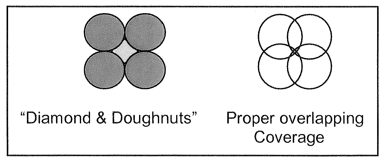
Turf heads. Turf heads come in a variety of configurations, with varying radii, patterns, PSI and GPM ratings. All turf heads should be pop-ups. Spray heads have the shortest spray radius and rotor heads, which are gear driven, and impact heads have larger spray radii. Turf heads with longer spray radii require greater water pressure and gallonage delivery.
Turf heads must be placed to provide head to head coverage, meaning the radius of one head must reach the base of the adjacent head. Improper coverage will result in dry spots with "diamond and doughnuts" or over watering to compensate for the lack of coverage. Refer to the manufacturer's product literature for the proper radius, gallons per minute and pressure performances.
H.
Shrub heads. Shrub heads also come in a variety of configurations, similar to the turf heads. Shrub beds with dense planting are best suited for spray, rotor or impact type heads. Shrub heads should also be laid out in a head to head coverage pattern. For lower density plantings, bubblers or drip irrigation may be installed. There are adjustable bubblers that can be fine tuned to a slow drip, as a quasi-drip system, without the need for filters, pressure regulators, and purge valve. Drip irrigation will be discussed in a separate section.
Shrub heads that occur along walkways or any area where people might walk should be pop-up type heads. This may require a 12-inch high pop to clear the adjacent shrubbery.
I.
Drain valves. Drain valves are installed to allow for the draining of an irrigation system and can be manual valves or automatic. Drain valves need to be installed at low points within the main line and lateral lines. If automatic drain valves are installed, they will open every time pressure in the line drops and drain the system after each irrigation cycle. If you don't effectively drain your system for the winter, you may be looking a serious repair bill.
Drain valves should not be installed upstream of a backflow device because the opening of the valve may allow for potential contaminants to enter the water supply.
J.
Drip irrigation. Drip irrigation provides a slow, even application of water that penetrates deep into the soil and promotes drought tolerance in plants. Drip irrigation systems operate at a rate of gallons per hour (GPH) versus the gallons per minute rate used with standard irrigation systems. Due to the differing rate of application, it is possible that your drip irrigation system will run for hours, not minutes. Drip irrigations systems also operate at lower pressures than standard irrigation. All other components of a drip system are similar to those used in a standard system. While drip irrigation systems require a higher level of maintenance, they are highly efficient in delivering water to plants and help lower water costs.
K.
Drip control valves. Like standard irrigation systems, a control valve is needed for drip systems. However, because of the small openings in the tubing and emitters, a drip system must have a filter and a pressure regulator, as well as a purge valve at the ends of the lines. Most drip irrigation manufacturers make a combination control valve, pressure regulator, and filter, to meet the needs of your drip system.
L.
Drip lines. Downstream of the drip control valve are the drip lines. The drip line is typically a one-half inch diameter black, flexible pipe that can be routed along the ground or buried. Use a UV resistant drip line if you place the drip line above ground.
Drip lines with emitter devices preset at even intervals are also available. This type of drip system requires rows of lines to provide uniform coverage in a shrub bed.
M.
Drip emitters. Drip emitters control the flow of water being delivered to the soil. Emitters come in a variety of shapes and sizes with single or multiple outlets and also vary in gallonage rates. A single outlet emitter typically is inserted into the one-half-inch drip line with a barbed fitting. It may also be placed on a shrub riser with and adapter. A multi-outlet emitter (six to eight outlets) usually is placed on a shrub riser with a tee or an ell on the drip line.
Micro-spray" heads for drip systems have relatively short radii and low gallonage rates. Often they are used similarly to standard spray heads.
N.
Drip tubing. Drip tubing is typically a one-quarter-inch diameter black, flexible tube that is run on the ground, from the emitter to the plant. Ideally, the end of the tubing is secured with a stake and closed with a bug cap.
O.
Purge valves. Even with a filter at the control valve, sediments have a way of clogging the drip system. Purge valves are ball valves placed at the ends of drip lines to allow for periodic flushing. In order to maintain proper functioning of a drip system, it is advised that drip lines are purged several times a year.
Sec. 13.7 - Retaining walls and slopes.
13.7.1 Guideline introduction. The City of Farmington will review retaining wall design for conformance with generally accepted design and construction standards. The City of Farmington assumes no responsibility or liability for the design, construction or long term integrity of the wall. Review and approval of plans by the city is required in order to obtain a building permit.
13.7.2 Definitions. The following definitions are used in this handout:
A.
Retaining wall. A landscaping technique intended to change the contour or grading of the lot.
B.
Exposed height. The exposed height is measured from grade level to the top of the wall at a given location.
C.
Problem soils. A soil type which may have a high water table, expansive clays, low weight bearing capacities, frost heave potential or other behavioral problems.
13.7.3 Overview of general requirements. Construction of any retaining wall with exposed height greater than one-foot six inches (18 inches) requires a building permit. Retaining walls with exposed heights of 36 inches or greater, or with a surcharge or a problem soil must be an engineered wall.
13.7.4 Zoning requirements. In addition to the structural review performed by building inspection, the development services department will review proposed retaining walls to ensure they meet all required setbacks and height restrictions regulated by the City of Farmington. Approval of setbacks and height requirements are completed prior to applying for a building permit.
The Community Development Department is located at 805 Municipal Drive, Farmington, NM, 87401. Please contact the Planning Division at (505) 599-1301 for further information.
13.7.5 Building permit application and approval requirements.
A.
A complete site plan, drawn to scale, showing:
(1)
Property boundaries;
(2)
Location of existing structures;
(3)
Location and dimensions of proposed retaining wall; and
(4)
Indicate wall elevations and exposed height.
B.
Approval signatures from the planning division.
C.
Payment of required permit fees.
D.
Approval by the building inspection department.
E.
Obtain building permit or permits.
13.7.6 Retaining wall design guidelines. The following guidelines are designed to assist in building structurally sound retaining walls and shorten the process to obtaining permits:
A.
Site specific conditions to consider include, but are not limited to:
(1)
Existing soil conditions at the wall location.
(2)
Topography.
(3)
Surface grade.
(4)
External pressures and surcharges.
B.
The City of Farmington recommends that retaining walls incorporate the following design principles:
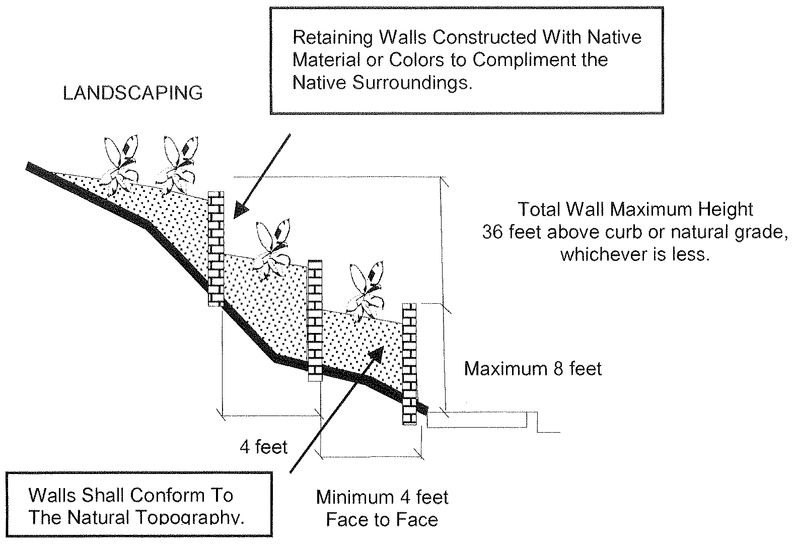
(1)
For each eight feet of vertical height, a four-foot horizontal offset should be provided.
(2)
Walls should conform to the topography of the site.
(3)
Walls with a change in alignment should incorporate the use of graduating steps rather than sharp corners to the greatest practical extent.
C.
Additionally, as stated in subsection 5.4.7A., materials utilized in the construction of retaining walls;
"Walls visible from public rights-of-way, within the frontyard setback(s), shall either incorporate the use of native materials or complement the native surroundings."
13.7.7 Slopes. When constructing a retaining wall along a slope, the following should be considered:
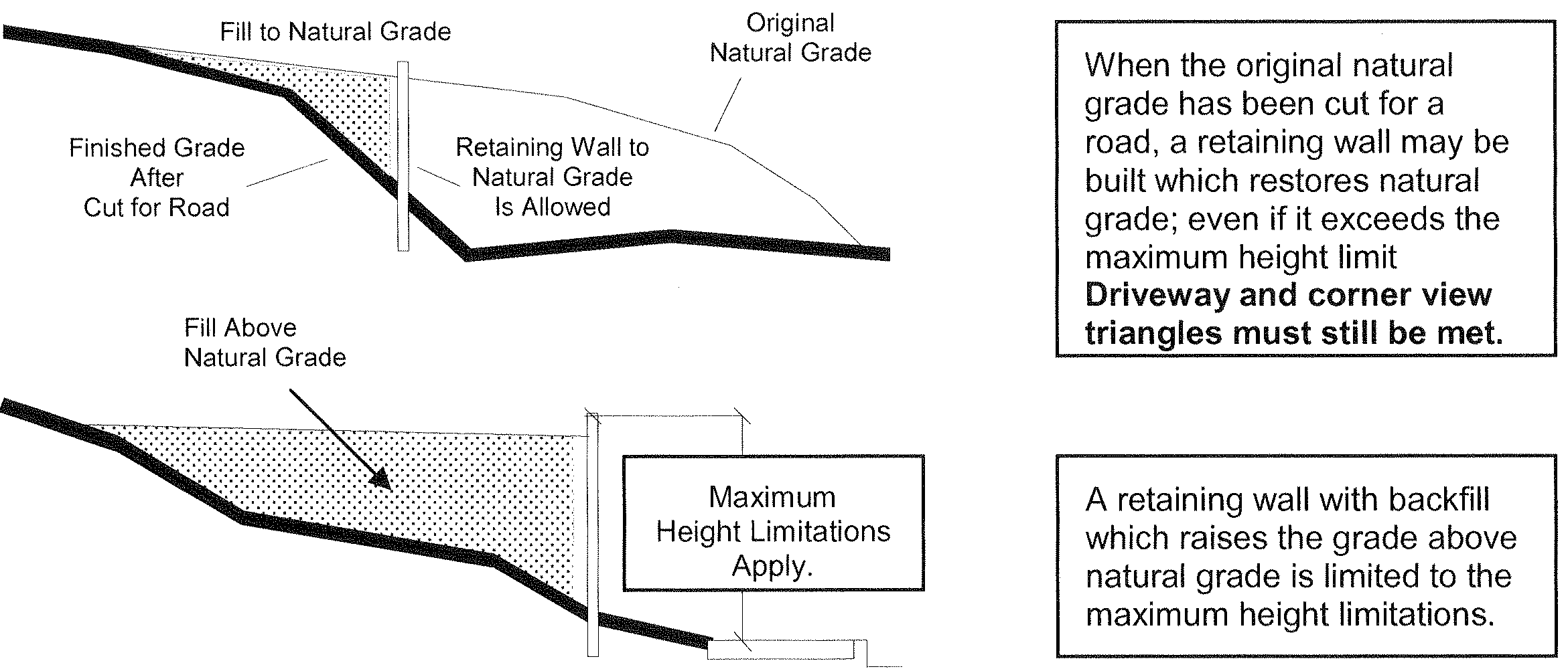
13.7.8 Public utility requirements. Call One Call at 1-800-321-2537 before excavating to ensure that the location of construction does not interfere with underground utility lines. One Call is a free service that marks the path of underground utilities on the property for those who are planning to excavate. Utility companies support One Call to prevent damage to their buried lines. If One Call is not contacted and damage occurs, you will be liable for all repair costs.