Slidell City Zoning Code
ARTICLE 10
SUBDIVISION REGULATIONS
Section 10.1.- Introductory provisions.
A.
Purpose. In order to ensure proper development and redevelopment in the City of Slidell, the subdivision of land should, through proper standards:
1.
Provide for adequate light, air, open spaces, drainage, transportation, public utilities; and
2.
Ensure the development and maintenance of a healthy, attractive community; and
3.
Conserve and protect both human and natural resources.
B.
Authority and effect. This article sets forth for the City of Slidell under the authority granted by the provisions of Act 139 of 1956 and R.S. 33:101—33:119, as amended:
1.
Minimum standards governing streets, utilities, and other required improvements.
2.
Minimum standards governing the preparation and filing of land subdivision plats and data to be submitted to the planning commission for approval.
3.
Proper coordination of future streets and their development with existing or planned streets.
4.
Penalties for the violation of the provisions of this article.
5.
Regulatory variations that may be approved by the planning commission coin accordance with the procedures set forth in article 4 of this UDC in certain cases or under certain conditions.
C.
Title. These regulations shall be known as the "city subdivision regulations" and may be so cited.
D.
Jurisdiction. The city subdivision regulations shall govern all subdivisions of land within the incorporated area of the City of Slidell, Louisiana. However, the provisions of these regulations shall not be applicable to plats of the subdivisions recorded as required by law and approved by the city council prior to the effective date of these regulations.
E.
Administration. The planning commission, upon approval of the mayor and city council may employ any staff, person or persons, or consultants to assist in the administration and coordination of these regulations. Final approval of plats and other data shall be the responsibility of the planning commission as prescribed by the law.
F.
Severability. If any section, clause, paragraph, provision, or portion of these regulations shall be held invalid or unconstitutional by any court of competent jurisdiction, such holdings shall not affect any other section, clause, paragraph, provision, or portion of these regulations.
G.Procedure. Subdivision requests will be processed in accordance with article 4 — Procedures of this UDC.
H.
Applicability. The regulations and development standards of this article shall apply to the following forms of land subdivision and redevelopment activities:
1.
The division of land into two or more tracts, lots, sites, or parcels.
2.
The dedication, vacation or reservation of any public or private easement through any tract of land regardless of the area involved, including those for use by public and private utility companies.
3.
The dedication or vacation of any street or alley through any tract of land regardless of the area involved.
4.
The substantial improvement of an existing development site, where upgrades to public infrastructure are required. In such cases, the extent of the upgrade shall be relative to the overall impact of the redevelopment request and approved by the director of planning. All such improvements must comply with the minimum standards in this article.
I.
Responsibility. In consideration of the acceptance by the City of Slidell and the assumption of the responsibility for maintaining the dedicated streets and public utilities construed therein, the developer/owner or owners of parcels of land, subdivision or parts of subdivisions shall construct at no expense to the city, the improvements required by this article according to the specifications of this UDC.
Section 10.2.1 - Lots and blocks, purpose and minimum standards.
A.
Purpose. This section addresses the quality, and sustainable design of lots, blocks, and access to best support future building sites and the movement of traffic and people throughout the city. The standards of this article seek to provide for predictable, uniform, and well maintained urban and suburban environments that are accessible, sustainable, and support the economic viability of building sites and developments that are functional, safe, and attractive; and a community character that conveys a positive, lasting impression on both residents and visitors.
B.
Minimum lot configuration and infrastructure requirements. All lots of record created or improved in the city must:
1.
Meet the minimum lot, area, width, yard, setback, and depth requirements in the zoning district where the lot is located as per article 6 of this UDC;
2.
Meet minimum general development and use standards associated with lot establishment or significant improvement as per articles 7 and 8 of this UDC;
3.
Have and maintain access to a public street (without having to cross another lot);
4.
Have access to drainage, sewer, fire prevention, and water services meeting the requirements of the Code of Ordinances or the UDC at the time of lot designation; and
5.
Front on and have ingress and egress by means of a public street or road.
C.
Lot development requirements.
1.
All single-family residential development must be platted and constructed with only one primary residential dwelling per lot or record.
2.
Adjacent and contiguous lots of record may be combined for building development only after review and approval by the planning commission.
3.
No structure may be erected across recorded lot lines unless the lots in question are resubdivided and such resubdivision is recorded with the clerk of court.
4.
Exceptions to this section include those developments customarily designed with shared ownership of structures and land in mind, including multi-tenant shopping centers, business complexes, and townhomes or duplexes provided all other requirements of this UDC are met.
Section 10.2.2 - Streets, minimum standards.
A.
New and improved public infrastructure. Developers or owners of a parcel of land, subdivision or part of a subdivision that requires the installation or improvement of public infrastructure shall be required to grade and improve streets and alleys and to install monuments, sewers, stormwater inlets, water mains, curbs, and sidewalks in accordance with this article.
B.
Minimum hard surface. All streets shall be paved with hard surface of asphalt concrete mix or concrete pavement as prescribed in this article.
C.
Minimum base classification. After preparation of the subgrade, the roadbed shall be surfaced with material required by local standards but must be no lower classification than eight inches soil cement base or approved equal.
D.
Wearing surface on paved streets. After an approved thoroughly compacted base has been established, three and one-half-inch asphalt concrete mix or better wearing surface shall be applied. Concrete paving shall provide six inches compacted subgrade and a minimum of six inches concrete pavement.
Section 10.2.3 - Street construction.
A.
Extent. These standards apply to the removal of existing materials and the construction of base course and concrete paving for the construction or alteration of a street in the city as part of an approved subdivision or development permit. In constructing improvements to the standards provided in this section, the developer or owner shall be responsible for all labor, materials, supervision, equipment and services necessary to complete construction according to approved plans, including leaving the site in a "broom clean" condition.
B.
Excavation and site preparation.
1.
The developer shall excavate the site as necessary to permit construction of an eight-inch minimum thickness sand base course.
2.
The developer shall remove and dispose of all materials in the location of the proposed pavement sections to a minimum depth of 14 inches from the grade of the proposed pavement.
3.
The developer shall compact the exposed surface to a minimum of six inches depth as follows:
a.
For cohesionless sands and gravels—100 percent of maximum modified AASHO density.
b.
For all other soils—90 percent of maximum modified AASHO density.
C.
Soil base course. The following standards are applicable to the process of placement and compaction of a base course, a minimum of six inches thick:
1.
Soil to be used for base course will be a well-graded soil meeting the following requirements:
a.
Maximum particle size: ¾ inches.
b.
Percent passing ¼ inch size: 85 percent maximum.
c.
Percent passing No. 200 sieve: 15 percent maximum.
d.
Plasticity index: 8 percent maximum.
3.
The developer shall compact the base course to a minimum of 100 percent of maximum modified AASHO density.
4.
Equipment. All equipment used shall be suitable for the purpose intended and shall be in good operating condition. The minimum equipment required to establish the base course shall be:
a.
A blade grader weighing not less than three tons and having a blade at least ten feet in length and a wheelbase of not less than 15 feet.
b.
Tractors with cleated tracks weighing not less than ten tons.
c.
Sheep's foot rollers of the multiple unit oscillating type with crawler tractor. Each unit of the drum shall consist of a drum provided with tamping feet not less than seven inches long and equipped with teeth cleaning devices. The roller shall weigh not less than 50 pounds per linear inch of drum length without ballast, and with the drums entirely filled with ballast the roller shall weigh not less than 50 percent more than when empty. The pressure per square inch of tamping area with one row of tamping feet supporting the roller, shall not be less than 110 pounds without ballast.
d.
The sheep's foot roller shall be of the size, shape and weight best suited to give the required densities in the materials being compacted. In general, sandy soils will require unit pressures of 50 to 100 pounds per square inch with tamping feet of ten to 12 square inch area. Sandy loams and light clays will require unit pressures of 100 to 150 pounds per square inch.
D.
Concrete pavement. At a minimum, the placement of a 4,000 psi test Portland concrete pavement, a minimum of eight inches thick, is required on major and collector streets and a minimum of six inches thick is required on minor streets. Such placement must meet all of the following standards below:
1.
No concrete shall be placed until the base has been approved by the city engineer or his/her designated inspector.
2.
Materials.
a.
Portland cement shall conform to ASTM C-150 Type 1, latest revision.
b.
Sand shall consist of clean, sound, durable grains, free from dust, dirt, clay or harmful substances.
c.
Coarse aggregate shall be of hard durable rock or gravel, free from shale or decomposed pieces. (ASTM C-33).
d.
Water used in mixing concrete shall be clean and free from deleterious amounts of acid, alkali or organic material.
e.
Water used in concrete shall be potable water fit for human consumption unless water of a lesser quality is approved in writing by the city engineer.
f.
Expansion joint filler shall be premolded, nonextruding type.
g.
Tie bars: Steel bars shall conform to the requirements of ASTM specification A-615, A-616 and A-617, latest revision.
h.
All tie bars shall be securely held in place by the use of spacers, wire chairs or other approved methods to maintain steel in the position shown on approved plans.
i.
Longitudinal center joints. As indicated on approved plans, the pavement shall be constructed with a longitudinal joint in the center of the pavement. This joint shall be formed by means of a metal strip of the gauge and form shown on the plans and may be either plain, painted or galvanized as shown on approved plans. The metal strips shall be not less than ten feet and not more than 15 feet in length made of one single strip of metal, and shall be held rigidly in place by suitable pins at least 12 inches long, driven vertically through punched holes in the joint. Except at all transverse joints where a gap of one inch must be provided, adjoining strips shall be lapped not less than two inches and securely fastened by means of the pins driven through matched holes in the splice or butt joints may be constructed if suitable clips approved by the city engineer are used. The spacing of the holes and the pins shall be in no case greater than shown on approved lans. Punched or cut holes shall be provided in the metal strip, spaced as shown on approved plans, to receive the transverse tie bars across the center joint. These bars shall be of length, size and installed as shown on approved plans.
j.
Expansion and contraction joints. Expansion and contraction joints shall be constructed using redwood board expansion fillers conforming to AASHO designation M90-42 Standard Specifications. "Starlug" load transfer and expansion and contraction devices as manufactured by Texas Foundries, Lufkin, Texas, shall be used, or an equal device approved by the department of engineering. The starlug and filler shall be a complete unit assembled and ready for setting in place.
k.
Joint sealing material. Material for pouring seal on expansion joints and for filling dummy joints shall be an asphalt filler conforming to the latest revision of AASHO Specifications M-18 Type A or an approved mastic filler.
l.
Curing agents. Curing agents shall be wet burlap, pending or white pigmented impervious membrane. The material shall be at least equal to "Hunt's" white pigment.
m.
Forms. Forms shall be of steel and shall have a depth equal to slab thickness. Form sections shall have a length of at least ten feet on tangents. On curves, shorter sections or wood forms may be used.
n.
Admixtures. Air-entraining and cement-dispersing agents such as possolith, as manufactured by Master Builders Company or equal will be permitted in concrete at the option of the developer provided the admixture meets with the approval of the city engineer. Only one brand will be permitted throughout the entire job. The product must be dispersed in liquid form, accurately measured and introduced into the mixture at the same time as the sand, gravel, cement and water are combined in the mix.
o.
Reinforcing steel. In the event reinforcing steel is required for concrete pavement, such reinforcement shall be designed by a professional engineer and approved by the city engineer. Reinforcing steel shall be new billet steel and meet the requirements of the ASTM designation: A-615-68, Grade 40 deformed bar, and subsequent revisions, for concrete reinforcement. The steel shall be stored in such a manner so as to be protected from mechanical injury and surface deterioration caused by exposure to conditions producing rust.
p.
Fiber reinforcing. All concrete pavements shall contain macro synthetic fiber reinforcement for temperature and shrinkage crack width control. This fiber will be used instead of highway mesh. This fiber shall be as follows:
i.
For all roadway pavements, Fibermesh 650, or approved equal, shall be applied throughout the concrete mixture. Macro synthetic fibers shall provide a minimum average residual strength per ASTM C 1399 of 162 psi at three pounds per cubic yard, and 216 psi at four pounds per cubic yard of concrete. Alternate products shall be preapproved by the city engineer in writing. Fibrillated and self-fibrillating fibers are specifically prohibited from use. Macro fiber dosage rate shall be:
(1)
Collector streets at four and one-half pounds per cubic yard of concrete.
(2)
Residential (minor streets) at three pounds per cubic yard of concrete.
ii.
All sidewalk and driveway pavement shall contain micro polypropylene fibers. These shall be applied to the concrete mixture at the rate of one and one-half pounds per cubic yard of concrete. Cellulose (treated or untreated), AR glass, nylon, and polyester fibers are specifically prohibited from use.
4.
Mixing and proportioning.
a.
Ready mix concrete may be used provided it conforms to the requirements set forth herein and ASTM Specification C-94, latest revision.
b.
Concrete shall be so proportioned as to give a minimum 28-day compressive strength of 4,000 psi. Water content shall not exceed the amount recommended by a testing laboratory and approved by the city engineer. Aggregates shall be batched by weight. Cement shall be measured by sacks or by weight and water shall be accurately measured by volume or weight. Slump to be no greater than five and a half inches.
c.
Water will not be added on the job.
d.
Only one brand of Portland cement shall be used throughout the entire job, unless specifically approved by the city engineer. In no event shall more than one brand be used in the pour of any one day.
5.
Before placing concrete all of the following conditions must be met or satisfied:
a.
Placing shall not be commenced until sufficient subgrade is prepared and forms set. Concrete shall be placed with minimum rehandling and in one layer. The concrete shall be sliced and spaded while being placed. Particular attention shall be given to vibrating adjacent to forms and joints. Over-vibration or manipulation causing segregation shall not be permitted.
b.
When forms have been securely set to grade, the base shall be tested as to cross section and elevations by means of template. The template shall be so constructed and operated to correctly indicate locations where the base does not conform the specified elevation and section. Low areas shall be brought to proper elevation by filling with approved material. Pavement shall not be placed on loose materials or a rutted base.
c.
The base shall be saturated with water the previous night or not less than six hours prior to the placing of concrete. If it subsequently becomes too dry, the subgrade shall be sprinkled, but the method of sprinkling shall not be such as to form mud or pools of water.
d.
Concrete shall not be placed on a frozen subgrade. No concrete shall be mixed while the air temperature is at or below 40 degrees Fahrenheit. Concrete shall not be placed unless the air temperature is at least 40 degrees Fahrenheit and rising. No materials containing frost or lumps of hardened materials shall be used. No concrete shall be placed around manholes or other structures until they have been brought to the required grade and alignment.
e.
The roadway pavement shall be of the size and shape set forth in approved plans including the integral curb, and consist of one course of Portland cement concrete with the addition of joints, dowels, etc., as called for in approved plans.
f.
Form work. Forms shall be so constructed and placed as to resist, without springing or settlement, the pressures of the concrete. When set to grade and stakes in place, the maximum deviation of the top surface from a straight line shall not exceed one-eighth inch and one-fourth inch in ten feet for the up-standing leg.
g.
Forms shall be cleaned and oiled each time they are used.
h.
Site mixing. The mixing of concrete shall be done in a batch mixer of approved type and size to ensure a uniform distribution of the materials throughout the mass, so that the mixture is uniform and homogenous. The equipment at the mixing plant shall be so constructed that all materials (including the water, admixture of fine sand, if used) entering the drum can be accurately proportioned and be under control. The entire batch shall be discharged before recharging. The volume of the mixed material per batch shall not exceed the manufacturer's rated capacity of the mixer. The mixing of each batch shall continue for the periods indicated below during which time the drum shall rotate at a peripheral speed of about 200 feet per minute. The mixing periods shall be measured from the time when all of the materials are in the mixer drum. Mixing time shall be as set out in the subsections below.
i.
For mixers of a capacity of one cubic yard or less: 1½ minutes.
ii.
For mixers of capacities larger than one cubic yard: The time of mixing shall be increased 15 seconds for each additional one-half cubic yard capacity or fraction thereof.
i.
The mixer shall be thoroughly checked and calibrated before beginning operations and during mixing operations or at any time deemed necessary by the engineer. Equipment not in good operating condition shall not be used.
j.
Central plant batching. Batching of materials in the desired proportions may be accomplished at a central plant when so approved by the city engineer. When approved, the batching plant shall include batcher bins, either of the stationary or mobile types, with separate compartments for fine and coarse aggregates, each compartment designed to discharge freely and efficiently into the weighing hopper or hoppers. The scales for weighing aggregates shall be either the horizontal or the springless dial types, designed of rugged construction as an integral unit of the batching plant with a maximum allowable error of one-half percent of the net load and with significant gradation down to two pounds. The developer shall maintain the equipment in good condition and adjustment and shall provide for accurate operation. If, for any reason, equipment previously approved becomes unsatisfactory, it shall be repaired or replaced before proceeding with the work.
k.
Aggregates shall be transmitted from the batching plant to the mixer in batch boxes, vehicle bodies or other containers of adequate capacity and construction to properly carry the volume required. Cement in original shipping packages may be transported on the top of the aggregates, each batch containing the number of bags required by the "job mix." Batches shall be delivered to the mixer separately and intact, and each batch container shall be dumped cleanly into the mixer without loss of cement or mixing or spilling of material. Bulk cement may be used if necessary precautions to prevent loss in transit are taken. All vehicles carrying loose cement must be covered during transit with tarpaulin.
l.
Mixing shall be accomplished as specified above for site mixing.
m.
Central plant mixing. The use of a central mixing plant will not be permitted unless specifically approved by the city engineer in writing. When such approval is given the concrete shall be mixed to such consistency that the hauling will cause no segregation of the constituent materials. The method of storing and hauling and equipment used shall be subject to the approval of the city engineer. Vehicles used to transport the mixed concrete shall be equipped with suitable devices for slowly agitating the concrete during transit and for delivery of the concrete in an unsegregated condition of uniform consistency. Any vehicle load showing nonuniform consistency on arrival will be subject to rejection.
n.
Transit mixing. Transit mixing will be permitted, provided that the requirements of ASTM specification C-94, latest edition are met.
6.
Placing concrete. Concrete shall not be placed until base has been conditioned as hereinabove specified. Base shall be moistened in advance of concreting but shall not be muddy or excessively wet. The concrete shall be mixed in quantities required for immediate use and shall be deposited on the base to the required depth and width of the pavement section in successive batches and in a continuous operation without the use of intermediate forms or bulkheads between joints. While being placed, the concrete shall be spaded and compacted with suitable tools so that the formation of voids or honeycomb pockets is prevented. The concrete shall be especially well spaded and tamped against the forms and along all joints.
a.
Concrete will not be dropped onto the base from such a height as to damage forms. The bucket or chute will be as close to the base as possible when the concrete is released.
b.
At the end of a day's placement, or in the case of unavoidable interruption of more than a 30-minute period, a transverse joint shall be placed at the point of work stoppage; provided that the section on which the work has been suspended shall be not less than ten feet in length; sections less than ten feet in length shall be removed from the subgrade, and the removed concrete shall be disposed of from the site.
7.
Working and finishing concrete. In working and finishing concrete in the city, the developer shall follow the sequence of operations: First, "the strike-off and consolidation;" second, "longitudinal floating and removal of laitance;" followed by "straight edging," "belting" and final finish "brooming."
a.
Strike-off and consolidation. The concrete shall be distributed or spread as soon as placed. A mechanical concrete spreader may be used. The concrete shall then be struck off and screeded by vibration or means approved by the developer's engineer. The striking off and screeding shall conform to the existing crown and cross section determined before removal of the existing pavement and shall be performed at such elevation slightly above grade that, when properly consolidated and finished, the surface of the pavement will be at the original elevation and free from porous areas.
b.
Hand methods of strike-off and consolidation. Concrete, as soon as placed, shall be struck-off and screeded to the original crown and cross section determined before removal of the existing pavement and to such elevation above grade that when consolidated and finished, the surface of the pavement shall be at the grade elevation. A strike-off original template constructed to produce the pavement surface cross section indicated on approved plans shall be provided for this work. It shall be rigidly constructed to retain its shape. In making the strike-off above mentioned, the template shall be moved always in the direction in which the work is progressing and so manipulated that neither end is raised from the side forms during the striking-off process.
c.
Longitudinal floating. After the concrete has been struck off and consolidated it shall be further smoothed and consolidated by means of a longitudinal float, using one of the following methods.
i.
Hand method. The hand-operated longitudinal float shall not be less than three feet in length and six inches in width, properly stiffened to prevent flexibility and warping. In this operation, a longitudinal float, operated from boot bridges resting on the side forms and spanning but not touching the concrete shall be worked with a sawing method motion, while held in a floating position parallel to the road centerline, and passing gradually from one side of the pavement to the other. Movement ahead along the centerline of the pavement shall be in successive advance of not more than one-half the length of the float. Any excessive water or soupy material shall be wasted over the side forms on each pass.
ii.
Mechanical method. The mechanical longitudinal floats shall be of a design approved by the developer's engineer, and shall be in good working condition. The tracks from which the float operates shall be accurately adjusted to the required crown. The float shall be accurately adjusted and coordinated with the adjustments of the transverse finishing machine so that a small amount of mortar is carried ahead of the float at all times. The forward speed shall be adjusted so that the float will lap the distance specified by the developer's engineer on each transverse trip. The float shall pass over each area of pavement at least two times, but excessive operation over a given area will not be permitted. Any excess water or soupy material shall be wasted over the side forms on each pass.
d.
Brooming. As soon as the surplus water, if any, has risen to the surface, the pavement shall be given a broom finish. The broom shall be drawn from the center to each edge of the pavement with adjacent strokes slightly overlapping. The brooming operation shall be so executed that the corrugations produced in the surface will be uniform in appearance and not more than 1/16 of an inch in depth. Brooming shall be completed before the concrete is in such condition that the surface will be torn or unduly roughened by the operation. The surface thus finished shall be free from rough and porous area, irregularities and depressions, resulting from improper handling of the broom. Brooms shall be of the quality, size and construction and be so operated as to produce a surface finish meeting the approval of the city engineer. Subject to satisfactory results and approval of the city Engineer, the developer will be permitted to substitute mechanical brooming in lieu of the manual brooming as herein described.
e.
Edging. After brooming has been completed, but before the concrete has taken its initial set, the edges of the slab shall be carefully finished with an edger of the radius required by approved plans, and the pavement edge shall be left smooth and true to line.
8.
Curing. Curing shall be by an approved moist curing method or by spraying with an approved curing compound. Materials and methods used shall retain, after 72 hours, at least 90 percent of the original water in the mix, when tested by ASTM C-156. Curing will follow immediately after brooming.
a.
Curing compounds.
i.
Impervious membrane curing compound. Curing compound shall be of a consistency suitable for spraying, shall be relatively nontoxic, and shall satisfactorily adhere to a horizontal surface of damp concrete when applied immediately causing the disappearance of surface water. The resultant film shall be continuous, uniform, free from pinholes, moisture, impermeable and shall not react with the components of concrete. The compound shall be supplied with a fugitive dye, which shall show no indication of its use in 15 days. When the compound is applied to test specimens, at a rate of coverage recommended by the manufacturer for one application, the specimens shall not lose more than the maximum amount of moisture as follows:
(1)
At 24 hours two and one-half percent.
(2)
At 72 hours five and one-half percent.
(3)
At seven days seven percent.
ii.
The compound shall be dry to touch on a damp horizontal concrete surface in not more than two hours at a temperature of 75 degrees Fahrenheit when applied at a rate of coverage recommended by the manufacturer.
b.
Membrane curing compound pigmented. Curing compound shall comply with all requirements hereinabove contained and in addition, shall meet the following specific requirements.
i.
The compound shall be a white pigmented type.
ii.
The compound when applied to a new concrete surface at the specified coverage, shall provide a uniform white appearance and shall effectively obscure the original color of concrete. After the compound has dried it shall have an apparent daylight reflectance of not less than 60 as determined by Method 612 of Federal Specifications TT-P-14LA. The compound shall have a hiding power of not less than eight square feet per gallon when tested in a manner as stated in Part 3, Division 11, Paragraph 5.21 of the Standard Specifications for Roads and Bridges, State of Louisiana, Department of Highways, July 1955.
c.
Regardless of the coverage per drum of compound stated by the compound manufacturer, the concrete surface will be satisfactorily covered.
9.
Form removal.
a.
Form removal shall be carefully done without damage to green concrete and not before 12 hours after placing. Holes, voids, or honeycombs shall be filled with 1:2 mortal and floated smooth. Expansion joints shall be cut free of concrete. Edges shall be protected by earth, planking or membrane curing compound pigmented as specified above immediately after form removal.
10.
Joints. Joints shall be cleaned of foreign matter and filled with an asphalt filler to within one-quarter inch of the top.
11.
Cleanup. Prior to acceptance of the work by the city engineer, the developer shall clean all dirt, trash or superfluous matter from the finished roadway.
12.
Testing.
a.
Two cylinders for each 50 cubic yards of concrete in place, or for each 100 linear feet of street placed or from each day's placement (whichever shall be similar) plus two beams for every 200 cubic yards of concrete placed or from each day's pour (whichever shall be smaller) shall be taken in accordance with ASTM C-31.
b.
One of each pair of cylinders or beams taken shall be tested at seven days and one at 28 days.
c.
In addition to the tests hereinabove mentioned, if evidence of faulty workmanship exists, violation of specifications, or likelihood of the use of faulty material, tests may be required, which may be made under the direction of the city engineer. The costs of such tests shall be paid for by the developer if the developer is required to replace any concrete or if the concrete is inferior to that specified.
13.
Inspection.
a.
Final inspection shall be made in accordance with the general conditions. The pavement shall be clean.
b.
Opening for traffic. The developer has full responsibility for his pavement until it is accepted by the city engineer. The developer must place suitable barricades of sufficient size and weight to prevent easy removal, across all accesses to the unaccepted pavement.
c.
The use of unaccepted pavement by the developer, any of his subcontractors, the public or the city before it conforms with the strength requirements of paragraph d below is prohibited without written permission of the city and the violation of same either through direct intent on the part of the developer or by others due to the failure of the developer to sufficiently prevent access, may prevent final acceptance by the city engineer.
d.
The pavement can be opened to all traffic when the results of the 28-day cylinder tests show the concrete has the required strength. The pavement can be opened to light traffic when test results indicate 75 percent or 3,000 psi of the desired strength has been obtained and then only upon approval of the city engineer.
e.
The city reserves the right to open the pavement to traffic or to prohibit the opening to traffic at an age other than specified above, if, in the opinion of the city engineer, physical conditions warrant.
f.
The same strength requirements govern concrete made with Type III cement.
g.
Concrete curbs shall be cast integrally with the pavement in conformity with the appropriate detail shown on approved plans. If cast integrally, the strike-off template must be designed to accommodate the curb, and the pavement must be painted with a neat cement paste of six gallons of water to one sack of cement immediately before casting the curb. Concrete for curbs must conform to the specifications above for pavements.
14.
Drilled dowels.
a.
Where the existing doweling or hardware remaining in a portion of pavement is not satisfactory to the city engineer, he/she shall direct its removal and replacement with drilled and grouted dowels.
b.
Removal of existing hardware shall be at the option of the city engineer and shall be accomplished without destruction of pavement to remain. Damage to pavement to remain will be repaired by the developer in a manner acceptable to the city engineer, and at the expense of the developer.
c.
Dowels shall be #4 reinforcing bar of any steel listed in ACI 318-71, installed as shown on the plans, or an equivalent item specifically manufactured for the purpose and acceptable to the city engineer.
d.
Drilling shall produce a hole three-quarters of an inch in diameter and at least 12 inches deep in the existing pavement, centered in the thickness of the existing slab.
e.
Dowels shall be grouted into the drilling hole with a neat-cement grout to six gallons of water to one sack of cement. The hole shall be filled with grout and the dowel inserted in such a manner as to ensure that no voids exist.
f.
Where required, dowels shall be placed on 12-inch centers.
Section 10.2.4 - Driveways.
A.
Concrete driveways shall be constructed of such lengths and widths as shown on approved plans.
B.
All standard driveways shall be a minimum [of] six inches in thickness. Driveways shall be formed of Portland cement concrete of the same materials, mixed in an approved manner, placed and have the same compressive strength and cured in accordance with street construction standards in section 10.2.3.
C.
In the case that driveways are to be constructed where no roadway pavement is to be installed, the driveway concrete shall meet the requirements of the concrete for combined concrete curb and gutter bottom and/or concrete curb.
D.
Expansion joints shall be provided where shown on standard plans or as may be otherwise directed and made in the following manner. Premoulded joint filler, one-half inch in thickness and of a depth of one-half inch less than the thickness of the driveway, shall be placed perpendicular to the surface.
E.
The subgrade on which the driveways are to rest, shall be thoroughly rolled or tamped so as to be uniformly compressed and solidified. The finished grade shall be smooth, even well sealed and exactly parallel to the finished surface of the driveway.
Section 10.2.5 - Sidewalks.
A.
Applicability. Sidewalks shall be constructed in all subdivisions and at all building sites with the following exceptions:
1.
Sidewalks are not required in residential neighborhoods if there is not an existing sidewalk within 300 feet on the same side of the street.
2.
Along state highways the developer must submit a permit for construction of sidewalks to the Louisiana Department of Transportation and Development section 62 (LA DOTD) for approval. If the LA DOTD section 62 denies the permit, then sidewalks are not required.
3.
If a street is in a St. Tammany Parish public right-of-way, a permit must be submitted to St. Tammany Parish Engineering Department for approval. If the St. Tammany Parish Department of Engineering denies the permit, then sidewalks are not required.
B.
Minimum width requirements for sidewalk area zones, as defined in article 2 of this UDC. While this article includes minimum standards, the city encourages developers/property owners/contractors to provide wider sidewalks when practical, especially in high pedestrian traffic areas.
1.
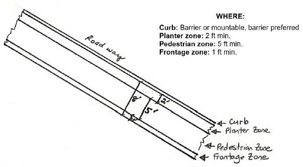
Planter zone area: 2 feet.
2.
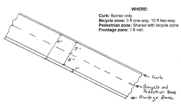
Bicycle zone, one-way bicycling: 5 feet.
3.
Bicycle zone, two-way bicycling: 10 feet.
4.
Pedestrian zone with a planter zone: 5 feet.
5.
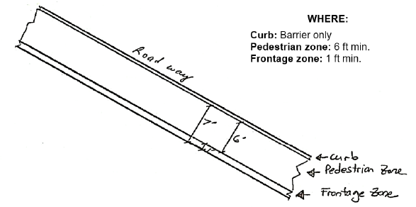
Pedestrian zone with no planter zone: 6 feet.
6.
Frontage zone: 1 foot.
7.
Shared use path: 10 feet.
C.
Curbing. Barrier/vertical curbs are required when there is no separation between the roadway and the pedestrian zone or bicycle zone. When there is a planter zone the curb can be either barrier/vertical or mountable/sloped.
D.
Approved sidewalk designs. A developer may select and construct sidewalks in the city in accordance with the designs provided in this section, provided construction meets the minimum standards in this article.
1.
Option 1. Sidewalk with planter zone as detailed in Figure 10.2.5-1.
Figure 10.2.5-1. Pre-Approved Design for Sidewalk with Planter Zone
2.
Option 2. Sidewalk with no planter zone as detailed in Figure 10.2.5-2.
Figure 10.2.5-2. Pre-Approved Design for Sidewalk with No Planter Zone
3.
Option 3. Shared use path as detailed in Figure 10.2.5-3 Pre-Approved Design for Sidewalk with No Planter Zone. The shared use path is intended to accommodate both pedestrian and bicycles. The minimum width must be broken into two, five-foot wide lanes, one in each direction. The divider can be delineated by paint alone. If there is a raised surface (see definitions in article 2 of this UDC), its width must be added to the minimum ten-foot path width to accommodate wheelchair use.
Figure 10.2.5-3. Pre-Approved Design for Sidewalk with No Planter Zone
E.
Sidewalk materials and construction. Sidewalks shall be constructed of four-inch-thick concrete. Additional technical specifications for constructing sidewalks are provided in this subsection.
1.
Concrete sidewalks shall be constructed with the same materials, having the same compressive strength, placed and cured in the same manner as the concrete in the roadway slab. They shall be four feet in width and fixed at such elevations as may be specified on the plans or as directed by the city engineer and shall have a minimum thickness of four inches.
2.
In preparing the subgrade on which the concrete sidewalk will be placed, all soft and spongy places shall be removed and all depressions filled with suitable materials which shall be thoroughly compacted in layers not exceeding six inches in thickness. The subgrade shall be thoroughly tamped until it is brought to a firm unyielding surface. It shall have slope in conformity with the slope of the finished surface of the concrete sidewalk.
3.
After the concrete has been placed in accordance with paragraph 5 it will be brought to the established grade by means of a strike board, and it will then be worked with a wood float in a manner which will thoroughly compact it and provide a surface free from depressions or irregularities of any kind. Excessive working shall be avoided. In no case shall dry cement and sand be sprinkled on the surface. The surface edges of all slabs shall be rounded to a radius of one-half inch.
4.
Concrete sidewalk shall be divided into blocks of such dimensions as the city engineer may designate by means of a jointer or groover. Transverse expansion joints shall be made at intervals of about 32 feet so as to separate the sidewalk into slabs or sections. These expansion joints shall extend from the surface to the bottom of the sidewalk, be one-half inch in width and filled with joint filler. The joint filler shall extend from the bottom of the sidewalk to approximately one-half inch below the surface of it.
5.
All expansion joints shall be carefully made so as to be truly perpendicular to the surface of the sidewalk and at right angles to the edge of same. The surface of the concrete adjacent to expansion joints shall be finished with a wood float which is divided through the center and which will permit finishing on both sides of the joint at the same time. An expansion joint shall also be provided adjacent to solid walls of masonry, behind curbs at intersections and at footlaps. Where posts or poles fall within the limit of the sidewalk an expansion joint not less than one-half inch in width shall be placed around said posts or poles and filled with joint filler. In the case of expansion joints adjacent to masonry walls, at footlaps and around posts or poles, the joint filler shall not extend above the surface of the sidewalk and any excess joint filler that so protrudes shall be cut off and made flush with the sidewalk.
6.
As soon as the finished work has hardened sufficiently to prevent damage, the developer shall provide adequate curing. The curing medium used shall be the same as stated in "Portland Cement Concrete Roadway Pavement." The concrete surface must not be damaged or pitted by rain drops and the contractor shall provide and use, where necessary, sufficient protection to completely cover all sections of freshly placed concrete. The developer shall erect and maintain suitable barriers to protect the walk from traffic, and any section damaged from traffic or other causes, shall be repaired or replaced by the developer at his own expense, in a manner satisfactory to the city engineer. The walk shall not be opened to traffic until the prescribed curing period has expired.
F.
Additional standards and requirements.
1.
Sidewalks will be free of obstruction. Where sidewalks must shift to avoid obstructions the shift will be gradual so that pedestrians and bicyclists have ample time to adjust.
2.
Sidewalk grade will not exceed five percent.
3.
Sidewalk cross slope will not exceed two percent.
4.
Whenever a sidewalk transitions to street level or a driveway crossing the connection will be smooth so as to not provide a trip hazard.
5.
Use Louisiana Department of Transportation standard plans for curb ramps, sidewalk pedestrian facilities, intersection layouts, and detectable warnings.
G.
Waiver. The city may administratively approve sidewalk alternations to accommodate unique location restrictions on a case-by-case basis upon request for a waiver and approval of the department of planning and city engineer in accordance with article 4 of this UDC.
Section 10.3 - Traffic Impact Analysis.
A.
Purpose and intent. The purpose and intent of this section is to protect the health, safety and welfare of the citizens and visitors of the City of Slidell by ensuring the provision of safe and adequate roadway facilities. The provisions of this section establish requirements for transportation studies that provide information on traffic projected to be generated by proposed developments. It is the further intent of this section to establish requirements for the identification of any potential traffic operational problems or concerns, as well as potential solutions to such problems or concerns.
B.
When required. A traffic impact analysis shall be required for each development when the following traffic peak hour trips are exceeded.
1.
If the Institute of Transportation Engineers Trip Generation Manual indicates that the proposed development shall generate an equal or a less amount of traffic than the existing development, then no traffic impact analysis shall be required.
2.
If the Institute of Transportation Engineers Trip Generation Manual indicates that the proposed development shall generate more traffic than 50 peak hour trips, then the following shall apply:
a.
Limited traffic impact analysis. If the proposed development shall generate greater than 50 and less than 150 peak hour trips, either in AM or PM, the developer shall submit a limited traffic impact analysis that shall include the following:
i.
The proposed trip generation and distribution.
ii.
The source of the information submitted, for example the Institute of Transportation Engineers Trip Generation Manual. If a source other than the Institute of Transportation Engineers Trip Generation Manual is used, then a comparison between the source used and the Institute of Transportation Engineers Trip Generation Manual shall be submitted.
iii.
An analysis of the ingress and egress of the development in relation to the level of service on the adjacent roadway system.
iv.
The study shall include recommendations for any roadway or intersection improvements to maintain the existing level of service.
v.
An analysis of the roadway capacity, whether existing or proposed, on all roadway links abutting the proposed development site and identification of roadway and/or intersection improvements necessary in order to maintain the existing level of service.
vi.
An analysis of the capacity and of the level of service of the nearest signalized intersection in each direction from the major entrances into the development.
b.
Comprehensive traffic impact analysis. If the proposed development shall generate greater than 150 peak hour trips, either AM or PM, the developer shall submit a Comprehensive Traffic Impact Analysis that shall include the following:
i.
All requirements of a i, ii, iii, iv, v, and vi above.
ii.
Graphs, maps and charts showing how the traffic shall be distributed onto the existing transportation network within a minimum of one-half mile of the proposed development, and an analysis of the capacity and of the level of service of each roadway link and intersection within this area for both existing and proposed conditions.
iii.
Recommendations as to how any deficiencies determined by the analysis shall be resolved, including signalization and roadway geometrics.
C.
Procedures.
1.
Pre-approval of the study firm. Prior to submission of the traffic impact analysis, the developer shall submit the qualifications of the planner and of the engineer that shall perform the traffic impact analysis to the departments of planning and engineering for approval.
2.
The principal in charge of the traffic impact analysis shall, at a minimum, be a licensed engineer with a specialization in traffic study, or shall be a licensed engineer with a specialization in traffic engineering, and shall have at least five years of experience in traffic engineering, or, shall be a planner with an American Institute of Certified Planners certification and shall have at least five years of experience in transportation planning.
3.
No traffic impact analysis shall be accepted by the departments of planning or engineering unless a proposal of the traffic impact analysis, an outline of the proposed traffic impact analysis, and the required professional qualifications are first presented to the departments of planning and engineering for review and approval.
D.
Traffic impact analysis contents and format. A traffic impact analysis shall contain, but not be limited to, the following:
1.
A map of the specific study area.
2.
Existing land uses within 500 feet of the proposed development from any point of contact with the property line.
3.
Trip generation.
4.
Trip distribution: one-year, two-year, three-year traffic assignments.
5.
Capacity analysis on adjacent and integral roadways.
6.
Accident incident data within one-half mile of site.
7.
Traffic assignments and capacity analysis.
8.
Existing data on signalization affecting the site, including geometrics of the signal, type signal, and any other pertinent data that shall affect the upgrading of the signals.
9.
Recommendations and findings.
E.
Final approval. The approval of the director of planning and of the city engineer of the traffic impact analysis shall be required prior to final approval of the development and prior to the issuance of building permits.
F.
Actions based on traffic impact analysis. When a proposed development subject to the traffic impact analysis requirements of this section demonstrates that the proposed development shall overburden the roadway system or cause a reduction in service of affected roadway below the adopted level of service, an applicant may be required by the departments of planning and engineering to modify the development proposal to minimize the identified traffic related impacts. Modifications to applications for a development may include, but shall not be limited to:
1.
A reduction in the projected vehicle trips per day;
2.
Dedication of additional rights-of-way;
3.
Rerouting of traffic and proposed access points serving the proposed project, subdivision or development;
4.
Participation in funding transportation off-site facilities, including signals and intersection improvements deemed necessary by the traffic impact analysis; or
5.
Other actions deemed necessary as demonstrated by the traffic impact analysis and deemed appropriate by the departments of planning and engineering.
Section 10.4.1 - Sewerage system construction requirements.
A.
General and administrative requirements.
1.
Approval required. No sewer main or other collection works shall be installed in the city, except in accordance with plans and specifications that have been approved by the city engineer.
2.
City obligations. Approval of the plans and specifications by the city engineer does not bind the city to perform any work, move or repair any facility, or provide traffic control or any other service.
3.
Guarantee. All sewer constructed by or for a developer and delivered to the city is required to be guaranteed by the developer against defects in materials and workmanship for a period of one year from the date of acceptance by the city.
4.
Connection to city sewer systems. A sanitary sewerage collection system shall be installed in such a manner as to adequately serve all lots with connections to the city sewerage system. Sewer connection shall comply with the regulations of the state board of health. The system shall be constructed under the approval and supervision of the St. Tammany Parish Health Unit and the City Engineer of Slidell. All sanitary sewer systems shall conform to the following requirements:
a.
Minimum pipe size allowed shall be eight inches in diameter.
b.
Gradients, pipe type, location, and type of manholes, characteristics of lift stations and treatment facilities shall be approved by the City Engineer of Slidell and the Louisiana State Board of Health prior to construction.
c.
Sanitary manholes shall be spaced at intervals not to exceed 350 feet at each junction or change in alignment.
d.
Each lot within the subdivision shall be connected to the system.
5.
Capacity and flow. All sanitary sewers shall be designed to carry peak rates of flow of 150 gallons per capita per day and/or as prescribed by the Louisiana State Board of Health. Sewers shall be constructed to meet infiltration standards as set forth by the state board of health.
6.
Fees. A subdivision developer who connects a subdivision sewer system to the city sewer system shall pay to the city a fee to be determined by the city at the time of connection to the sewer system, which fee will offset the cost to the city of expanding city facilities to adequately handle the increased demand on the city system.
B.
General construction requirements, common to all sewer installation.
1.
Trenching.
a.
Trench width below the top of the pipe shall be limited to the outside diameter of the pipe, straight or sloping sides of greater width are permissible.
b.
Trench widths in excess of those allowed by paragraph a may be used only with the specific written approval of the city engineer.
2.
Dewatering. Sewers shall be installed in surface-dry trenches. Sump pumping (in impervious or slightly pervious soils) and well points (in pervious soils) will be used as necessary to achieve and maintain the surface-dry condition. Failure to eliminate standing water and to expose the trench bottom will be cause for rejections of the construction by the city. When joint materials or support materials require "curing," no water will be permitted in the trench until these materials have set.
3.
Sheeting and shoring.
a.
Sheeting which extends below 18 inches above the top of the pipe shall be left in place.
b.
Sheeting may be cut off at or above 18 inches above the top of the pipe and must be cut off at or below two feet below the finished grade.
4.
Bedding.
a.
As a minimum, bedding will conform to Class C, "shaped bottom" as shown on Page 212, ASCE Manual No. 37, 1969. Where the soil appears different from the typical soil of the project, especially if it appears inadequate for support, the unsuitable material will be removed and replaced with a clean well-compacted granular material and the bedding will conform to Class C, "granular bedding" as shown in the same manual on the same page. Where the city engineer or his authorized representative finds the original trench bottom soil to be "unsuitable," this determination is binding and requires use of the "granular bedding."
b.
Nothing in this paragraph shall be construed to relieve the design engineer of responsibility for load analysis and bedding determination for the type of pipe selected, soil conditions, and applied loads.
5.
Pipe laying.
a.
All sewer lines shall be laid to lines and grades shown on plans approved by the city engineer. Bell and spigot pipe shall be installed with bell upgrade. Before being set in place, each length of pipe shall be thoroughly cleaned, free of earth, or foreign material.
b.
Each pipe shall be laid to form a close joint with the adjoining pipe sections having a continuous invert to the established line and grade. When sewer pipes are laid between manholes or other structures, a complete circle of light shall be visible from the pipe ends.
c.
Raising the sewer pipe to grade by ramming or tamping of earth and bedding material will not be permitted. Upon proper bedding of the pipe, the opening under its bell shall be properly filled in a manner such as not to disturb its position or joint. At points where work is temporarily suspended all open ends of pipe shall be securely sealed to prevent entrance of water, earth or other substances.
6.
Jacking and boring.
a.
Jacked or bored installations are permissible in general, however, the details of the operation require the approval of the city engineer. A drawing showing the guide or alignment apparatus, jacking equipment, and backstop together with the pipe manufacturer's document giving recommendations for this type of installation, will be submitted, together with any other information required by the city engineer. The field installation must also be approved by the city engineer before beginning operations.
b.
The city engineer's approval of the method and installation does not relieve the developer or contractor of responsibility for achieving the required line and grade.
c.
Jacking and boring may be used to install a lining, with the sewer main subsequently grouted in place, provided that the design has been approved in accordance with this article and section 4.16 of this UDC and the installation is approved in accordance with subsection 10.4.1.E.6.a. above.
7.
Wyes, tees and service connections.
a.
All wye branches, tees and other special fittings shall be installed at locations indicated on plans approved by the city engineer. Each wye shall be provided with a 45-degree bend properly connected to the branch. In cuts of eight feet or more, riser connections shall be provided with a tee having a six-inch branch in a vertical plane. A six-inch riser with double branch fitting set to proper elevation for service connections shall be constructed for the tee branch. Each connection will be recorded by marking its location at the curb.
b.
In unstable soils, the foundations for wyes and tees shall be a timber platform having vertically driven timbers to develop bearing for the masonry, the pipe fitting and the backfill.
c.
Service connection lines shall be installed from the sewer line branches or risers to the property line at a grade of not less than one-eighth inch per foot. Service connection lines will be a minimum of three inches in diameter, and be placed not more than four and one-half feet below finished grade. The line shall be true to line and grade, with all future connection openings being sealed tight against the entrance of water, earth or any other material until such time as the permanent connection at the property is made. Cleanout will be molded into 18 inches × 18 inches × four inches concrete slabs and clearly marked and shall be to sidewalk grade abutting sidewalk on property side.
8.
Manholes.
a.
Manholes shall be constructed at locations shown on the plans. An approved cast iron frame and cover shall be provided and installed with the top of the cover flush with the finished grade or at another elevation specified on the plans.
b.
Manholes for sewers less than 24 inches in diameter will have concrete interior bottoms and will be watertight for the full height. In general, all lines joining the manhole will enter at the bottom. Bottoms will have U-shaped channels of width and depth at least equal to the incoming lines leading to outgoing lines. Where a change in direction occurs, the lines should be brought in off-center as necessary to provide the largest possible radius to the curved channel, which is done by placing the ends of the outer channel side on opposite ends of a manhole diameter. The remaining area of the bottom will be shaped as a flat bench having a slope of one-half inch per foot towards a channel.
c.
Where pipe entry at the general elevation of the bottom cannot be achieved, the following requirements apply:
i.
If the pipe invert is less than 24 inches above the outfall invert, no drop inlet is required, but a channel in the manhole bottom is required. The channel will have dimensions as though the pipe entered at the bottom.
ii.
If the pipe invert is more than 24 inches above the outfall invert, a drop inlet is required. Where a drop inlet is required, an interior drop as shown in Figure 33 (right side) of ASCE Manual 37 (1969) is preferred.
d.
Manholes for sewers over 24 inches in diameter must be detailed on the plans and approved by the city engineer.
e.
No steps will be installed in manholes.
9.
Backfilling.
a.
When the trench is backfilled with soil from the original excavation, the soil must be hand-placed and compacted to 90 percent of maximum standard proctor density to a level 12 inches above the pipe. Special care must be taken to ensure placement and compaction beneath the pipe haunches and around the sides of the pipe. Soil will be placed in lifts not more than six inches thick before compaction.
b.
Where select materials are to be used for the backfill, the material properties and proposed placement specification will be submitted to the city engineer for approval.
c.
All material used for backfill will be free of roots, timber, trash or other deleterious material. Excess soil will be mounded as necessary to prevent a depression from forming due to subsequent consolidation.
d.
Trench sections under roadways and driveways will be backfilled in six-inch uncompacted thickness lifts, compacted to 90 percent of maximum standard proctor density to the surface or subgrade for pavement structure construction.
10.
Site restoration.
a.
In general, all surfaces damaged will be restored to a condition equivalent to that existing before the work began, including areas near, but not on, the sewer alignment and areas damaged by traffic rerouted by the contractor (or as a result of his operations).
b.
Earth surfaces will be restored to original grade or slightly mounded, with no obstruction to drainage or hazard to any person.
c.
Shell surfaces shall be restored with salvaged material or shell of the same type as the original surfacing after the backfill has been thoroughly consolidated over the trench. The replaced surfacing shall be smooth and free of foreign material.
d.
Concrete or asphalt surfacing will be replaced by similar construction of sound design and good workmanship as appropriate for the usage, regardless of the quality of the work removed. This Code and standard specifications will be followed in the design and construction, both of which must be approved by the city engineer.
e.
All other public works in the way of the construction will be left unharmed or replaced by similar construction of sound design and workmanship.
F.
Materials permitted and special construction requirements for each.
1.
Sewer pipe and appurtenances.
a.
Cast and ductile iron. Cast and ductile iron pipe and appurtenances may be used for gravity and pressure sewers. Materials and installation must conform to the following:
i.
Pipe and fittings must conform to one or more of the following:
AWWA C101, Thickness Design of Cast Iron Pipe
AWWA C106, Cast Iron Pipe Centrifugally Cast in Metal Molds, for Water or Other Liquids
AWWA C108, Cast Iron Pipe Centrifugally Cast in Sand-Lined Molds, for Water or Other Liquids
AWWA C110, Gray Iron and Ductile Iron Fittings, two-inch through 48-inch, for Water and Other Liquids
AWWA C150, Thickness Design of Ductile Iron Pipe
AWWA C151, Ductile Iron Pipe, Centrifugally Cast, in Metal Molds or Sand lined Molds for Water or Other Liquids
ii.
Linings and coatings. All cast and ductile iron pipe used in sewer must have an interior lining and an exterior conforming to the following specifications, unless approval of a different protection system has been obtained from the city engineer:
AWWA C104, Cement Mortar Lining for Cast Iron and Ductile Iron Pipe and Fittings for Water
AWWA C105, Polyethylene Encasement for Gray and Ductile Cast Iron Piping for Water and Other Liquids
iii.
Joints. Joints shall conform to the provisions of AWWA C111, Rubber Gasket Joints for Cast Iron and Ductile Iron Pressure Pipe and Fittings.
iv.
Installation. Installation will be in accordance with the manufacturer's recommendations, the recommendations of the "Handbook of Cast Iron Pipe" (Cast Iron Pipe Research Assn. Chicago, IL.), and good engineering practice. Conflicts will be referred to the city engineer for resolution.
b.
Plastic. Solid wall plastic pipe and appurtenances conforming to the following specifications may be used for gravity and pressure sewers. Truss pipe consisting of inner and outer walls connected by webs and having the voids filled with lightweight concrete or similar filler, is not allowed.
i.
Pipe and fittings. Pipe and fittings shall conform to ASTM Specification 3034, Specification for Type PSM Poly (Vinyl Chloride) (PVC) Sewer Pipe and Fittings, with dimensions conforming to "extra heavy" with a standard diameter ratio (SDR) of 35 as described in that specification, and shall be colored green.
ii.
Jointing. Joints on service connections of six inches diameter or less may be solvent-weld using cement conforming to ASTM Specification D2564 and socket dimensions acceptable to the city engineer. All joints on mains and on pipes over six inches in diameter will use elastomeric gaskets conforming to ASTM Specification D1869, C361 or C443.
iii.
Installation. Installation will conform to the provisions of ASTM Specification D2321, Underground Installation of Flexible Thermoplastic Sewer Pipe.
c.
Concrete. Reinforced and nonreinforced concrete pipe and appurtenances may be used for gravity and pressure sewers in accordance with the following requirements:
i.
Gravity sewers.
(1)
Concrete pipe conforming to one of the following specifications may be used for gravity sewers:
(a)
ASTM Specification C14, Specification for Concrete Sewer, Storm Drain and Culvert Pipe
(b)
ASTM Specification C76, Specification for Reinforced Concrete Culvert, Storm Drain and Sewer Pipe
(c)
ASTM Specification C506, Specification for Reinforced Concrete Arch Culvert, Storm Drain and Sewer Pipe
(d)
ASTM Specification C507, Specification for Reinforced Concrete Elliptical Culvert, Storm Drain and Sewer Pipe
(e)
ASTM Specification C655, Specification for Reinforced Concrete D-Load Culvert, Storm Drain and Sewer Pipe
(f)
In addition, pipe permitted for pressure sewers will be permitted for gravity sewers.
(2)
Joints in concrete pipe used for gravity sewers must be packed and sealed with a cement mortar, a preformed mastic gasket, or a trowel applied mastic compound in a procedure acceptable to the city engineer. In addition, any joint sealing method acceptable for pressure sewers may be used for gravity sewer.
ii.
Pressure sewers.
(1)
Concrete pipe conforming to ASTM Specification C361, Reinforced Concrete Low-Head Pressure Pipe, may be used for pressure sewers with maximum heads as indicated in the specification.
(2)
Joints in concrete pipe used for pressure sewers will conform to ASTM Specification C443, Joints for Circular Concrete Sewer and Culvert Pipe, with Rubber Gaskets.
(3)
Use of materials specified in this section does not relieve the engineer of responsibility for matching materials and methods to the hydrostatic head condition to be encountered. Other materials, methods and documentation supporting their adequacy will be submitted to the city engineer for approval.
2.
Manholes and junction boxes.
a.
Brick masonry.
i.
Brick used in the construction of manholes or other appurtenances for sanitary sewers will conform to the requirements of ASTM Specification C32, Specification for Sewer and Manhole Brick (made from clay or shale).
ii.
Mortars used shall be equivalent to Type N mortar as described in ASTM Specification C270. The city engineer will determine "equivalency."
iii.
Bricks must be laid in full, close-shoved joints or mortar at least one-quarter inch thick at the narrowest end and not more than one-half inch thick at the widest end. No spalls or bats will be allowed, except for shaping around openings and connections. In the event any brick is moved or a joint is broken during the brick laying, the brick shall be taken up, the mortar thoroughly cleaned from the brick, the bed, and the joints, and the brick relaid in fresh mortar. Bricks colder than 45 degrees Fahrenheit will not be used. Manholes must be at least eight inches thick above eight feet from the surface, and 12 inches thick below eight feet from the surface.
iv.
Inside and outside surfaces of the manhole shall be plastered with a layer of mortar not less than one-half inch thick. The completed brick masonry shall be protected and kept moist for at least 48 hours from completion. In freezing weather, the masonry shall be maintained above 45 degrees Fahrenheit for the same period.
b.
Precast concrete.
i.
Precast concrete manhole sections conforming to ASTM Specification C478, Specification for Precast, Reinforced Concrete Manhole Sections, may be used.
ii.
Joints between sections and at pipe openings shall be sealed in a manner similar to that for gravity sewers, and acceptable to the city engineer.
c.
Precast or preformed manholes of fiberglass or other suitable materials may be used with the approval of the city engineer. Manufacturer's documentation showing specifications and performance must be submitted.
i.
Manholes shall be not more than 350 feet apart.
3.
Lift stations.
a.
The following outlines the type of pumps and electrical controls to be installed at new sewage lift stations and old sewage lift stations to be renovated. The city prefers and feels it will be beneficial in maintaining the lift stations, if the pumps and electrical controls are standardized as much as possible. Therefore, it is recommending Gorman-Rupp (direct drive) trash pumps with U.S. electric motors, Healy-Ruff electrical control panels with suspended roto-float direct acting float switches (or comparable float switches) when a two-pump alternating system is used. When a single pump situation arises, a Gorman-Rupp (direct drive) pump with a mechanical float switch may be used.
i.
Belt-driven pumps, compact package units, and air bubbler systems for the electrical controls are not permitted. Any electric motor or electrical control panel to be exposed to the weather or sewer water will be drip proof enclosure for the motor and watertight panel box for the electrical starter. The use of submersible pumps is not permitted without approval of the city engineer.
b.
Electrical services.
i.
All services to be overhead, if possible, secured to the pumphouse or to a stationary pole. These poles are to be creosoted or pressure treated. Rigid conduit is to be used for the stack. The entire entrance is to be bonded and grounded, including the EMT covering the ground wire. If it is not possible for the service to be overhead, then rigid conduit (sized according to the gauge of wire and number of conductors) buried at a minimum of 36 inches from top of the grade is required. The length of the underground service is not to exceed 50 feet.
c.
Interior wiring.
i.
Rigid conduit is to be used from the motor starter panel to the motor pot head. Watertight flexible conduit can be used not to exceed 18 inches from the end of the conduit to the motor pot head. All wiring which controls the float bulbs is to be placed in rigid conduit to a point entering the wet well.
ii.
One 110V receptacle with a gfi breaker is required as well as proper 110V lighting. This receptacle circuit as well as the lighting circuit is to be placed in EMT.
iii.
All conduit, both motor circuits and lighting circuits, will be bonded and grounded and will be properly anchored.
iv.
All wire will be copper, stranded, TW or THW and sized according to the ampere load.
v.
All exposed lightbulbs to have guards, if these guards are metal, they will be bonded and grounded.
d.
Piping.
i.
All piping inside lift stations will be flanged cast iron or threaded iron pipe.
ii.
Section side. Going into wet well a combination (y and one-eighth bend) with plug in top will be used.
iii.
Discharge side. On each pump there will be a check valve and a gate valve. The hookup will all be long sweep fittings.
iv.
All hanging pipe will be properly supported and braced. The developer has the option of constructing a pumphouse or an open all-weather station.
e.
All pumphouses will be 20 feet by 20 feet, constructed of brick on a six-inch thick slab of 2,500 psi concrete. The house will be ventilated, have a round manhole cover over wet well, have a four-foot metal door and fresh water supply with a hose bib.
f.
All-weather station.
i.
All-weather stations will be constructed on a 20-foot by 20-foot concrete slab. The slab will be six inches thick, using 2,500 psi concrete.
ii.
A round manhole will be constructed over the wet well and there will be a fresh water tap with a hose bib.
iii.
The lift station will be enclosed by a fence, preferably chain link, but it is permissible to use wood.
G.
Inspection and testing.
1.
Inspection.
a.
Developers and contractors building sewer intended for city acceptance shall make the site and all materials available and accessible to the city engineer and his representative(s) at all times from the approval of plans or any authorization to proceed through city acceptance of the work.
b.
Developers and contractors shall demonstrate the establishment of line and grade for the city engineer, normally by advising the job inspector when basic surveying is to be done. Upon request, the contractor will provide copies of surveying field notes substantiating the initial grade establishment.
c.
Developers and contractors will provide manufacturers certificates showing compliance of materials with standard specifications cited in this "City of Slidell Standard Specification," or otherwise approved by the city engineer.
2.
Testing. All sewers constructed for city acceptance will be tested by the developer or contractor under the supervision of the city engineer as follows:
a.
Infiltration-exfiltration test. Where the groundwater table is more than four feet above the average invert of the sewer being tested, or less than four feet below the average ground surface, an infiltration test will be conducted. Where the groundwater table is not within the limits above, an exfiltration test will be conducted. Use of the alternative test or both tests may be required by the city engineer to demonstrate satisfactory performance for acceptance.
i.
Infiltration tests. The developer or contractor shall provide and install a V-notched wire at the outlet end of the section under test. Alternative measuring devices may be used with the approval of the city engineer. The measuring devices may be used with the approval of the city engineer. The inlet end of the section under test shall be plugged watertight. The test shall continue for at least four hours with accurate logs of flow information kept for the full period. Both the average flow for the test period and any flow rate observed for more than one-hour total time during the test must not exceed 500 gallons per inch of sewer pipe diameter per mile of sewer per day.
ii.
Exfiltration tests. The developer or contractor will plug the ends of the section under test tight. The sewer will then be filled with water to a level four feet above the highest point of sewer invert or four feet above the average groundwater table, whichever is higher, or to the bottom of the manhole cover frame. After a reasonable time for absorption in masonry and joints, the test shall commence. Water will be added to maintain a constant level in the sewer. The added water shall be accurately measured. The test shall continue for at least four hours with accurate logs of water addition being kept for the full test period. The average water addition required to maintain a constant level must not exceed 600 gallons per inch of sewer pipe diameter per mile of sewer per day.
iii.
Where the infiltration or exfiltration exceeds the established limits, the sewer will not be accepted by the city until remedial measures have been taken and the results of subsequent tests are within the established limits.
b.
Television inspection. In addition to the infiltration and exfiltration testing, the sewer will be examined by the city's sewer television truck. Any significant defects of any nature observed by the television technician will be required to be repaired and reinspected. Breaks, separations, improper lateral connections, and deviation from proper grade resulting in standing water are examples of defects found by this method.
Section 10.4.2 - Water supply system requirements.
A.
Minimum standards and responsibility.Water mains properly connected with the city water supply system or approved water districts approved by the city engineer, Louisiana State Department of Health and Hospitals and Property Insurance Association of Louisiana shall be constructed in such a manner as to serve adequately for both domestic use and fire protection for all lots shown on the subdivision plat. Fire hydrants shall be installed by the subdivider in accordance with requirements of the fire underwriters.
B.
Requirements. The subdivider shall provide suitable water mains, an approved water meter and a water connection for each lot to a water supply. The water mains shall be of sufficient size to adequately supply the requirements of the subdivision for domestic use and fire protection in accordance with the standards of the state rating bureau and shall conform to the following requirements:
1.
Minimum pipe size allowed shall be six inches in diameter. The city engineer reserves the right to require larger pipe sizes for adequate fire protection within the area.
2.
Water mains shall be of sufficient size to provide at least one standard fire hydrant unit within 400 feet of each one- or two-family dwelling structure. Water mains shall be of sufficient size to provide at least one standard fire hydrant unit within 300 feet to each part of a commercial or industrial structure with an area exceeding 12,000 square feet. Water mains shall be of sufficient size to provide at least one standard fire hydrant unit within 300 feet to any part of a commercial or industrial structure with an area less than 12,000 square feet. Water mains shall comply with all rules and regulations of the state rating bureau. The distance measurements required by this subsection shall be determined by "Hose Lay" path.
3.
If an additional hydrant or hydrants are required to comply with the provisions of this section, the hydrants shall be fed by a service line that is looped back into a main water line so that creation of a dead end line is avoided. Location and connection of the hydrant of the hydrant units shall be subject to the approval of the fire protection bureau, the Building Official and the city engineer.
4.
In the event that fire hydrant units must be installed on private property, the developer/owner shall donate a servitude to the city along the route of the water line to the hydrant and around the hydrant. This servitude shall be a minimum of ten feet in width along the water line and a minimum of ten by ten feet square around the hydrant.
5.
Approved water meters shall be installed at all building sites.
C.
Partnering supervisory agencies. The system shall be constructed under the supervision of the St. Tammany Parish Health Unit and the City Engineer of Slidell.
D.
Fees. A subdivision developer who connects a subdivision water supply system to the city water system shall pay to the city a fee to be determined by the city at the time of connection to the city system, which fee shall offset the cost of the city of expanding city facilities to adequately handle the increased demand on the city system.
Section 10.5 - Fire suppression.
A.
Fire suppression capacity. Whenever improvements to be tied into the city or parish water system is to be constructed or modified, the construction and modification of such system shall provide for an adequate water flow for fire suppression purposes as outlined in the National Fire Protection Association Standard 1142 (Standard on Water Supplies for Suburban and Rural Fire Fighting, 2012 edition, chs. 1—5) and include fire hydrants which shall be located and installed as required by applicable law and these rules and regulations. A copy of National Fire Protection Association Standard 1142 (Standard on Water Supplies for Suburban and Rural Fire Fighting, 2012 edition, chs. 1—5) shall be appended to this section and made a part thereof.
B.
There shall be established a mean water flow capacity classification for the fire hydrants connected to a city or parish water system, such to be determined initially and subsequently on an annual basis by a licensed professional engineer, an operator, as defined in R.S. 40:1141(D), who possesses a valid and current water distribution (Class IV) certification issued by the Louisiana Department of Health and Hospitals/Office of Public Health ("LA DHH/OPH), or appropriate personnel from the affected Fire Protection District, all in a manner consistent with the practices of the department which relate to the submittal of detailed plans and specifications and/or as-built drawings. Any such determination shall be made for the sole use and benefit of the department and water service provider, and shall not be considered in any manner whatsoever as a warranty or guarantee of the water flow capacity of a governed water system or its availability for connection thereto.
1.
To determine the mean water flow capacity classification for the fire hydrants connected to the city or parish water system, the developer must submit to the department a detailed as-built drawing of said system which shall include an inventory and location of all fire hydrants that are connected thereto. Each fire hydrant shall be readily accessible for its intended use and in good operating order. The mean water flow capacity classification shall be determined by measuring the water flow of each fire hydrant connected to the city or parish water system and dividing the sum of such measurements by the total number of fire hydrants.
C.
The procedure to measure the water flow capacity of a fire hydrant shall conform to the relevant instructions for such as set forth in appendix B of American Water Works Association (AWWA) Standard C502, as amended from time to time, and appendix B of American Water Works Association (AWWA) Standard C503, as amended from time to time.
1.
The classification of a fire hydrant rated in terms of its relative capacity shall conform to the relevant provisions for such as set forth in appendix B of AWWA Standard C502 and appendix B of AWWA Standard C503.
D.
Fire Hydrants are required in all developments. There must be a fire hydrant at each street intersection unless intersections are less than 500 feet apart and all intermediate hydrants shall be located not more than 500 feet apart.
E.
All fire hydrants must be located in a right-of-way or utility servitude.
F.
Fire hydrants shall remain free of any, and all, manner of obstruction that could interfere with accessibility or visibility. All fire hydrants shall have a five-foot minimum clearance from the center of the hydrant outward in all directions.
G.
Fire hydrants shall have at least three outlets per hydrant; one shall be a steamer connection to allow fire apparatus to provide water from the hydrant to the apparatus and there shall be at least two 2.5-inch outlets with National Standard Threads.
H.
All fire hydrants shall conform to the provisions of the American Water Works Association Standards for Hydrants (AWWA C502).
Section 10.6 - Grading.
Filling shall be clean earth or other material acceptable to the city engineer and furnished by the contractor. It shall be used to adjust deficiencies in grade of neutral grounds or grass plots, and shall be evenly placed, spread and compacted as directed by the city engineer.
Section 10.7.1 - General provisions.
A.
An adequate drainage system, including necessary closed drainage systems, pipes, culverts, intersectional drains, drop inlets, bridges, etc., shall be provided for the proper drainage of all surface water. Storm catch basins shall be so located that a maximum of 450 linear feet of street drains into two basins.
B.
Drainage systems shall include a means of retention/detention to provide a ten percent reduction in runoff from preconstruction conditions. Request for lower percentage reduction must be approved in writing by the city administration, which would normally consist of the mayor or his designee, the director of planning, the permit director, and the city engineer.
C.
Subsurface storm drains shall be of reinforced concrete or an approved equal and a minimum of 15 inches or greater in diameter as determined by the city engineer.
D.
The city engineer shall have the right, if he deems it necessary to require that principal drainage facilities be designed to handle storms occurring on an average frequency of up to 25 years.
Section 10.7.2 - Construction of drainage system components.
A.
General provisions.
1.
This item shall consist of the installation and construction of required drain lines, catch basins, manholes, ditches, etc., all as indicated on the plans. Also included are any necessary adjustments of the existing storm and sanitary sewer manholes, catch basins, etc. The exact location of the subsurface drain lines shall be determined in the field as conditions require; drain lines may be installed on the opposite side of street from that shown on the plans.
2.
All round or arch pipe shall be supported on firm foundations and as indicated on the plans. When a firm foundation is not encountered at the established grade, due to soft, spongy or other unstable soil, and when other special construction methods such as "special foundation" are not called for on the plans or in the special provisions, all such unstable soil under the pipe shall be removed and replaced with a foundation fill consisting of sand, shell, gravel or other suitable material approved by the city engineer. The fill material shall be properly compacted to provide adequate support for the pipe. When this foundation material is required in the opinion of the city engineer, and when it is not specified on the plans or in the special provisions, it shall be paid for as an "extra" as provided in the general provisions or as agreed upon.
3.
In general, in humus or organic material having very little supporting value, storm drain pipe larger than 21 inches in diameter shall be:
a.
Arch pipe of concrete on sand or limestone foundation.
b.
Or shall be round pipe supported on sand or crushed limestone foundation.
4.
The use of fine materials for fill around pipe makes it necessary to use tight caulked joints in drain lines. Regardless of class, size, length or type, pipe furnished must have ends that will permit tight and proper jointing.
B.
Materials.
1.
All concrete pipe up to and including 18 inches in diameter that is to be installed outside of pavement, that is, between curbs and sidewalks, shall be concrete sewer pipe conforming to latest ASTM specifications C14-58, or latest revisions.
a.
All circular concrete pipe over 18 inches in diameter to be installed between curbs and sidewalks shall be reinforced concrete culvert, storm drain and sewer pipe conforming to ASTM specifications #76-59T, Class III, or latest revisions.
b.
All circular concrete pipe including 15 inches in diameter and up that is to be installed under the pavement or between the curbs shall be reinforced concrete culvert, storm drain and sewer pipe conforming to ASTM specifications C76-59T, Class III, or latest revisions.
c.
Concrete arch pipe shall be reinforced concrete culvert, storm drain and sewer pipe conforming to ASTM specifications C76-59T, Class III. The arch pipe shall be at least equal to a circular pipe having a diameter equal to the greatest horizontal dimension of the arch. The reinforcing of the arch pipe shall be at least equal to the reinforcing in a circular pipe having a diameter of one pipe size larger than the horizontal dimension of the arch pipe.
d.
All concrete circular and arch pipe shall be inspected at the plant and tested by an independent testing laboratory approved by the city engineer. Each piece shall be marked with laboratory mark showing specification number and class. Pipe delivered to the project or site of work not properly marked shall be rejected and shall be removed from the site. This shall be the responsibility of both the contractor and the city engineer.
e.
Pipe used for drainage shall be at least 15 inches in diameter.
2.
Metal arch pipe. Use of metal pipe must be approved by the city engineer. Unless otherwise designated on the drawings, metal pipe shall be corrugated metal arch, asbestos-bond and asphalt-coated. All pipe shall conform in all respects to the requirements of the ASSHO Standard Specifications for corrugated metal culvert pipe, Designation M36, latest revision. Unless otherwise required by the special provisions or plans, the gauge sizes in Table 10.7.2 — 1 are required.
Table 10.7.2 — 1 Required Gauge Sizes
3.
Pipe shall be galvanized on both sides by the hot dip process with not less than two ounces of zinc per square foot. During the galvanizing process, a layer of asbestos felt shall be pressed into the molten zinc and impregnated with a special saturant and seal coat. In addition, the pipe shall be completely and uniformly coated inside and outside with 0.03 inches of asphalt cement measured on the crest of the corrugation. Joints shall be standard of the manufacturer to secure a tight leakless connection, with circumferential joints upgrade and longitudinal joints on the sides, and with end sections butted together and connected with bands bolted firmly into place.
4.
Brick. Brick for manholes and catch basins shall be burned clay brick conforming to ASTM specifications C32-58, Grade NA.
5.
Castings. Castings for manholes and catch basin frames and covers shall be tough grey iron free from all injurious defects and of such quality that a blow from a hammer on a square edge of a casting will produce an indentation without flaking the metal. When castings are broken, faces shall show a fine grain fracture. All castings shall be made accurately to the dimensions shown on the plans.
6.
Concrete. Concrete used in manholes and catch basins shall have a minimum 28-day crushing strength of 2,500 psi.
7.
Mortar.
a.
Mortar used in the construction of manholes and catch basins shall consist of an approved manufactured mason's mix with specified sand, or shall consist of a uniform mixture composed of one part Portland cement, two and one-half parts of an approved sand, to which shall be added hydrated lime in an amount not exceeding ten percent of the volume of the cement.
b.
Mortar shall not be used for the jointing of pipe unless specifically approved by the city engineer. When authorized, mortar used for the wiping of joints shall consist of one part Portland cement, two parts of an approved sand, and sufficient water to give the proper consistency.
8.
Jointing materials. Joint materials for concrete bell and spigot pipe shall be rubber gaskets properly lubricated to ensure a watertight fit. For reinforced concrete arch pipe a ram-neck type product shall be used and shall be placed to ensure watertight fit. All gaskets shall be per manufacturer's recommendations.
C.
Construction.
1.
Excavation.
a.
All excavations shall be carried down to the depths required for the satisfactory installation of storm drain lines and other appurtenances shown on the drawings.
b.
Excavations shall be open cuts with vertical sides. The sides of trenches shall be sloped only when approved by the city engineer.
c.
The standard width of storm sewer trenches shall be such as to leave on each side of the pipe a clearance of nine inches between the greatest external diameter of the barrel of the pipe and the sides of the trench or of the timber used for shoring same. There shall be no deviation from the specified clearance without the written permission of the city engineer.
d.
Machine excavation shall not extend down to a point nearer than four inches from the finished subgrade or foundation under storm sewer lines. The last four inches shall be removed in such a manner as not to disturb the subgrade. The city engineer shall have the authority at any time to require the contractor to discontinue the use of any excavating machine or other appliance which, in his judgment, is not adapted to the purpose for which it is being used.
e.
The bottom of the trench shall be curved to form a hollow in which the barrel of the pipe shall be bedded. The depth of this curve shall be not less than one-third the exterior diameter of the pipe. Bell holes shall be formed of sufficient size to allow the whole length of sewer pipe to be bedded as required and to allow the joints to be properly made.
f.
No more than 200 feet of trench shall be opened at one time in advance of the completed drain nor left unfilled for more than 200 feet in the rear thereof except by written permission of the city engineer. This does not mean that the pipe should be backfilled prior to inspection by the city engineer.
g.
The contractor shall pump or otherwise remove any water which may accumulate or be found in trenches or other excavations required under this contract and keep them free from water while foundation work, masonry work, or pipe laying is in progress.
h.
Disposition of water from trenches and excavations shall be made in such a manner as to avoid injury to public health.
i.
All material excavated shall be placed so as to minimize interference with public travel and to permit proper access for prosecution and inspection of the work. In the event street is not wide enough to permit the dirt to be piled up without blocking sidewalk, the contractor shall at his own expense erect a fence and keep a passageway not less than two and one-half feet wide open on the sidewalk. At such street crossings and at other points that may be directed by the engineer, the trenches shall be bridged in a proper and secure manner so as to prevent any serious interruption of travel upon the roadway or sidewalk.
2.
Sheeting and bracing.
a.
Contractor shall furnish, put into place and maintain such sheeting, bracing, etc., as may be required to prevent failure or caving of the excavations.
b.
All pipe, culverts, street and sidewalk pavement, curb and gutter, railways or other structures affected by the contract operations shall be adequately supported. Full responsibility for the security of such structures and of all excavations shall be with the contractor.
3.
Storm drains.
a.
Pipe shall be laid true to the lines and grade shown on the plans. Bell and spigot pipe shall be laid with bell ends up grade.
b.
In jointing bell and spigot pipe, a rubber gasket shall be properly set to assure a watertight fit. The gaskets shall be of a type recommended by the pipe manufacturer and installed according to manufacturer's recommendations with proper lubrication.
c.
Corrugated metal pipe, round or arch, (CMP or CMPA) shall be used only upon the approval of the city engineer. CMP or CMPA when used shall be asphalt coated.
d.
The inside of all pipes shall be cleared of debris as the work progresses, and all joints shall be wiped clean inside.
4.
Manholes and catch basins.
a.
Manholes and catch basins shall be constructed of brick masonry, fiberglass or precast concrete on concrete foundations and fitted with cast iron castings as shown on the drawings.
b.
In humus or organic material it may be necessary to support the catch basins and manholes on pile foundations. These piles may consist of plank piling or round timber piles, as directed by the engineer. When pilings are required, in the engineer's opinion and when not specified on the plans or in the special provisions, pile foundations shall be paid for as an "extra" as provided in the general provisions or as agreed upon.
c.
Brick shall be laid in full close shoved mortar joints with vertical joints broken at each course.
d.
All channels shall be smooth and accurately shaped; casting shall be properly set in mortar to grade established by the engineer.
5.
Adjustment of existing manholes. Existing storm and sewer manholes as shown on the drawings shall be adjusted to proper grade as established by the engineer. This will also include manholes that may not be shown on the drawings but that may be found during construction. Materials and workmanship shall be the same as specified for new manholes except that on sanitary sewer manholes mortar shall be plastered inside and out to a thickness of one-half inch. Extreme care must be taken to prevent the entrance of debris into the existing lines. No direct payment shall be made for this work, except as it involves extra manholes not shown on the drawings.
6.
Backfilling.
a.
No backfilling shall be done until the completed work has been inspected and approved by the engineer. Backfilling around masonry structures shall not be started until cement has become sufficiently hardened to prevent injury to the structure.
b.
Backfilling of all excavations, pipe trenches, and culvert pipe under pavement shall be made of river sand, or other approved materials. Backfill shall be placed in layers not exceeding six inches in thickness for the full depth of excavation. Each layer shall be carefully and solidly tamped with suitable tools in a manner not to injure or disturb the pipeline or structure. Backfill of all excavations shall be thoroughly compacted to the satisfaction of the engineer. No base or surfacing materials shall be placed over soft trenches or other excavated areas until fully compacted to the satisfaction of the engineer.
7.
Construction of ditches. Contractor shall construct all ditches to grade and cross section shown on the plans. Excavated materials or spoil shall be removed from the site and shall not be deposited on adjacent lands.
Section 10.8 - Permanent markers.
A.
Permanent monuments consisting of a metal pipe one inch in diameter and four feet long shall be set in concrete six inches in diameter by 18 inches long at all street corners, at all points where the street lines intersect the exterior boundaries of the subdivision, and at angle points and points of curve in each street. The top of the monuments shall be set flush with the finished grade.
B.
For all subdivisions of five lots or more, a permanent benchmark shall be accessibly placed, the elevation of which shall be based on mean sea level as determined by the U.S. Geological Survey and accurately noted on the subdivision plat. Such permanent benchmark shall be brass capped, set in concrete, with a minimum dimension of six inches in diameter, four feet long with a flat top. The top of the brass monument shall have an indented cross to identify properly the location and shall be set flush with the finished grade stamped with one-half-inch numbers.
C.
All other lot corners shall be marked with an iron pipe, not less than three-quarter-inch diameter and three feet long driven so as to be flush with the finished grade.
Section 10.9 - Street name signs.
Street name markers shall be furnished and placed by the subdivider and shall appear at all intersections, set at least seven feet above the existing grade on two and one-half-inch metal posts with permanent type signs showing the street name in four-inch letters matching the city's sign post and signs or as approved by the planning commission.
Section 10.10 - Street trees.
A.
The planting of street trees is considered the duty of the subdivider as well as good business practice. Street trees protect against excessive heat and glare and enhance the attractiveness and value of abutting property.
B.
It is recommended that trees be planted inside the property line. Here they are subject to less injury, less likely to cause motor accidents and enjoy more favorable conditions for growth. If trees are to be planted within a planting strip in the right-of-way, their proposed locations and species to be used must be submitted for approval by the department of planning.
Section 10.11 - Laboratory inspections and testing.
A.
Laboratory.
1.
The testing laboratory shall be designated by the owner and employed by the contractor to perform all inspections, tests and services specified herein.
2.
The laboratory shall have free access to all points where materials are stored, proportioned or mixed, and all materials, equipment and methods used shall be subject to its inspection, testing, and approval.
B.
Preliminary investigation. The testing laboratory shall be designated by the owner and employed by the contractor to perform all inspections, tests and services specified herein.
C.
Subgrade, subbase and base courses.
1.
The testing laboratory shall perform the inspections and tests described in this subsection.
a.
To sample and test subgrade fill, subbase and base materials proposed for use in the work. This will not be required on spillway sand.
b.
To classify all materials by AASHO standards.
c.
To place inspectors on the site of operations to control the proper compaction and to conduct field density tests in sufficient number to render daily reports.
D.
Concrete products.
1.
The testing laboratory shall perform the services described in this subsection.
a.
Sample and test each and all material proposed or to be used in the concrete to see that each material conforms to the specifications.
b.
Design all concrete mixes in accordance with these specifications and to report to the engineer the designed mix and results of cylinder and beam tests. If more than one brand of cement or aggregate is proposed, three mixes must be established for each.
c.
Control the proper proportioning and mixing of all concrete in the field.
d.
Furnish inspection at material batching points and job site at all times of concrete placing.
e.
Make all concrete test specimens, transport to laboratory, cure and test all cylinders and beams and report results to the engineer.
2.
The sampling and testing of materials shall be made in accordance with standard ASTM procedures.
3.
The making and testing of trial mixes and design mixes shall be in accordance with ASTM Designations C192-57, C39-56T and C78-57. The making and testing of field cylinders and beams shall be in accordance with ASTM Designations C31-57, C39-56T and C78-57. Tests shall be conducted at seven and 28 days.
4.
Three standard beams shall be made and tested for each 300 square yards of pavement placed.
5.
One standard cylinder shall be made and tested for each 300 square yards of pavement placed.
6.
Daily reports of inspection and reports of tests shall be submitted to the engineer with promptness.
7.
Cores shall be taken in accordance with these specifications and shall be measured in accordance with ASTM Designation C174-49.
E.
Soil cement stabilized base course.
1.
The testing laboratory shall perform the inspection tests and services described in this subsection.
a.
Preliminary soil profile of all streets and the establishment of control factors to be used during processing.
b.
Placement of inspectors on the site of operations at all times during operations. The number of inspectors will vary with the magnitude of the project; however, sufficient personnel shall be available at all times so as not to delay contractor and to keep abreast of job progress.
c.
Checking the percent of cement used and specified, depth of treatment, pulverization of material, moisture control and checking compaction operations.
d.
The conducting of field density tests in sufficient number with dispatch and promptness.
e.
The rendering of daily reports showing complete details of operations and location of activities.
2.
All tests and inspections to be in accordance with specifications and recommendations of the Portland Cement Association on this subject.