
St Tammany Parish City Zoning Code
CHAPTER 900
INFRASTRUCTURE
SEC. 900-1 - GENERALLY.
A.
Authority. The authority of this chapter is as established in Chapter 900, Sec. 900-1.B.
B.
Purpose. The infrastructure standards contained within this chapter are designated for the establishment of minimum requirements for property located within the Parish of St. Tammany and to provide the necessary facilities and services demanded by new development.
C.
Applicability. All subdividers shall prepare proposed subdivision plats in accordance with procedures and submittal requirements in Chapter 900 of this UDC and in conformance with the development standards and criteria described in this chapter.
SEC. 900-4 - SIDEWALK STANDARDS.
A.
General Planning and Design Requirements. Sidewalks and ramps shall comply with the most current regulations for Titles II and III of the Americans with Disabilities Act of 1990 (ADA) and applicable accessibility standards published by the Department of Justice (the 2010 ADA Standards for Accessible Design, "2010 Standards," or later).
1.
Curb Ramps. An ADA curb ramp is a short ramp cutting through a curb or built up to it to provide an accessible path of travel.
a.
On a curb ramp, the running slope is the slope in the direction of pedestrian travel on the ramp run and must be 8.33 percent (1:12) or less. Where provided, curb ramp flares shall not be steeper than 1:10.
b.
On a curb ramp, the cross slope is the slope perpendicular to (across) the direction of pedestrian travel on the ramp run and the cross slope of the ramp run itself may not exceed 2 percent (1:50).
2.
Ramps/Ramp Runs. The ramp, or ramp run, must be at least 48 inches wide, not including the flared sides. The ramp run must have detectable warnings (i.e., dome-shaped bumps) that extend the full width and depth of the ramp.
3.
Transitions. Transitions from the ramp to the walkway, gutter, and street must be flush (level) and free of abrupt level changes. The gutter must have a slope of no more than 5 percent (1:20) toward the ramp.
4.
Landings. Landings shall be provided at the tops of curb ramps. The minimum landing clear length shall be 48 inches. The landing clear width shall be at least as wide as the curb ramp, excluding flared sides, leading to the landing.
5.
Diagonal or Corner Type Curb Ramps. Diagonal or corner type curb ramps with returned curbs or other well-defined edges shall have the edges parallel to the direction of pedestrian flow. The bottom of diagonal curb ramps shall have a clear space of 48 inches minimum outside active traffic lanes of the roadway. Diagonal curb ramps provided at marked crossings shall provide the 48 inches minimum clear space within the markings. Diagonal curb ramps with flared sides shall have a segment of curb 24 inches long minimum, located on each side of the curb ramp and within the marked crossing.
6.
Raised Islands. Raised islands in crossings shall be cut through level with the street or have curb ramps at both sides. Each curb ramp shall have a level area 48 inches long minimum by 48 inches wide minimum at the top of the curb ramp in the part of the island intersected by the crossings. Each 48 inch minimum by 48 inch minimum area shall be oriented so that the 48 inch minimum length is in the direction of the running slope of the curb ramp it serves. The 48 inch minimum by 48 inch minimum areas and the accessible route shall be permitted to overlap.
7.
Sidewalks. The running slope of sidewalks shall be 5 percent (1:20) or less. The cross slope of sidewalks must be 2 percent (1:50) or less. The clear width of sidewalks shall be at least 60 inches and a sidewalk with a clear width of less than 60 inches shall provide a 60 inches by 60 inches passing space at intervals of 200 feet maximum. If the longitudinal slope of the sidewalk exceeds 1:20, it is considered a ramp and a level landing must be provided for every 30-inch change in elevation.
a.
Vertical surface discontinuities along a sidewalk shall be ½" maximum. Discontinuities between ¼" and ½" shall be beveled at a 1:2 maximum slope.
b.
The roadway side edge of the sidewalk shall be placed the sidewalk 2 feet or more from the back of the curb, with a grass berm separating the curb and walk when there is room within the existing right-of-way. If a sidewalk is placed adjacent to the curb, it must be at least 6 feet wide and a barrier curb shall be required. It is not advisable to have the path of the sidewalk in the driveway flares. This creates a tipping situation for someone in a wheelchair.
c.
Where sidewalks intersect with streets and commercial driveways, detectable warning surfaces are required.
8.
Traffic signal or illumination poles, ground boxes, controller boxes, signs, drainage facilities and other items shall be located as to not obstruct an accessible route.
9.
Handrails. Handrails are not required on sidewalks within public right-of-way unless site specific conditions such as a vertical drop off dictate. When handrails are required, they shall be provided and shall comply with ADAAG 505.
10.
To prevent the tracking of gravel onto a sidewalk or curb ramp, gravel drives shall be paved from the roadway edge to a point 10 feet behind the sidewalk or the right-of-way, whichever is less. The maximum allowable cross slope of curb ramp surfaces shall be 2 percent. The desired cross slope is 1.5 percent.
11.
Grade Breaks. Grade breaks at the top and bottom of curb ramp runs shall be perpendicular to the direction of the ramp run.
12.
Where curb ramps are located adjacent to a walking surface, a flare must be provided. Otherwise, a curb shall be provided.
13.
Drainage structures shall be located on the upstream side of curb ramps and shall be located to prevent ponding near the curb ramp. Drainage structures shall be placed outside of sidewalks, curb ramps, and crosswalks.
14.
Curb ramps shall be aligned with the direction of pedestrian travel on a crosswalk or theoretical crosswalk.
15.
Crosswalk markings shall be placed a distance of 24 inches from the flare on each side of a diagonal curb ramp
16.
Curb ramps shall include detectable truncated domes warning surfaces.
B.
Construction Requirements.
1.
Portland cement concrete sidewalk pavement shall be of such widths and fixed at such elevations as indicated on the approved plans. Sidewalks shall consist of a one course Portland cement concrete pavement 4 inches in thickness.
2.
The concrete shall have a minimum compressive strength of 3,000 psi at 28 days. The minimum cement content shall be 5.5 bags per cubic yard of concrete. The maximum water content, including free water in the aggregate, shall not be greater than 6 gallons per bag of cement. The consistency of concrete shall be such as to have a slump of from 2 inches to 4 inches.
3.
In preparing the subgrade on which the Portland cement concrete sidewalk pavement will be placed, all soft and spongy places shall be removed and all depressions filled with suitable materials which shall be thoroughly compacted in layers not exceeding 6 inches in thickness. The subgrade shall be thoroughly tamped until it is brought to a firm, unyielding surface. It shall have a slope in conformity with the slope of the finished surface of the Portland cement concrete sidewalk pavement.
4.
When the Portland cement concrete sidewalk pavement is to be constructed over an old path composed of gravel or cinder, the old path shall be entirely loosened, the material spread for the full width of the subgrade and compacted as specified.
5.
Portland cement concrete sidewalk or pavement at intersections, including ramps for the handicapped, shall be 6 inches thick and placed as above specified.
C.
Brick Sidewalks. Brick sidewalk pavement shall be of such width, grades or elevations as shown the approved plans and laid in the manner herein described and as shown on the approved plans.
1.
The surface of the earth upon which the brick sidewalk pavement will rest shall be first graded and tamped and otherwise prepared as specified for Portland cement concrete sidewalk pavement.
2.
Brick shall be laid on a foundation of 5 inches of reinforced concrete foundation having a compressive strength of not less than 3,000 psi in 28. The foundation shall be poured and tamped. The brick shall be laid on the foundation upon a prepared subgrade consisting of a minimum of a ⅜ inch setting bed which is composed of 1 part cement to 3 parts sand. Bricks shall be in close contact with each other and thoroughly tamped. After tamping, they shall be thoroughly sprinkled and all joints shall at once be completely filled with grout formed of 1 part Portland cement concrete to 3 parts sand. Thereafter, clean, sharp sand shall be evenly spread on the surface to a thickness of approximately ½ inch. When the grout has been in place for 72 hours or longer, this sand shall be removed.
3.
After completion, the brick sidewalk pavement shall be closed to traffic and not opened until approved by the Department of Engineering. The applicant shall be required to barricade and protect the walk in every way as prescribed and required for Portland cement concrete sidewalk pavement.
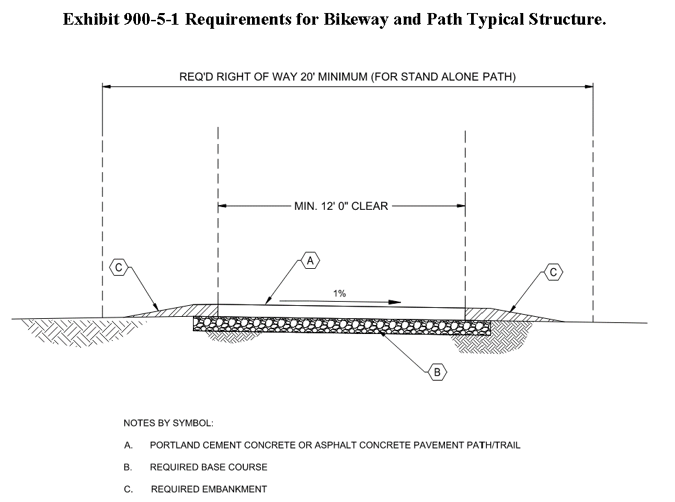
SEC. 900-5 - BIKEWAYS AND TRAILS.
A.
General Planning and Design Requirements. Design of Bikeways and Trails shall meet the requirements of the AASTHO Guide for Development of Bicycle Facilities, Latest Edition.
1.
The minimum paved width for a two-directional bikeway/trail shall be 10 feet. Typical widths range from 10 to 14 feet, with the wider values applicable to areas with high use and/or a wider variety of user groups.
2.
In very rare circumstances, a reduced width of 8 feet may be used where the following conditions prevail:
a.
Bicycle traffic is expected to be low, even on peak days or during peak hours. Pedestrian use of the facility is not expected to be more than occasional.
b.
Horizontal and vertical alignments provide frequent, well-designed passing and resting opportunities.
c.
The path will not be regularly subjected to maintenance vehicle loading conditions that would cause pavement damage.
3.
At a minimum, a 2-foot-wide graded area with a maximum 1V:6H horizontal slope shall be provided for clearance from lateral obstructions such as bushes, large rocks, bridge piers, abutments, and poles. A minimum of 2 feet clearance to post-mounted signs and other traffic controls shall be provided.
4.
A 5-foot separation from the edge of the path pavement to the top of the slope is desirable. If the separation from the edge of the path pavement to the top of the slope is less than 5 feet, physical barriers or rails are recommended in the following situations:
a.
Slopes 1V:3H or steeper, with a drop of 6 feet or greater.
b.
Slopes 1V:3H or steeper, adjacent to a parallel body of water or other substantial obstacle.
c.
Slopes 1V:2H or steeper, with a drop of 4 feet or greater.
d.
Slopes 1V:1H or steeper, with a drop of 1 foot or greater.
5.
The following guidance and the consideration of various factors should guide in the selection of an appropriate design speed:
a.
For most paths in relatively flat areas (grades less than 2 percent), a design speed of 18 mph is generally sufficient, except on inclines where higher speeds can occur.
b.
In areas with hilly terrain and sustained steeper grades (6 percent or greater), the appropriate design speed should be selected based on the anticipated travel speeds of bicyclists going downhill. In all but the most extreme cases, 30 mph is the maximum design speed that should be used.
6.
Cross Slope. Bicycle paths located adjacent to roadway essentially function as sidewalks, and therefore shall comply with the most current regulations for Titles II and III of the Americans with Disabilities Act of 1990 (ADA) and applicable accessibility standards published by the Department of Justice (the 2010 ADA Standards for Accessible Design, "2010 Standards," or later).
a.
One percent cross slopes are recommended on shared use paths, to better accommodate people with disabilities and to provide enough slope to convey surface drainage in most situations.
b.
A cross-slope that provides a center crown with no more than 1 percent in each direction may also be used.
c.
If cross slopes steeper than 2 percent are needed, they shall be sloped to the inside of horizontal curves regardless of drainage conditions.
7.
The maximum grade of a shared use path adjacent to a roadway shall be 5 percent, but the grade should generally match the grade of the adjacent roadway. Grades steeper than 5 percent are undesirable because the ascents are difficult for may path users, and the descents cause some users to exceed the speeds at which they are competent or comfortable.
8.
Where a shared use path runs along a roadway with a grade that exceeds 5 percent, the side path grade may exceed 5 percent but must be less than or equal to the roadway grade.
9.
Grades on shared use paths in independent rights-of-way should be kept to a minimum, especially on long inclines.
10.
Grades on paths in independent rights-of-way should also be limited to 5 percent maximum.
11.
Where a shared use path crosses an unpaved road or driveway, the road or driveway should be paved a minimum of 20 feet on each side of the crossing to reduce the amount of gravel scattered onto or along the path by motor vehicles.
12.
Bridges and Underpasses. railings, fences or barriers on either side of a shared use path on a stand-alone structure should be a minimum of 42 inches high.
B.
Construction Requirements. Bicycle paths may be constructed of Portland cement concrete pavement complying with the requirements of this Section or using Level "A" Minor Asphalt Concrete complying with Sec. 900-3 of this UDC.
1.
Portland cement concrete path pavement shall be of such widths and fixed at such elevations as indicated on the approved plans. Paths shall consist of a one course Portland cement concrete pavement 6 inches in thickness.
2.
The concrete shall have a minimum compressive strength of 3,000 psi at 28 days. The minimum cement content shall be 5.5 bags per cubic yard of concrete. The maximum water content, including free water in the aggregate, shall not be greater than 6 gallons per bag of cement. The consistency of concrete shall be such as to have a slump of from 2 inches to 4 inches.
3.
In preparing the subgrade on which the Portland cement concrete path pavement will be placed, all soft and spongy places shall be removed and all depressions filled with suitable materials which shall be thoroughly compacted in layers not exceeding 6 inches in thickness. The subgrade shall be thoroughly tamped until it is brought to a firm, unyielding surface. It shall have a slope in conformity with the slope of the finished surface of the Portland cement concrete path pavement.
4.
When the Portland cement concrete path pavement is to be constructed over an old path composed of gravel or cinder, the old path shall be entirely loosened, the material spread for the full width of the subgrade and compacted as specified.
SEC. 900-9 - JACKING AND BORING OF PIPE.
A.
Jacking and Boring.
1.
Where crossing existing parish roadways, the applicant shall place water mains, gravity sewer mains and force main pipes by jacking and boring. A casing shall be jacked through the embankment and service provided by a carrier pipe.
2.
The applicant shall provide a casing of welded steel pipe meeting ASTM A53, Grade B, and have a minimum yield strength of 35,000 psi. The exterior of the casing pipe shall be coated with coal tar epoxy or bituminous asphalt. Provide at least the wall thickness shown in the following table:
Exhibit 900-9-1
3.
Where carrier pipe nominal diameter is greater than 48 inches, the applicant shall provide a minimum casing pipe diameter great enough to provide a minimum 3-inch radial clearance between the casing pipe and the "bell" outside diameter of the carrier pipe. The applicant shall provide thickness calculations prepared by a professional engineer licensed in the State of Louisiana and submit those calculations to the Department of Engineering.
4.
For casing pipes larger than 36 inches in diameter, the applicant may choose to furnish casing pipe with 2-inch diameter threaded grout holes or nipples at centerline and crown for pressure grouting. The spacing of grout holes shall not exceed a spacing of 5'. Neat cement grout shall be used for filling voids outside of a casing.
5.
The applicant shall provide casing spacers for all carrier pipes.
a.
Casing spacers shall be sized sufficiently to provide a minimum clearance of 2 inches between outside of carrier pipe bells or couplings and inside of casing. The applicant shall provide spacers consisting of the following components:
i.
Spacer Band Material. Minimum 14-gauge steel band of either Type T-304 stainless steel or Carbon steel coated with fusion bonded epoxy or PVC coating.
ii.
Spacer Liner Material. Ribbed liner of PVC or EPDM rubber designed to overlap the edges of the spacer band and prevent slippage. Provide a liner of a minimum thickness of 0.090 inches and a hardness of 85-90 durometer "A."
iii.
Spacer Width. As recommended by spacer manufacturer for the specific application. Provide spacers with a minimum width of 8 inches. The applicant shall obtain the manufacturer's approval for installations exceeding 300 feet in length, carrier pipes in excess of 48 inches in diameter or multiple carrier pipes in casing. The applicant shall provide risers of minimum 10-gauge steel of the same material and requirements as spacer band. Spacers shall be welded to the spacer band. Risers suitable for supporting the weight of carrier pipe shall be provided. Risers shall be minimum 10-gauge steel risers of same material and requirements as spacer band.
6.
When the grade at the jacking or boring end is below ground surface, the applicant shall excavate suitable pits or trenches for conducting operations and placing joints of pipe. The applicant shall provide shoring to prevent earth caving in accordance with the requirements of with applicable federal, state, and local regulations, laws, and rules; but not be less than the standards and regulations established by OSHA in 29 CFR Part 1926.
7.
The applicant shall not weaken or damage the existing embankment. Dips or settlement in the embankment shall be considered damage and shall be repaired as directed by the Department of Engineering.
8.
The applicant shall use heavy duty jacks specifically designed for forcing pipe through the embankment. The use of excavators to pull or push casing through embankment shall be prohibited. The jacks shall apply even jacking pressure to all jacks and transmit jacking pressure to the pipe end through a jacking head. The applicant shall provide a jacking head designed and constructed so that pressure is uniformly applied around the ring of the pipe. The applicant shall provide a backstop or jacking frame which is adequate to resist pressure of the jacks under load. The applicant shall pipe on guides properly fastened together to support the pipe in the proper direction at correct grade.
9.
A steel cutting edge may be used around the forward end of pipe, constructed so that it will transmit pressures uniformly around the ring of the pipe.
10.
The applicant shall continue jacking without interruption, to prevent pipe from becoming firmly set in the embankment.
11.
The applicant shall not allow pipe to vary horizontally or vertically by more than 1/4 inch in 10 feet from the line and grade shown on the approved plans. Any variation must be regular, and no abrupt changes in direction will be permitted. The applicant shall remove and replace pipe misaligned in jacking operations at his expense.
Sec. 900-2.1 - Generally.
A.
Compliance Required. All lots and blocks created or re-subdivided must meet the minimum lot and block size and dimension standards of this section and the zoning district in which the site is located. If requirements conflict, the more restrictive shall apply.
Sec. 900-2.2 - Block standards.
A.
Adequate Building Sites Required. Provisions of adequate building sites suitable to the special needs of the type of land use (residential, commercial, or other) proposed for development shall comply with the minimum standards established in this UDC.
B.
Block Lengths. No residential block shall be longer than 1,500 feet, unless it abuts Lake Pontchartrain, a waterway, an interstate or major arterial, or some other feature that prohibits street connectivity.
Sec. 900-2.3 - Lot standards.
A.
Remnants Not Allowed. All lots and blocks created or reconstructed must meet the minimum lot and block size and dimension standards of this section and the zoning district in which the site is located. If requirements conflict, the more restrictive shall apply.
B.
Lot and Dimension Requirements. Lots shall comply with the minimum dimensions established in this UDC in accordance with Chapter 400, Zoning, and be calculated exclusive of any public street right-of-way or private drive. Where minimum dimensions are not established in a zoning district, lots shall connect to central water systems and central sewer systems when available and shall comply with the following:
1.
Lots with central sewerage shall have a minimum lot area of 7,500 square feet with a minimum lot frontage of 75 feet and depth of 100 feet.
2.
Lots without central sewerage shall have a minimum lot area of 40,000 square feet and a minimum lot frontage of 150 feet and depth of 120 feet.
3.
All lots or development sites shall be at least 1 acre in area.
Exhibit 900-2-1 Lot Area and Dimension Requirements.
C.
Lot Frontage. All lots shall front on a public street or private street constructed to or improved to parish standards.
D.
Lots Fronting a Cul-de-Sac or Road Having a Curve. Lots fronting a cul-de-sac or a road having a curve shall comply with the requirements for frontage set forth in Exhibit 900-2-2.
Exhibit 900-2-2 Frontage Requirements.
E.
Variation in Front Yard. Except as permitted elsewhere in this UDC, where the average depth of existing front yards on lots improved with buildings located within 100 feet, measured from the outer corners of the front property line of the subject property on both sides of the property and of the street, within the same zoning district, is less than the minimum required front yard, the front yard on the subject property may be the average of the of the existing yards; however, no front yard shall be less than 10 feet. The front yard setbacks of the properties within 100 feet, as measured from the outer corners of the subject property's front property line, shall be provided by the subject property owner or applicant.
F.
Lot Lines.
1.
All lots, so far as practical, shall have side lot lines at right angles to straight street lines or radial to curved street lines. Unusual or odd-shaped lots having boundary lines that intersect at extreme angles shall be avoided.
2.
For interior lots, the lot line common to the street right-of-way line shall be the front line. All lots shall be arranged so that the rear line does not abut the side of an adjacent lot.
G.
Lot Orientation.
1.
General. For interior lots, the lot line common to the street right-of-way line shall be the front line. All lots shall be arranged so that the rear line does not abut the side of an adjacent lot.
2.
Corner lots. The lot frontage shall bear the official municipal address in accordance with provisions for survey and street address in this UDC.
3.
Through lots or double frontage lots. Lots with double frontage (excluding alleyways) should be avoided. Both lot frontages shall be front lines for setback purposes. The 911 Communications District shall determine which frontage must bear the official municipal address, and the address shall be posted on the building elevation that corresponds to the frontage that is assigned the official address, in accordance with provisions for survey and street address in this UDC.
4.
Lot remnants. No lot or parcel shall be created that fails to meet the minimum standards of the applicable zoning district and this UDC, except pursuant to a PUD or Planned Development that provides for the perpetual maintenance of such remnants.
H.
Resident Number and Mailing Address. All lots, in addition to a lot number, will be assigned a resident number which shall become the permanent mailing address. The applicant shall coordinate addresses with the parish 911 addressing office.
I.
Flag Lots.
1.
A flag lot refers to a lot configuration where a standard lot is connected to the public right-of-way by a strip of land that fulfills minimum requirements for access and utilities, as illustrated in Exhibit 900-2-3.
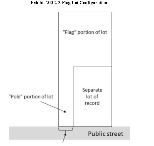
a.
Minimum area, open space, and dimension requirements of the 'flag' portion of the lot. The minimum area, open space, and dimension requirements (including but not limited to minimum lot width, setbacks, front and rear lot line requirements) of the 'flag' or standard lot, not including the area of the access strip or driveway, shall be consistent with the minimum lot size requirements for the zoning district in which the property is located.
b.
Requirements for the 'pole' portion of the flag lot. The minimum lot width on the "pole" portion of the lot is 30 feet. The maximum lot width on the "pole" portion of the lot is 60 feet.
J.
Greenspace Requirements.
1.
All newly created or extended subdivisions or PUDs with more than 25 lots must have land set aside within the development for the use of residents. This land must have a minimum area of 580 square feet per residential lot in the total subdivision and is referred to as "Greenspace."
2.
The Greenspace must be within the subdivision development and must not be separated from the development by any major local roadway or federally maintained roadway.
3.
Greenspace cannot include required Street Landscape Areas or Natural Areas, or be developed as part of a green belt, reserved easement, servitude, or golf course.
4.
Greenspace located along existing roads must be a minimum of one-quarter acre in area and at least 100 feet in width along the roadway.
5.
Greenspace located along any property boundary not fronting on a road must be a minimum of one quarter acre in area and at least 50 feet in width along the roadway.
6.
At least one quarter of all required Greenspace must be dedicated to supporting residents' active recreation. Exhibit 900-2-4 provides appropriate recreational amenities based on the total number of lots or units proposed within a subdivision. Exhibit 900-2-4 is not an exhaustive list of appropriate recreational amenities. Similar scaled amenities or waivers not listed in Exhibit 900-2-4 may be approved for subdivisions with more than 25 lots subject to the Department of Planning and Development's review and the Planning and Zoning Commission's approval.
Exhibit 900-2-4 Active Recreation Amenities Permitted in Greenspace.
K.
Planting Requirements.
1.
All newly created or extended subdivisions or PUDs with more than 25 lots must provide planted Class A tree(s) in the front yard of each lot at least 30 ft. apart prior to the property owner obtaining occupancy of the structure per Exhibit 900-2-5 Required Trees in Major Subdivisions. As defined, a Class A tree, at the time of planting, shall have a minimum caliper of at least 2.5 inches, measured 6 inches above the root ball and a minimum height of 10 feet, as per the National Nursery Association Standards. A list of appropriate Class A trees can be found in Exhibit 600-3-19 Approved Native Trees and Shrubs. All required trees shall be watered, mulched, and maintained at all times and shall be located outside of any required easement or servitude. Any trees which are diseased or dying as certified by a registered landscape architect or arborist may be removed and replaced at the cost and expense of the owner.
Exhibit 900-2-5 Required Trees in Major Subdivisions.
Sec. 900-3.1 - Traffic impact analysis.
A.
Purpose and Intent. The purpose and intent of this section is to protect the health, safety and welfare of the citizens and visitors of St. Tammany Parish by ensuring the provision of safe and adequate roadway facilities. The provisions of this article establish requirements for transportation studies that provide information on traffic projected to be generated by proposed developments. It is the further intent of this article to establish requirements for the identification of any potential traffic operational problems or concerns, and to establish requirements for the identification of mitigation measures and requirements for the implementation of those mitigation measures.
1.
Developments seeking access to state roadways where a review of a traffic impact study is performed by Louisiana Department of Transportation and Development (LADOTD) are not exempt from the requirements in this policy.
2.
Applicants seeking direct access to a state highway, or local road with an access point within 0.25 mile of a state highway, shall comply with the requirements of this section and the requirements of Louisiana Administrative Code Title 70, Chapter 11 - Traffic Impact Policy for New Access Requests Affecting State Highways.
B.
When Required. A transportation impact analysis (TIA) shall be required for all changes of use, subdivisions or developments when the following projected peak hour trip threshold levels are met or exceeded. In the event that alternative threshold levels are specified, the more restrictive shall prevail.
1.
The parish has the right in the administrative review process to exempt a development from the required TIA if any of the following conditions are satisfied, unless required by the subdivision procedures.
a.
For developments with access connection to only right-of-way controlled by the State of Louisiana Department of Transportation and Development (LADOTD) and an access permit has been approved by LADOTD. Applicant shall be responsible for requesting the waiver from the Department of Engineering through written request and for providing a copy of the approved LADOTD access permit.
b.
If the change in use or expansion of an existing development has a trip generation less than or equal to the existing use. Applicant shall be responsible for requesting the waiver from the Department of Engineering through written request and for providing documentation demonstrating current and proposed trips generated from development.
c.
Developments where use of property generates less than 50 peak hour trips. Applicant shall be responsible for requesting the waiver from the Department of Engineering through written request and for providing documentation demonstrating current and proposed trips generated from development.
Exhibit 900-3-1 Traffic Impact Analysis Thresholds.
2.
The peak hour trips shall not be the only factor in the determination of the analysis that will be required. Though not generally required, at the discretion of the Department of Engineering or the Planning and Zoning Commission, other items which significantly influence the traffic movements or safety may require a higher level of study. These include but are not limited to the following:
a.
Areas with a high amount of traffic accidents.
b.
Areas with inadequate sight distance.
c.
Areas where there are currently high traffic volumes on surrounding roads that may affect movement to and from the proposed development.
d.
The development will be located in an area that is currently undergoing substantial growth.
e.
The development will be located in an area that is currently experiencing extreme problems with traffic congestion.
3.
Expansion of an existing project shall also be subject to the requirements of this section. When determining whether the project meets the threshold, trips from the existing land use shall be included in the trips that are considered "produced" by the project. If the sum of previous and projected trips is more than the threshold identified in Exhibit 900-3-1 above then the Department of Engineering shall require the applicant to prepare a TIA.
4.
Based on the results of the administrative review of the proposed project the Department of Engineering has the authority to require traffic mitigation measures, even if a formal TIA is not required.
5.
The applicant shall meet all applicable requirements found in this UDC. Additionally, the Department of Engineering shall have the authority to require additional improvements or ingress/egress points above the current parish standards if the Director determines based on the TIA or the administrative review that such measures are necessary for health and safety.
C.
Procedures.
1.
The applicant shall submit as a part of the application the number of trips to be generated by the proposed development, calculated as per the requirements of this section.
2.
If a TIA is required for a project pursuant to the provisions of this UDC the Applicant shall employ a licensed professional engineer registered in the State of Louisiana with experience in traffic engineering submitted by the Applicant to prepare, sign, and seal the TIA in conformance with these regulations.
3.
The Applicant shall be solely responsible to bear all costs of employing said engineer and payment of all fees per the parish fee schedule.
4.
The TIA shall be submitted along with the Concept Plan application. In the event that a TIA is required but a Concept Plan application is not required, the TIA shall be submitted along with the building permit application.
5.
In no instance shall a building permit be issued for a development that is subject to the TIA requirements of this article prior to the submission and approval of the TIA.
D.
Fees. A review fee will be assessed on every applicant that is required to submit a TIA for this service. This fee shall consist of a $500.00 submittal fee.
E.
Building Permit. When applicable, a building permit or work order will not be issued until:
1.
An approved TIA considering all proposed development shows little or no impact on existing traffic conditions.
2.
A mitigation proposal developed based upon an approved TIA has been accepted by the Department of Engineering and the Planning and Zoning Commission.
F.
Mitigation, General.
1.
When applicable, A certificate of occupancy will not be issued until all mitigation measures identified in the approved TIA have been constructed and accepted by the Department of Engineering and the Planning and Zoning Commission.
2.
Mitigation shall also be in coordination with the most recent 2040 Comprehensive Plan to benefit the area affected, as well as the parish's 5-year infrastructure plan.
3.
Prior to approval, the applicant shall verify with the Department of Engineering whether the 2040 Comprehensive Plan or ten-year infrastructure plan proposed route or improvement will affect the subject property. If so, the applicant must consult with the Department of Engineering to coordinate planning for sufficient access. The most recent map outlining the 2040 Comprehensive Plan and the 5-year infrastructure plan can be obtained from the Department of Engineering.
4.
When applicable, construction of mitigation shall not begin until the TIA and mitigation proposals contained within have been accepted by the Department of Engineering and the Planning and Zoning Commission.
G.
Documentation. The TIA report shall be prepared documenting the study, the data used, the findings, and the recommendations of the study. The TIA will be reviewed by both the Department of Engineering and the Planning and Zoning Commission. If either the Department of Engineering or the Planning Commission determines that the TIA is inadequate or not in accordance with this section, the applicant shall be required to supplement or modify the TIA to address any deficiencies.
H.
TIA Contents and Format.
1.
The contents of a TIA, as well as the TIA study area radius shall vary depending on the site and prevailing conditions. Content requirements, including the study area radius, shall be established by the applicant and approved by the Department of Engineering prior to the submission of the TIA. The applicants licensed professional engineer registered in the State of Louisiana, prior to initiation of the study, shall determine the study area radius for the TIA. Such radius shall be subject to the approval of the Department of Engineering. Such requirements shall address site, project, and corridor level traffic and transportation issues. Each TIA submitted must take into account all other proposed developments in the study area (all developments for which a Concept Plan application or a PUD application has been submitted). This information shall be obtained from the Department of Engineering.
2.
TIAs shall include the following information:
a.
Threshold 1. When the proposed development results in less than 100 peak hour trips, either AM or PM (whichever is greater) the applicant shall include in the TIA:
i.
Proposed trip generation and distribution with source of information; and
ii.
Sight distance evaluation at proposed driveway locations.
b.
Threshold 2: When the proposed development results in greater than 100 and less than 400 peak hour trips, either AM or PM (whichever is greater) the applicant shall submit:
i.
Proposed trip generation and distribution with source of information;
ii.
Sight distance evaluation at proposed driveway locations:
iii.
Capacity analysis for existing and proposed conditions at intersections within the study area;
iv.
Capacity analysis for proposed conditions at the development driveways;
v.
Left turn lane, right turn lane and signal warrants at the development driveways; and
vi.
Recommendations for mitigating improvements to maintain or improve the existing Level-of-Service, as well as recommendations for driveway locations and configurations.
c.
Threshold 3: When the proposed development results in greater than 400 peak hour trips, either AM or PM the applicant shall submit:
i.
Proposed trip generation and distribution with source of information;
ii.
Sight distance evaluation at proposed driveway locations;
iii.
Capacity analysis for existing and proposed conditions at intersections within the study area established during the Traffic Scoping Meeting;
iv.
Capacity analysis for proposed conditions at the development driveways;
v.
Left turn lane, right turn lane and signal warrants at the development driveways;
vi.
Recommendations for mitigating improvements to maintain or improve the existing Level-of- Service, as well as recommendations for driveway locations and configurations.
vii.
Summary of the crash history within the study area; and
viii.
Review of crash reports and provide recommendations to improve safety. lots and blocks created or reconstructed must meet the minimum lot and block size and dimension standards of this section and the zoning district in which the site is located. If requirements conflict, the more restrictive shall apply.
3.
Each TIA study shall be prepared in the following format:
a.
Description of TIA study area. The description shall specify the boundary of study area and count and analysis sites. A site location map shall be provided. The map shall include roadways that allow access to the site and are included in the study area.
b.
Description of the project. This description shall include the size of the parcel, general terrain features, access to the site, anticipated completion date, and the existing and proposed uses of the site (including phasing). In addition, the square footage of each use or number and size of units proposed shall be specified. A figure (Site Plan) that shows the site development as proposed shall also be included in the report.
c.
Existing conditions. The existing conditions in the vicinity of the project shall be discussed, including a description of the area to be affected by the development. A field inventory of the site and study area shall be conducted. Existing traffic volumes, traffic controls, and geometrics (number of lanes, intersection configurations, etc.) shall be described in detail. This data shall be depicted graphically.
d.
Existing traffic volumes within TIA study area. Average daily traffic counts shall be current (less than one year old from the T.I.A. submittal date). The applicant shall contact the Department of Engineering to obtain current available counts. If current data is not available, the applicant will be required to perform the counts. Peak hour counts shall be conducted at study area intersections during peak hours as determined by the existing roadway counts and approved by the Department of Engineering. These counts shall show all turning movements. The counts shall be conducted during the school year (September through May) and during weeks that have no major school holidays. (These holidays shall include, but not be exclusive to, Thanksgiving, Christmas Break, Spring Break, Mardi Gras, Labor Day, and exam weeks.) The Department of Engineering may be contacted for approval of the planned count dates.
e.
Trip generation estimates and design hour traffic volumes. The calculation of traffic volumes used to determine impacts of the development shall be based on the maximum land use intensity allowed under the existing (or proposed) zoning ordinance.
f.
Trip distribution and traffic assignments. Traffic generated by the site must be distributed and assigned to the roadway network in order to determine the project's impact. The direction a vehicle will take to access or leave the project site is known as trip distribution. Traffic assignment refers to the actual routes taken by project traffic to and from the site. The methodology and assumptions which are used in the determination of trip distribution and traffic assignments shall be described. In the case of projects with several phases to take place over several years, the trip distribution and traffic assignment shall be estimated for the completion of each phase.
g.
Projected traffic volumes within the TIA study area. Project generated and distributed traffic shall be estimated for all intersections in the study area, including any proposed site access driveways and must include a section outlining where turn lane warrants are required. The projected counts will represent the same peak hours that were used for the existing traffic volume counts and will show all turning movements. The trip generations from all other proposed developments in the study area shall also be taken into account. This information shall be obtained by the Department of Engineering. The growth rate percentage to be used for the study area shall also be established by the Department of Engineering.
h.
Capacity analysis. Capacity analyses provide an indication of how well the study area intersections serve existing and future traffic demands. A description of the methodology and level of service (LOS) definitions shall be included within the TIA. For existing, background and future conditions, LOS at all study intersections, inclusive of the project driveway, shall be calculated for signalized and unsignalized intersections. The other proposed developments in the study area shall also be taken into account. An overall LOS "D" shall be considered acceptable for signalized intersections within the parish. For unsignalized intersections, the LOS for the critical movement shall be at LOS "D" or above. In the case where the existing level of service (LOS) is below "D," the mitigation efforts shall improve the LOS to "D" or above.
i.
Volume to capacity (V/C) and average stopped delay must also be presented for both signalized and unsignalized intersections (including 95% queuing length and unserviced demands). To assess quality of flow, roadway capacity analyses are required under the following conditions: existing, no build (per project phase), build (per project phase), and future(total build out).
j.
Traffic Accidents. Three years of the most current accident data shall be obtained for intersections within the study area. This data shall be depicted in tabular form along with a brief description at each critical location. The applicant may contact the Department of Engineering to obtain contact information for the purpose of collecting this data.
k.
Traffic improvements. Unsignalized intersections experiencing significant deficiencies (delays) shall be evaluated for potential signalization or roundabout improvements. Results of these analyses shall be discussed, and recommendations presented. Any planned mitigation, inclusive of roadway improvements, to be completed within the study area shall be identified and discussed.
l.
Conclusions. This section of the traffic study shall summarize the required improvements and the proposed mitigation measures. This shall include, but not limited to:
i.
Existing and future LOS results;
ii.
Proposed mitigation inclusive of all proposed roadway improvements; and
iii.
Resultant LOS with proposed mitigation in place.
m.
Summary, Findings and Recommendations. Mitigation measures shall be discussed in this section. This includes identifying the improvement measures necessary to minimize the impact of the project/development on the transportation system. The study area intersections shall be mitigated at a minimum to operate better than or equal to the "No Build" case, based on the calculated V/C and average stopped delay. In the case where the existing level of service (LOS) is below "D," the mitigation efforts shall improve the LOS to "D" or above.
I.
Trip Generation Rates. To determine whether the requirements of this section are applicable to the proposed project and for the purpose of preparing required transportation impact analyses, applicants shall use the trip rates and methodology contained in the most recent edition of the Institute of Transportation Engineers' (ITE) trip generation manual.
J.
Actions Based on the TIA.
1.
A proposed development which is subject to the TIA requirements of this section shall be disapproved when the results of the required TIA demonstrate that the proposed project will overburden the roadway system or cause a reduction in service of affected roadways below the adopted level of service (LOS) "D." In the case where the existing level of service (LOS) is below "D," the mitigation efforts shall improve the LOS to "D" or above. An applicant, in coordination with the Department of Engineering, may modify the development proposal to minimize the identified traffic-related impacts. Mitigation may include, but shall not be limited to:
a.
Dedication of additional right-of-way;
b.
Rerouting of traffic and proposed access points serving the proposed project;
c.
Participation in funding transportation facilities, including signals and intersection improvements;
d.
Traffic signal timing and/or phasing adjustments (with coordination and approval from the owner of the signal);
e.
Restriping or reconfiguration of intersections;
f.
Adding additional intersection through or turn lanes;
g.
Installation of a signal, installation of a roundabout; or
h.
Any other recommendations by the Department of Engineering upon review and analysis of the TIA.
2.
Applicants will assume the full and sole responsibility for the cost and implementation of all identified improvements which mitigate the traffic impact of their proposed development, unless funding can be provided through any grant mechanism.
3.
If a traffic mitigation is part of an approved transportation impact study, all approved traffic improvements must be implemented prior to receipt of an occupancy Certificate or As Built Plan approval, whichever is appropriate, unless otherwise provided for as part of the approved TIA and coordinated with the parish.
Sec. 900-3.2 - General planning and layout requirements for streets.
A.
Arrangement. The arrangement of streets shall be structured to enable:
1.
The continuation of the existing streets in adjoining areas.
2.
All street intersections and street widths shall be safe for traffic.
3.
Offset streets shall be avoided. Minimum offsets shall be at least 125 feet between the center lines of two opposing offset streets.
4.
All lots within new subdivisions must have either a public or private street or road frontage constructed for the full lot frontage in accordance with the provisions as established within this section.
5.
Any newly constructed drive, road or street located in a Critical Drainage Area shall be constructed at in a manner that enables safe use of streets under a 50-year flood design standard. Exemptions may be granted by the Department of Engineering in coastal zoned areas when supported by engineering studies that constructing the road to BFE would cause adverse impacts to adjacent land.
6.
Subdivision entrance and exit ways.
a.
Purpose and minimum standard. To ensure safe and efficient traffic flow, subdivisions with more than 100 lots shall have at least 2 ingress and 2 egress points providing vehicular access to an existing public street.
b.
Limited exceptions. Exceptions to this standard may be provided by the Planning and Zoning Commission upon determination that an additional entrance may pose a significant safety hazard or if the Louisiana Department of Transportation and Development determines otherwise in writing.
c.
Minimum design standards.
i.
The entrance and exit points must be designed with a median at least 6 feet wide, 100 feet deep, and having a minimum 3-foot radius on each end.
ii.
The median shall be constructed of a 5-inch high, 8-inch-wide curb compatible with adjacent public street material and planted with seed, sod, or other living landscape materials.
7.
Multi-Family entrance and exit ways.
a.
Purpose and minimum standard. To ensure safe and efficient traffic flow, multi-family developments with more than 100 units shall have at least one ingress and egress point, and one additional one-way drive providing vehicular access to an existing public street.
b.
Limited exceptions. Exceptions to this standard may be provided by the Board of Adjustments upon determination that an additional entrance may pose a significant safety hazard or it the Louisiana Department of Transportation and Development determines otherwise in writing.
B.
Limited Access Roads. In special cases, where in the opinion of the Planning Commission, the requirements of safety demand, especially where subdivisions front on heavily traveled thoroughfares; such thoroughfares may be designated as limited access roads. In such cases, local traffic streets shall be required adjoining and paralleling the thoroughfares with access thereto at specified intervals only. In no case will lots be positioned with direct access onto a limited access roadway or State Highway without the permission of the Louisiana Department of Transportation and Development.
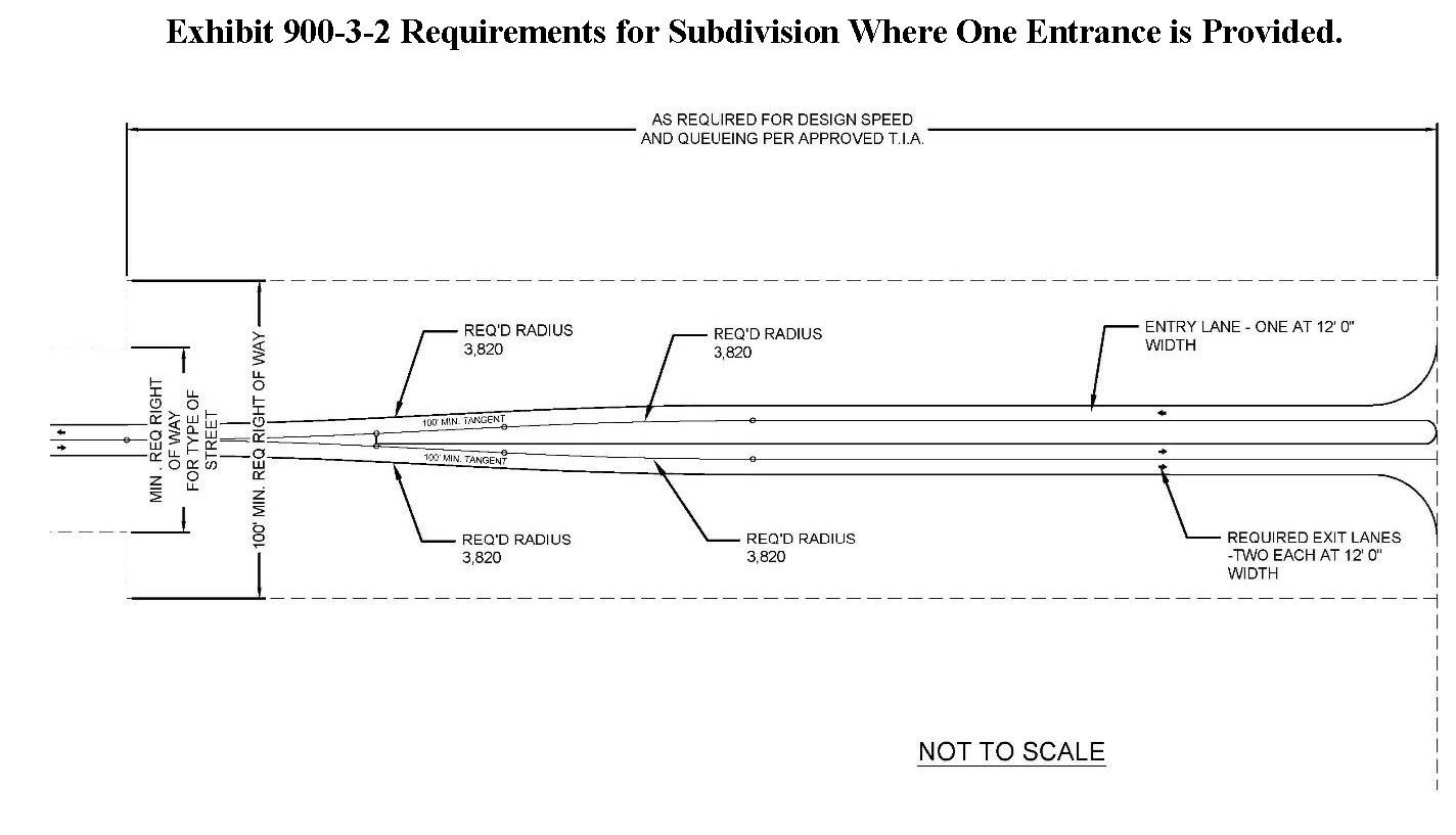
C.
Subdivision Entrances. In the interest of public health and safety, to provide for efficient traffic flow at subdivision entrances, and to promote aesthetic qualities, all proposed subdivisions where only one entrance is provided shall be required to build the entrance to the following minimum standards:
1.
Right-of-way width. An 80' wide right-of-way shall be reserved at the entrance of subdivisions.
2.
Median Required for Entrance. For all single access subdivisions the applicant shall design and construct a median at the entrance to segregate traffic flow. The applicant shall provide one 12-foot-wide ingress travel lane on the entrance side of the median and a minimum of two 12-foot-wide each egress travel lanes on the exit side of the median. This entrance shall contain directional arrows and be striped accordingly with materials as approved by The Department of Public Works and as provided for within this UDC. The transition from this boulevard section to other roadway section shall be constructed in accordance with the requirements set forth in Exhibit 900-3-2.
3.
Minimum Median Width. The minimum width of the median shall be 6 feet wide with a minimum radius at both ends of 3 feet.
4.
Median Design. The median shall be of a curb and crowned design with a turf or vegetative cover or other similar material.
5.
Curbing. The curbing shall have a minimum height of 6 inches and minimum width of 7 inches at the bottom of the curb face and a minimum width of 6 inches at the top of the curb face.
6.
Curb material. Curbing shall be constructed of Portland cement concrete.
7.
Groundcover. The turf or vegetative cover shall be made up of grass and/or any other combination of living landscape materials such as trees, bushes, shrubs and flower beds.
8.
Maintenance. Maintenance of the median shall be the responsibility of the applicant and/or homeowners association following acceptance of the work by the Department of Engineering and Planning and Zoning Commission.
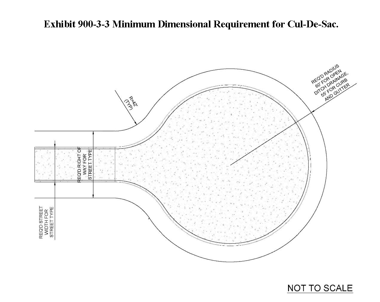
9.
Dead End Streets. Dead end streets are prohibited, however, cul-de-sacs or other approved turnarounds may be constructed, provided that the following minimum standards are met.
a.
Radius. The radius of a cul-de-sac shall be 60 feet when the design employs open swale ditches and 55 feet when subsurface drainage is used. The inside turning radius shall be a minimum of 46 feet.
b.
Length. A street terminated by a cul-de-sac shall be no longer than 700 feet in length.
c.
Signage. The entrance to a street terminated by an approved turnaround shall be posted with a sign stating "No Outlet."
d.
Waiver. The Planning Commission has the authority to waive the minimum design standards for streets terminated by a turnaround only when it is deemed reasonable and compatible with topography, aesthetics, planning, development, or need.
e.
Landscape Islands. Curbed or uncurbed landscape islands shall not be permitted within any cul-de-sac.
D.
Minimum Widths of the Right-of-Way.
1.
Minimum width. The minimum width of right-of-way of public or private streets in any subdivision shall be 60 feet, except where subsurface drainage is provided. Streets having these features may be reduced to 50 feet in width.
2.
Boulevards or Avenues. Boulevards or avenues in any subdivision shall have a minimum right - of way not less than 80 feet wide.
3.
Connection to Existing Streets. Streets that are obviously in alignment with others already existing shall bear the names of the existing streets.
4.
Street Names. Duplication of street names must be avoided. In no case shall there be a duplication of a street or road name within a fire protection district or of new street names within any of the municipalities of the parish.
5.
Street Sign. A uniform street sign system marking each street intersection must be installed by the applicant prior to obtaining As Built Plan approval, in accordance with the specifications referenced to within this article.
6.
Traffic Control Signs. Traffic-control signs will be installed by the applicant, prior to obtaining As Built Plan approval and be in conformance with the requirements of this code. The applicant shall be responsible for the maintenance of all streets, drainage ditches and associated infrastructure until all improvements have been completed and until the associated Warranty Obligation is released.
(Ord. No. 25-5700, § Exh. A, 3-6-2025)
Sec. 900-3.3 - Street design requirements.
A.
Purpose. The purpose of this section is to provide roadway design and construction standards to serve as a guide for acceptance of new roadways that will be private or dedicated to the public and placed into the parish roadway system for maintenance. It also provides guidelines for acceptance of existing private roadways into the roadway system.
B.
Functional Classification. Unless otherwise provided for within this code, the functional classification for existing roadways shall be determined by the Department of Engineering. The Department of Engineering shall utilize the latest version of the Statewide Highway Functional Classification Maps prepared by the Louisiana Department of Transportation and Development, Office of Multimodal Planning in cooperation with the U.S. Department of Transportation Federal Highway Administration.
C.
Geometric Design.
1.
For Existing or Proposed Roadways with an AADT of 400 or Less. All horizontal and vertical geometry for local streets with an AADT of 400 or less shall meet the American Association of State Highway and Transportation Officials (AASHTO) "Guidelines for Geometric Design of Very Low Volume Local Roads (ADT less than or equal to 400).
2.
For Existing or Proposed Roadways with AADT greater than 400. All horizontal and vertical geometry for local streets shall meet the American Association of State Highway and Transportation Officials (AASHTO) "A Policy on Geometric Design of Highways and Streets" latest edition, as modified by the Louisiana Department of Transportation and Development Road Design Manual.
3.
Design Speed. The applicant shall utilize design criteria for a minimum design speed of 25 miles per hour. Horizontal and vertical geometry for collector streets shall meet the AASHTO "A Policy on Geometric Design of Highways and Streets" latest edition, criteria for a design speed within the range of 30 mph to 45 mph as determined by the Department of Engineering.
4.
Minimum Requirements Horizontal Curves. In no case shall a horizontal curve have a radius less than 200 feet. Tangent distance between reverse curves shall be 100 feet minimum. Horizontal curves shall be designed to provide for proper stopping sight and passing sight distance for the design speed of the roadway. Horizontal curves shall be circular curves. Compound and spiral curves shall be prohibited.
5.
Superelevation. Superelevation is permitted for roadway design. Superelevation shall be limited to 4% for all roadways.
6.
Longitudinal Profile.
a.
General. Vertical curves shall be required when the algebraic difference in the change of grades is greater than 1%. Vertical curve shall be designed to meet the design values listed in American Association of State Highway and Transportation Officials (AASHTO) "A Policy on Geometric Design of Highways and Streets," latest edition, criteria for the design speed of the roadway.
i.
Curbed Roadways (Curb and gutter bottom). Roadways with curb and gutter drainage shall have a minimum longitudinal grade of 0.35%.
ii.
Uncurbed Roadways. Roadways with open ditch drainage shall not be required to maintain a minimum longitudinal slope. Ditch grades for all roadside ditches shall be greater than 0.1% in all cases.
iii.
Inlets. Inlets shall be spaced as required to meet drainage design criteria specified within this code.
b.
Cross Slope. Except where superelevation is required, the minimum cross slope shall be 1.5% towards the edge of the roadway and shall not exceed 2.5% from the edge of the roadway. Designs which provide drainage by providing a downhill slope from the edge of the roadway to the centerline to provide drainage shall be prohibited.
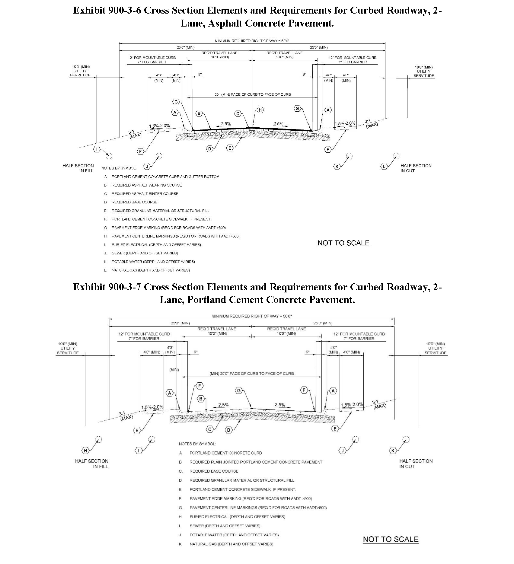
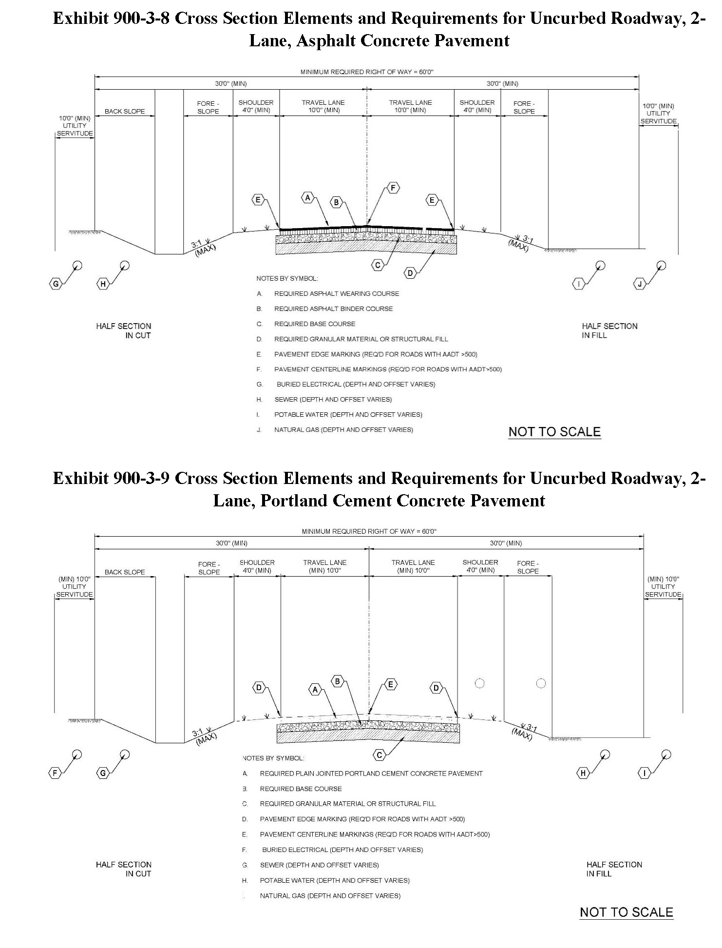
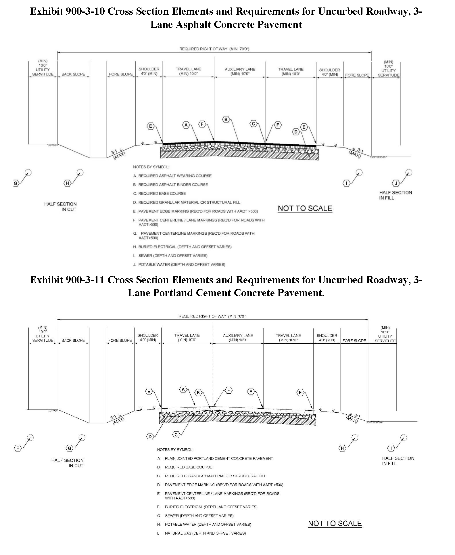
c.
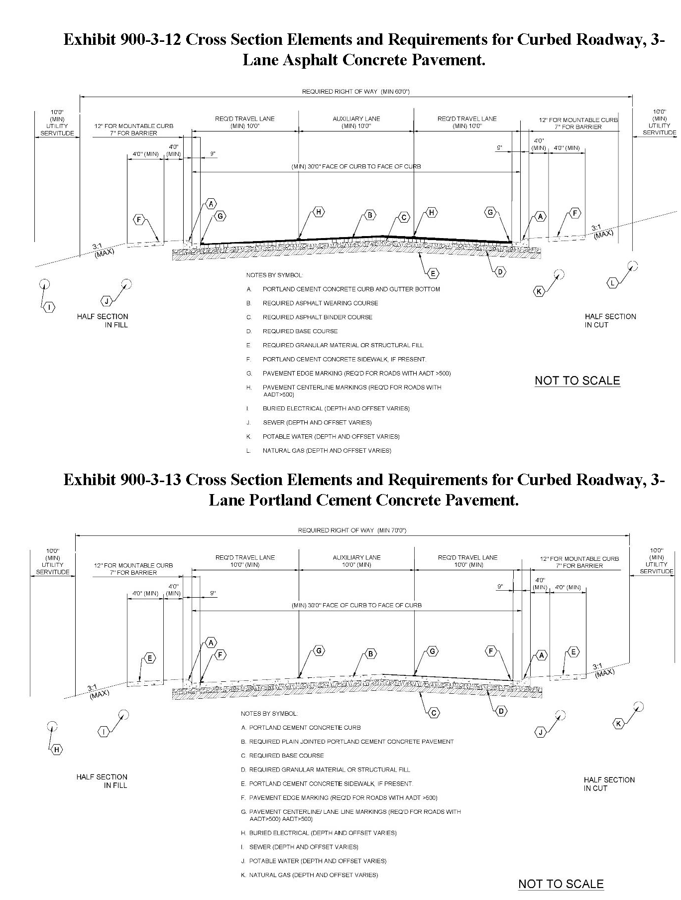
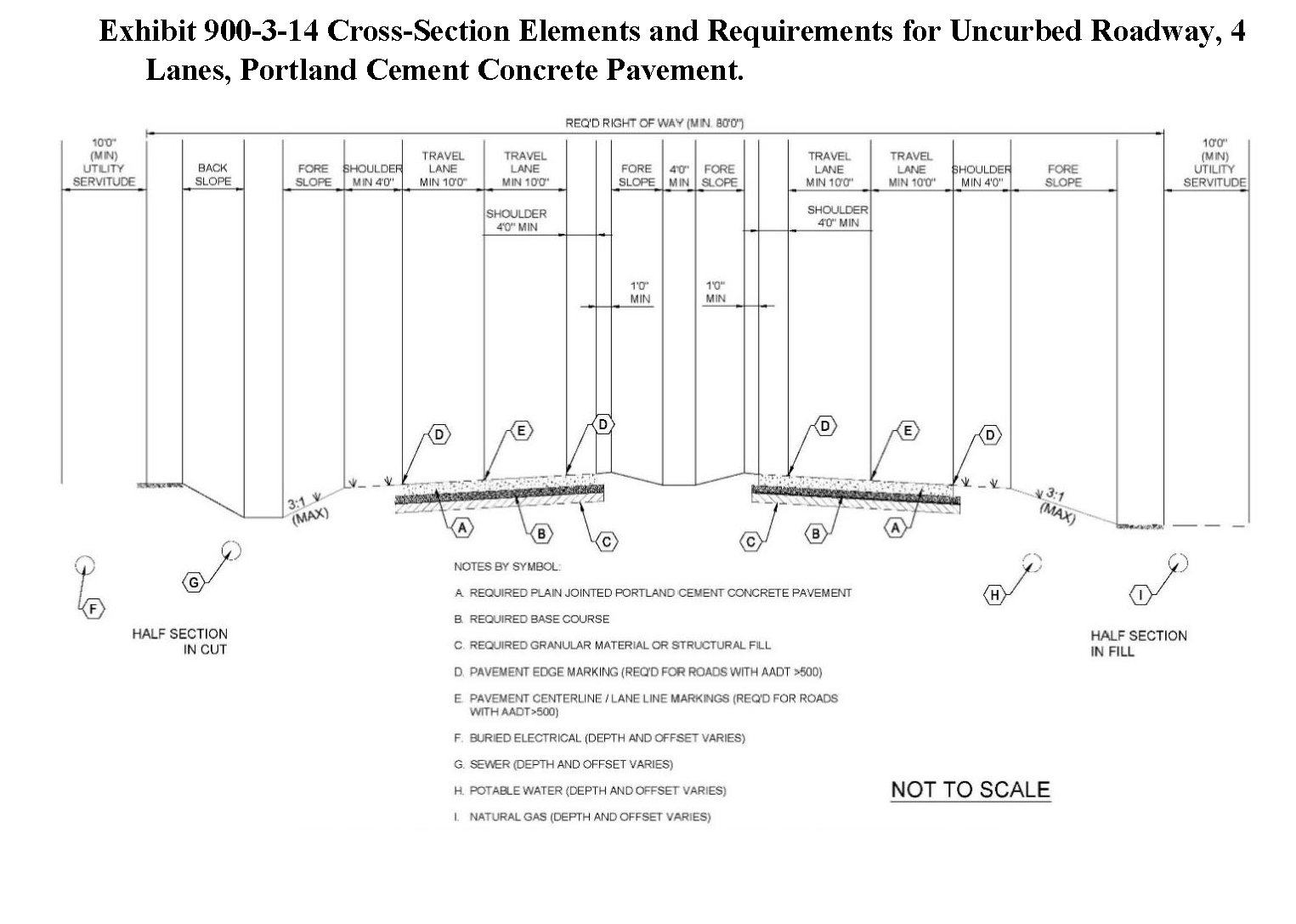
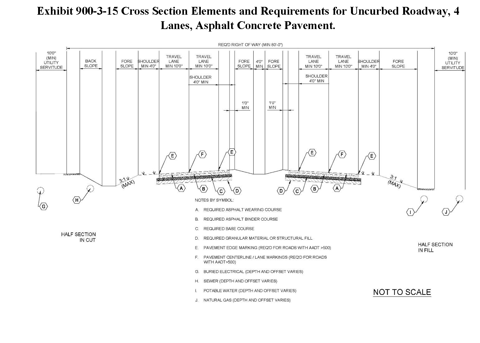
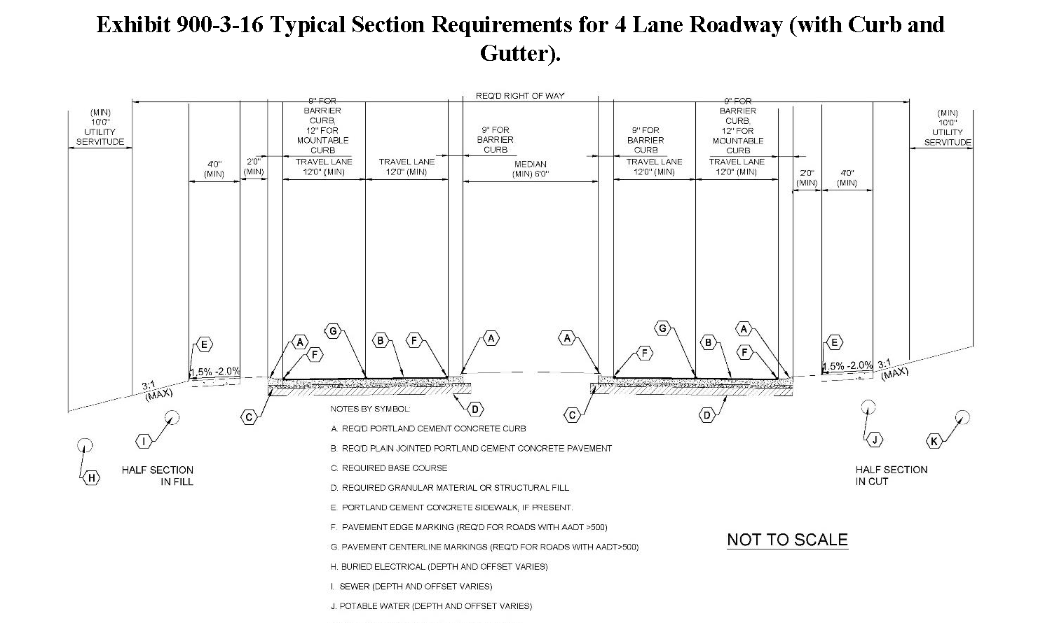
Cross section elements and requirements.
i.
The minimum width of all through travel lanes and auxiliary lanes shall be 10 feet with 4-foot vegetated shoulders.
ii.
The minimum width of all auxiliary lanes (such as turn lanes) shall be 11 feet.
iii.
Embankment foreslope and backslope shall not be steeper than 3H:1V.
iv.
A minimum of 4 ft. width shoulder on both sides of the road is required and must be shown on the cross section of all roadways and reflected in the plat.
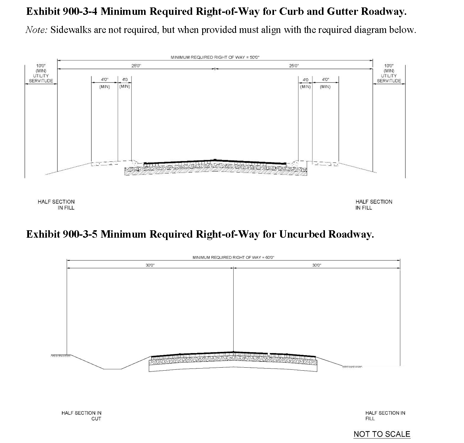
d.
Minimum width requirements. The following figures illustrate minimum width requirements and embankment design requirements for various roadway types:
D.
Pavement Design, General.
1.
Methodology. Applicants shall design pavement sections utilizing the general methodology prescribed within this section. Applicants may provide Portland cement concrete (rigid) or asphaltic concrete (flexible) pavements designed and constructed in accordance with the requirements of this code.
2.
Design Period. The design period is the time from the original construction to a terminal condition for a pavement. The design period for all roadways shall be 20 years.
3.
Traffic Forecasting for Pavement Design. The applicant shall provide an estimate of the traffic volume for the design life of the proposed roadway prepared by a professional engineer registered in the State of Louisiana. The traffic forecast shall include:
a.
Estimated Two Way Traffic (Average Daily Traffic)
b.
Estimated Percent of Trucks in Design Direction.
c.
Number of Lanes in Design Direction.
d.
Percent of All Trucks in Design Lane.
e.
Percent Trucks in Design Direction.
f.
Estimate of Percent of ADT for FHWA Vehicle Classes 1 through 13, inclusive.
g.
Estimated Annual percent Growth.
h.
Estimated Annual percent Growth for Trucks.
i.
Accumulated 18-kip ESALs for Performance Period for FHWA Vehicle Classes 1 through 13, inclusive.
4.
Accumulated 18-kip ESALS for Performance Period for each FHWA Vehicle Class shall be calculated from the following equation:
![]()
5.
The total ESAL for the Performance Period shall be calculated from the following equation:

6.
Minimum ESAL Loadings for Various Roadways and Pavements. Pavement sections shall be designed for the accumulated ESALS calculated in the traffic forecast or the number of ESAL's contained below, whichever is greater.
Exhibit 900-3-17 Minimum ESAL Loadings for Various Roadways.
7.
Design Values. The following design values are to be utilized for the determination of required ESALs for pavement design:
Exhibit 900-3-18 ESAL Design Values (ACP).
Exhibit 900-3-19 ESAL Design Values (PCCP).
E.
Pavement Design, Flexible Pavement (Asphalt Concrete Pavement (ACP)).
1.
When providing flexible pavement, applicant shall design the pavement using the traffic forecast for pavement design and design the pavement utilizing the flexible pavement methodology contained within the Louisiana Department of Transportation and Development Pavement Design Guide (13), Chapter 6, Flexible Pavement Design.
2.
Methodology. The applicant shall provide a pavement design with a design structural number which exceeds the required structural number as determined utilizing the equation below. Inputs required are depicted within the Table below:

Exhibit 900-3-20 Flexible Pavement Design Values.
3.
Calculation of Structural Number of Proposed Pavement Section. Design Structural Number of the proposed pavement section shall be calculated utilizing the following equation:
![]()
4.
Acceptable Design Values. Design values to be utilized for layer coefficients for design of Flexible Pavement are as follows:
Exhibit 900-3-21 Flexible Pavement Acceptable Design Values.
5.
Minimum Typical Section. The minimum typical section for any asphaltic concrete street or roadway shall consist of 4 inches of Superpave asphaltic concrete with 12 inches of base course or 10 inches of soil cement with appropriate treatment to prevent cracking placed over 12 inches of AASTHO A-4 (or better) fill placed over a proof rolled subgrade, all furnished, placed, compacted, and finished in accordance with the requirements of this code.
6.
Asphalt Mixture Requirements. Asphalt mixtures shall be a Superpave asphaltic concrete mixture which shall be produced, transported, and placed in accordance with the requirements of the Louisiana Standard Specifications for Roads and Bridges and the Louisiana Department of Transportation and Development "Application of Quality Assurance Specifications for Asphalt Concrete Mixtures," and the requirements for street construction contained within this UDC.
F.
Pavement Design, Rigid Pavement (Portland Cement Concrete Pavement (ACP)).
1.
When providing rigid pavement, applicant shall design the pavement using the traffic forecast for pavement design and design the pavement utilizing the flexible pavement methodology contained within the Louisiana Department of Transportation and Development Pavement Design Guide (13), Chapter 7, Rigid Pavement Design.
2.
Methodology. The applicant shall provide a pavement design with a design thickness which exceeds the required thickness as determined utilizing the equation below. Inputs required are depicted within the Table below:
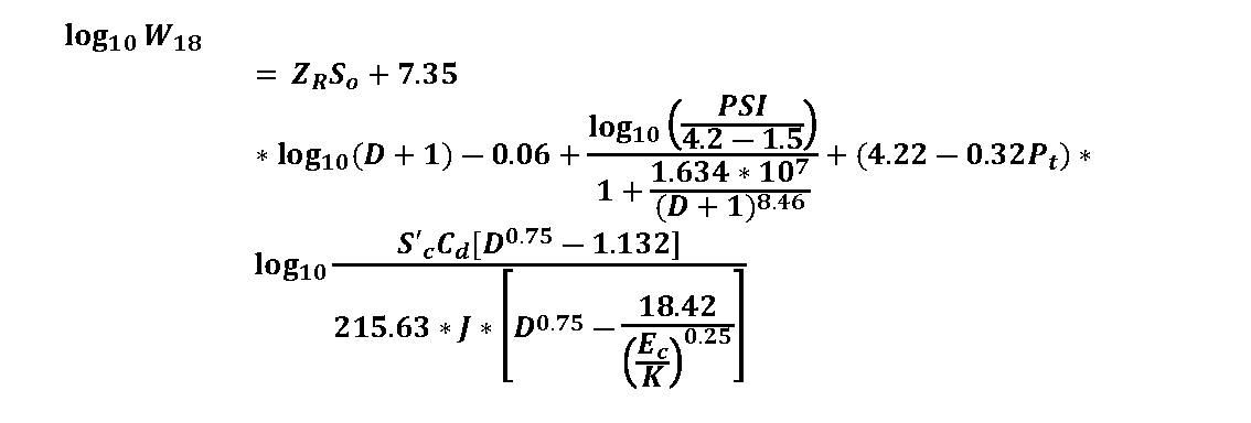
Exhibit 900-3-22 Rigid Pavement Acceptable Design Values.
3.
Minimum Typical Section. The minimum typical section for any Portland cement concrete pavement street or roadway shall be 6 inches of Portland cement concrete with 12 inches of AASHTO A-3 or better base material or 10 inches of soil cement over a proof rolled subgrade, all furnished, placed, compacted, and finished in accordance with the requirements of this code.
4.
Portland Cement Concrete Pavement Mixture Requirements. Portland cement concrete mixtures shall be a Type B, D, or E Portland cement concrete mixture which shall be produced, transported, and placed, finished, and cured in accordance with the requirements of the Louisiana Department of Transportation and Development "Application of Quality Assurance Specifications for Portland Cement Concrete Pavement and Structures" and the requirements of this code.
5.
Jointing Requirements.
a.
Expansion Joints. At a minimum, concrete pavements shall be provided with doweled expansion joints at all intersections and headers and at intervals not to exceed 100 feet.
b.
Contraction Joints. Contraction joints shall be provided at intervals not to exceed 20 feet but not less than 10 feet.
c.
Longitudinal Joints. Longitudinal joints shall be provided at all split slab construction locations.
d.
Jointing requirements shall be as illustrated on the current edition of the Louisiana Department of Transportation and Development Standard Plan CP-01.
G.
Curbs and Gutters for Streets.
1.
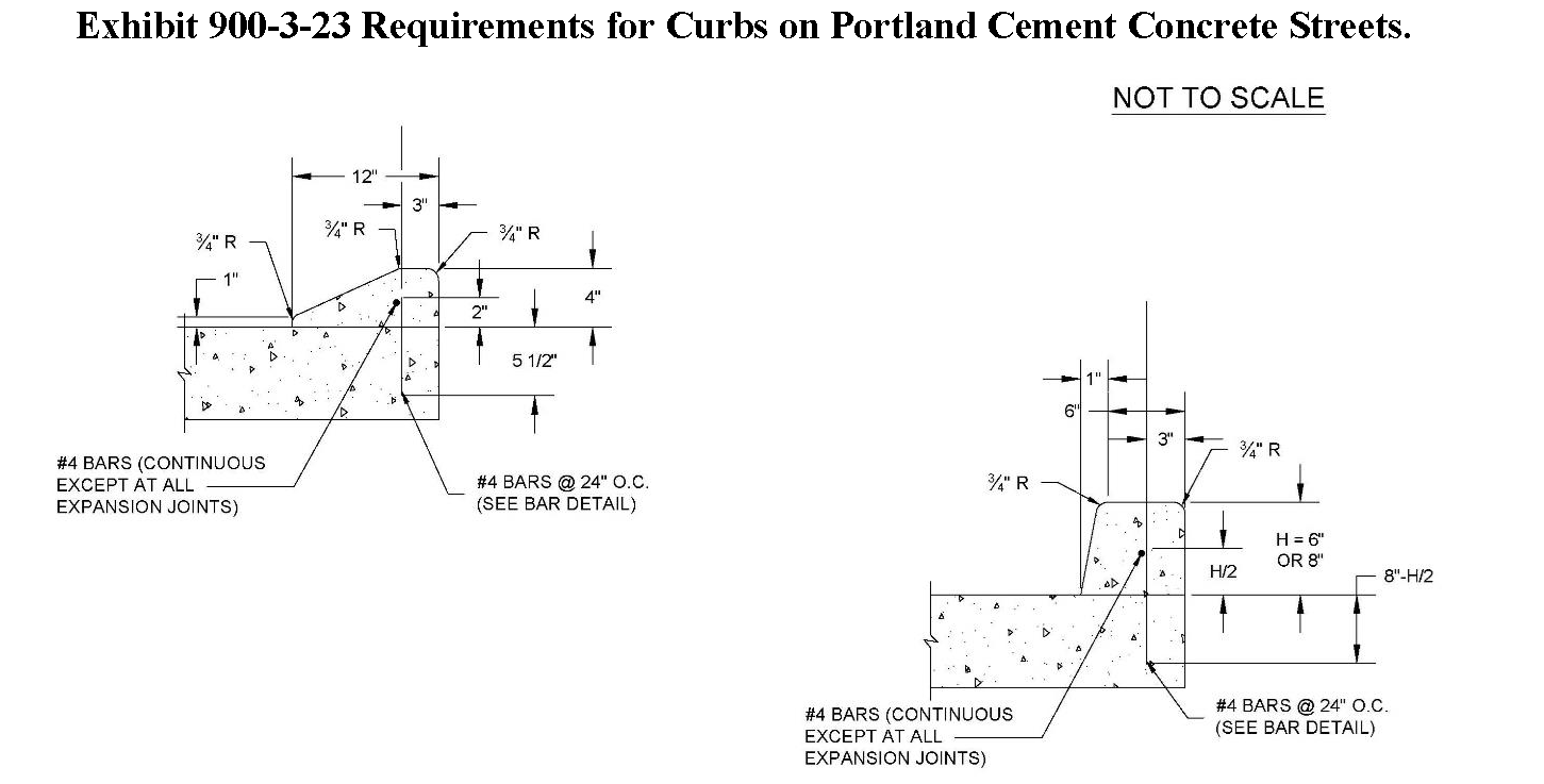
Rigid Pavement (Portland Cement Concrete Pavement). Curb and gutter streets for asphalt concrete pavement streets shall be constructed of Portland cement concrete conforming to the dimensions illustrated in Exhibit 900-3-23.
2.
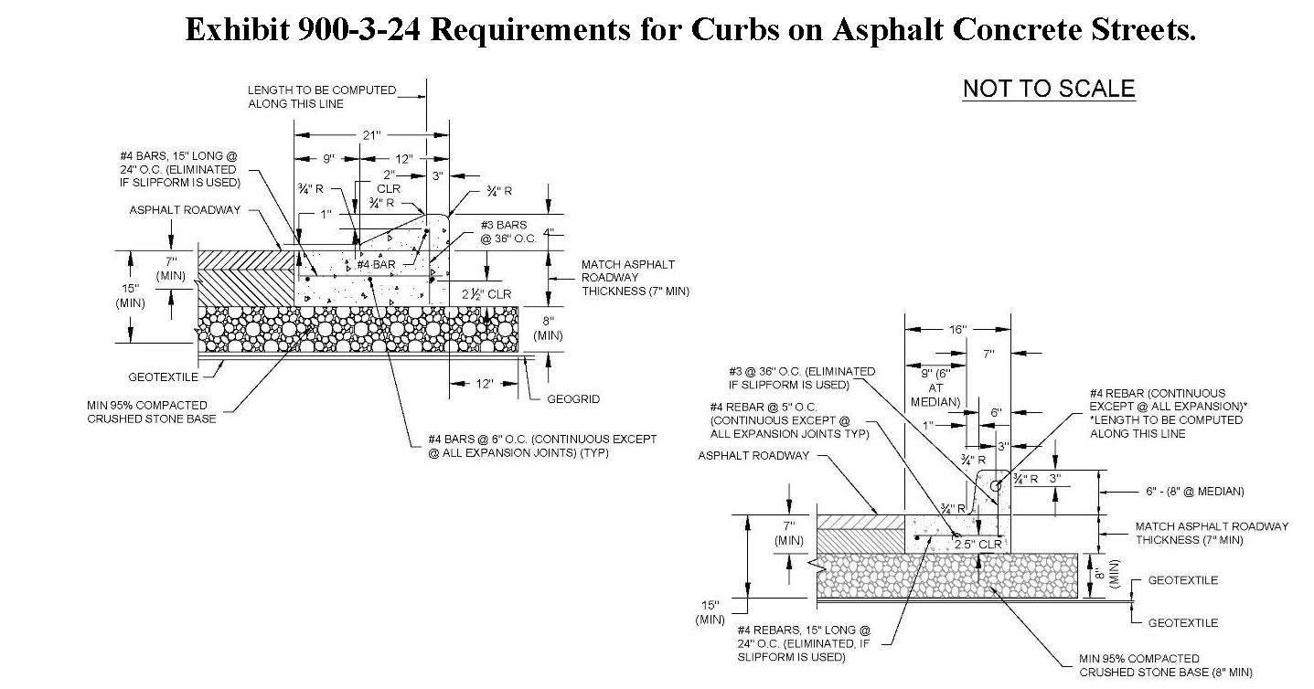
Flexible Pavement (Asphalt Concrete Streets). Curb and gutter streets for asphalt concrete pavement streets shall be a combination curb and gutter bottom constructed of Portland cement concrete conforming to the dimensions illustrated in Exhibit 900-3-24.
3.
Barrier Curb. Barrier curbs shall be provided at all intersections and all medians.
4.
Depressed Curb. The applicant may provide depressed curb or rollover/mountable curb at driveways.
5.
Rollover /Mountable Curb. Rollover curb shall be provided on all streets except where barrier curb is required.
6.
Slip-form paver with monolithic curb.
H.
Procedure for Approval, New Roadways Built by Applicants and Remain Private or Accepted into the Parish Roadway System.
1.
Upon approval of Final Plat and Construction Plan by the parish Planning and Zoning Commission, a geotechnical investigation, including a pavement design, shall be conducted by a licensed engineering firm registered in the State of Louisiana and retained by the applicant. The geotechnical report shall be submitted to the Department of Engineering for review and approval.
2.
The subsurface soil investigation shall have an adequate scope to sufficiently design the roadway embankment. The scope of the subsurface soil survey shall include, but not be limited to, the following:
a.
Soil borings shall be drilled to a depth of 6 feet at 500-foot intervals and not less than three borings per roadway section. At a minimum, the borings shall indicate the various soil stratifications and groundwater elevation.
b.
Laboratory testing shall be conducted on selected samples, including, but not limited to, moisture content, unconfined compressive strength, Atterberg limits determination and percent fines. Other laboratory testing and analysis, such as consolidation tests and embankment stability analysis for high fill areas, shall be performed, if necessary, at the discretion of the applicant's licensed professional engineer registered in the State of Louisiana and the Department of Engineering.
c.
The pavement design shall be based on the geotechnical investigation field data and laboratory test results, as well as a projected average daily traffic which includes the traffic resulting from the complete development of all land to be served by the subject roadway, including traffic forecast to be generated by the development, both internal and external to the development under consideration and in accordance with the pavement design requirements of this UDC.
I.
Procedure for Approval, Parish Acceptance of Private Roadway, Requirements for Accepting an Existing or Recently Constructed Private Roadway into the Parish Roadway System.
1.
Should an existing or recently built private roadway be considered for inclusion in the parish roadway system, the following geotechnical investigation shall be conducted by the applicant's licensed professional engineer registered in the State of Louisiana to verify compliance with the parish roadway design standards. This includes, but is not limited to, verification of pavement thickness as well as type and thickness of roadway base and sub-base.
a.
Roadway cores. Roadway cores shall be obtained at 500-foot intervals.
i.
For rigid pavement. The thickness shall be recorded and the compressive strength of the concrete shall be tested on the pavement cores for compliance with the parish roadway design requirements.
ii.
For flexible pavement. The thickness and density of the pavement cores shall be verified for compliance with the roadway design requirements.
b.
Soil borings. At the core locations, soil borings shall be conducted to a depth of at least 3 feet below the bottom of the pavement to verify the type and thickness of the pavement base and sub-base.
c.
Laboratory testing. Laboratory testing shall be conducted on selected samples from the roadway borings to classify the fill used for compliance with the roadway design and parish requirements.
d.
Testing and inspection reports. Available reports of testing and inspection, conducted during construction by the applicant, shall be provided to the Department of Engineering for review. This shall include testing and inspection reports of Portland cement concrete or asphaltic concrete, reports of field density tests conducted on the roadway base material and any underlying fill.
e.
Geotechnical investigations. Analysis of the pavement design for the existing roadway shall be based on the findings from the geotechnical investigation as well as the anticipated average daily traffic in the area.
f.
Acceptance. Acceptance of the roadway will be decided by the Department of Engineering based on the results of the pavement analysis. Furthermore, the parish may require funded certification of conformance through the establishment of performance and/or warranty letters of credit, to ensure that the applicant's obligation to construct the roads to the required standards is accomplished.
2.
Should the roadway be found not to be in compliance with the parish standards the roadway may be rejected or recommendations may be provided by the Department of Engineering to bring it up to the parish roadway standards. Furthermore, the parish may require a minimum of 2 years and a maximum of 5 years funded warranty letters of credit to ensure the integrity and durability of the street. The parish reserves the right to accept or reject streets that are deemed not up to the parish standards.
J.
Roadway Widening. The design for a widened roadway, when a part of a mitigation proposal or when required to bring existing roadways up to parish standards, shall take into consideration the anticipated new traffic load the road will be subjected to. At a minimum, the widened section of the road shall have a pavement section that is equivalent to the existing road or better if additional traffic load is anticipated based upon the results of the Traffic Impact Analysis. A subsurface investigation shall be conducted along the new section of the road that will be widened. The width of the widening shall be as necessary to meet the minimum lane width and shoulder requirements of this code. The scope of the subsurface soil investigation shall include, but not be limited to, the following:
1.
Soil borings shall be drilled to a depth of 6 feet at 500-foot intervals, but not less than 3 borings per roadway section. Pavement cores shall be obtained from the existing roadway alignment at 1,000-foot intervals with a minimum of 2 cores per roadway section. The existing thickness of the pavement and underlying base as well as the sub-base type shall be investigated and considered in the pavement design.
2.
Laboratory testing shall be conducted on selected samples, including, but not limited to, moisture content, unconfined compressive strength, Atterberg limits, and percent fines.
3.
The pavement design shall be based on the geotechnical investigation field data and laboratory test results as well as a projected average daily traffic including the anticipated future traffic for the widened road.
K.
Minimum Roadway Elevation. The minimum elevation for any street as measured at the lowest point of the travel lanes shall be at least 6.0' NAVD 88 GEOID03. This requirement may be adjusted when site conditions make compliance unsafe or infeasible as determined by the Department of Engineering.
L.
Private Drives Minimum Standards. Apart from a private drive accessing 1 lot or parcel, the following minimum construction standards shall apply:
1.
An owner who creates a private drive to access more than 1 lot or parcel, but no more than 5, shall dedicate through title, deed and or covenant, a perpetual servitude of access with a minimum width of 35 feet.
2.
The actual driving surface shall be a minimum of 20 feet in width with 2-foot shoulders on each side of the drive and 5.5 feet on each side of the shoulder devoted to ditching/drainage and or utilities.
3.
The drive shall be constructed with suitable compacted subbase materials and overlaid with an aggregate material (i.e., shell, gravel, limestone, three-course treatment, asphalt, concrete, etc.) that is acceptable to the Department of Engineering.
4.
A ditch or ditches shall be constructed on either one or both sides of a drive-in accordance to standard practices adopted by the Department of Engineering in order to provide adequate drainage.
5.
Any private drive created must be given a name and depicted on the Final Plat and Construction Plans, only after first obtaining approval for said name, in writing, from the St Tammany Parish Communications District 911 addressing officer.
6.
Plans for the construction of the private drive and drainage must be performed by a licensed professional engineer registered in the State of Louisiana and submitted to the Department of Engineering for review and approval prior to the initiation of work.
7.
After the private drive has been constructed and drainage improvements made, the responsible owner shall submit to the Department of Engineering an as-built plan showing conformance to the previously approved plans.
8.
Following submittal of the as built plan, the applicant shall contact the Department of Engineering to schedule an inspection.
9.
Once the private drive has been constructed and all drainage improvements completed and approved by the Department of Engineering, then, and only then, can the minor subdivision be recorded for public record with the Clerk of Court's office and the lots sold or donated.
10.
The owner selling or donating lots or parcels to others shall be solely responsible for establishing a maintenance agreement specifying the entity or entities whom shall provide maintenance and upkeep for the private drive. Copies of the agreement must be provided to the Departments of Engineering and Planning and Development for their files.
11.
A private drive cannot under any circumstances be dedicated as a public right-of-way unless said drive is upgraded to meet the definition and standards of a "private street" or "public street" pursuant to this chapter.
12.
Only one main private drive shall be permitted per each minor subdivision.
Sec. 900-3.4 - Construction requirements for streets.
A.
Clearing and Grubbing for Street Construction.
1.
The applicant shall provide for the clearing, grubbing, removing and disposing of vegetation and debris within the limits of the right-of-way and easement areas shown on the approved subdivision plans, except such items that are designated to remain.
2.
This shall include but not be limited to cutting trees, logs, brush, stumps and debris; excavating and removing stumps, roots, submerged logs, snags and other vegetative or objectionable material; disposing of removed material in a legal manner and cleaning the area.
3.
The subdivision plans shall indicate items to remain. The applicant shall preserve the items designated to remain.
4.
Trees shall be removed without damaging items marked to remain. In case of damage to bark, trunks, limbs or roots of vegetation marked to remain, the applicant shall repair such damage by horticultural and tree surgery practices published by the American Association of Nurserymen (AAN).
5.
Clearing and grubbing shall be done within the construction limits and to a point in fills 15 feet beyond the toes of fore slopes and in cuts 15 feet beyond the tops of backslopes, when width of right-of-way permits, or to the limits shown on the plans; also from areas required for outfall ditches and channel changes. Trees, stumps, roots and other protruding vegetative obstructions not designated to remain shall be cleared and grubbed.
6.
Undisturbed stumps, roots and nonperishable solid objects which will be a minimum of one foot below the subgrade or slope of embankments will be permitted to remain provided they do not extend more than six inches above the original ground line or low water level.
7.
Except in areas to be excavated, stump holes and other holes left from clearing and grubbing shall be backfilled with usable soil which shall be thoroughly compacted.
B.
Removal of Structures and Obstructions. The applicant shall provide for the removal and legal disposal of pavements, sidewalks, curbs, gutters, and other obstructions not designated or permitted to remain.
C.
Preparation of Subgrade.
1.
The applicant shall provide all work to cause all roadway subgrade to conform to the lines and elevations shown on the approved plans.
2.
The surface of the finished subgrade shall be parallel to and conform to the cross section of the roadway pavement.
3.
Berms, ridges of earth, or other material that will interfere with the immediate discharge of water to the side of the crown shall not be left on the subgrade. The subgrade shall be maintained free from ruts so that it will, at all times, drain properly with no standing water.
4.
Stumps and roots exposed in the preparation of the subgrade shall be either removed or excavated to a depth of not less than foot below the subgrade and the resultant excavation filled with usable soil and compacted.
5.
When the subgrade strength is sufficiently strong to support construction traffic without rutting, heavy equipment may be used.
6.
The subgrade shall be uniformly compacted by light weight roller (5 tons). When the subgrade is in a wet condition, it shall be allowed to dry until the material is within reasonable limits of optimum moisture before compaction is attempted.
7.
Upon completion of compaction by light weight roller the exposed subgrade areas shall be properly proof rolled to verify suitability of subgrade to receive the base course.
8.
Once the roadway alignment is stripped and undercut to the required subgrade elevation, the roadway subgrade shall be proof rolled using a single or a tandem axle dump truck or similar heavily loaded rubber-tired vehicle weighing about 20 tons. Soils which are observed to rut or deflect under the moving load shall be undercut and replaced with compacted structural fill, disked open to dry or treated to form a stable non-yielding subgrade prior to fill placement. Proof rolling the roadway subgrade shall be witnessed by the parish inspection personnel or their representative prior to proceeding with fill placement. The approval of the subgrade is valid for 48 hours. Therefore, the subgrade shall be protected and covered with fill as soon as possible. Should the subgrade be exposed to excessive amount of precipitation, re-approval of the subgrade will be required.
D.
Base and Subbase Course.
1.
The applicant shall place, shape, and compact a base or subbase course on a prepared subgrade in accordance with these specifications and in close uniformity with the lines, grades, thicknesses, typical cross sections, and materials shown on the approved plans.
a.
Subbase under asphaltic concrete pavements and base under Portland cement concrete pavements shall be required when the natural in situ subgrade soil, as determined by soil tests, is not an AASHTO A-4 or better material. When the subgrade natural ground is an A-4 material, the maximum liquid limit shall be 40 and the maximum plasticity index shall be 20, otherwise subbase material is required under asphaltic pavements and base material is required under concrete pavements.
2.
Recycled Portland Cement Concrete shall be 100 percent crushed Portland Cement Concrete and will be permitted in combination with an approved stone for base course. After being crushed, the recycled Portland Cement Concrete or the combination of stone and recycled Portland Cement Concrete shall conform to the following gradation:
Exhibit 900-3-25.
3.
Stone shall consist of 100 percent stone and shall conform to the following gradation:
Exhibit 900-3-26.
a.
The base and subbase shall be constructed so that contamination, segregation, soft spots, wet spots and other deficiencies are prevented.
b.
The applicant shall construct the finished base course with a smooth, uniform, closely knit surface, free from ridges, waves, laminations or loose material.
c.
Subbase and base course shall be compacted to 95% of maximum dry density as determined by ASTM D698.
E.
Asphaltic Concrete Pavement Production. Asphaltic concrete pavement mixtures shall be produced in accordance with LaDOTD requirements.
F.
Asphaltic Concrete Pavement Placement. The applicant shall furnish and construct one or more courses of Superpave asphaltic concrete mixture applied hot in conformance with these specifications and in conformity with the lines, grades, thicknesses, and typical sections shown on the approved plans. The mixture shall consist of aggregates and asphalt with additives combined in proportions which meet the requirements of this section. These requirements are applicable to asphaltic concrete wearing, binder, and base course mixtures of the plant mix type.
1.
Substitutions will be allowed for mixes without requiring approval of the Director of Department of Engineering only as follows:
a.
Changes in design level will not be allowed on the roadway.
b.
Wearing course may be substituted for binder course.
c.
Binder course may be substituted for base course.
d.
0.5" Wearing Course may be substituted for Incidental Paving, Level A.
2.
When any substitution is made, all specification requirements for the mixture used shall apply with the following exceptions. When wearing course is substituted for binder course, RAP will be allowed in accordance with binder course requirements. Design of mixtures shall comply with the following:
Exhibit 900-3-27 Asphalt Concrete General Criteria.
1 May be used for minor mix uses
2 Mixtures designated at Level 1F and 2F shall meet the requirements of Level 1 and 2, respectively. Additionally, Level 1F and 2F shall meet the friction rating requirements for travel lane wearing courses.
3 N/A.
4 Air voids mix design target is a 3.5 percent.
5 Mix design minimum VFA is 72.0%, Mix design minimum VFA for PG76-22rm is 75.0%, and 71% for 25 mm NMS mixtures.
6 For Level 1 mixtures, Ninitial shall be 91.0% max. For Level A mixes, Ninitial shall be 92.0% max.
7 N/A
8 Absolute minimum of lift thickness across width equal to 1/2 inch lower than minimum lift thickness.
9 Also must meet a maximum of 25 percent at a 3:1 ratio.
3.
Quality assurance requirements and design procedures shall be as specified in the latest edition of the LaDOTD's publication entitled "Application of Quality Assurance Specifications for Asphaltic Concrete Mixtures."
4.
The applicant shall keep accurate records, including proof of deliveries of materials for use in asphaltic concrete mixtures. Copies of these records shall be furnished to the Department of Engineering upon request. Material shall conform to the following requirements:
a.
Asphalt cement shall be a product listed on the LADOTD AML at the time of the production of the mixture.
b.
Silicone and Anti - Strip Additives shall be products listed on the AML at the time of the production of the mixture.
c.
Aggregates shall conform to the gradations established herein and shall be listed on the LADOTD AML at the time of the production of the mixture.
5.
Mixture Levels. Mixture levels shall comply with the following table:
Exhibit 900-3-28 Mixture Levels.
6.
Asphalt. The asphalt cement grades used shall be as specified in the table below using the design traffic load levels determined in accordance with this UDC.
Exhibit 900-3-29 Asphalt Cement Usage.
1 For single lift overlay, match grade of overlay.
2 Asphaltic mixtures using substitutions are required to meet all design requirements for the original design level
3 Not Used
4 When more than 25% RAP is used, PG 58-28 is required.
a.
Base course mixtures containing 20 to 30 percent RAP shall use PG 58- 28 asphalt cement.
b.
The applicant shall reduce the amount of asphalt cement in the plant's storage or working tanks to 20% or less before adding another grade of asphalt cement or asphalt cement from another source.
i.
Silicone. Silicone additives, when needed, shall be dispersed into the asphalt by methods and in concentrations given in the LaDOTD AML.
ii.
Anti-Strip (AS). An anti-strip additive shall be added at the minimum rate of 0.5 percent by weight (mass) of asphalt cement and thoroughly mixed in-line with the asphalt cement at the plant. Additional anti-strip shall be added up to 1.2 percent by weight.
iii.
Hydrated Lime. Hydrated lime additive may be incorporated into all asphaltic concrete mixtures at the rate specified in the approved job mix formula. The minimum rate shall not be less than 1.5 percent by weight of the total mixture. Hydrated lime additive shall be added to and thoroughly mixed with aggregates.
iv.
Aggregates. Aggregates shall meet the requirements of the tables below and shall be listed on the LaDOTD AML at the time of their incorporation into the mixture.
Exhibit 900-3-30.
v.
Recycled Portland Cement Concrete. Recycled Portland Cement Concrete will be allowed in base courses with a maximum of 70 percent recycled Portland cement concrete by weight combined with new aggregates. Recycled concrete shall be crushed and screened into a minimum of 2 stockpiles composed of different sized aggregates separate from other materials at the plant. Recycled concrete shall be dried as required for new aggregates.
vi.
Reclaimed Asphaltic Pavement (RAP). Reclaimed asphaltic pavement shall be stockpiled separate from other materials at the plant and will be subject to approval prior to use. Such stockpiles shall be uniform and free of soil, debris, foreign matter, and other contaminants. Reclaimed materials that cannot be broken down during mixing or that adversely affect paving operations shall be screened or crushed to pass a 2-inch sieve prior to use.
vii.
Mineral Filler. Mineral filler listed on the LaDOTD AML may be used in all mixtures.
viii.
Warm Mix Additives. When used, add only warm mix chemical additives listed on the AML. Foaming is allowed.
ix.
Friction Ratings for coarse aggregates shall be determined in accordance with the requirements of this code. Aggregates shall have a friction rating of I or II for all mixtures.
7.
The applicant shall be responsible for design, production, transportation and laydown of mixtures. Work shall meet the requirements of this Section and be subject to acceptance by the Department of Engineering.
8.
The applicant shall exercise quality control over materials and their assembly, design, processing, production, hauling, laydown and associated equipment. Quality control is defined as the constant monitoring of equipment, materials and processes to ensure that mixtures produced and laid are uniform, are within control limits, and meet specification requirements. When these specifications are not being met and satisfactory control adjustments are not being made, operations shall be discontinued until proper adjustments and uniform operations are established. Control shall be accomplished by a program independent of, but correlated with, acceptance testing and shall ensure that the requirements of the job mix are being achieved and that necessary adjustments provide specification results.
9.
Validation. Validation will be based on the first lot test results. All code criteria must be met for production to continue.
10.
Weather Limitations. Asphaltic concrete mixtures shall not be applied on a wet surface or when ambient temperature is below 40 F, except that material in transit, or a maximum of 50 tons in a surge bin or silo used as a surge bin at the time plant operation is discontinued may be laid; however, mixture laid shall perform satisfactorily and meet specification requirements. Inclement weather will be sufficient reason to terminate or not begin production.
a.
When base course materials are placed in plan thicknesses of 2 3/4 inches or greater, these temperature limitations shall not apply provided all other code requirements are met.
11.
Surface Preparation. The surface to be covered shall be approved by the Director of Department of Engineering prior to placing mixtures. The applicant shall maintain the surface until it is covered.
12.
Cleaning. The surface to be covered shall be swept clean of dust, dirt, caked clay, caked material and loose material by revolving brooms or other mechanical sweepers supplemented with hand equipment as directed. When mixtures are to be placed on Portland cement concrete pavement or overlaid Portland cement concrete, the applicant shall remove excess joint filler from the surface by an approved burning method. The applicant shall remove any existing raised pavement markers prior to asphaltic concrete overlay operations.
a.
When brooming does not adequately clean the surface, the applicant shall wash the surface with water in addition to brooming to clean the surface.
13.
When liquid asphalt is exposed to traffic for more than 2 calendar days, becomes contaminated, or degrades due to inclement weather, the liquid asphalt shall be reapplied at the initial recommended rate at the expense of the applicant.
G.
Applying Asphaltic Materials.
1.
Existing Pavement Surfaces. Before constructing each course, an approved asphaltic tack coat shall be applied in accordance with the requirements of this Code. The applicant shall protect the tack coat and spot patch as required.
2.
Raw Aggregate Base Course and Raw Embankment Surfaces. The applicant shall apply an approved asphalt prime coat to unprimed surfaces or protect in-place prime coat and spot patch as required with asphaltic prime coat in accordance with the requirements of this code.
3.
Other Surfaces. Contact surfaces of curbs, gutters, manholes, edges of longitudinal and transverse joints, and other structures shall be covered with a uniform coating of an approved asphaltic tack coat conforming the requirements of this code before placing asphalt mixtures.
4.
Longitudinal Joints. Longitudinal joints shall be constructed by setting the screed to allow approximately 25 percent fluff and overlapping the paver approximately 2 inches onto the adjacent pass. Prior to rolling, the overlapped mix shall be pushed back to the uncompacted side, without scattering loose material over the uncompacted mat, to form a vertical edge above the joint. The vertical edge shall then be compacted by rolling to form a smooth, sealed joint. Longitudinal joints in one layer shall offset those in the layer below by a minimum of 3 inches; however, the joint in the top layer shall be offset 3 inches to 6 inches from the centerline of pavement when the roadway comprises two lanes of width or offset 3 inches to 6 inches from lane lines when the roadway is more than two lanes. The narrow strip shall be constructed first.
5.
Adjacent Paving Strips. Where adjacent paving strips are to be placed, the longitudinal edge joint of the existing strip shall be tacked.
6.
Transverse Joints. Transverse joints shall be butt joints formed by cutting back on the previously placed mixture to expose the full depth of the lift. An approved 10-foot static straightedge shall be used to identify the location at which the previously placed mixture is to be cut back to maintain no greater than a 1/8 inch deviation in grade. The cut face of the previously placed mat shall be lightly tacked before fresh material is placed. The screed shall rest on shims that are approximately 25% of plan thickness placed on the compacted mat or the screed shall be set at a distance that is 25% of plan thickness above the mat surface. Transverse joints shall be formed by an adequate crew. Transverse joints shall be checked by the applicant for surface tolerance using a stringline extended from a point 10 feet before the joint to a point approximately 40 feet beyond the joint. Any deviation in grade from the stringline in excess of 3/16 inch for roadway wearing courses and 1/4 inch for other courses shall be immediately corrected prior to the paving operation continuing beyond 100 feet of the transverse joint. Additionally, the transverse joint shall meet the surface tolerance requirements of this Code. The applicant shall make necessary corrections to the joint before continuing placement operations. Transverse joints in succeeding lifts shall be offset at least 2 feet.
7.
Sawing and sealing of joint in an asphaltic concrete overlay. When new concrete pavement or existing concrete foundation is to be overlaid with asphaltic concrete, joints shall be sawed or formed and sealed.
8.
Sawed joints. Saw cut shall be made in the overlay at the locations of all transverse and longitudinal joints in the concrete pavement. The sawed joints will have a minimum of 1/8" wide by 1" deep. The applicant shall clean and dry the saw cut before applying sealant in accordance with the requirements of this Code.
9.
Hauling, paving, and finishing. Mixtures shall be transported from the plant and delivered to the paver at a temperature no cooler than 25 F below the lower limit of the accepted job mix formula. The temperature of the mix going through the paver shall not be cooler than 250F.
10.
Segregation. When segregation occurs, haul trucks shall be loaded with a minimum of three drops of mix, the last of which shall be in the middle.
11.
Thickness. Each lift of asphaltic mixture shall be placed in accordance with the lift thickness as shown on the approved plans. When no lift thickness is specified, binder and wearing course mixtures shall be placed in lifts not exceeding 2 inches plan thickness. Base course mixtures shall be placed in lifts of such thickness that all specification requirements are met.
12.
Depressions in initial layer. With the approval of the Department of Engineering, motor patrols may be used to fill isolated depressions in the initial layer, provided this construction does not result in unsatisfactory subsequent lifts.
13.
Coordination of Production. The applicant shall coordinate and manage plant production, transportation of mix and placement operations to achieve a high-quality pavement and shall have sufficient hauling vehicles to ensure continuous plant and roadway operations. The Department of Engineering shall have the authority to order a halt to operations when sufficient hauling vehicles are not available.
14.
Protection from traffic. Pavement shall be protected from traffic until it has sufficiently hardened to the extent the surface is not damaged.
15.
Compaction. After placement, mixtures shall be uniformly compacted by rolling while still hot, to at least 92% of Theoretical Maximum Specific Gravity (%Gmm) as determined by AASHTO T209 Method C. If continuous roller operation is discontinued, rollers shall be removed to cooler areas of the mat, where they will not leave surface indentations. The use of steel wheel rollers which result in excessive crushing of aggregate will not be permitted.
16.
Surface. The surface of mixtures after compaction shall be smooth and true to cross slope and grade within the tolerances specified. Mixtures that become loose, broken, contaminated or otherwise defective shall be removed and replaced with fresh hot mixture compacted to conform with the surrounding mixture.
17.
After finish rolling, newly finished pavements shall have a uniform, tightly knit surface free of cracks, tears or other deficiencies. Deficiencies shall be corrected at the expense of the applicant and the applicant shall adjust operations to correct the problem. This may require the applicant to adjust the mix or furnish additional or different equipment.
H.
Roadway Acceptance.
1.
Density. Acceptance testing for pavement density will be conducted by the Independent Testing Laboratory. One pavement core for each mix use shall be taken from each sublot within 72 hours after placement. Sampling shall be performed by the independent testing laboratory using the random number tables shown in DOTD TR 605. When the sampling location determined by random sampling falls within areas that are to be replaced, within 1 foot of the pavement edge, or within 5 feet of a transverse joint; another sampling location will be determined. Samples will be drilled by the Applicant at the locations determined by the Independent Testing Laboratory. The Applicant shall transport the cores to the asphalt plant for testing by the Independent Testing Laboratory. The Applicant's representative will inspect the cores upon delivery to the plant and before any testing is performed on the core. Any damaged cores or cores that are less than 1 3/8"; can be rejected at that time and a new sampling location must be determined and the core re-drilled. The removed pavement shall be replaced with hot or cold mixture and refinished during the workday the coring is performed. Cores less than 1 3/8" thick shall not be used as pavement samples for payment determination. The average density of all cores for each lot shall be greater than 92% of Maximum Theoretical Gravity (TR 327). Roadway density will be calculated using the lot average for Maximum Theoretical Gravity.
2.
Lot sizes. A lot is a segment of continuous production of asphaltic concrete mixture from the same job mix formula produced for a given job at an individual plant. A standard lot will be defined as:
a.
2000 tons production
b.
Partial lots will require testing at the frequency of one test per 500 tons, and portion thereof.
3.
Each lot will be sub-divided into 4 equal sublots based on expected production. Testing will be conducted as follows:
a.
First Sublot.
i.
Tests will be performed on aged specimens compacted to N-design as follows:
(A)
Percent Voids
(B)
Percent VFA
(C)
Percent VMA
ii.
Theoretical Maximum Specific Gravity (Gmm)
iii.
Gradation, AC Content and Percent Crushed
iv.
Aged or un-aged specimens compacted to N-maximum as follows:
(A)
Percent Gmm at N-initial
(B)
Percent Gmm at N-Maximum
b.
Second Sublot.
i.
Theoretical Maximum Specific Gravity (Gmm)
ii.
Aged or un-aged specimens compacted to N-maximum as follows:
(A)
Percent Gmm at N-initial
(B)
Percent Gmm at N-Maximum
c.
Third Sublot.
i.
Tests will be performed on aged specimens compacted to N-design as follows:
(A)
Percent Voids
(B)
Percent VFA
(C)
Percent VMA
ii.
Theoretical Maximum Specific Gravity (Gmm)
iii.
Gradation, AC Content and Percent Crushed
iv.
Aged or un-aged specimens compacted to N-maximum as follows:
(A)
Percent Gmm at N-initial
(B)
Percent Gmm at N-Maximum
d.
Fourth Sublot.
i.
Theoretical Maximum Specific Gravity (Gmm)
ii.
Aged or un-aged specimens compacted to N-maximum as follows:
(A)
Percent Gmm at N-initial
(B)
Percent Gmm at N-Maximum
4.
Tests for Theoretical Maximum Specific Gravity, Voids, VMA and VFA shall be conducted by the Independent Testing Laboratory. If lot averages (minimum two samples) exceed tolerances listed within this code, an adjustment must be made to the mix by the Applicant to bring the mix back within tolerance. If two consecutive lots are out on the same parameter, production must be halted and the mix re-designed.
5.
Tests for Gradation, AC Content, and Percent Crushed and for aged or un-aged specimens compacted to N-maximum shall be conducted by the Applicant's Quality Control representative. If lot averages (minimum two samples) exceed tolerances listed in Table C502-2, an adjustment must be made to the mix by the Applicant to bring the mix back within tolerance. If two consecutive lots are out on the same parameter, production must be halted and the mix re-designed.
I.
Asphaltic Tack Coat.
1.
The applicant shall prepare and treat asphaltic or concrete surfaces with asphaltic material in accordance with these specifications and in conformity with the lines shown on the approved plans.
2.
Tack coat shall be a modified asphalt emulsion (Grade SS-1, SS-1H or CMS-2) or a modified asphalt emulsion (Grade CRS-2P, CRS-2L, SS-1P or SS-1L) listed on the LaDOTD AML at the time of its application.
3.
Asphaltic tack coat shall not be applied on a wet surface or when the ambient air temperature is below 40 F.
4.
The Applicant shall provide equipment for applying asphaltic material and preparation of the surface to be tacked. Equipment shall conform to the requirements of this Code. A hand-held pressure nozzle may be used for tack coat application in lieu of the spray bar/tachometer combination for irregular sections or short sections of 1500 feet or less.
5.
The surface shall be cleaned by sweeping or other approved methods. Edges of existing pavements which will form joints with new pavement shall be satisfactorily cleaned before tack coat is applied. Asphalt shall be uniformly applied to a clean dry surface with no bare areas, streaks, or puddles with an asphaltic distributor at a rate in accordance with the table below.
Exhibit 900-3-31 Asphalt Tack Coats.
1 Rates are minimum rates of undiluted asphalt emulsion.
2 Minimum rate for hot applied non-tracking tack (NTHAP) is 0.08 gal/sq yd for all surface types
J.
Asphaltic Prime Coat.
1.
The applicant shall prepare and treat surfaces with asphaltic material in conformance with these requirements of this Code and in conformity with lines shown on the plans or established in the field.
2.
Prime coat shall be cutback asphalt Grade MC-30, MC-70, or AEP Emulsified Asphalt listed on the LaDOTD AML at the time of its use.
3.
Asphaltic materials shall not be applied on a wet surface or when ambient air temperature is less than 35 F in the shade.
4.
The applicant shall provide the necessary equipment for proper construction of the work. Equipment shall be approved before construction begins and shall be maintained in satisfactory working condition. Equipment shall conform to the requirements of this Code.
5.
The surface to be coated shall be shaped to required grade and section shall be free from ruts, corrugations, segregated material or other irregularities, and shall be compacted to required density. Delays in priming may necessitate reprocessing or reshaping to provide a smooth, compacted surface
6.
Prime coat shall extend 6 inches beyond the width of surfacing shown on the approved plans. The prime coat shall not be applied until the surface has been satisfactorily prepared and is dry.
7.
Prime coat shall be applied at the rates and temperatures shown in the table below. Quantities of prime coat shall not vary from that shown the table below.
Exhibit 900-3-32 Prime Coat Application Requirements.
8. After prime coat has been applied it shall cure for a minimum of 24 hours before the surfacing is placed. The applicant shall keep traffic off the surface until the prime coat has properly cured, unless otherwise permitted.
9.
If traffic is permitted, the applicant may be required to spread approved granular material, as directed, over the prime coat at the expense of the applicant.
10.
The prime coat shall be maintained intact. When required, the primed surface shall be thoroughly cleaned prior to the placement of surfacing.
11.
Where the prime coat has failed, the failed area shall be cleaned and be recoated with prime coat at no direct pay. When the prime coat is generally unsatisfactory, the applicant shall reprime the unsatisfactory surface at the expense of the applicant.
J.
Cold Planing/Milling of Asphalt Pavement.
1.
Where required by the approved plans, the applicant shall remove asphalt pavement to the depth, width, grade, cross-slope and typical sections shown on the approved plans by milling.
2.
Thirty foot (minimum) traveling reference plane shall be used on each pass of the milling machine. A shoe device to match the curb may be used when directed. The reference plane shall be placed on the best available adjacent surface.
3.
When the entire roadway width has not been milled to a flush surface by the end of a work period resulting in a vertical or near vertical longitudinal face exceeding 2 inches in height, this longitudinal face shall be sloped. Transverse faces present at the end of a work period shall be beveled. Provisions shall be made at drives and turnouts to maintain local traffic.
4.
Asphaltic concrete next to structures that cannot be removed by the milling machine shall be removed by other acceptable methods.
5.
Pavement surfaces resulting from milling operations shall be of uniform texture, grade and cross-slope and free from loose material. Planed surfaces not meeting these requirements shall be re-milled at the expense of the applicant. No uneven, undulating surfaces will be accepted. The applicant shall provide drainage of planed areas by cutting through the shoulder to the ditch.
6.
The milling operation shall not precede the subsequent paving operation by more than 10 calendar days. This time may be extended by the Department of Engineering upon request by the applicant if extensive joint repairs or patching is required. For single lift overlays requiring shoulder stabilization, the milling operation shall not precede the subsequent paving operation by more than 30 days.
7.
On roadways that are open to traffic, pavement striping removed by milling shall be replaced with temporary pavement markings at the end of each day's milling operations in accordance with the requirements of this Code.
8.
Unless otherwise provided for within the permit, surfacing material removed by milling shall become the property of the applicant and shall be disposed of in accordance with local, State, and Federal Law. When specified on the permit, a portion or all of the surfacing material removed by milling will be retained by the Parish and shall be hauled by the applicant to the specified location and stockpiled as directed. Excess material shall then become the property of the applicant and shall be disposed of in accordance with local, State, and Federal Law.
a.
Required joint repairs shall be made after milling. Pavement patching shall be completed before milling. When additional areas requiring patching are exposed by milling operations, such additional patching shall be performed after milling. Pavement patching shall be in accordance with the requirements of this code.
9.
Except when milling reaches an existing concrete base layer, the surface tolerance requirements of the milled surface shall meet the requirements for binder course as required by this code.
K.
Asphalt Pavement Patching, Widening, and Joint Repair.
1.
The applicant shall provide for patching, widening and joint repair of existing asphaltic concrete pavements in accordance with the requirements of this Code and in conformity with the lines, grades and typical sections shown on the approved plans or as directed. Asphaltic concrete shall be used for patching, widening, and joint repair.
2.
Asphaltic concrete for patching and widening may be any type mixtures listed within this Code, except that 1/2 inch nominal maximum size mixtures shall not be used. Asphaltic concrete for joint repair shall be Superpave Asphaltic Concrete (Level A) complying with the requirements of this Code. Tack coat shall comply with the requirements of this Code.
3.
The applicant shall remove existing surfacing and base materials and perform all required excavation for patching and widening. When through traffic is maintained, the applicant shall complete the replacement of pavement, place the widening material, or fill and compact open areas or trenches at the end of each day's operations. Excavation and compaction of the subgrade shall be in accordance with the approved plans. The subgrade shall be compacted uniformly.
4.
Existing surfacing and excess excavation shall be disposed of beyond the right-of-way in accordance local, State, and Federal law.
5.
Prior to joint repair, contact surfaces of existing pavement shall be cleaned and a thin, uniform asphalt tack coat applied prior to placing asphaltic mixture in the joint. Patching and widening with asphaltic concrete shall conform to the requirements of this Code, except that priming of the subgrade will not be required.
6.
Contact surfaces of pavement shall be cleaned, and a uniform coat of asphalt tack coat applied before placement of asphaltic concrete.
7.
Patches shall not be overlaid for a minimum of 5 calendar days Spreading, finishing and compaction of asphaltic concrete shall leave the surface smooth and level with, or slightly above, the edge of existing pavement.
8.
To provide lateral support, the applicant will be permitted to construct temporary berms of excavated material against the outside edge of widening strips prior to rolling.
L.
Portland Cement Concrete Pavement Production and Placement.
1.
The applicant shall construct Portland roadway pavement in substantial conformance with these requirements and in conformity with the locations, lines, grades, slopes, thickness, sections, and strength shown on the approved plans and included herein.
2.
The pavement thickness shall be dependent upon soil properties, traffic type and frequency as provided for by the requirements of this Code.
3.
Portland cement shall be a product listed on the LaDOTD AML and conform to the requirements of ASTM C 150, Type I or Type II.
4.
Aggregates. Fine aggregate shall be a clean natural sand conforming to the requirements of ASTM C 33. Coarse aggregate shall be clean, hard, durable gravel, crushed stone or crushed concrete conforming to the requirements of ASTM C 33, Gradation No. 467 or 57.
a.
Admixtures. If used, air entraining admixtures shall conform to the requirements of ASTM CZ60 and shall be listed on the LaDOTD AML. Water reducing admixtures and water reducing, retarding admixtures shall conform to the requirements of ASTM C 494 and shall be listed on the LaDOTD AML. Super plasticizers shall conform to the requirements of ASTM C 494, Type F or G, and shall be listed on the LaDOTD AML.
b.
Water used in mixing concrete shall be potable and fit for human consumption.
c.
Fly ash shall meet the requirements of ASTM C 618, Class C. Fly ash is approved for use in pavements only and not in structures.
d.
Ground granulated blast furnace slag shall meet the requirements of ASTM C 989.
5.
Joint Fillers.
a.
Preformed joint fillers may be any of the following type:
i.
Resilient Bituminous Type. Comply with AASHTO M 213.
ii.
Wood Fillers. Use clear heart redwood for bottom boards. Use any type of wood which is free from defects and meets dimensional requirements for top boards. Occasional medium surface checks will be permitted provided the board is free of defects that will impair its usefulness. Boards may not vary from specified dimensions in excess of the following tolerances: Thickness, -0," +1/16"; Depth, +/- 1/8"; Length, +/-1/4." The load required to compress the material in an oven-dry condition to 50 percent of its original thickness may not exceed 1750 psi.
iii.
Bituminous Type. Comply with ASTM D994
iv.
Asphalt Ribbon. Use filler consisting of preformed strips of bitumen and inert filler material conforming to the requirements in the table below. The tensile strength is determined by pulling a 25-by-150-mm sample at a 500-mm/min separation rate. Use material that is resistant to cracking, tearing, or permanent deformation under normal handling and installation procedures. Use material that is sufficiently rigid to enable it to form a straight joint. Use backer material of the appropriate size complying with ASTM D5249, Type 3.
b.
Poured and extruded sealants shall be any of the following:
i.
Hot Poured Rubberized Asphalt Type. Comply with ASTM D6690, Type 2. Use material listed on the Approved Materials List. Use backer materials of the appropriate size complying with ASTM D5249, Type 1.
ii.
Polyurethane Sealant. Use either a 1- or 2-component, pourable or extrudable sealant, with required primers and backer material. Use material that cures to a solid rubber-like material able to withstand both tension and compression. Use material listed on the Approved Materials List. Use a backer material of the appropriate size complying with ASTM D5249, Type 2 without the heat resistant requirement or Type 3.
iii.
Silicone Sealant, Single Component. Comply with ASTM D5893. Use a system listed on the Approved Materials List
iv.
Silicone Sealant, Two Component—Rapid Cure. Comply with ASTM D5893 and meet the requirements for single component sealants when mixed and prepared in accordance with the manufacturer's recommendations. Use material listed on the Approved Materials List. Use a backer material of the appropriate size conforming to ASTM D5249, Type 3.
v.
Preformed Elastomeric Compression joint sealers shall be material listed on the Approved Materials List. Use material with an uncompressed depth that is equal to or greater than the uncompressed width of the seal. The actual width of the seal may not be less than the nominal width of the seal. Use system complying with ASTM D2628, except that the ozone resistance may be determined by the bent loop test method.
c.
Metal parting strips used to form keyed joints shall be 16-gauge galvanized steel.
6.
Reinforcing bars.
a.
Reinforcing bars shall conform to at least one of the following:
i.
"Specifications for Billet-Steel Bars for Concrete Reinforcement" (ASTM A 615).
ii.
"Specifications for Deformed Rail-Steel Bars for Concrete Reinforcement" (ASTM A 616).
iii.
"Specifications for Deformed Rail-Steel Bars for Concrete Reinforcement with 60,000 psi Minimum Yield Strength."
iv.
"Specifications for Axle-Steel Bars for Concrete Reinforcement" (ASTM A 160).
v.
Deformations for deformed bars shall conform to "Specifications for Deformations for Deformed Steel Bars for Concrete Reinforcement" (ASTM A 305).
b.
When placed, all reinforcement shall be free from dirt, oil, paint, grease, mill scale, loose or thick rust, or other deleterious substances. When bending is required, it shall be accurately done. All reinforcement shall be placed in the exact positions shown on the plans. Reinforcement shall be securely held in position by wiring and blocking it from the forms and by wiring it together at intersections so that it will not be displaced during depositing and compacting of the concrete.
c.
Curing compound shall be a white pigmented, impervious membrane conforming to the requirements of ASTM C 309, Type 2
d.
Tie bars shall be deformed concrete reinforcing steel conforming to ASTM A 615, Grade 40
7.
Dowels and Dowel Assemblies. Dowels and dowel assemblies shall be as shown on the approved plans. Load transfer devices shall consist of approved plastic-coated dowel bar assemblies.
a.
Dowel Bars. Dowel bars shall be plain bars conforming to ASTM Designations A 615, A 616, A 617, and their supplementary requirements. Dowel bars shall be undercoated with an adhesive and given an outer coat of extruded polyethylene plastic in accordance with the coating requirements of AASHTO Designation M 254 and the following:
i.
Dowels shall have a uniformly round cross-section and shall be saw-cut, smooth and free of burrs, projections, and deformations. Dowels shall be coated with one coat of an approved paint and thoroughly coated with an approved lubricant. In lieu of painted and lubricated dowels, plastic-coated dowel bars may be used. Plastic-coated dowel bars may be placed by approved mechanical devices equipped with suitable means to control proper depth and alignment of the dowel bars. Bars shall be positioned parallel to the pavement centerline and surface. Bars shall be firmly held in position by the mechanical device until concrete has been thoroughly consolidated around the bars. Painted and greased dowel bars shall be placed in approved metal dowel assemblies. An approved sleeve shall be furnished with each dowel bar used in expansion joints. The sleeve shall fit the dowel bar tightly and the closed end shall be watertight.
b.
Alignment and grade elevation of forms shall be checked and corrections made by the applicant prior to placing concrete. When any form has been disturbed or any grade has become unstable, the form shall be reset and rechecked.
c.
Form removal shall be done carefully without damage to green concrete and in no case less than 12 hours after placing concrete. Holes or voids in surfaces shall be immediately filled with 1:2 mortar and floated smooth. Formed edges shall be cured after removal of forms.
d.
Expansion joints should be ½" in thickness and will have smooth dowel bar assemblies. Dowels should be sized and spaced in accordance with the approved plans. Expansion joints shall be placed at all intersections and points of curvature; joints shall not exceed 300' center to center spacings.
e.
Contraction joints will have smooth dowel bar assemblies. Doweled contraction joint assemblies shall be placed at maximum 20' centers and at a minimum 10' centers. Dowels shall be sized and spaced according to the approved plans.
f.
Longitudinal joints shall be spaced so that pavement widths do not exceed 14'. Joints shall be formed by parting strips and doweled with deformed tie bars in accordance with the standard plans.
g.
Irregular slopes of pavement, cul de sacs and intersections shall be doweled in panels no larger than 14' on any side. They shall be formed by parting strips and doweled with the same deformed tie bars as above.
M.
Concrete Properties and Proportions. The mix design shall comply with the following requirements:
1.
The 28-day compressive strength (f'c) shall be a minimum of 4,000 psi.
2.
High early strength concrete shall have a minimum cementitious content of seven sacks and be designed to provide a minimum strength of 3000 psi before the pavement can be opened to traffic where the pavement thickness exceeds nine inches, else a minimum strength of 4,000 psi before the pavement can be opened to traffic. Additional test cylinders shall be cast at the time of placement.
3.
Fly ash may be substituted for cement at the ratio of one pound of fly ash for each pound of cement up to a total of 150 pounds of fly ash per cubic yard of concrete in accordance with the approved mix design. Slag cement may be used to replace up to ½ of the total cementitious content.
4.
Concrete with a temperature of 95 F or greater at the time of placement, or concrete not deposited within one-and-one-half hours after initial injection of the water to the mix, shall be rejected. Any deviations from the above requirement shall be verified for strength by additional cylinders at the expense of the applicant.
5.
Concrete mixing shall be in accordance with the requirements of ACI 304R-00.
6.
Concrete delivery shall be in accordance with the requirements of ASTM C 94.
7.
Concrete may be placed and finished by machine. Concrete shall be placed between the forms in such a manner as to avoid segregation, avoid damage to forms and joints, and avoid unnecessary movement once it has been placed.
8.
The subgrade or base course shall be brought to a proper cross-section. High areas shall be trimmed to proper elevation. The finished grade shall be maintained in a smooth and compacted condition until the pavement is placed. No concrete shall be placed until the subgrade or base course has been approved by the Department of Engineering.
9.
The subgrade or base course shall be uniformly moist when concrete is placed. If it becomes too dry, the subgrade or base course shall be sprinkled, but the method of sprinkling shall not be such as to form mud or pools of water.
10.
Concrete shall be consolidated by use of a vibrating screed or internal vibrators.
11.
Concrete shall not be placed on a frozen subgrade when the air temperature is below freezing, or when the air temperature is expected to go below 32 F within 12 hours with a minimum concrete temperature of 50 F.
12.
The roadway pavement shall be of the size and shape shown on the approved plans. It shall consist of one course of concrete with joints, dowels, etc., as depicted in the approved plans.
13.
Final strike-off, consolidation and finishing shall conform to the requirements of this code. The surface texture shall be a broom finish or tined finish.
14.
Tolerance for surface smoothness shall be 1/4" in 10', except at high and low points and utility structures in the street.
15.
If split slab construction is used and not slip formed, forms on each side of the slab will be required. The side of the slab to be joined during a later placement will have tie bars. Caution shall be exercised in removing the form and in straightening the tie bars.
N.
Culverts and Storm Drains. Construction requirements for Culverts and Storm Drains are included in Sec. 900-6 of this UDC.
O.
Manholes, Catch Basins, Drop Inlets, and Cleanouts. Construction requirements for Manholes, Catch Basins, Drop Inlets, and Cleanouts are included in Sec. 900-6 of this UDC.
P.
Curbs and Gutters.
1.
Curbs.
a.
Curb shall be either mountable or barrier curb. Concrete curb and barrier curb shall be constructed monolithically with the same materials, having the same compressive strength and placed and cured in the same manner as the concrete in the roadway slab.
b.
The curb forms shall provide for the dimensions specified and must be set to the established grades.
c.
Pre-moulded joint filler shall be placed and extended through the entire curb section at those points where joint filler is used in the roadway slab.
2.
Gutters.
a.
Where the concrete gutter is constructed as a part of combined curb and gutter bottom, it shall conform to the requirements of combined curb and gutter bottom. Jointing shall conform to the requirements of this code pertaining to Portland cement concrete pavement.
b.
Where the concrete gutter is constructed in conjunction with roadway pavement, it shall, unless otherwise specified or directed, be poured monolithically with, become part of, be laid at the same time, in the same manner and have the same compressive strength as concrete roadway foundation, for such roadway pavements. It shall be of the same width indicated on the plans and of such depth as will be equal to the combined thickness of the roadway foundation and the roadway pavement wearing surface.
c.
The subgrade shall meet the requirements for roadway pavement sub-grade.
d.
Immediately after the concrete has been placed, it shall be tamped, struck off and worked with a wood float in a manner to provide a surface free from irregularities and depressions, bringing the mortar to the top. The surface shall then be broomed or brushed with a soft hand broom in the direction of the flow line of the gutter. Surface joints shall be made by a steel joining tool and premoulded joint filler shall be placed and extended through the entire gutter section at those joints where filler is used in the roadway slab or curb. Curing of the gutter shall be similar to that provided for roadway pavement.
Q.
Pavement Markers.
1.
Raised Pavement Markers.
a.
The applicant shall furnish and place raised pavement markers in accordance with the approved plans and the requirements of this code.
b.
Raised pavement markers shall be products listed on the LaDOTD AML at the time of their installation.
i.
Markers shall be placed with bituminous adhesive on asphaltic surfaces and epoxy adhesive on Portland cement concrete surfaces.
(A)
Bituminous adhesive shall be a product listed on the LaDOTD AML at the time of its use.
(B)
Epoxy adhesive shall be Type V epoxy resin system listed on the LaDOTD at the time of its use. Epoxy components shall be mixed in accordance with the manufacturer's published instructions. Adhesive shall be mechanically mixed and dispensed.
c.
Weather Limitations. Markers shall not be applied when there is moisture on the surface.
i.
Epoxy Adhesive. When a normal set adhesive is used, application of markers will not be permitted at ambient air temperatures less than 50 F. When a rapid set adhesive is used, application of markers will be permitted at ambient air temperatures between 35 F and 50 F, provided adhesive is adequately heated to obtain proper viscosity for mixing and application, and provided adhesive is identified as a rapid set type on container labels.
ii.
Bituminous Adhesive. Markers shall be applied when the ambient air temperature is 50 F or greater.
d.
Cleaning of Surfaces. Surfaces on which markers are to be applied shall be cleaned of all materials that may reduce the bond of adhesive. Surfaces shall be cleaned by blast cleaning or other approved methods which do not damage the surface; however, blast cleaning equipment shall be provided with positive cutoff controls. Surfaces shall be maintained in a clean, dry condition until placement of markers.
e.
Application of Markers. Surfaces on which markers are to be placed shall be blown dry immediately prior to marker placement. Markers shall be applied to surfaces with adhesive in accordance with the manufacturer's recommendations.
2.
Plastic Pavement Markings.
a.
The applicant shall furnish and place reflective pavement markings of hot applied thermoplastic at the locations shown on the approved plans, in conformance with the MUTCD, plan details and these code requirements.
i.
Thermoplastic material shall be delivered in containers of sufficient strength to permit normal handling during shipment and transportation without loss of material. Approved heat-degradable containers that can be placed in heating kettles along with the plastic material will be permitted. Each container shall be clearly marked to indicate color of material, process batch number, name of manufacturer and date of manufacture. Glass beads used in drop-on application to molten plastic shall be shipped in sacks of multi-ply paper or burlap, both with a polyethylene liner. The sacks shall be strong enough to permit handling without damage, and have a capacity of 50 pounds of beads. Sacks shall be sufficiently water-resistant so that beads will not become wet or caked in transit.
ii.
Applicators shall produce sharply defined lines and provide means for cleanly cutting off stripe ends and applying broken lines. The applicator unit shall have a tachometer or other approved device to ensure uniform application at the required rate. It shall be adjustable for applying 1, 2, or 3 adjacent lines simultaneously at the specified spacing. The ribbon extrusion die or shaping die shall not be more than 2 inches above the roadway surface during application.
b.
Weather Limitations. Application of markings will not be permitted when there is excessive pavement moisture or when the surface temperature or ambient temperature is below 50 F. The pavement shall be considered excessively moist when it is visibly wet or when a 1 square foot piece of polyethylene film condenses moisture after being placed on the pavement surface for 15 minutes.
c.
Cleaning of Surfaces. Surfaces on which markings are applied shall be cleaned of materials that may reduce adhesion of the thermoplastic marking materials to the pavement. Cleaning shall be done by blast cleaning or grinding. Surfaces shall be kept clean until placement of markings.
i.
Existing thermoplastic markings on the roadway that are not flaking or peeling do not require removal prior to placement of new thermoplastic markings. When thermoplastic markings will replace the existing painted markings, the existing painted markings do not require removal prior to applying new thermoplastic markings, provided the existing painted markings are not flaking or peeling.
ii.
Existing lane line pavement markings on bridges shall be removed prior to applying new markings.
iii.
Removal shall be accomplished by methods which will not damage the pavement or bridge deck. Removal shall be to such extent that 75% of the pavement surface or bridge deck under the markings is exposed. At the end of each day's operations, temporary pavement markings designed as a part of the applicant's traffic control plan shall be placed in areas where existing markings have been removed and new markings not placed. Temporary pavement markings shall be satisfactorily removed prior to resuming plastic striping operations.
d.
Application of Markings. Material shall be installed in specified widths from 4 inches to 24 inches. Finish lines shall have well defined edges and be free of waviness. Measurements shall be taken as an average through any 36-inch section of line. Longitudinal lines shall be offset approximately 2 inches from longitudinal joints. A tolerance of +1/2 inch and -1/8 inch from the specified width will be allowed, provided the variation is gradual. Segments shall square off at each end without mist or drip. Transverse variations from the control device up to 1 inch will be allowed provided the variation does not increase or decrease at the rate of more than 1/2 inch in 25 feet. Lines not meeting these tolerances shall be removed and replaced at the expense of the applicant.
i.
Thickness of material, not including drop-on beads, shall be not less than 90 mils for lane lines, edge lines and gore markings and not less than 125 mils for crosswalks, stop lines and word and symbol markings. A binder sealer material recommended by the thermoplastic marking manufacturer shall be applied to the pavement surface or bridge deck prior to application of the thermoplastic markings. Thermoplastic material shall be applied either by extrusion at 390 F to 450 F or by spray at 410 F to 450 F. Immediately after application of the markings, glass beads shall be applied at a minimum rate of 300 pounds per mile. Material shall not scorch or discolor when kept at this temperature range for 4 hours.
R.
Bridge Structures. Structures shall be designed and constructed in accordance with the requirements of the Louisiana Bridge Design and Evaluation Manual, Latest Edition. All bridges shall be of steel - reinforced Portland cement concrete construction. Timber components shall only be permitted for foundation piles below the mud line. All columns and girders shall be of reinforced cast in place concrete, reinforced pre-cast concrete, or pre - stressed Portland cement concrete construction. Decks and railings shall be constructed of reinforced cast in place or pre - stressed concrete construction.
S.
Traffic Signals. Traffic signals shall be designed and constructed in accordance with the requirements of the Louisiana Department of Transportation and Development Traffic Signal Manual and Traffic Signal Standard Plans. Loop type vehicle detectors shall not be permitted on Parish roadways.
Sec. 900-3.5 - Procedures for maintenance of traffic within the parish right-of-way.
A.
Temporary Signs, Barricades, and Pavement Markings. The applicant shall be solely responsible for the design, development, and implementation of a temporary traffic control device plan for all phases and portions of developments which require work within or directly adjacent to the parish right-of-way, though there is limited applicability to parish roads. The traffic control device plan shall provide for safe and expeditious movement of traffic and pedestrians through the area of construction.
1.
The applicant shall furnish, install, maintain, and remove temporary construction barricades, lights, signals, pavement markings and signs, and flaggers as indicated in his plan and as prescribed by the requirements of this section.
a.
Appropriate signs for special conditions shall be furnished and installed as required.
b.
Requirements for proper signs, barricades, barriers, channelizing devices, or other safety precautions promulgated by the applicant's insurers will not be negated by these specifications.
2.
The applicant shall assign one or more authorized Traffic Control Supervisors (TCS) to provide traffic control management for work within or directly adjacent to the parish right-of-way. If more than one TCS is assigned, then the applicant shall provide a weekly schedule identifying who will be in charge of providing traffic control management on a daily basis. If the applicant utilizes a subcontractor to provide traffic control management, the subcontractor's TCS shall meet all requirements set forth herein.
a.
All Category I, II, and III portable work zone traffic control devices shall be crashworthy as determined by evaluations through NCHRP 350 for Test Level 3.
i.
Category I devices. Category I devices are low mass, single piece traffic cones, tubular markers, single piece drums and flexible delineators and are, by definition, considered crashworthy devices meeting NCHRP 350 Criteria for Test Level III. Drum and light combinations with Type A or C warning lights and fastener hardware consisting of vandal-resistant ½ inch diameter cadmium plated steel bolts and nuts used with 1½ inch diameter by ¾ cup washers are included as Category I devices. In lieu of testing for crashworthiness, acceptance of Category I devices for compliance with NCHRP 350 will be allowed based upon self-certification by the supplier. The supplier shall certify that the product is crashworthy in accordance with the evaluation criteria of NCHRP 350. Certification may be a 1 page affidavit signed by the supplier, with supporting documentation kept on file to be furnished if requested.
ii.
Category II devices. Category II devices include other low mass traffic control devices such as portable barricades, either with or without lights and/or signs, portable sign stands, portable vertical panel assemblies, and drums with lights not meeting the drum and light combination requirements for Category I. Individual crash testing is required for Category II devices. FHWA letters of approval shall serve as verification that these devices comply with the crash testing requirements of NCHRP Report 350, Test Level III. The applicant shall provide to the Director of Department of Engineering a listing of all the Category II Devices to be used, including a reference to the FHWA Work Zone letter number for each device. The applicant shall certify that each device has been crash tested and meets the NCHRP 350 requirements.
iii.
Category III devices. Category III devices include massive devices such as temporary concrete barriers, water filled barriers, and temporary attenuators. Individual crash testing is required for Category III devices. FHWA letters of approval shall serve as verification that these devices comply with the crash testing requirements of NCHRP Report 350 or MASH. Provide for the Department of Engineering a listing of all the Category III devices to be used on the project prior to installation including a reference to the FHWA Work Zone letter number for each device. Also certify that each device has been crash tested and meets the NCHRP 350 or MASH requirements.
b.
Type A, B, and C barricade warning lights shall be in compliance with the MUTCD and shall be an approved product listed on the Louisiana Department of Transportation and Development Approved Materials List.
c.
Drums and Super Cones. Plastic drums shall be an approved product listed on the LDOTD AML. The design of drums and super cones shall comply with LDOTD TTC-00 (C). Reflective sheeting for drums and super cones shall be a minimum of 6 inches wide and shall meet the requirements of ASTM D4956, Type III, and the Supplementary Requirement S2 for reboundable sheeting as specified in ASTM D4956. Sheeting for drums shall be an approved material listed on the LDOTD AML.
d.
Traffic Cones. The design of plastic traffic cones shall comply with LDOTD TTC-00 (C). Reflective sheeting for cone collars shall be a minimum of six inches wide and shall meet the requirements of ASTM D4956, Type IV. Sheeting for plastic traffic cones shall be an approved material listed on the LDOTD AML. All traffic cones shall be a minimum of 36 inches in height.
e.
Tubular Markers. The design of tubular markers shall comply with LDOTD TTC-00 (C). Reflective sheeting for tubular markers shall meet the requirements of ASTM D4956, Type III. Sheeting for tubular markers shall be an approved material listed on the LDOTD AML. All tubular markers shall be a minimum of 28 inches in height.
f.
All signs used for temporary traffic control shall comply with the MUTCD, the LDOTD Temporary Traffic Control Standards, and the applicant's traffic control device plan. The design of temporary barricades and vertical panels shall comply with LDOTD TTC - 00 (C). Only Type III barricades will be allowed. The design of vertical panels shall comply with LDOTD TTC - 00 (C).
i.
Substrate. Substrate for barricade panels shall be either wood or rigid thermoplastic. Substrate for portable signs shall be aluminum, wood, or plastic. Substrate for post mounted signs shall be aluminum, wood, rigid thermoplastic, or aluminum clad low density polyethylene plastic.
3.
Temporary signs, barricades, and related devices shall be required when the work is in progress or when work is suspended. During such times that temporary signs, barricades, and related devices are not in place, appropriate existing regulatory signs shall be maintained by the applicant. Work within the right - of - way shall not begin until signs, barricades, and other devices have been erected.
a.
When signs to be furnished and erected by the applicant are in place, the applicant's Traffic Control Supervisor (TCS) shall cover any standard signs that are in conflict with the temporary signs.
b.
When placing signs, the applicant shall coordinate with the parish in covering the parish's signs or signs owned by other entities so that all appropriate signs remain in place.
4.
Signs shall remain in place and be maintained by the applicant, supplemented by other signs as required, throughout the execution of the work. When previously used signs are to be utilized on the project, the Department of Engineering will review and approve these signs prior to installation. The Director of the Department of Engineering will require any sign with reduced reflectivity or excessive fading to be removed from the work zone. Signs that do not meet the minimum standards for new materials shall be replaced by the applicant at his expense.
5.
Signs, barricades, and related devices furnished and placed by the applicant shall, upon removal, remain property of the applicant.
6.
When a work area has been established on one side of the roadway only, there shall be no conflicted operations or parking on the opposite shoulder within 500 feet of the work area.
a.
Parking of vehicles or unattended equipment, or storage of materials within the clear zone shall not be permitted. If the clear zone is not defined on the plans, the Department of Engineering will inform the applicant of the clear zone.
7.
Sight distance shall be considered when placing traffic control devices.
a.
Advanced Warning Area and Flashing Arrow Board. When specified, advance warning arrow panels for temporary traffic control shall be provided. Panels shall be one of the specified types complying with the MUTCD. If none is specified, Type C panels shall be provided. Flashing arrow boards shall be 4 feet by 8 feet.
b.
Minimum traffic control devices shown on reference standards shall be the minimum, and it shall be the applicant's responsibility to ensure that appropriate devices are employed and maintained during the duration of construction.
i.
Minimum Traffic Control Device Layout. For various construction situations shall be as indicated in the table below. These minimum requirements are the minimum required, and it shall be the applicant's responsibility to supplement the minimum arrangements as required. The use of these minimum layouts does not relieve the applicant from the responsibility of submitting a site - specific traffic control device plan prepared by a licensed professional engineer registered in the State of Louisiana.
Exhibit 900-3-33 Minimum Traffic Control Device Layout.
ii.
Minimum temporary traffic control devices for drop-offs shall be as indicated on LDOTD TTC-00 (C).
8.
Channelizing Devices.
a.
Tubular markers, drums, super cones, vertical panels, and traffic cones may be utilized as channelizing devices. During nighttime operations, 36-inch traffic cones will not be allowed.
i.
Retroreflective material pattern used on super cones shall match that used on drums.
b.
Tangent Areas.
i.
Standard Spacing. Standard spacing shall be as indicated on LDOTD TTC - 00 (C).
(A)
Daylight Operations. Drums and super cones shall be spaced at standard spacing. All other devices shall be spaced at ½ of standard spacing.
(B)
Nighttime Operations. Drums and super cones at standard spacing shall be the only devices allowed.
c.
Taper Areas.
i.
Standard Spacing. Standard spacing shall be as indicated on LDOTD TTC—00 (C).
(A)
Daylight Operations. Drums and shall be spaced at standard spacing. All other devices shall be spaced at ½ of standard spacing.
(B)
Nighttime Operations. Drums at standard spacing shall be the only devices allowed.
ii.
Type C Steady Burn Lights shall be used on all channelizing devices in the taper and on the first 2 devices in the tangent at night.
d.
Typical channelizing device lateral placement (do not include when it is used as a divider for opposing directions of traffic) shall be 2 feet off the lane line of the closed lane or 2 feet off the shoulder.
i.
Devices may be adjusted laterally to accommodate ongoing work in the immediate vicinity but must be returned to the closed lane after work activity has moved.
e.
Channelizing devices in the tangent area shall be of the same type.
f.
Channelizing devices in the taper area shall be of the same type.
B.
Barricades.
1.
Only Type III Barricades may be utilized.
a.
When used for overnight closures, two Type B High Intensity lights shall supplement all barricades that are placed in a closed lane or that extend across a highway.
b.
When signs and lights are mounted to a barricade, they must meet NCHRP Report 350 and MASH requirements.
c.
A truck with a truck-mounted attenuator may be substituted for a barricade when workers are present.
2.
Barricades, at a minimum, shall be placed:
a.
At the beginning of a closed lane or shoulder and at 1,000 foot intervals where no active work is ongoing and the lane must remain closed. A minimum of 2 barricades shall be placed if the lane or shoulder closure is less than 2,000 feet (One barricade shall be placed at the beginning of the lane closure after the buffer space and one shall be placed in the middle of the lane closure);
b.
Before each or group of unfilled holes or holes filled with temporary material;
c.
Before uncured concrete;
d.
In the closed lane on each side of every intersection and crossover (do not block sight distance); and
e.
In front of piles of material (dirt, aggregate, broken concrete), culverts, and equipment which is near the work zone.
C.
Signs.
1.
At least one Type B high intensity light shall be used to supplement the first sign or pair of signs that gives a warning about a lane closure during nighttime operations.
2.
The applicant shall use caution not to damage existing signs which remain in place. Any such signs damaged shall be replaced at the cost of the applicant.
3.
All signs shall be covered with a strong, lightweight material when not applicable. Burlap will not be acceptable for covering signs.
4.
When portable sign frames are used, they shall be moved to an area inaccessible to traffic and not visible to drives.
5.
Left side mounted signs will not be required for roadways with a center left turn lane and for undivided roadways.
6.
Vinyl roll up signs may be used if work zone is in place for 12 hours or less, there are no more than 2 lanes in each direction, and if signs meet all size, color, retroreflectivity, and NHCRP 230 Report or MASH requirements.
7.
One-foot portable sign stands may be used if work zone is in place for 12 hours or less, the pre-construction posted speed limit is less than 45 miles per hour, and there are no more than 2 lanes in each direction.
8.
Signs shall be visible to the drivers. No obstructions such as on-street parking or other traffic control devices shall block the sign.
9.
On divided highways, signs shall be placed on the right and the left.
10.
Sign Posts.
a.
Signs measuring 10 square feet or less shall be mounted on 1 rigid post.
b.
Signs measuring over 10 square feet shall be mounted on 2 rigid posts.
c.
Signs measuring over 20 square feet shall be mounted on at least 3 rigid posts.
d.
Allowable lap splices for U-channel posts shall be as indicated on LDOTD TTC -00 (C).
e.
Sign height and offset from roadway shall be per LDOTD TTC - 00 (C).
D.
Flagging.
1.
All flaggers shall be qualified. The applicant shall be responsible for training or assuring that all flaggers are qualified to perform flagging duties.
a.
A qualified flagger is one that has completed courses such as those offered by ATSSA, Association of General Contractors, or other courses as approved by the LDOTD Work Zone Task Force.
2.
When utilized, flaggers shall use a minimum 18-inch octagonal shape sign on minimum 6-foot stop/slow paddle and wear ANSI Class 2 Lime Green Vest during daytime operations and ANSI Class 3 Lime Green Ensemble during night operations.
3.
In all flagging operations, the flagger must be visible from the flagger advance warning sign.
E.
Flashing Arrow Boards.
1.
Flashing arrow boards should be placed on the shoulder. When there is no shoulder or median area, the arrow board shall be placed within the closed lane behind the channelizing devices and as close to the beginning of the taper as practical.
2.
Flashing arrow boards shall be delineated with retroreflective devices.
3.
At no time shall the arrow board encroach upon the traveled way. When flashing arrow boards are not in use, they shall be shielded by a guard rail or barriers or removed.
4.
Arrow boards shall only be used for lane reduction tapers and shall not be used for lane shifts.
F.
Duties of the Traffic Control Supervisor. The applicant's TCS's responsibility shall be traffic control management, and the TCS shall be available to the Director of the Department of Engineering to address traffic control issues as required. The following duties shall be the primary responsibilities of the applicant's TCS:
1.
The TCS shall personally provide traffic control management and supervision services at the site of the work. The TCS may have other duties but shall be readily available at all times to provide TCS duties as required. A minimum of one TCT shall be required on site during all working hours.
a.
The TCS shall be responsible for observing and evaluating both the day and night time performance of all traffic control devices installed on the project, in accordance with the traffic control plan to ensure that the devices are performing effectively as planned for both safety and traffic operations. This shall be done upon the initial installation of traffic control devices and when any modifications and/or changes are made, in addition to regular inspection requirements as specified herein.
b.
The TCS shall be responsible for the training of flagging personnel. This training shall ensure that all flagging is in compliance with the MUTCD, Part VI and the Louisiana Work Zone Traffic Control Details.
2.
The TCS shall coordinate all traffic control operations for the duration of the contract, including those of subcontractors, utility companies, and suppliers, to ensure that all traffic control is in place and fully operational prior to the commencement of any work. The parish recognizes that the TCS does not have direct control over the traffic control operations of utility companies. The coordination required by the TCS when dealing with utility companies is specifically for the purpose of coordinating concurrent utility traffic control with any other construction traffic control to avoid conflicts.
a.
The TCS shall coordinate, in writing, all project activities with the appropriate law enforcement, fire control agencies, and other appropriate public entities as determined at the pre-construction conference. The TCS shall also invite the above agencies to the pre-construction conference.
b.
The TCS shall prepare and submit statements concerning road closures, delays, and other project activities to the Department of Engineering when directed by the Department of Engineering.
c.
The TCS shall be responsible for notifying the Department of Engineering or all vehicular accidents and/or incidents related to the project traffic control. The time and date of the notification shall be documented in the traffic control diary. The TCS shall also monitor and document queues that occur.
3.
The TCS assigned to the project shall attend the pre-construction conference and all project meetings.
4.
The TCS shall be responsible for the maintenance, cleanliness, and removal of traffic control devices during working and non-working hours.
5.
Traffic Control Diary. The TCS shall maintain a project traffic control diary in a bound book. The applicant shall obtain sufficient number of the diaries from the Louisiana Association of General Contractors (LAGC). Alternate forms may be utilized with the approval of the Department of Engineering. The TCS shall keep the traffic control diary on a daily basis and shall sign each daily entry. Entries shall be made in ink, and there shall be no erasures or white - outs. Incorrect entries shall be struck out and then replaced with the correct text. Photographs and videotapes may be used to supplement written text. The diary shall be available at all times to the Director of Department of Engineering and a copy shall be submitted to the Department of Engineering on a monthly basis. The traffic control diary shall become property of the Department of Engineering at the completion of the work within the Parish rights-of-way.
6.
Traffic Control Plan Revisions. Where revisions are made to the traffic control plan, regardless of whether or not the changes were promulgated by the applicant, Director of the Department of Engineering, or other party, a revised traffic control device plan shall be submitted by the applicant.
7.
Inspection of Traffic Control. The TCS shall be responsible for the inspection of all traffic control devices every calendar day that traffic control devices are in use. This inspection may be delegated to the TCT. The "Quality Guidelines for Work Zone Traffic Control Devices" shall be used to evaluate the condition of the traffic control devices to determine if acceptable for use. The TCS shall provide for the immediate repair, cleaning, or replacement of any traffic control devices not functioning as required to ensure the safety or motorists, pedestrians, and construction personnel and/or not meeting the ATSSA standard. Inspection of traffic control devices shall be conducted by the TCS at the beginning and end of each workday. The traffic control devices shall be inspected by the TCS or weekends, holidays, or other non-workdays at least once per day. Traffic control devices shall be inspected by the TCS at least once per week during nighttime periods and the same night after any modifications or changes have been made in the traffic control devices.
8.
Traffic Control Officer. In some cases, and with the agreement of the Director of Department of Engineering, a Traffic Control Officer (TCO) may be utilized onsite where equipment is in or near to a roadway to assist in alerting or directing traffic near the work area. If required by the parish, responsibility of payment for the TCO shall be the responsibility of the applicant. If required by the applicant's traffic control plan, responsibility of payment for the TCO shall be the responsibility of the applicant.
9.
Failure to Comply with the Traffic Control Plan.
a.
The Department of Engineering may suspend all or part of the applicant's operation(s) for failure to comply with the reviewed traffic control plan or for failure to correct unsafe traffic conditions within a reasonable period after such notification is given to the applicant in writing.
b.
If the applicant does not take appropriate action to bring the deficient traffic control into compliance with the traffic control plan or to correct unsafe traffic conditions, Director of Department of Engineering may employ others to correct the unsafe traffic conditions. Such costs will be reimbursed by the applicant.
Sec. 900-3.6 - Streets, sampling and testing requirements.
A.
General.
1.
The applicant shall retain and pay for a qualified testing laboratory to perform all required testing in accordance with the requirements of this UDC.
a.
The materials testing laboratory shall be approved by the Department of Engineering. The testing and inspection firm must have a minimum of 5 years of experience and operate under the direct supervision of a licensed professional engineer registered in the State of Louisiana.
b.
All testing and inspection reports performed by the independent testing laboratory employed by the applicant shall be submitted to the Department of Engineering within 10 working days after the tests are conducted.
c.
The applicant, and applicant's contractors, shall cooperate with the designated testing laboratory and shall:
i.
Make available samples of all materials to be tested in accordance with applicable standard specifications and code requirements.
ii.
Furnish such nominal labor and sheltered working space as is necessary for designated testing laboratory to obtain samples at the project site.
iii.
Advise the designated testing laboratory of the identity of material sources and instruct the suppliers to allow tests or inspections by the designated testing laboratory.
iv.
Notify the designated testing laboratory sufficiently in advance of operations to allow for completion of initial tests and assignment of inspection personnel.
v.
Notify the designated testing laboratory sufficiently in advance of cancellation of required testing operations.
vi.
Provide curing facilities for initial curing of concrete cylinders at the job site in accordance with the requirements ASTM C94.
d.
Test Methods. Tests and inspections shall be conducted in accordance with the latest applicable ASTM, ACI, AASHTO, LaDOTD requirements, or the requirements of other recognized authorities.
e.
Test Reports. The designated testing laboratory shall promptly submit written reports of each test and inspection made to the Applicant, the Director of Department of Engineering and to such other parties that the Department of Engineering.
B.
Roadway Inspection. The designated testing laboratory shall provide a roadway technician at the job site during all times concrete is being placed. This roadway technician shall be responsible to perform the required field tests and promptly notify the applicant and the Department of Engineering any sub-standard materials, workmanship or code violations being incorporated in the work.
1.
Samples of fresh concrete shall be gathered in accordance with ASTM C172 (latest revision).
2.
Tests for slump - ASTM C143 (latest revision) and air content - ASTM C173 or C231 (latest revisions) if applicable, must be performed whenever test cylinders are taken, and more frequently, when deemed necessary.
3.
The concrete temperature shall be measured and recorded when each set of cylinders are molded.
4.
Test cylinders shall be cast in accordance with ASTM C31 (latest revision) as follows:
a.
Pavements. One set consisting of 4 cylinders shall be cast for each 100 cubic yards or fraction thereof. An additional 2 cylinders per set shall be cast for early strength determination.
b.
Curbs, Driveways, and Sidewalks. One set of 4 cylinders shall be cast in the a.m. (morning) and one set shall be cast in the p.m. (afternoon). A minimum of 4 cylinders shall be cast per visit.
c.
Combination Curb & Gutters. One set of 4 cylinders shall be cast for each 50 cubic yards or any fraction thereof. A minimum of 4 cylinders shall be cast per visit.
5.
Test cylinders are to be tested in accordance with ASTM C39 (latest revision) as follows:
a.
2 at 7 days of age.
b.
2 at 28 days of age.
c.
1 at 3 days of age (for verification of High Early Strength concrete).
d.
1 at 5 days of age (for verification of High Early Strength concrete).
6.
During production, if any truck of ready-mixed concrete fails to conform to specifications, the designated testing laboratory will immediately notify the applicant and the Department of Engineering, and said material shall not be incorporated in the work.
7.
Re-tempering of concrete is not permitted.
C.
Embankment. Field density tests shall be conducted in accordance with ASTM D2922 at 500-foot intervals along the roadway alignment.
D.
Subbase and Base Courses. Soil materials, whether from required excavation or borrow excavation, which are to be incorporated in the project as fill or backfill, shall have been tested and classified by the testing laboratory prior to their use. Tests shall be conducted in accordance with the latest applicable standards of ASTM, AASHTO, or LaDOTD.
1.
Samples needed. Obtain a composite sample of base and sub-base material at source in accordance with ASTM D75 or AASHTO T2.
2.
Perform laboratory tests as follows.
a.
ASTM C136 Sieve analysis of fine and coarse aggregates.
b.
ASTM D4318 Test for liquid limit and plasticity index of soils.
c.
ASTM D698, D1557, AASHTO T99, T180, LaDOTD TR-418E, TR 418G Moisture-Density relations of soils and soil-aggregate mixtures (Proctor).
d.
ASTM D2922, D1556, AASHTO T191, T238 Density of soils and soil aggregate mixtures in place by nuclear or sand-cone methods.
3.
Field density tests shall be made on the completed base or sub-base courses and the depth of test recorded.
a.
Frequency for soil tests shall be as follows:
i.
Trenches. One per 100 linear feet.
ii.
Backfill. Backfill is to be placed and tested in 12" lifts when sand is compacted with a mechanical device, and in 3 foot lifts when flooding method is used.
iii.
Base Course. Six tests per block.
iv.
Concrete roadway. Three per side evenly spaced Asphalt/Conc. Curb - 4 under curb (2 per side) and 2 in the roadway (1 per side).
v.
Depth—One at each density test.
E.
Asphalt Concrete Mixtures. Tests and Inspections. The applicant will be required to design the mixtures for optimum asphalt content and comply with all requirements of LaDOTD designation TR 303, Method A, however, Method B may be used when approved by the Department of Engineering. Mixes which have been previously approved and are current within 6 months may be submitted for approval subject to the same criteria as required by TR 303, Method A.
1.
The job mix formula shall be submitted for review by the Department of Engineering and supported by appropriate design data. No mixture shall be produced for the job until the applicant's job mix formula has been approved by the Department of Engineering.
2.
Pavement Samples. The applicant shall furnish samples at locations determined by the designated testing laboratory's roadway technician. These operations shall be witnessed by the designated testing laboratory's roadway technician.
3.
Roadway Inspection. Inspection of roadway asphaltic concrete work at the job site shall be performed by the roadway technician furnished by the designated testing laboratory. His duties will include, but not be limited to, the following:
a.
Record locations, tonnage, type of mix, lot number, and other pertinent data in his daily report.
b.
Temperatures will be checked and recorded in accordance with these specifications during the production of each lot.
c.
Observe the general operations of the applicant to assure compliance with all requirements.
d.
Observe and record the tack and prime coat operations. (Square yards covered number of gallons used.)
e.
Determine the location of cores to be taken by the applicant for thickness and density.
f.
Witness the drilling or cutting of the roadway samples and deliver same to designated testing laboratory for further testing.
g.
Witness the surface finish testing performed by the applicant and report the findings of such testing.
h.
Inspect all mix hauled to the roadway for any obvious deficiencies which may include uncoated aggregate, segregated mixtures, mixtures with lumps, mix which is not of the proper temperature, excessive moisture, color and general appearance of the mixtures. Any loads found deficient shall be brought to the attention of the applicant and rejected by the Department of Engineering. No trucks will be accepted without a haul ticket.
i.
Observe weather conditions and advise the applicant of weather limitations when they apply.
Sec. 900-3.7 - Access.
A.
Purpose, General. In the review and approval of all subdivision plats, the Planning and Zoning Commission and/or administrators shall ensure that these access standards are met when site plans for development are submitted. To the extent possible, the plats shall note where access standards are waived.
1.
These standards apply to access to parish owned and maintained arterial, collectors, and highways.
2.
Where the Louisiana Department of Transportation and Development has jurisdiction over all, or a portion, of a road LaDOTD standards and rules shall apply.
B.
Access Management Classification System.
1.
The following access classifications shall be used to guide application of these standards:
a.
Access Class 1. Limited Access Freeways designed for high-speed, high volume traffic movements. Access is permitted via interchanges.
b.
Access Class 2. Highly controlled access facilities distinguished by their ability to carry high speed, high volume traffic over long distances in a safe and efficient manner. These highways are distinguished by a system of existing or planned service roads, a highly controlled limited number of connections, medians openings and infrequent traffic signals.
c.
Access Class 3. These principal arterials are controlled access facilities where direct access to abutting land will be controlled to maximize the through movement of traffic. This class will be used where existing land use and roadway sections have not been built out to the maximum land use or roadway capacity, or where the probability of significant land use change in the near future is expected and likely. This type of roadway is distinguished by existing or planned restrictive medians and maximum distance between signals and driveway connections. Local land use planning, zoning and subdivision regulations should support the restrictive spacing of this designation.
d.
Access Class 4. These facilities are controlled access highways where direct access to abutting land will be controlled to maximize the through movement of traffic. This class will be used where existing land use and roadway sections have not been built out to the maximum land use or roadway capacity or where the probability of significant land use change soon is high. These highways are distinguished by existing or planned non-restrictive median treatments.
e.
Access Class 5. This class will be used where existing land use and roadway sections have been built out to a greater extent than those roadway segments classified as Access Classes 3 and 4 and where the probability of a major land use change is not as high as those roadway segments classified Access Classes 3 and 4. These highways will be distinguished by existing or planned restrictive medians.
f.
Access Class 6. This class will be used where existing land use and roadway sections have been built out to a greater extent than those roadway segments classified as Access Classes 3 and 4, and where the probability of a major land use change is not as high as those roadway segments classified Access Classes 3 and 4. These highways will be distinguished by existing or planned non-restrictive medians or centers.
g.
Access Class 7. This class shall only be used in urbanized areas where existing land use and roadway sections are built out and where significant land use changes or roadway widening will be limited. This class shall be assigned only to roadway segments where there is little intended purpose to provide high speed travel. Access needs, though generally high along these roadway segments, will not compromise the public's health, safety or welfare. Exceptions to standards in this class will be considered if the applicant's design substantially reduces the number of connections compared to existing conditions. These highways can have either restrictive or non- restrictive medians.
2.
All connections or facility segments that have been assigned an access classification shall meet or exceed the minimum connection spacing requirements specified in the Access Classification and Standards.
C.
Access Connection and Driveway Design.
1.
Separation between access connections on all collectors and arterials under local jurisdiction that have not been assigned an access classification shall be based upon the posted speed limit.
2.
Driveway spacing shall be measured from the closest edge of the pavement to the next closest edge of the pavement. The projected future edge of the pavement of the intersecting road shall be used in measuring corner clearance, where widening, relocation, or other improvement is indicated in an adopted local thoroughfare plan.
3.
The Planning Commission, in approving a plat, may reduce the connection spacing requirements in situations where they prove impractical. In no case shall the permitted spacing be less than eighty (80) percent of the applicable standard.
a.
If the connection spacing identified in these standards cannot be achieved, a system of joint use driveways and cross access easements may be required.
4.
Variation from these standards shall be permitted at the discretion of the Planning Commission when the effect would enhance the safety or operation of the roadway.
a.
Examples include a pair of one-way driveways in lieu of one two-way driveway or alignment of median openings with existing access connections. Applicants may be required to submit a study, prepared by a licensed professional engineer registered in the State of Louisiana, to assist the Parish in determining whether the proposed change would meet the roadway safety or operational benefits of the prescribed standard.
5.
Driveway spacing for non-classified roadways.
a.
New connections shall not be permitted within the functional area of an intersection or interchange as defined by the connection spacing standards of this chapter, unless.
b.
No other reasonable access to the property is available, and
c.
The Planning Commission determines that the connection does not create a safety or operational problem upon review of a site-specific study of the proposed connection prepared by a licensed professional engineer registered in the State of Louisiana and submitted by the applicant.
d.
Where no other alternatives exist, the Planning Commission may allow construction of an access connection along the property line farthest from the intersection. In such cases, directional connections (i.e., right in/out, right in only, or right out only) may be required.
6.
Joint and Cross Access and Shared Parking. In order to reduce the volume of traffic on public streets and roads unified vehicle and pedestrian access, integrated vehicular and pedestrian circulation system, and shared parking between adjacent developments is encouraged.
a.
The Planning Commission may require new developments to provide joint or cross vehicular access for major commercial developments where commercial or office properties that are classified as major traffic generators (i.e., shopping plazas, office parks) are adjacent to each other.
b.
When a plat reserves an easement to accommodate joint and cross access, the easement shall be recorded with the deed.
c.
The Planning Commission may modify or waive the requirements of this section where the characteristics or layout of abutting properties would make development of a unified or shared access and circulation system impractical.
d.
To establish and maintain a cross access agreement, the following requirements shall apply:
i.
A recorded copy of the fully executed cooperative cross access agreement signed by each owner or lessee of the properties subject to the need for cross access
ii.
The cross-access agreement shall be noted on the affected subdivision or site plan.
e.
A cross access agreement shall be valid until determined null by the governing authority being LADOTD or the Parish and access for both property owners is separately defined and approved
7.
Interchange Areas. To protect the safety and operational efficiency of the limited access facility, Subdivisions, which include freeway or are adjacent to interchanges areas, will be designed to minimize impacts on the interchange.
a.
The plat shall address current and future connections and median openings within ¼ mile of an interchange area (measured from the end of the taper of the ramp furthest from the interchange) or up to the first intersection with an arterial road, whichever is less.
b.
The distance to the first connection shall be at least 660 feet where the posted speed limit is greater than 45 mph or 440 feet where the posted speed limit is 45 mph or less. This distance shall be measured from the end of the taper for that quadrant of the interchange.
c.
The minimum distance to the first median opening shall be at least 1,320 feet as measured from the end of the taper of the egress ramp.
8.
Driveways.
a.
Driveway grades shall conform to the requirements of the LaDOTD Road Design Manual.
b.
Driveway approaches must be designed and located to provide an exiting vehicle with an unobstructed view.
c.
Construction of driveways along acceleration or deceleration lanes and tapers is prohibited due to the potential for vehicular weaving conflicts.
d.
Driveways with more than one entry and one exit lane shall incorporate channelization features to separate the entry and exit sides of the driveway. Double yellow lines may be considered instead of medians where truck off-tracking is a problem.
e.
Driveways across from median openings shall be consolidated wherever feasible to coordinate access at the median opening.
f.
Driveway width and flair shall be adequate to serve the volume of traffic and provide for rapid movement of vehicles off the major thoroughfare, but standards shall not be so excessive as to pose safety hazards for pedestrians, bicycles, or other vehicles.
g.
The length of driveways or "Throat Length" for major developments shall be designed in accordance with the anticipated storage length for entering and exiting vehicles to prevent vehicles from backing into the flow of traffic on the public street or causing unsafe conflicts with on-site circulation.
h.
It shall be prohibited for any lot within an approved subdivision to have rear access via a driveway to or from any street or road that is not dedicated within the boundaries of the approved subdivision plat.
9.
Corner lots. Driveways on corner lots shall not be located any closer than 60 feet from a corner of said property closest to the intersection as measured from the property lines on the corner of the property where the said two street rights-of-way intersect.
10.
Reverse Frontage Lots.
a.
Access to double frontage lots shall be required to be located on the street with the lower functional classification.
b.
When a residential subdivision is proposed that would abut an arterial, it shall be designed to provide through lots along the arterial with access onto a frontage road or an interior local road.
c.
No direct access rights to the arterial for these lots shall be permitted. In addition, the Planning Commission may require a berm or buffer area at the rear of through lots to buffer residences from traffic on the arterial. The berm or buffer yard shall not be located within the public right-of-way or located on any individual private lot or parcel.
D.
Street Addressing.
1.
The applicant shall be responsible for coordinating with the 911 addressing office for the purpose of obtaining street addresses for each lot within a subdivision before the Department of Planning and Development has approved the As Built Plan.
2.
The applicant shall include street addresses on all approved Final Plat drawings and submit As Built Plan drawings to the department of planning and development for recordation.
3.
The 911 addressing office shall review the drawings for conformance to either a uniform numbering or lettering system prior to the recordation of the Final Subdivision Plat.
Sec. 900-3.8 - Street lighting.
A.
General.
1.
Electrical service shall conform to the requirements of the National Electrical Safety Code (NESC) and the requirements of the serving utility.
2.
The applicant shall verify available capacity proposing to connect to an existing multiple street light system.
3.
Maintenance and operation of the lighting facilities within each subdivision, once accepted by the Parish, shall be managed by the lighting district.
B.
When Required. A lighting plan shall be provided for all developments where street lighting is proposed.
C.
Design Conformity.
1.
The design of all street light systems shall conform to the average maintained footcandle and uniformity ratio requirements of these specifications.
2.
The minimum street light pole height shall be 20 feet measured from ground elevation to bracket and light fixture connection. Heights of over 26 feet must be reviewed and approved by the public utility company serving the area.
D.
Area Classifications. Area classifications shall be used when determining the required illuminance levels for street lighting systems. The area classification selected for designing the street light system shall be determined by the Department of Planning and Zoning.
E.
Lateral Light Distribution. Lateral light distribution patterns shall conform to Illuminating Engineering Society of North America (I.E.S.) lateral light distribution patterns.
Sec. 900-3.9 - Traffic signs and control devices.
A.
Purpose. The intent of these provisions is to achieve the objectives of public safety and functionality of infrastructure parish-wide. Parish maintained traffic controls and signage will be updated in conformity with these regulations in accordance with a plan of the Parish Department of Public Works.
1.
All privately maintained traffic controls and signage in subdivisions and planned unit developments (PUDs) receiving final subdivision approval prior to March 01, 2016, are generally exempt from the requirements of these regulations, except when and until the replacement of traffic controls, signage and mounting poles within the development is undertaken.
2.
All applicants who wish to develop new subdivisions and PUDs within St. Tammany Parish shall install uniform street name signs, stop signs, and any other regulatory signage in accordance with the approved plans, the requirements of this code, the latest edition of the Manual on Uniform Traffic Control Devices (MUTCD), Association of State Highway and Transportation Officials (AASHTO) Roadside Design Guide, and Louisiana Law. In the event of a conflict Parish code requirements are to be followed.
B.
General Sign and Mounting Hardware Requirements.
1.
In general, the work and materials shall comply with the MUTCD as modified by these requirements and as shown on the approved plans.
2.
Fabricate signs in an approved plant. The term "borders and legend" shall mean border strip, letters, numerals, and symbols which convey the message on signs Other than recycled aluminum sign panels and blanks, all materials shall be new stock.
3.
Sign Substrate: All signs substrate (panels) shall be fabricated of aluminum, New and recycled flat panels shall be aluminum sheets or plates complying with ASTM B209, Alloy 6061-T6 with a minimum thickness of 0.080 inches.
4.
Sign and Marker Sheeting: Sign sheeting for all signs shall be a retroreflective, adhesive, flat surface reflective sheeting listed on the LaDOTD AML as "DOTD Type X at the time of fabrication of the sign. Apply reflective sheeting with no horizontal splices. Reflective sheeting shall be applied directly to extruded panels with no more than two vertical splices per sign and no more than one vertical splice per individual panel. Sign faces comprised of two or more pieces of reflective sheeting shall be carefully spliced for color at the time of sign fabrication to provide uniform appearance and brilliance, both day and night.
5.
Sign Face and Design. The applicant shall fabricate signs in accordance with the MUTCD, the requirements of this Code, and the signing detail sheets of the approved plans.
6.
Legend. Legend may be direct applied, screened, or by use of an approved overlay film.
a.
Screening. Apply legend to sign faces by an approved screening process in accordance with the reflective sheeting manufacturer's recommendations. Completed screen surface shall be uniform in color, have sharp edges, be free of bubbles, show good workmanship, and be free of blemishes, streaks, or spotted areas. Screening on sheeting may be accomplished either before or after application of sheeting to panels.
b.
Overlay Film. Apply legend to the sign faces by an approved transparent electronic cuttable overlay film compatible with the reflective sheeting to which it is applied. Apply in accordance with the recommendations of the manufacturer(s) of both the film and the reflective sheeting. Areas covered by film shall have sharp edges, be free of bubbles and blemishes, and show good workmanship
c.
Direct Application. Legend shall be adhesive coated reflective sheeting as specified above. Apply legend to provide a wrinkle-free surface.
d.
Digital Printing: Legend may be fabricated using digital printing. Digital printing systems shall be part of an integrated component system, using appropriate software and drivers and supported by a sheeting manufacturer listed on the Approved Materials List. Messages shall be processed prior to sheeting the base panel. Finished signs prepared by digital printing shall be protected by a UV - protective clear overlay applied to the entire face of the sign. Overlay shall be part of the integrated component system as recommended by the retroreflective sheeting manufacturer. Fluorescent orange work signs printed with black ink only shall not require an overlay. Completed signs shall have sharp edges, be free of bubbles, blemishes, streaks or spotted areas and show good workmanship.
7.
Fabrication. The applicant shall complete metal fabrication including shearing, cutting, and punching of holes prior to surface treatment of metal and application of sheeting. Metal panels shall be cut to size and shape; free of buckles, warps, dents, cockles, burrs, and defects resulting from fabrication. Surface of sign panels shall be flat. The completed product shall have a surface free of cracks, blisters, blemishes, and wrinkles. Sheeting shall be applied to etched sign blanks treated in accordance with the recommendations of the sheeting supplier.
8.
Sign Location. Sign support locations shall be as shown on the approved plans. Sign locations which are obviously improper because of topography, existing appurtenances, or other conflicting conditions shall be adjusted to the closest desirable location.
9.
Sign Positioning. Signs shall be constructed and mounted so that the top edge of the sign face is tilted towards oncoming traffic 3 degrees (approximately 1:20) from vertical and at right angles to the road, unless otherwise directed. Road edge signs shall be constructed with the sign faces vertical. Sign faces located less than 30 feet from the edge of travel lane shall be placed at a 93-degree angle from the center of the travel lane. Sign faces located 30 feet or more from the edge of the travel lane shall be placed at an 87-degree angle from the center of the travel lane. Where the lanes divide or are on curves or grades, orient sign faces to be most effective both day and night avoiding specular reflection.
10.
Mounting Poles. The standard mounting pole on signs dedicated to Parish shall comply with the following:
a.
U-Channel Standard. Shall be rolled from high tensile steel galvanized with pre-punched holes three-eights (?") of an inch on one (1) inch centers. Minimum post weight shall be 3 pounds per linear foot. Height and placement location requirements shall be in accordance with the most current MUTCD guidelines.
b.
Signs with wood or specialty mounting poles will not be accepted into the Parish Road Maintenance System.
c.
Signs with wood borders will not be accepted into the Parish Road Maintenance System.
C.
Sign Information Decal. Generally, sign information decals shall be in accordance standards set forth by the MUTCD.
D.
Specific Sign Requirements.
1.
Stop Signs (R1-1).
a.
Stop signs shall be an octagon with a white message and border on a red background.
b.
Stop signs shall be a minimum of 30 inches by 30 inches on single lane conventional roadways, 36 inches by 36 inches on multi-lane roadways, and 36 inches by 36 inches or greater on freeways.
c.
At intersections where all approaches are controlled by Stop signs, an "ALL WAY" supplemental plaque shall be mounted below each stop sign. The all way plaque shall have a white legend and border on a red background and shall have a standard size of 18 inches by 6 inches. The message shall state ALL WAY. Supplemental plaques with legends such as 2-WAY, 3-WAY, 4-WAY or other numbers of ways shall not be used with stop signs.
2.
Street Name Signs (D3-1).
a.
Street Name signs shall be erected at all street intersections regardless of other route markings that may be present. In business or commercial areas and on principal arteries, 2 complete sets of street name signs shall be placed at least on diagonally opposite corners. In residential areas, at least 1 complete of the street name signs shall be installed at each intersection. Signs shall be mounted with their faces parallel to the streets they name.
b.
Street Name signs may also be placed above a regulatory or stop or yield sign with no vertical separation.
c.
The legend and background of the signs shall be contrasting colors. For roads that will be dedicated to and maintained by the parish, and whose signs will be maintained by the parish, the sign shall have white lettering (legend) on a blue background. For Street Name signs that will be privately maintained by the developer or homeowners' association after final subdivision approval, the legend and background shall be contrasting colors, but may have an alternative background color. The only acceptable alternative background colors for street name signs other than blue shall be green, brown, or white. Regardless of whether green, blue, or brown is used as the background color for street name signs, the legend (and border, if used) shall be white. For street name signs that use a white background, the legend (and border, if used) shall be black.
3.
YIELD Signs (R1-2).
a.
Yield signs shall be a downward pointing equilateral triangle having a red border band and a white interior and the word yield in red inside the border band. Yield signs shall be a minimum of 36 inches by 36 inches by 36 inches on single lane conventional roadways, 48 inches by 48 inches by 48 inches on multi-lane roadways, and 48 inches by 48 inches by 48 inches or greater on freeways.
b.
Yield signs may be used on a minor road at the entrance to an intersection where it is necessary to assign right-of-way to the major road, but where a Stop sign is not necessary at all times, and where the safe approach speed on the minor road exceeds 10 mile per hour.
c.
Yield signs shall be located in the same manner as a stop sign.
4.
SPEED LIMIT Signs (R2-1).
a.
Speed Limit signs shall display the limit established by law or by regulation. In accordance with the MUTCD, speed limits shown shall be in multiples of 5 miles per hour.
b.
Speed Limit signs shall be 24 inches by 30 inches on single lane conventional roads, 30 inches by 36 inches on multi-lane conventional roads, and 36 inches by 48 inches on expressways.
5.
Movement Prohibition Signs (R3-1, 2,3,4,18, 27).
a.
Movement Prohibition signs shall be provided at or between intersections to indicate where certain movements are prohibited as prescribed by the MUTCD.
b.
Movement Prohibition signs shall be 24 inches by 24 inches on single lane conventional roads, 36 inches by 36 inches on multi-lane conventional roads, and 36 inches by 36 inches on expressways.
6.
DO NOT ENTER Signs (R5-1).
a.
To prohibit traffic from entering a restricted road section, Do Not Enter signs shall be conspicuously placed in the most appropriate position at the end of a One Way Roadway or Ramp.
b.
Do Not Enter signs shall be 24 inches by 24 inches on single lane conventional roads, 36 inches by 36 inches on multi-lane conventional roads, and 36 inches by 36 inches on expressways.
7.
WRONG WAY Signs (R5-1a).
a.
Wrong Way signs shall be used as a supplement to the Do Not Enter signs on multi-lane roadways as prescribed for by the MUTCD. Wrong way signs shall not be used on single lane conventional roadways.
b.
Wrong Way signs shall be 24 inches by 30 inches on multi-lane conventional roads, and 36 inches by 48 inches on expressways.
8.
ONE WAY Signs (R6-1).
a.
One Way signs shall be used when required to indicate streets or roadways upon which vehicular traffic is allowed to travel in a one way direction as prescribed for by the MUTCD.
b.
One Way signs shall be 36 inches by 12 inches on single lane conventional roads, 54 inches by 18 inches on multi-lane conventional roads, and 54 inches by 18 inches on expressways.
9.
NO OUTLET Signs (W14-2).
a.
No Outlet signs shall be provided to warn of a street or road which has no outlet and which terminates in a dead end or cul-de-sac.
b.
For single-entrance subdivisions, the No Outlet sign is to be placed at the entrance to the subdivision only.
10.
END OF ROADWAY Markers (OM4-1, OM3-L, OM3-R).
a.
End of Roadway markers in conjunction with Type III Object Markers are used to warn and alert road users of the end of a roadway in other than temporary traffic control zones.
b.
Type III Object Markers used on the right side of the end of road shall be right object markers (OM3-R).
c.
Type III Object Markers used on the left side of the end of road shall be left object markers (OM3-L).
d.
Where conditions warrant, more than one marker, or a larger marker with or without a Type III barricade may be used at the end of the roadway. Where barricades are required, they shall be built according to specifications set forth by the Department of Engineering.
11.
Other Signs. Other signs not listed above shall comply with the size and design requirements of the MUTCD and shall comply with sheeting requirements prescribed by this code.
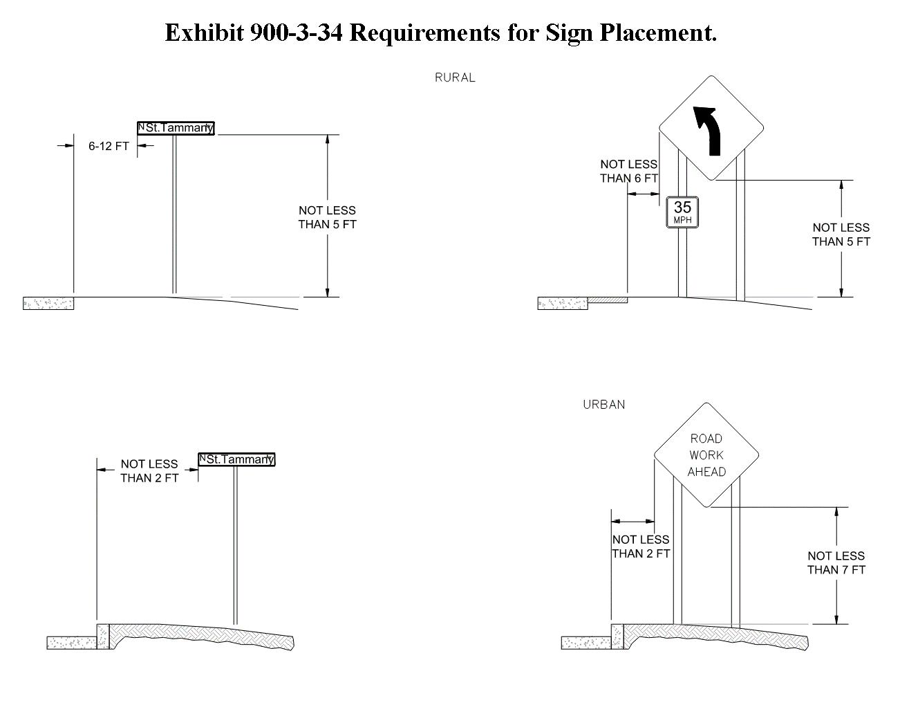
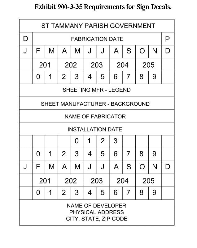
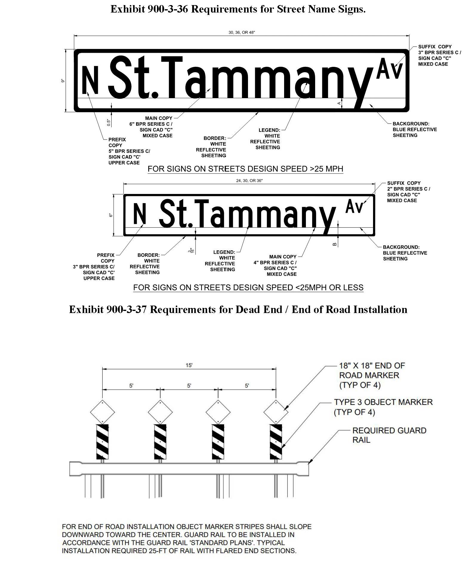
E.
Specialty Street Name Signs, Traffic Control Signs and Mounting Poles.
1.
New Subdivisions and Planned Unit Developments (PUDs) applying for Final Subdivision Approval after March 01, 2016.
a.
The applicant for a new Subdivision or PUD who upon completion of the development intends to dedicate the roads to the parish for acceptance into the parish road maintenance system, shall be responsible for installing uniform Street Name and Traffic Control signage, including the associated mounting poles, in accordance with the requirements of this code.
i.
A signage plan must be produced as part of the final plat and construction plan review and approval and must be approved by the Department of Engineering.
ii.
The signage plan shall include the GPS location of each Street Name and Traffic Control sign in the subdivision.
iii.
The applicant must certify that the Street Name signs, Traffic Control signs, and associated mounting poles comply with the most current MUTCD and AASHTO guidelines, as well as the requirements of this code, before being accepted into the parish road maintenance system.
b.
For Subdivisions and PUDs whose roads will be dedicated to the parish for acceptance into the parish road maintenance system upon completion of the subdivision, but whose Street Name signs, Traffic Control signs, and associated mounting poles will be privately maintained by the developer, or homeowners' association, or other stated owner. A signage plan must also be produced as part of the final plat and construction plan review and approval reviews and must be approved by the Department of Engineering, but specialty mounting poles and sign borders are permitted as long as they meet the installation, crashworthiness and breakaway requirements set forth in the most current AASHTO and MUTCD guidelines as certified by the applicant. The signage plan shall include the GPS location of each Street Name sign or Traffic Control sign in the subdivision.
i.
Any variance from the provisions of these regulations regarding sign size, mounting height or mounting placement must be approved by the Department of Engineering and will be granted only in the event that engineering judgment determines that a variance is warranted.
ii.
A specialty mounting pole is defined as any Street Name sign or Traffic Control sign mounting pole other than the U-channel Standard pole described in this code above.
iii.
The material specification for the blades of the signs must comply with the material specifications of this code, and any framing of the blade cannot alter the sign shape, minimum size, or color, or in any way obscure the blade of the sign, including its border. Privately maintained Street Name signs must also conform to one of the color schemes listed in this code.
iv.
In the event that any development elects to install and maintain more decorative signage, the responsibility for the ongoing maintenance must be clearly indicated on the final plats for that development.
v.
All standards set forth in the most current MUTCD and AASHTO Roadside Design Guide must be met per federal law.
vi.
The applicant, as part of the final plat approval, shall certify that all specialty mounting poles and their attendant Street Name or Traffic Control signs will be installed and maintained in perpetuity at the applicant's or homeowners' association's (or other stated owner's) expense. However, the parish maintains the right to immediately replace any and all damaged or missing Street Name signs, Traffic Control signs, and specialty mounting poles with standard parish signs and mounting poles described within this code if the applicant or homeowners' association (or other stated owner) fails to repair or replace said Street Name sign, Traffic Control sign, and/or mounting pole and the parish receives notification of the deficient condition. Furthermore, the parish reserves the right to replace any privately maintained Street Name sign, Traffic Control sign, and mounting pole which poses any safety risk with standard Parish signs described within this code. Under no circumstances will the parish be responsible for installing, maintaining, or repairing specialty mounting poles. The parish installed signs and mounting poles shall remain until replaced and returned to the parish by the applicant or homeowners association (or other stated owner).
2.
Subdivisions and Planned Unit Developments (PUDs) having received Final Subdivision Approval prior to March 01, 2016.
a.
The provisions of these regulations shall not apply to Subdivisions, PUDs, and TNDs with privately maintained Street Name signs and Traffic Control signs which have received final subdivision approval prior to March 01, 2016. However, if the developer, homeowners' association, or other stated owner of an existing subdivision plans to replace all Street Name signs, Traffic Control signs, and attendant mounting poles within the subdivision, a signage plan shall be submittal to the parish by a professional engineer, and shall comply with the provisions of this code.
b.
If any development exempt under this section requests that the parish assume maintenance of signage, it must first bring all existing signage up to the new standards described herein.
c.
For subdivisions that will privately maintain Street Name signs and Traffic Control signs, the developer shall include on the final subdivision plats an affirmative declaration that the Street Name signs and Traffic Control signs within the subdivision shall be privately maintained by the applicant, homeowners association, or other owner for the subdivision as an affirmative obligation of that person or entity.
Sec. 900-6.1 - Generally.
A.
Purpose. The purpose of the drainage and flood prevention regulations is to ensure the general health, safety, and welfare of the citizens of St. Tammany Parish. These provisions apply to all land and improvements within the unincorporated limits of St. Tammany Parish unless expressly exempted herein or by any other applicable law. The provisions for water management are incorporated herein and shall be applicable to the modification of existing drainage, placement of any fill material, and/or construction on any lot or parcel of property, in whole or in part.
1.
Managing the movement of water across and within a development site involves a series of considerations including how flood prone the site is, how suited the site is to handle stormwater runoff internally, and how activities that create runoff on the site may affect the health of nearby waterbodies. This section addresses these considerations consecutively in support of more comprehensive site development approaches that can support both flood risk reduction and natural resource preservation.
2.
This section includes requirements for properties located within FEMA-identified Special Flood Hazard Areas with the intent mitigate the impacts of flooding by regulating development practices in these flood hazard areas.
3.
This section also outlines standards which promote low impact development in Sec. 900-6.8 which is a stormwater management strategy to maintain and restore the natural hydrologic character of a development site and prevent increases in downstream flooding by reducing site runoff, such as through the promotion of more sustainable, on-site stormwater management practices.
4.
Water Quality aims to prevent pollution and mitigate adverse impacts to the health of nearby waterbodies, such as through standards for pre-construction site activities.
Sec. 900-6.2 - Drainage system requirements.
A.
General. A drainage system shall be provided and designed in accordance with the best modern engineering practices so as to adequately contain and carry off, to the point of ultimate disposal, such runoff as can be expected in the area, taking into consideration the number and type of buildings or structures to be erected and certifying that the runoff will not be increased by the proposed development.
1.
Permanent benchmarks shall be installed by the applicant at convenient locations as approved by the Department of Engineering in each subdivision or phase before As Built Plan approval is granted. The location and elevation of each benchmark shall be clearly noted on the plat of the subdivision filed for record with the clerk of court. Whenever practical, the elevation of the benchmark shall accurately be related to mean sea level as established by the U.S. Coast and Geodetic Survey, the U.S. Army Corps of Engineers, or the LADOTD.
2.
The elevation of the center of the completed streets shall also be noted on the as-built paving and drainage plan at intervals not to exceed 500 feet and at all intersecting roadways, and said elevations are to be established from the benchmark after completion.
B.
Direction of Flow of Surface Water for Individual Lots or Parcels. Applicants shall indicate on the "as-built" paving and drainage plan the direction of flow of surface water for individual lots or parcels, where:
1.
Surface drainage must be designed to flow toward the roadway or to a ditch which is adjacent to the lot or parcel, and the ditch must be located within a parish servitude when it is a public access subdivision or within a private servitude when it is a private subdivision.
C.
As Built Plans.
1.
As-built paving and drainage plans must indicate the invert elevation of the roadside ditch at each property line.
2.
Any subdivision to be approved following adoption of the ordinance from which this subsection is derived shall be subject to the following procedures and requirements:
3.
The final proposed subdivision plat and construction plan shall accurately depict the location of any open drainage ditch, channel, canal, or similar drainage feature, and any natural river or stream that is situated within the boundaries of the proposed subdivision.
4.
Except as provided for "Boat houses and boat slips," no part of a permanent structure, including a driveway and/or fence, shall be located within 20 feet of the top of bank of an open drainage ditch, channel, canal, or similar drainage feature, including a natural river or stream, unless subsurface drainage is installed. This requirement is not applicable to dry or wet retention ponds.
5.
The Department of Engineering shall determine, based upon the data and information that is to be contained in the subdivision plan submitted and the construction documents, whether subsurface drainage is required. The determination is to be made based on considerations of the size of the parcel or lot; available building site (including driveway) on the parcel or lot in relation to the location of the open drainage ditch, channel, canal, or similar drainage feature; any restrictions on the size of the structure; and any other pertinent information or data deemed necessary by the Department of Engineering to ensure that no permanent structure, including a driveway and/or fence, is to be located within 20 feet of an open drainage ditch, channel, canal, or similar drainage feature. This requirement is not applicable to dry or wet retention ponds.
6.
A building permit shall not be issued for the construction of any permanent structure, including a driveway and/or fence, where any part of said structure would be located within twenty (20) feet of an open drainage ditch, channel, canal, or similar drainage feature. This requirement is not applicable to dry or wet retention ponds.
7.
Subsurface drainage will be required on all newly created roadside ditches, that exceed a depth of 3 feet as measured from the centerline of ditch to the crown of the adjacent road.
8.
The requirements of subsurface drainage may be modified when plans are approved by the Department of Engineering.
Sec. 900-6.3 - Hydrologic and hydraulic analysis and paving and drainage plan.
A.
General. The purpose and intent of this section is to require a drainage and paving plan to be stamped and certified by a licensed professional engineer registered in the State of Louisiana for construction of commercial, industrial, institutional, and certain multifamily developments, with the goal of improving pre-development runoff and reducing post-development runoff based on a minimum 25-year storm event.
B.
Applicability. All commercial, industrial, institutional and multifamily development for townhouses, apartments, condominiums and nursing home uses that require a building permit or site work permit shall submit a drainage and paving plan with the permit application. Said plan shall be forwarded to the Department of Engineering for review and approval before the issuance of a building permit.
C.
Responsibility. It shall be the responsibility of the applicant to create a site development plan that will complement the drainage and paving plan utilizing site design criteria to result in the reduction of runoff from post-development.
D.
Criteria. The drainage and paving plan shall be stamped and certified by a licensed professional engineer registered in the State of Louisiana and shall meet the following criteria:
1.
Parcels 0 to 2 acres in size shall be required to reduce pre-development peak runoff by at least ten percent for a 25-year storm event on-site.
2.
Parcels 2 to 5 acres in size shall be required to reduce pre-development peak water runoff by at least 15 percent for a 25-year storm event on-site.
3.
Parcels 5 acres and larger shall meet all drainage requirements for subdivisions, including a reduction of pre-development peak runoff by at least 25 percent for a 100-year storm event on-site.
4.
Whenever a parcel that is greater than 5 acres is proposed to be developed in phases, or subdivided through the minor subdivision process, where any proposed phase or lot is less than five acres, such development shall meet the requirements of 900-6 of this section. The drainage and paving plan must address drainage in terms of the development of the entire parcel, not just the phase currently being proposed to be developed, taking into consideration all of the regulations of the zoning district designation of the property that could be pertinent to drainage, including maximum net density permitted, minimum area regulations, maximum lot coverage, and off-street parking and loading requirements.
5.
A combination of detention methods may be utilized to meet the criteria as established in this section. Off-site detention facilities may be utilized if approved by the Department of Engineering.
6.
If the parking area is proposed to be utilized as a detention area, the maximum planned storage shall not exceed a depth of 6 inches at any inlet or the lowest point of storage.
E.
Documents Required. Documents required for drainage and paving plan review. In order to expedite the drainage plan review for all commercial, industrial, institutional and multifamily developments for townhouses, apartments, condominiums and nursing home uses, the Department of Engineering shall require at a minimum the following documents be provided:
1.
A vicinity map indicating the location of the proposed project.
2.
A pre-development drainage plan (existing conditions).
3.
Identify fill area(s) and associated fill depth(s).
4.
A post development paving and drainage plan and an as built paving and drainage plan.
5.
If building has downspouts, an architect's drawing is required.
6.
If the outfall needs to discharge to the ditch or pond, the invert elevations of associated culvert(s) and bottom elevation of accepted ditch or pond shall be provided.
7.
If driveway culvert needs to be installed at the state highway ditch, an approval sheet from the state shall be provided prior to the parish approval.
8.
Hydrological Analysis as provided for below.
F.
Hydrological Analysis. A hydrological analysis of both pre-development and post-development runoff shall be provided. The applicant shall also provide a water surface profile for 100-year, 50-year, 25-year and 10-year storm events.
1.
The hydrological analysis shall meet all applicable parish ordinances and the following requirements:
a.
The applicant shall also study the effect of any proposed development on existing downstream drainage facilities outside the area of development. Local drainage studies, together with any other appropriate study, shall serve as a guide to needed improvements as determined by the Department of Engineering.
b.
No development may be constructed or maintained so that surface waters from such development are collected and channeled downstream at such locations or at such volumes or velocities as to cause degradation, alteration or damage to lower adjacent properties.
c.
Where it is anticipated that the additional runoff incident to the development will increase the water surface profile downstream, the parish shall withhold approval of the development until provisions have been made for the detention of stormwater and resolution of such conditions in conformance with these requirements and the department of engineering. No development shall be approved unless the necessary drainage will be provided to a drainage watercourse or facility that is adequate to receive the proposed drainage without adverse impact on downstream properties.
d.
No development may be constructed or maintained where such development would impede the flow of water from upstream properties across the property proposed to be developed. All drainage rights-of-way and culverts or other drainage facilities shall be large enough to accommodate runoff from the property proposed to be developed as well as upstream flow originating outside of the proposed development. All existing watercourses passing through the property of the proposed development shall be maintained to accommodate up to the 100-year storm events. Any proposed alteration or relocation of an existing watercourse or drainage facility may only be approved when the Department of Engineering has determined that any such proposal meets all applicable parish drainage requirements. The applicant determine the necessary size of the drainage facilities, assuming conditions of maximum potential watershed development permitted by these regulations.
e.
If the site is located in a critical drainage area or area of special concern, a drainage basin study can be required to demonstrate if there will be adverse drainage impacts on surrounding properties.
f.
The Department of Engineering reserves the right to hold the certificate of occupancy in order to allow for a final inspection.
g.
In the event of a conflict between any provision within this section, or between a provision in this section and any other drainage or flood control ordinance, the more stringent provision shall be applicable.
h.
All the above drawings and hydrological analysis shall be prepared and signed and sealed by licensed professional engineer registered in the State of Louisiana.
7.
Design and Analysis Criteria. The following are recommended methods for analyzing the impacts of designed stormwater control measures (SCMs). The design of engineered facilities requires professional judgement and proper function of these facilities is the responsibility of the designer.
a.
Allowable Methods—Hydrologic Analysis. The applicant may utilize the Rational Method, the Modified Rational Method, and the NRCS (SCS) Method for Hydrologic analyses subject to the following limitations:
Exhibit 900-6-1 Hydraulic Analysis Allowable Methods.
b.
Rational Method. For developments of 20 acres or less, the rational method (as prescribed within Chapter 3 - Part C of the Louisiana Department of Transportation and Development Hydraulics Manual, 2011 Edition) shall be used for determination of peak runoff and for the design of open channel and storm sewer systems. Computation of Time of Concentration (Tc) shall be computed as prescribed by the DOTD Hydraulics Manual or via TR-55.
c.
Modified Rational Method. Retention facilities for developments less than 1 acres in size may be designed utilizing hydrographs developed by the modified rational method. Modified Rational Method recognizes that the duration of a storm can and will sometimes be longer than the time of concentration. This longer duration storm, even though it produces a lower peak Q, can produce a larger volume of runoff than the storm duration equal to the actual time of concentration of the drainage area. In order to ensure the proper design of stormwater management basins, the volume of runoff for the critical storm duration should be calculated. Hydrographs shall be calculated for at least the following durations: (1.0 x Tc, 1.5 x Tc, 2 x Tc, and 3tc, or until reservoir routing calculations identify the critical storm duration. Retention ponds shall be sized such that the peak outflow from the retention facility at the critical storm duration complies with the hydraulic and hydrologic performance requirements of this code. Results developed by the modified rational method shall be confirmed by reservoir routing.
d.
NRCS (SCS) Method and Unit Hydrograph. For developments greater than 20 acres in size, the NRCS Method (as prescribed in Chapter 3 - Part B of the Louisiana Department of Transportation and Development Hydraulics Manual, 2011 Edition) shall be used for the determination of peak runoff and for the development of hydrographs for reservoir routing for developments. Where the NRCS method is used to develop hydrographs, a shape number of 256 shall be utilized. Hydrographs shall be developed using a Type III, 24 Hour Rainfall Distribution shown in the Technical Publications of the National Weather Service of the National Oceanic and Atmospheric Administration. Additionally, when using the NRCS method, modifications for ponding shall be made as provided for below:
i.
Modification for Ponding Areas. Where a drainage area contains ponding areas or swampy areas, the peak runoff shall be adjusted as provided for in the equation below. The tables below indicate the appropriate adjustment factors to be utilized.
![]()
Exhibit 900-6-2 Modification for Ponding Areas at Design Point.
Exhibit 900-6-3 Modification for Ponding Areas Throughout Watershed.
Exhibit 900-6-4 Modification for Ponding Areas in Upper Watershed.
e.
Allowable Factors for C and Curve Number. Allowable values for the runoff coefficient, "C" and Curve Numbers "CN" are as shown in the tables below. Hydrologic soil group shall be determined by a licensed geotechnical engineer or the United Soil Conservation Service Classification Maps.
Exhibit 900-6-5 Allowable Curve Numbers.
Exhibit 900-6-6 Allowable Runoff Coefficients.
f.
Other Methods. Where acceptable to the Departments of Planning and Engineering, alternate methods may be utilized for the analysis and design of drainage facilities. Where proposed, the applicant shall submit all clarification and documentation to the satisfaction of the Department and Engineering.
g.
Tailwater Conditions. Where available, the applicant shall utilize Flood Insurance Studies (FIS) promulgated by the Federal Emergency Management Agency (FEMA) or any available data/studies that would demonstrate best available data for determining these conditions for the determination of tailwater conditions at discharge.
8.
Open Channel (Ditch) Analysis and Design. Open channels shall be analyzed and designed as prescribed in Chapter 4 of the Louisiana Department of Transportation and Development Hydraulics Manual, 2011 Edition.
9.
Culvert Drainage Design. Culverts shall be analyzed and designed as prescribed in Chapter 5 and 6 of the Louisiana Department of Transportation and Development Hydraulics Manual, 2011 Edition. Culverts shall be designed such that they meet the Urban case of Table 6.9-1 of the Louisiana Department of Transportation and Development Hydraulics Manual, 2011 Edition
10.
Storm Drain System Analysis and Design. Storm drain systems shall be analyzed and designed as prescribed in Chapter 8 of the Louisiana Department of Transportation and Development Hydraulics Manual, 2011 Edition. Storm drain systems shall be designed such that they will convey the peak runoff generated by the 25-year storm.
a.
Curb, Gutter, Grates and Inlets. Curb, gutter, grates and inlets shall be analyzed and designed as prescribed in Chapter 8 - Part A of the of the Louisiana Department of Transportation and Development Hydraulics Manual, 2011 Edition. Inlets shall be designed such that one half of the outer travel lane remains free of inundation during the 10-year storm event.
b.
Storm Water Drainage Pumping Stations. Stormwater drainage pumping stations shall be analyzed and designed in accordance with Chapter 10 of the Louisiana Department of Transportation and Development Hydraulics Manual, 2011 Edition, Water Environment Federation Manual of Practice FD-4 and the applicable standards of the Hydraulics Institute (HI). Electrically powered drainage pumping station shall be provided generator capacity sufficient to run 100 percent of the capacity of the drainage pumping station for a minimum of 72 hours continuously without refueling.
11.
Detention Design. Detention design may be part of the Stormwater Management Plan (SMP) and shall include detention ponds and metering structures. Linear detention within roadside ditches is not acceptable and shall not be included as storage areas within any SMP.
a.
Dry Basins. Dry basins shall be designed such that the primary outlet devices restrict the flow and allow water to pond in a safe contained fashion. A properly designed emergency spillway shall be provided capable of passing the 100-year storm if the drainage area is greater than 25 acres. Side slopes shall be no steeper than 3:1 but if vegetative groundcover is to be used, flatter slopes are recommended. The basin shall be constructed to insure positive drainage with a concrete low flow swale.
b.
Wet Basins. Wet basins shall be designed such that the primary outlet devices restrict the flow and allow water to pond in a safe contained fashion. A properly designed emergency spillway shall be provided capable of passing the 100-year storm if the drainage area is greater than 25 acres. Side slopes shall be no steeper than 3:1 above the normal water surface elevation. If vegetative groundcover is to be used, flatter slopes are highly recommended. A minimum of 60" of standing water shall be maintained in all wet ponds, and that volume of the water permanently retained within the wet pond shall be excluded from the retention volume in reservoir routing computations.
c.
Pipe and Channel Storage. Linear detention within roadside ditches and storm drain pipe shall not be included as storage areas.
d.
Outlet Devices. Outlet devices may include weirs, orifices, and culvert controls. Outlet devices shall be modeled and analyzed using equations suitable for each application and subject to the approval of the Department of Engineering.
12.
Basin Routing Methodology. Impoundments shall be sized using the Storage indication Routing method (as prescribed in Ponce, V. M. 1989. Engineering Hydrology, Principles and Practices. Prentice Hall, pages 260-261) and hydrographs.
13.
On site detention requirements may be waived or modified based on hydrological analysis of existing conditions, location of the development within the drainage basin and analysis assuring no negative effect within the basin of the waiver. A waiver is expressly prohibited for developments located within the upper one- third of the drainage basin, unless the runoff resulting from the development can be routed to a regional detention facility. After technical review, the department of engineering shall accept or reject the proposed waiver. The waiver will be presented to the Department of Engineering for final plat and construction plan approval.
14.
If a waiver is accepted pursuant to the previous subsection, in lieu of on-site detention, the applicant shall be assessed a drainage fee. This fee shall be payable to the parish or designated drainage district for the sole purpose of making improvements to the affected drainage basin. The fee shall be due prior to the issuance of any work orders by the parish.
The drainage fee shall be per acre, as follows:
*The fee shall be used solely for planning, studying, acquisition and/or construction of regional detention facilities and/or drainage system improvements within the affected basin.
15.
All retention reservoirs and associated drainage structures shall be designed to provide for reductions in peak rate of runoff for all storm events up to the 100-year storm. The peak rate of runoff for the 25-, 50- and 100-year storm shall be reduced by 25 percent. At no time shall the peak rate of runoff exceed that of the pre-development conditions of the subject parcel. Calculations shall be provided for the 25-, 50- and 100-year storm events that display the effects of a two and 24-hour duration.
G.
Drainage Rights-of-way. Drainage ditches, channels, canals, and similar drainage features shall be located within a dedicated right-of-way and not located within an individual lot(s). Dedicated right-of-way may be located in greenspace or open space.
1.
If direct access is not available, there shall be a dedicated right-of-way access that extends to a public or private road that is a minimum of 25 feet wide.
2.
A drainage ditch, channel, canal, or similar drainage feature right-of-way shall comply with the following criteria:
a.
Provide a minimum of 15 foot wide working distance on one side of the ditch, channel, canal, or similar drainage feature and a 5 foot wide distance on the opposite side of the ditch. Measurements for this subpart shall be taken from top of bank to boundary line of right-of-way.
b.
The dimensions of the ditch, channel, canal, or similar drainage feature shall be determined by hydrologic calculations in accordance with criteria stated herein.
c.
Side slopes shall be designed at a 3:1 ratio (three feet horizontal to one foot vertical). When a 3:1 design cannot be achieved, the proposed drainage ditch, channel, canal, or similar drainage feature shall be subsurface.
3.
Drainage plans shall include cross-section(s) for each drainage ditch, channel, canal, or similar drainage feature clearly showing conformance to this section.
a.
Alternate. All subsurface drainage shall be located within a dedicated right-of-way and shall not be located within the boundaries of an individual lot(s). Dedicated right-of-way may be located in greenspace or open space; except for subsurface drainage installed on and serving a single lot or within a shared swale between two lots.
4.
If direct access is not available, there shall be indicated on the final plat and construction plan a dedicated access that is not located within an individual lot and that extends to a public or private road that is a minimum of 25 feet wide. Dedicated access may be located in greenspace or open space.
5.
All subsurface drainage rights-of-way shall be designed in accordance with all of the following criteria:
a.
Provide a minimum 20 foot wide right-of-way distance. Right-of-way shall be increased as required to allow for a minimum of 5 feet from edge of pipe to right-of-way boundary at all locations. Additional right-of-way width may be required at the discretion of the Department of Engineering.
b.
This right-of-way shall be exclusively for drainage, except when necessary for crossing by other utilities.
c.
The subsurface drainage shall be sized for the capacity determined by hydrologic calculations in accordance with criteria stated within this code.
6.
Drainage rights-of-way that have not been dedicated to the Parish and remain in private ownership shall be subject to the following procedures:
a.
Inspection. The Department of Engineering, Department of Inspections, or Code Enforcement, or their representatives, shall be permitted to access drainage rights-of-way in private developments to determine compliance with the provisions of this Chapter.
b.
Enforcement. Violations will be processed by the Code Enforcement, Department of Engineering or permit inspections personnel using standard code violation protocol.
c.
Administration. This section shall be administered by the parish Department of Engineering with the assistance of any other parish personnel or agency that are deemed necessary by the parish and/or its regulations.
H.
Design and Location of Drainage Structures. All lots and blocks created or reconstructed must meet the minimum lot and block size and dimension standards of this section and the zoning district in which the site is located. If requirements conflict, the more restrictive shall apply.
(Ord. No. 25-5685, 3-6-2025)
Sec. 900-6.4 - Retention ponds.
A.
Retention/Detention Ponds. Retention/Detention Ponds shall comply with the following requirements:
1.
Requirements for both wet and dry ponds:
a.
Side slopes shall have a slopes must have a minimum 3H:1V slope.
b.
Minimum access servitude width from pond to parish road must be twenty-five (25) feet.
c.
Clear buffer around the periphery of pond must be twenty (20) feet; ten feet must be on a flat surface and not a pond side slope.
d.
The applicant must furnish a copy of the title to the land.
e.
When applicable, an "act of dedication" with a legal description of the property to be dedicated to the parish must be furnished.
f.
Ponds being utilized for detention/retention shall have an appropriate designed and constructed overflow structure to handle storm situations exceeding the 100-year storm event. The overflow structure shall be designed to overfall to an appropriate drainage feature or servitude.
2.
Requirements specific to wet ponds:
a.
A minimum low stage depth of at least 5 feet.
3.
Requirements specific to dry ponds:
a.
Exit structure invert elevation must be 0.5 feet lower than the lowest elevation of the pond bottom.
b.
A narrow low stage ditch shall be constructed through the pond to the exit structure invert elevation.
B.
Acceptance into the Parish System. The following procedures are hereby established for acceptance of retention/detention ponds, existing as of the date of the ordinance from which this article is derived, into the parish maintenance system:
1.
The owner submits a petition requesting that the pond be taken into the Parish maintenance system. The petition must include copy of title and a survey.
2.
The petition will be reviewed by the Department of Engineering and Department of Public Works to determine what is needed before the pond can be considered for acceptance.
3.
The following requirements are hereby established for retention/detention ponds, constructed after the adoption of the ordinance from which this article is derived. Compliance with all standards as set forth below must be verified by department of engineering prior to acceptance.
4.
The petitioner will be advised of what is needed for acceptance and will be advised that acceptance by the parish is for maintenance purposes only and not for aesthetic purposes.
C.
Maintenance of privately owned retention/detention ponds in major subdivisions and commercial developments.
1.
Maintenance. Retention and/or detention ponds in major subdivisions and commercial developments requiring the approval of a commercial permit and drainage plan which have not been dedicated to the parish and remain in private ownership, or owned by other public entities, shall be maintained at all times in accordance with the requirements of any approved drainage plan(s) for the private subdivision or commercial development, or in the absence thereof, the applicable standards in this chapter.
2.
Inspection. The Department of Engineering, Department of Inspections, or Code Enforcement, or their representatives, shall be have the right to inspect privately owned retention/detention ponds to determine compliance with the provisions of this Chapter.
3.
Enforcement. Violations will be processed by the code enforcement, department of engineering or permit inspections personnel using standard code violation protocol.
4.
Administration. This section shall be administered by the parish Department of Engineering with the assistance of any other parish personnel or agency that are deemed necessary by the parish and/or its regulations.
(Ord. No. 25-5685, 3-6-2025)
Sec. 900-6.5 - Placement of fill.
A.
Generally.
1.
Adverse drainage impact. It shall be prohibited to place fill or construct improvements on any parcel of property so as to cause adverse drainage impacts on any adjacent parcel.
2.
Net fill prohibited.
a.
Net fill means the placement of any fill material that results in any increase in the surface elevation of property or adjacent property from its natural or pre-development state.
b.
Net fill shall be strictly prohibited in any critical drainage area and on any lot or parcel 90 feet or less in width, except with an approved development plan or with the express written consent of the engineering department. Any request to place fill in a critical drainage area or a lot or parcel 90 feet or less in width shall be in accordance with the procedures and guidelines outlined herein.
c.
A lot or parcel of property shall be deemed to be located in a critical drainage area when any part thereof is located within a critical drainage area. Net fill shall not be placed on any part of such property, except with an approved development plan or with the express written consent of the department of engineering.
3.
Fill materials prohibited within 200 feet of drainage waterway.
a.
The Parish Council provides for the requirement that any development, including a residence located within 200 feet from the middle of a drainage waterway in Ward 8, excluding Parish Council District 6, as further specified must utilize pilings, piers or other similar methods to elevate the structure to the appropriate base flood elevation height as determined by FEMA instead of the use of fill. No fill should be allowed within 200 feet which is not a part of the building envelope or driveway.
b.
Fill not to exceed an average of 18 inches may be allowed to level the building envelope.
c.
Piers or similar methods allowing the sheet flow of water under the structure should be utilized to meet the required flood zone elevation. The specified drainageways are as follows:
i.
W-15 Canal.
ii.
Gum Bayou.
iii.
W-14 Canal.
iv.
Reine Canal.
v.
Eddines Canal.
vi.
Poor Boy Canal.
vii.
Exemptions areas or projects from the above specified drainageways.
(A)
Excluding 1,000 feet on the north side of 1,000 feet on the south side of Gause Boulevard - W-15 Canal.
(B)
Excluding the FEMA Hazard Mitigation Grant Program, Daney Street Project, W-14 Canal.
(C)
Any other authorized parish drainage project.
d.
Waiver provision. The department of engineering may waive the requirements of this chapter for a project of development, when the waiver is based on a drainage plan prepared by a licensed engineer, specific location of the project and the existing development patterns in the area or minor elevation differences between the natural ground and base flood elevation. This waiver should be based upon the report indicating that the fill will not produce a significant impact in comparison to meeting the intent of this chapter. The engineering department does have the authority not to issue a waiver regardless of the independent study which indicates that there may not be significant impact.
4.
General residential fill standards. The placement of fill material on any lot or parcel located within any critical drainage area shall be permitted only after a development plan has been submitted and approved by the department of engineering. In the event that the department of engineering determines that fill work is permitted on the particular parcel, the fill work must comply with the following specific standards:
a.
In some cases, subject to the discretion of the department of engineering, excavation of existing soil and its replacement with fill is permissible at the site provided it can be demonstrated to have no increase in the natural ground elevation and no net impact on the function of the critical drainage area.
b.
Fill shall be limited to the roof-shed area of the proposed primary structure and access to the site and shall not exceed that which is necessary to prepare an adequate building footprint.
c.
Site improvements (roads, structures, fill, etc.) shall not impede natural drainage pathways or parish road or drainage easements, servitudes, or rights-of-way.
d.
Fill for driveways must not exceed six inches above natural ground elevation except where fill is part of the foundation for the main residence, carport, or garage. Fill may also be placed to soften the transition between elevations to a slope not less than four horizontal feet to every one vertical foot.
e.
Fill may be authorized by the department of engineering in those cases where, due to the size and location of the parcel of property, on-site or off-site mitigation can be provided and the department of engineering also determines that there will be no loss of flood plain storage, no loss of stream flow capacity and the applicant demonstrates that no adverse impacts will occur to adjacent properties, to other properties within the subject watershed, and to the function of the critical drainage area.
f.
Storage capacity required for drainage or retention as listed in Section 900-6.2, Drainage System Requirements, Section 900-6.3, Hydrologic and Hydraulic Analysis and Paving and Drainage Plan, or Section 900-6.4, Retention Ponds, shall not be utilized to meet the fill mitigation required in this section.
5.
General Nonresidential standards. Any paving, grading, excavation, or placement of fill on commercial, industrial, institutional or multifamily development sites must obtain an approved development plan in the form of a properly issued building permit, site work permit or subdivision work order prior to the commencement of work. In cases of commercial, industrial, or institutional development on any lot or parcel of property that has any part thereof located within a critical drainage area, the placement of fill on such lot or parcel may be permitted, in the discretion of the department of engineering, provided that:
a.
Soil material in a volume equal to the fill material proposed to be placed on the property is excavated and removed from the property, such that the flood storage capacity of the property is maintained for a 100-year frequency flood event;
b.
Off-site mitigation will be provided, and the engineering department also determines that there will be no loss of floodplain storage and no loss of stream flow capacity. It is expressly prohibited to utilize off-site mitigation within the boundaries of the now dissolved Gravity Drainage District No. 5 using the boundary description found in section 115-259;
c.
The applicant can demonstrate that no adverse impacts will occur to adjacent properties, to other properties within the subject watershed, and to the function of the critical drainage area;
d.
The proposed development complies with all other applicable drainage regulations; and
e.
Storage capacity required for drainage or retention as listed in Section 900-6.2, Drainage System Requirements, Section 900-6.3, Hydrologic and Hydraulic Analysis and Paving and Drainage Plan, or Section 900-6.4, Retention Ponds, shall not be utilized to meet the fill mitigation required in this section.
6.
Subsurface drainage. It shall be unlawful for any owner, contractor, builder or subdivider to use, employ or apply fill in and/or on any lot situated within a subdivision located in the unincorporated limits of the parish wherein subsurface drainage is installed unless this material is contained within the perimeter of the lot in an adequate manner to prevent run-off of the sand, fill, clay or mixture thereof onto sidewalks, streets or into culverts or onto the property of abutting property owners.
7.
Relocation of open drainage ditches, drainage channels and similar drainage features.
a.
For purposes of this subsection, the term "relocation" means changing the location of all or any part of an open drainage ditch, drainage channel or similar drainage feature that is partially located on, or which traverses, a lot or parcel of property.
b.
The provisions of this subsection shall be applicable to any lot or parcel of property, regardless of the size of the lot or parcel and whether or not it is located in a critical drainage area or area of special concern.
c.
Whenever the owner of any lot or parcel of property proposes to fill in an existing drainage ditch, drainage channel or similar drainage feature that is partially located on, or which traverses, the owner's property in order to relocate the ditch, drainage channel or similar drainage feature to another location on the property, in addition to complying with all other applicable provisions of this section, the owner shall provide a plan for the proposed relocation, supported by a complete hydrologic report taking into consideration impacts of upstream and downstream properties, that is prepared by a licensed civil engineer. The department of engineering shall conduct a site visit prior to approval of the proposed plan. The proposed relocation plan may be included in the "Existing and Proposed Grade Elevation Form," provided it is prepared by a licensed civil engineer.
d.
If the proposed relocation results in all or any part of the relocated drainage ditch, drainage channel or similar drainage feature being within 20 feet of the foundation of an existing or proposed structure, the relocation of the drainage ditch, drainage channel or similar drainage feature must be accomplished by subsurface installation. If no part of the drainage ditch, drainage channel or similar drainage feature is to be within 20 feet of the foundation of an existing or proposed structure, the department of engineering shall determine, considering best engineering practices and the issue of maintenance of drainage, whether subsurface installation is required for all or any part of the relocated drainage ditch, drainage channel or similar drainage feature.
e.
The requirement of subsurface installation for a relocated drainage ditch, drainage channel or similar drainage feature may be waived by the department of engineering provided that:
i.
The property owner, and licensed civil engineer engaged by the owner, have independently determined that the relocated drainage ditch, drainage channel or similar drainage feature, if relocated without subsurface drainage, will not undermine the foundation or otherwise cause any damage to the property or structure; and
ii.
The department of engineering determines that the relocation will not impede drainage or interfere with the proper maintenance thereof. It is expressly prohibited to grant a waiver under this subsection within the boundaries of the now dissolved Gravity Drainage District No. 5.
iii.
The hereinabove provisions of this subsection shall not be construed as being applicable to any roadside ditch or to any property that is publicly owned and maintained by the parish or any political subdivision thereof.
B.
Critical Drainage Areas.
1.
Description. Critical drainage areas are areas determined by the parish department of engineering, after careful consideration of the available data, to be of critical importance for its role in the conveyance, moderation or storage of stormwater.
2.
List of Areas. Areas within this designation include, but are not limited to, the following:
a.
Areas anticipated to be inundated by a 100-year storm event, including areas adjacent to streams, upland areas, and areas of isolated or permanent flooding.
b.
Areas of concentrated storm water flow, including but not limited to concentrated sheet flow, channelized flow, and natural hydrologic features or channels of all types and sizes.
c.
Any area designated by FEMA as Flood Hazard Area A, V, or the equivalent, indicating inundation during a 100-year event.
d.
Areas included within wetlands as defined by the 1987 U.S. Army Corps of Engineers Wetland Delineation Manual.
e.
Those areas that are designated as a critical drainage area on the most current critical drainage area map that is on file in the office of the parish department of engineering.
3.
Map. The critical drainage area map is the official critical drainage area map generated and maintained by the department of engineering. The map will be periodically revised, based on information and data available at the time, in an effort to provide reasonably updated information to the public regarding the areas of the parish considered to be critical drainage areas.
C.
Areas of Special Concern.
1.
A certain portion of Tammany Hills and Alexiusville Subdivisions, Ward 3, District 5, located inside the boundaries described immediately below, to wit: Beginning at the northeast corner of 9th Avenue and Falconer Drive, proceed in a northerly direction along the eastern edge of Falconer Drive to its intersection with Harrison Avenue, then proceed in an easterly direction along Harrison Avenue to its intersection with 11th Street, then proceed in a southerly direction along 11th Street to its intersection with Madison Avenue, then proceed in a westerly direction along Madison Avenue to its intersection with 5th Street, then northerly along the 5th Street right-of-way to its intersection with Quincy Avenue, then westerly along Quincy Avenue to its intersection with K Street, then south on K Street to its intersection with 9th Avenue, then proceed west on 9th Avenue to its intersection with Falconer Drive and the point of beginning; less and except the western half of Square 15, Tammany Hills Subdivision (eastern side of 5th Street between Adams and Jefferson Avenues), the eastern portion of Square 15, and Square 16.
Beginning at the northeast corner of 9th Avenue and Falconer Drive, proceed in a northerly direction along the eastern edge of Falconer Drive to its intersection with Harrison Avenue, then proceed in an easterly direction along Harrison Avenue to its intersection with 11th Street, then proceed in a southerly direction along 11th Street to its intersection with Madison Avenue, then proceed in a westerly direction along Madison Avenue to its intersection with 5th Street, then northerly along the 5th Street right-of-way to its intersection with Quincy Avenue, then westerly along Quincy Avenue to its intersection with K Street, then south on K Street to its intersection with 9th Avenue, then proceed west on 9th Avenue to its intersection with Falconer Drive and the point of beginning; less and except the western half of Square 15, Tammany Hills Subdivision (eastern side of 5th Street between Adams and Jefferson Avenues).
2.
A certain portion of Cypress Park and Erindale Subdivisions, Ward 7, District 7, located inside the boundaries described immediately below, to wit:
Beginning at the intersection of U.S. Highway 190 and Anchorage Drive, the point of beginning, proceed along the eastern edge of Anchorage Drive in a northerly direction to its intersection with Berry Todd Road, thence proceed along the southern edge of Berry Todd Road in an easterly direction to its intersection with Graci Avenue, thence follow an imaginary line due south from said intersection to the northern most point of Emerald Drive, thence proceed along the western edge of Emerald Drive south to its intersection with U.S. Highway 190, thence proceed along the northern edge of U.S. Highway 190 west northwest to its intersection with Anchorage Drive, the point of beginning.
3.
All that property situated within a re-subdivided portion of Tammany Forest Subdivision, Ward 7, District 7, all as more particularly described immediately below, to wit:
Any and all squares and lots of record within the re-subdivided portion of Tammany Forest Subdivision, located within Section 43, Township 8 South, Range 13 East and as more fully described on the finalized subdivision plat dated August 7, 1985, by NRW and Associates, Inc.
4.
All that property situated within the subdivision known as Dove Park, Ward 4, District 5, Section 26, Township 7 South, Range 11 East, located within the boundaries described immediately below and more particularly depicted on the attached subdivision plat filed for record with the parish clerk of court on June 20, 1957, and identified as Map #16A, to wit:
a.
Any lot or parcel of ground between Sparrow Street and the proposed Judge Tanner Boulevard (formerly the proposed E. Fairway Drive Extension) that abuts or has access to Swallow Street, Egret Street or Partridge Street.
b.
In addition, within the Dove Park Subdivision there shall be a minimum building site of 75 feet front on the setback line.
5.
Any undeveloped lot or parcel of ground situated in the area generally surrounding Eola Street, Jordan Street and Elmer Street, which area is more particularly depicted on the attached aerial and described immediately below, to wit:
a.
A certain piece or portion of ground situated in section 6, Township 8 south, Range 12 east, St. Tammany Parish, Louisiana, and more fully described as follows:
b.
Parcel 1. From the Quarter Section Corner common to section 6, Township 8 south, Range 12 east and section 1, Township 8 south, Range 11 east, go south 89 degrees 51 minutes 30 seconds east a distance of 330.0 feet to a point; said point being the point of beginning.
c.
From the point of beginning proceed north 89 degrees, 18 minutes, 18 seconds east a distance of 1,357.15 feet to a point; thence proceed north 01 degrees, 51 minutes, 49 seconds west a distance of 947.44 feet to a point at the intersection of the western right-of-way of Soult Drive and the southern right-of-way of Highway 1088; thence proceed in a westerly direction along the southern right-of-way line of Highway 1088 a distance of 1,875 feet to a point; thence proceed south 00 degrees, 00 minutes, 00 seconds west a distance of 266.71 feet to a point; thence proceed north 89 degrees, 43 minutes, 43 seconds east a distance of 395.84 feet to a point, said point being the point of beginning.
6.
Any property having, or proposing to have, ingress and egress to and from Lakeview Drive and Carr Drive, Slidell, Louisiana, being more particularly described as follows:
a.
Lakeview Drive: Situated in sections 31, 32 and 33, Township 9 south, Range 14 east, St. Tammany Parish, Louisiana.
b.
Carr Drive: Situated partially in sections 25 and 26, Township 9 south, Range 13 east, and partially in sections 29, 30, 31 and 32, Township 9 south, Range 14 east, St. Tammany Parish, Louisiana.
c.
For these areas listed in f., the amount of fill shall not exceed an elevation of 24 inches above the centerline of the subject road (i.e., Lakeview Drive or Carr Drive).
7.
All property situated in the area generally surrounded by Eleventh Street, Harrison Avenue, Highway 59, Firetower Road, 5th Avenue, and Helenbirg Road, including the Northerly Homes Property subdivision and surrounding area, Ward 3, District 5 and 11, as more particularly described on the attached aerial and described immediately below, to wit, less and except the property situated in Section 12, Township 7 south, Range 11 east, also bearing the municipal address of 21501 Soell Dr.:
a.
Beginning at the southeast corner of Harrison Avenue and 11th Street, proceed in a southerly direction along the eastern right-of-way line of 11th Street for a distance of approximately 5,588 feet to its intersection with the south right-of-way line of Helenbirg Road;
b.
Thence proceed in a southwesterly direction along said right-of-way line for a distance of approximately 3,165 feet to its intersection with the northeast corner of 5th Avenue and Helenbirg Road;
c.
Thence proceed in a easterly direction along the south boundary of said subdivision for a distance of approximately 3,749 feet to a point on the centerline of Firetower Road;
d.
Thence proceed in a southeasterly direction along Firetower Road for a distance of approximately 3,604 feet to its intersection with Hwy 59;
e.
Thence proceed in a northerly direction along Hwy 59 for a distance of approximately 5,543 feet to its intersection with the south right-of-way of Harrison Avenue;
f.
Thence proceed in westerly direction along the south right-of-way line of Harrison Avenue for a distance of approximately 5,390 feet to a point located at the southeast corner Harrison Avenue and 11th Street, said point being the Point of Beginning.
8.
Beginning at the intersection of the eastern Adair Street right-of-way and the northern Florida Street right-of-way, proceed in a southeasterly direction along the northern right-of-way line of Florida Street for a distance of approximately 8,190 feet to the intersection said right-of-way line and the western right-of-way line of Soult Street;
a.
Thence proceed in a northeasterly direction along the Soult Street right-of-way line for a distance of approximately 3,850 feet to a point at the intersection of said right-of-way line and southern right-of-way line of Labarre Street;
b.
Thence proceed in a northwesterly direction along said right-of-way line for a distance of approximately 8,180 feet to a point located at the northwest corner of Square 232 of the Town of Mandeville Subdivision (as delineated on Map #208A);
c.
Thence proceed in a southwesterly direction along the eastern edge of the old Great Northern Railroad line for a distance of approximately 3,855 feet to a point, said point being the Point of Beginning.
d.
This afore-described area of special concern shall be less and except Lot 58a, Square 220A, Town of Mandeville, Section 28, Township 8 South, Range 11 East, Greensburg Land District, St. Tammany Parish, as identified on Map File No. 6373B on file and of record with the Clerk of Court for St. Tammany Parish.
9.
Fill in areas of special concern.
a.
No fill shall be placed on any lot or parcel within the described boundaries of an area of special concern prior to the submission of a development plan to the department of engineering detailing any proposed grade work. The development plan shall provide the elevation at the four corners of the lot, at the center of the proposed primary structure, and any other elevations deemed necessary by the department of engineering for review of the development plan.
b.
If any fill is placed on property in any of the above areas of special concern following the adoption of the ordinance designating a particular area as one of special concern and prior to the submission of a development plan, it shall be deemed a violation of this Code and the owner shall be required to remove the fill material back down to native soils and pre-fill elevations. It shall be the burden of the violator to provide proof of the predevelopment elevations. Engineering shall direct the department of code enforcement to issue the appropriate cease and desist order.
c.
No fill shall be permitted on parcels within this area that would raise or increase the surface elevation of any part of the parcel above its natural or pre-development elevation. Fill required for minor grading to level and drain the surface at the proposed site of the primary structure and driveway may be authorized.
d.
The lowest finished floor of the primary structure shall be situated at least 24 inches above the crown of the road surface directly adjacent to and in front of the parcel.
e.
Based on available data, the department of engineering may require a higher finished floor elevation on pier construction above the FEMA base flood elevation provided on the applicable FIRM map.
f.
Storage capacity required for drainage or retention as listed in Section 900-6.2, Drainage System Requirements, Section 900-6.3, Hydrologic and Hydraulic Analysis and Paving and Drainage Plan, or Section 900-6.4, Retention Ponds, shall not be utilized to meet the fill mitigation required in this section.
g.
No fill shall be placed on any lot or parcel within the boundaries of the area of special concern set forth in subsection prior to the submission of a coastal use permit application and plan and the submission of a development plan to the department of engineering that details any proposed grade work. The plan shall provide the elevation at the four corners of the lot, at the center of the proposed primary structure, and any other elevations deemed necessary by the department of engineering for review of the development plan.
10.
Administrative waiver. In areas of special concern, the department of engineering may grant a waiver of the provisions in paragraph 9 of this section to allow the placement of fill on parcels at least 100 feet in width or parcels at least one (1) acre in total area in an area of special concern. The waiver application shall include a revised development plan In no event shall the fill allowed by this waiver create an adverse impact on surrounding property.
D.
Placement of Fill on Lots Less than 90 Feet in Width for which No Drainage Plan Exists.
1.
Applicability. The purpose of this subsection is to restrict the placement of fill material on lots less than 90 feet width to prevent storm water from being displaced onto adjacent property thereby increasing the potential or actual flood damage to adjacent property. These restrictions are applicable only to the placement or relocation of fill on residential lots less than 90 feet in width which are located in a subdivision for which there is no drainage plan approved by the Department of Engineering.
2.
The drainage and flood control provisions of the St. Tammany Parish Code of Ordinances are incorporated herein and shall be applicable to the placement of any fill material and/or construction on any lot or parcel of property, or any part thereof, which property and/or activity is governed by the drainage and flood control provisions. In the event of any conflict between the drainage and flood control provisions and those contained within this section, the more stringent or restrictive provision shall apply.
3.
General provisions (all lots).
[a.]
Any applications to place fill on lots less than ninety (90) feet in width shall detail the existing, pre-construction, natural and man-made drainage features located on the lot in question.
[b.]
All applications to place fill on lots less than ninety (90) feet in width must be reviewed for compliance with all other relevant parish regulations.
[c.]
All fill/excavation activities within jurisdictional wetlands shall receive necessary authorization from the U.S. Army Corps of Engineers and any other applicable local, state, or federal agencies before such activities are commenced.
[d.]
The placement of fill on any lot located within a flood hazard zone shall be permitted only when a development plan for the lot has been submitted and approved.
4.
Flood Zone V and areas of shallow flooding.
a.
Flood Zone V. The placement of fill on any lot located within Flood Zone V shall be exclusively governed, regulated and controlled by and shall in all ways be consistent with the relevant provisions of the rules and regulations promulgated by the Federal Emergency Management Agency (FEMA) and the National Flood Insurance Program (NFIP).
b.
Areas of shallow flooding that are not flood zones V or A.
i.
No off-site fill shall be allowed.
ii.
Fill (if used, and must be only on-site fill) shall be limited to the roof-shed area of a lot's proposed primary structure.
iii.
A concrete slab shall be permitted under the primary structure provided that the finished surface slab or footing does not exceed an average of 12 inches above natural ground grade.
iv.
Construction shall be accomplished using pier or piling construction according to applicable building codes for finished elevations in excess of 12 inches.
v.
Site improvements (structures, driveways, roadways, landscaping, etc.) shall not impede natural drainage pathways or parish drainage easements.
vi.
There shall be no net change in the average elevation of the natural grade of the lot outside of the roof shed.
5.
Flood Zones A, AE, B, C and X.
a.
Fill shall be limited to the roof shed area of the proposed primary structure and necessary access to the site.
b.
The volume of fill on the site shall not exceed that which is necessary to prepare an adequate building footprint, as verified by the Department of Engineering.
c.
Construction activities that involve the finished floor of a structure exceeding an average of 24 inches above natural ground elevation shall utilize pier or piling construction or retainer type construction as provided for in applicable building codes. Fill for foundations resulting in a finished floor elevation with an average of 24 inches or less above natural ground grade shall taper from the foundation edge at a slope of one vertical foot for every 2 horizontal feet.
d.
Fill for driveways must not exceed an average of 6 inches above natural ground grade except where fill is part of the transition from the foundation for the primary structure, carport, or garage. Fill may also be placed adjacent to the driveway to soften the transition between elevations to a slope not steeper that one vertical foot for every four horizontal feet.
e.
The placement of fill may not encroach into the required side yard setbacks, except as otherwise permitted in these regulations.
f.
Fill for non-contiguous landscaping areas within the front and rear yards resulting in the finished ground elevation up to an average of six inches above natural ground grade for each such area is permitted, provided that an equal volume of fill is removed from the lot.
g.
Site improvements shall not impede natural drainage pathways or parish road or drainage easements, servitudes, or rights-of-way.
h.
There shall be no net change in the average elevation of the natural grade of the lot or parcel outside of the roof-shed area of the primary structure.
6.
Administrative Waiver.
a.
The Department of Engineering shall review individual cases for waiver from the provisions of this section, upon written request by the property owner. The property owner must provide evidence that circumstances exist which warrant the requested waiver.
b.
Upon documentation that such circumstances do exist, as determined by the Department of Engineering, an administrative waiver shall be granted. Upon the granting of said waiver a full report must be included in the permanent building permit file. That report shall include a detailed description of such circumstances, mitigation (if required), a copy of any written correspondence relative to the lot and the waiver request, and a detailed description of the waiver rationale and final determination.
c.
The decision of the Department of Engineering may be appealed to the legislative body of the governing authority within 14 calendar days of the written decision of the Department of Engineering. Appeals must be filled with the Department of Engineering at least seven calendar days prior to the regularly scheduled meeting of the governing authority. The Department of Engineering will cause the appeal to be placed upon the regular agenda of the Parish Council for consideration.
E.
Placement of Fill on Lots More Than 90 Feet in Width for which No Drainage Plan Exists.
1.
Applicability. The purpose of this subsection is to regulate the placement of fill on lots 90 feet and greater in width, including undivided parcels of land, within the 100-year designated floodplains.
a.
These regulations are applicable to the placement or relocation of fill on residential lots 90 feet and greater in width which are located in a new or existing subdivision for which there is no drainage plan approved by the Department of Engineering and new subdivision not yet approved, as well as to undivided parcels of land.
b.
The drainage and flood control provisions of the St. Tammany Parish Code of Ordinances are incorporated herein and shall be applicable to the placement of any fill material and/or construction on any lot or parcel of property, or any part thereof, which property and/or activity is governed by the drainage and flood control provisions.
c.
In the event of any conflict between the drainage and flood control provisions and those contained within this section, the more stringent or restrictive provision shall apply.
2.
Flood Zone V and areas of shallow flooding.
a.
Flood Zone V. The placement of fill on any lot or undivided parcel of land located within Flood Zone V shall be exclusively governed, regulated and controlled by and shall in all ways be consistent with the relevant provisions of the rules and regulations promulgated by the Federal Emergency Management Agency (FEMA) and National Flood Insurance Program (NFIP).
b.
Areas of shallow flooding.
i.
The placement of fill on any parcel located within an "AO/AH flood hazard zone" shall be permitted only when a development plan has been submitted and approved by the Department of Engineering.
ii.
Fill shall be limited to the roof-shed area of a parcel's primary structure.
iii.
A concrete slab shall be permitted under the primary structure provided that the finished surface slab or footing is no more than 12 inches above natural ground grade.
iv.
There shall be no net change in the average elevation of the natural ground.
v.
Construction shall be accomplished using pier or piling construction according to applicable building codes.
vi.
Access roadways and other site improvements (buildings, driveways, roadways, landscaping, etc.) shall not impede natural drainage pathways or parish drainage easements.
vii.
Site improvements shall not impede natural drainage pathways or parish road or drainage easements, servitudes, or rights-of-way.
viii.
There shall be no net change in the average elevation of the natural grade of the lot or parcel outside of the roof-shed area of the primary structure.
3.
Flood Zones A1-A30.
a.
The placement of fill on any parcel located within any "A" flood hazard zone shall be permitted only when a development plan has been submitted and approved.
b.
Fill shall be limited to the roof shed area of the proposed structure and required access to the site.
c.
The volume of fill on the site shall not exceed that which is necessary to prepare an adequate building footprint.
d.
At no time shall fill for any site improvements exceed 12 inches above natural ground grade.
e.
Fill for driveways must not exceed 6 inches above natural ground grade except where fill is part of the foundation for the main residence, carport, or garage. Fill may also be placed to soften the transition between elevations to a slope not steeper than one vertical foot for every four horizontal feet.
f.
Access roadways and other site improvements (buildings, driveways, roadways, parking areas, etc.) shall not impede upon natural drainage pathways or parish drainage easements.
g.
There shall be no net change in the average elevation of the natural grade of the lot or parcel outside of the roof-shed area of the primary structure.
4.
New subdivisions. Subdivisions approved after enactment of the ordinance from which this section is derived, which establish to the satisfaction of the Department of Engineering that, at the time of final plat and construction plan approval, such subdivision development will not result in a reduction in the 100-year flood-plain storage capacity, will be approved in total.
5.
Exemptions. Areas enclosed by levees from which the runoff is mechanically pumped shall be exempt from this section.
a.
Waiver.
i.
The Department of Engineering shall review individual cases for waiver from the provisions of this section, upon written request by the applicant. The applicant must provide evidence that circumstances exist which warrant the requested waiver.
ii.
Reference regional detention ordinance. If the applicant is granted a waiver they shall purchase storage space in regional detention equal to the volume of fill in excess of that which is allowed under this section.
6.
Processing. This section shall be administered by the Department of Engineering with the assistance of any other parish personnel that are deemed necessary by the Parish Council and/or its regulations.
a.
Elevation certificates. Three submittals of confirmation of the elevation of the top of slab or the height of the lowest habitable floor are required during the construction process.
i.
Initial Elevation Confirmation. The elevation in the initial plan must be submitted in accordance with the requirements of this section. The applicant shall submit a survey or plot plan that depicts the minimum elevations necessary to determine the average elevation of the construction area; for example the lot corners and maybe an intermediate elevation in between corners could be used. The survey must state the flood zone.
ii.
Top of Slab Elevation Confirmation. The applicant must submit the elevation of the slab form board or lowest habitable floor. This elevation must be submitted on the original detail of fill activity plan. This information must be submitted prior to the pre-pour slab inspection.
iii.
Final Elevation Confirmation. Prior to the granting of the Certificate of Occupancy the permit applicant must furnish a plot plan, certified by a licensed professional surveyor registered in the State of Louisiana, verifying that the property has been constructed in accordance with this section.
b.
Enforcement. Violations will be processed by the Code Enforcement, Department of Engineering or permit inspections personnel using standard code violation protocol.
c.
Inspection. Prior to the issuance of the certificate of occupancy, the applicant or builder shall submit an official survey which confirms compliance with the provisions of this chapter. A final drainage inspection by the engineering department shall be conducted to verify compliance with these standards, and no certificate of occupancy shall be issued unless and until compliance has been verified.
F.
Procedures.
1.
A permit shall be required for the placement of fill coming from off site. In case of new construction, this permit shall be in the form of an approval of the "culvert data sheet," the "permit data review sheet" or a general work order presently required for construction activity to occur.
2.
Any request for approval to place fill on a lot or parcel governed by this chapter shall include a detailed description of the fill activity. A drainage and paving plan, if required, must be completed. An existing and proposed grade elevation form, if required, must be prepared by a state-licensed engineer or land surveyor and include the following information:
a.
Volume of fill to be placed;
b.
The footprint of the fill work;
c.
Volume and source location of any excavation work;
d.
The location of the ultimate disposition of the spoil being removed;
e.
The direction of water flow across the site;
f.
A profile through the construction footprint showing the natural and finished elevations of the site; and
g.
The sediment retention measures proposed for the site.
This material must accompany the building permit or development proposal and be reviewed by the Department of Engineering before approval of the culvert data sheet or the permit data tracking sheet or the issuance of general work order.
3.
Upon receiving approval to fill by the engineering department, whenever a concrete slab or any other structural foundation of a permanent nature is to be constructed, the applicant or builder shall certify, after excavation of the site and prior to pouring any concrete or installing any permanent foundation, that the foundation is ready to be installed and that all fill work complies with the relevant standards. The foundation shall not be poured or installed prior to certification and inspection.
4.
Prior to the issuance of the certificate of occupancy, the applicant or builder shall submit an official survey which confirms compliance with the provisions of this chapter. A final drainage inspection by the engineering department shall be conducted to verify compliance with these standards, and no certificate of occupancy shall be issued unless and until compliance has been verified.
G.
Administration and Enforcement.
1.
Development Plan/Fill Plan.
a.
If any fill is placed on property following the adoption of the ordinance and prior to the submission of a development plan, the owner may be required to remove the fill material back down to native soils and pre-fill elevations.
b.
If any fill is placed on property that is not in compliance with an approved development plan, fill plan and/or the plan submitted under the coastal use regulations, the owner may be required to remove all fill material that is not in compliance with the approved plans.
2.
Enforcement. Violations will be processed by the Code Enforcement, Department of Engineering or permit inspections personnel using standard code violation protocol.
3.
Administration. This chapter shall be administered by the parish department of engineering with the assistance of any other parish personnel or agency that are deemed necessary by the parish and/or its regulations.
4.
Exemptions.
a.
Subdivisions which establish to the satisfaction of the parish engineer that, with an approved master drainage plan, such subdivision development and fill associated with lot development will not result in a reduction in the 100-year floodplain storage capacity, should it be found to comply with these standards. For major subdivisions, the exemption shall be requested as part of the Final Subdivision Plat and Construction Plan review and approval. For minor subdivisions, the exemption shall be included as part of the work order.
b.
These standards shall not apply to lots in subdivisions or developments with an approved drainage plan and hydrological study. However, should the department of engineering determine, on the basis of current conditions, that the use of fill on any particular site within an otherwise exempt development would have an adverse impact on drainage, the parish shall have the authority to apply this chapter as needed to ensure the health, welfare, and safety of the public by restricting fill work.
c.
Areas enclosed by levees under forced drainage shall be exempt from this section.
d.
Coastal areas, which are those areas that are determined by the department of engineering to be subject to flooding only because of tidal inundation, not including the area of Lakeview Drive and Carr Drive being governed by the provisions of this section.
e.
The office of the parish president in consultation with the department of engineering is granted authority to determine that certain properties designated as historical by the National Park Service, upon application, be exempt from the no net fill ordinances currently in effect in the parish and to take all steps necessary to carry out the terms of this section, subject to any reasonable restrictions or requirements imposed by the president and the department of engineering.
5.
Conflicts. If a lot or parcel of property may be governed by more than one provision or subsection of this section, or in the event of a conflict in the applicability of any provision, the more restrictive or specific provision shall apply.
6.
Review of decisions. Any person or persons jointly or severally aggrieved by any decision of the department of engineering relative to the placement of fill on property governed by the provisions of this section may appeal to the board of adjustment. Such appeal shall be taken within ten days of the decision of the department of engineering, by filing with the department and with the board of adjustment a notice of appeal specifying the grounds thereof. The department shall forthwith transmit to the board all papers constituting the record upon which the action appealed from was taken. All costs incurred shall be borne by the person appealing the decision.
7.
Penalties. A violation of this section shall constitute a misdemeanor punishable by a fine of not less than $100.00 nor more than $500.00, or by imprisonment for not more than 30 days, or both such fines and imprisonment. Each day that a violation continues shall constitute a separate offense. In lieu of, or in addition to, the issuance of a misdemeanor summons, violations of the provisions of this chapter may be enforced by imposition of civil penalties and injunctive relief in accordance with the following:
a.
Each day that the violation remains shall constitute a separate offense and a civil penalty of not less than $100.00 nor more than $500.00 per day shall be imposed.
b.
In addition to penalties provided by this section, any violation hereof shall also be subject to an action for abatement and removal of any offending fill work and/or ground surface alteration.
c.
Further, whenever the department of engineering has approved any application or drainage plan that contains materially false or erroneous information, the applicant shall be responsible for all costs and expenses associated with the correction of said application and plan, and the correction of any adverse consequences resulting therefrom, including the fees of an engineering consultant to review and revise said plan.
(Ord. No. 24-5592, Att., § 18, 10-3-2024; Ord. No. 24-5612, 11-7-2024; Ord. No. 25-5704, 3-6-2025; Ord. No. 25-5716, 3-6-2025; Ord. No. 25-5728, Exh. A, 4-3-2025; Ord. No. 25-5783, 7-10-2025; Ord. No. 25-5788, 8-7-2025)
Sec. 900-6.6 - Construction requirements for culverts, open ditches, and storm drain systems.
A.
Ditch Construction.
1.
Ditches shall be constructed by bringing the embankment or cut section to the line, grade, longitudinal slope and cross section shown on the approved plans and as prescribed for by the approved grading and drainage plan. Material removed shall be disposed of in accordance with local, state, and federal laws.
2.
Open ditches shall be lined with an erosion control system as provided for by the requirements of the Louisiana Department of Development Hydraulics Manual, 2011 Edition. Erosion control systems shall be products listed on the LaDOTD Approved Materials List at the time of their installation.
B.
Culverts and Storm Drains. The applicant shall furnish, install, and clean pipe, pipe arch, storm drains, and sewers, also referred to as culverts or conduits, in accordance with LaDOTD specifications and in conformity with the lines and grades shown on the approved plans.
1.
Excavation. The bottom of the trench shall be excavated to a minimum width of 18 inches on each side for all pipe. Surplus material or excavated material shall be disposed of in accordance with local, state, and federal laws.
2.
Forming Pipe Bed. A minimum of 6 inch bedding material shall be provided below all drainage pipes. Pipe shall be bedded, haunched and backfilled in accordance with the requirements of LaDOTD Standard Plan BM-01, latest edition, except that a minimum of 6" bedding material shall be provided below all culvert and storm drain pipe.
3.
Pipe laying shall begin at the downstream end of the line. The pipe shall be in contact with the foundation throughout its length. Bell or groove ends of pipe and outside circumferential laps of riveted metal pipe shall be placed facing upstream. After pipe has been laid and before backfill is placed, the applicant shall inspect the pipe for alignment, grade, integrity of joints, and coating damage.
4.
Backfilling. Prior to backfilling, pipes found to be damaged or out of alignment or grade shall be removed and reinstalled or replaced.
5.
Backfill Types shall be in accordance with LaDOTD specifications.
6.
Compaction shall be in accordance with LaDOTD specifications.
7.
Inspection of Pipes. After completion of embankment and prior to roadway surfacing, the Department of Engineering shall inspect pipes for compliance with LaDOTD specifications.
8.
Prior to final acceptance, pipes shall be cleaned of all debris and soil to the invert of the pipe at no direct pay. Removed soil, debris and other materials shall be disposed of in accordance with local, state and federal laws.
C.
Manholes, Junction Boxes, Catch Basins, and End Treatments. The applicant shall provide for the construction, installation, and adjustment of manholes, junction boxes, catch basins, culvert end treatments and safety ends in accordance with these specifications, and in conformity with lines and grades shown on the approved plans.
1.
Manholes and catch basins shall comply with the dimensional requirements and arrangements shown on LaDOTD Standard Plans CB-01 through CB-09; alternative drainage structures may be approved upon approval of the Department of Engineering.
2.
Concrete construction shall conform to the requirement of this code and the approved plans. Joints shall be full mortar joints not more than 1/2 inchwide.
3.
Outside faces of structures shall be plastered with 1/2 inch thick cement-sand mortar. Exposed surfaces of concrete and masonry shall be cured at least 48 hours.
4.
Precast concrete units shall be cast with the required number and size of pipe openings required for the drainage system; however, if additional pipe is required during construction for which no openings have been provided, the applicant may make such openings provided any damaged units are replaced or satisfactorily repaired.
a.
Precast units shall be set to established grade within ±½ inch. Joints for sectional precast units shall be sealed with flexible plastic gasket material listed on the LaDOTD AML installed as to form a watertight seal.
b.
The joints of precast units shall be wrapped with geotextile fabric a minimum of 18 inches on each side of the joint. Ends of the fabric shall be lapped at least 10 inches. The edges and ends of the cloth shall be suitably secured.
5.
Metal frames shall be set in a full mortar bed. Conduit sections shall be flush on the inside of structure wall and project outside sufficiently for proper connection with the next conduit section.
6.
Masonry shall fit neatly and tightly around conduit. When grade adjustments of existing structures are specified, frames, covers and gratings shall be removed and walls reconstructed as required. Cleaned frames shall be reset at required elevation.
7.
Metal parts shall be thoroughly cleaned and placed in good repair. In lieu of adjusting structures, the applicant may adjust structures by means of approved metal adjustment rings. New structures shall be cleaned of silt, debris or other foreign matter, and nongalvanized metal parts of new or adjusted structures shall be coated with asphaltic varnish.
D.
Maintenance of privately-owned culverts, open ditches, and storm drain systems in major subdivisions and commercial developments.
1.
Maintenance. Culverts, open ditches, and storm drain systems in major subdivisions and commercial developments requiring the approval of a commercial permit and drainage plan which have not been dedicated to the parish and remain in private ownership, or owned by other public entities, shall be maintained at all times in accordance with the requirements of any approved drainage plan(s) for the private subdivision or commercial development, or in the absence thereof, the applicable standards in this chapter.
2.
Inspection. The Department of Engineering, Department of Inspections, or Code Enforcement, or their representatives, shall be have the right to inspect privately owned culverts, open ditches, and storm systems to determine compliance with the provisions of this Chapter.
3.
Enforcement. Violations will be processed by the code Enforcement, Department of Engineering or permit inspections personnel using standard code violation protocol.
4.
Administration. This section shall be administered by the parish Department of Engineering with the assistance of any other parish personnel or agency that are deemed necessary by the parish and/or its regulations.
(Ord. No. 25-5685, 3-6-2025)
Sec. 900-6.7 - Flood hazard area requirements.
A.
Statutory Authorization, Findings Of Fact, Purpose and Methods.
1.
Authorization. The Legislature of the State of Louisiana has in statute LRS 38:84 delegated the responsibility of local governmental units to adopt regulations designed to minimize flood losses. Therefore, the parish council of St. Tammany Parish, Louisiana, does ordain as follows:
2.
Findings of Fact.
a.
The flood hazard areas of St. Tammany Parish are subject to periodic inundation, which results in loss of life and property, health and safety hazards, disruption of commerce and governmental services, and extraordinary public expenditures for flood protection and relief, all of which adversely affect the public health, safety and general welfare.
b.
These flood losses are created by the cumulative effect of obstructions in floodplains which cause an increase in flood heights and velocities, and by the occupancy of flood hazard areas by uses vulnerable to floods and hazardous to other lands because they are inadequately elevated, floodproofed or otherwise protected from flood damage.
3.
Statement of Purpose. It is the purpose of this Flood Damage Prevention Ordinance to promote the public health, safety and general welfare and to minimize public and private losses due to flood conditions in specific areas by provisions designed to:
a.
Protect human life and health;
b.
Minimize expenditure of public money for costly flood control projects;
c.
Minimize the need for rescue and relief efforts associated with flooding and generally undertaken at the expense of the general public;
d.
Minimize prolonged business interruptions;
e.
Minimize damage to public facilities and utilities such as water and gas mains, electric, telephone and sewer lines, streets and bridges located in floodplains;
f.
Help maintain a stable tax base by providing for the sound use and development of flood-prone areas in such a manner as to minimize future flood blight areas; and
g.
Ensure that potential buyers are notified that property is in a flood area.
4.
Methods of Reducing Flood Losses. In order to accomplish its purposes, this Flood Damage Prevention Ordinance uses the following methods:
a.
Restrict or prohibit uses that are dangerous to health, safety or property in times of flood, or cause excessive increases in flood heights or velocities;
b.
Require that uses vulnerable to floods, including facilities, which serve such uses, be protected against flood damage at the time of initial construction;
c.
Control the alteration of natural floodplains, stream channels, and natural protective barriers, which are involved in the accommodation of flood waters;
d.
Control filling, grading, dredging and other development, which may increase flood damage;
e.
Prevent or regulate the construction of flood barriers which will unnaturally divert flood waters or which may increase flood hazards to other lands.
B.
Definitions. Unless specifically defined below, words or phrases used in this Flood Damage Prevention Ordinance shall be interpreted to give them the meaning they have in common usage and to give this section its most reasonable application. As defined in this Section 900-6.7 Flood Hazard Area Requirements, the words listed below shall have the following meaning only in Section 900-6.7 Flood Hazard Area Requirements of the St. Tammany Parish Unified Development Code, and shall have no application to resolve any conflict with a defined term elsewhere in the Unified Development Code or Code of Ordinances. Unless specifically defined in this in this Section 900-6.7 Flood Hazard Area Requirements, words or phrases shall be interpreted to give them the meaning they have in common usage and to give this section its most reasonable application.
Accessory structures means structures that are on the same parcel of property as a principal structure, the use of which is incidental to the use of the principal structure. Accessory structures must be used for parking or storage, be small and represent a minimal investment by owners, and have low damage potential. Accessory structure size limits based on flood zone, no larger than a 600 square feet in flood zones identified as A zones (A, AE, A1-30, AH, AO, A99, and AR) and not larger than 100 square feet in flood zones identified as V zones (V, VE, V1 30, and VO). Examples of small accessory structures include, but are not limited to, detached garages, storage and tool sheds, and small boathouses. Accessory structures specifically exclude structures used for human habitation.
Agricultural structures means structures that are used exclusively for agricultural purposes or uses in connection with the production, harvesting, storage, raising, or drying of agricultural commodities and livestock.
Alluvial fan flooding means flooding occurring on the surface of an alluvial fan or similar landform which originates at the apex and is characterized by high-velocity flows; active processes of erosion, sediment transport, and deposition; and, unpredictable flow paths.
Apex means a point on an alluvial fan or similar landform below which the flow path of the major stream that formed the fan becomes unpredictable and alluvial fan flooding can occur.
Appurtenant structure means a structure that is on the same parcel of property as the principal structure to be insured and the use of which is incidental to the use of the principal structure.
Area of future conditions flood hazard means the land area that would be inundated by the 1-percent-annual-chance (100-year) flood based on future-conditions hydrology.
Area of shallow flooding means a designated AO, AH, AR/AO, AR/AH, or VO zone on a community's flood insurance rate map (FIRM) with a one percent or greater annual chance of flooding to an average depth of 1 to 3 feet where a clearly defined channel does not exist, where the path of flooding is unpredictable, and where velocity flow may be evident. Such flooding is characterized by ponding or sheet flow.
Area of special flood hazard is the land in the flood plain within a community subject to a one percent or greater chance of flooding in any given year. The area may be designated as Zone A on the FHBM. After detailed ratemaking has been completed in preparation for publication of the flood insurance rate map, Zone A usually is refined into Zones A, AO, AH, A1-30, AE, A99, AR, AR/A1-30, AR/AE, AR/AO, AR/AH, AR/A, VO, or V1-30, VE, or V. For purposes of these regulations, the term "special flood hazard area" is synonymous in meaning with the phrase "area of special flood hazard."
Base flood means the flood having a one percent chance of being equaled or exceeded in any given year.
Base flood elevation. The elevation shown on the flood insurance rate map (FIRM) and found in the accompanying flood insurance study (FIS) for zones A, AE, AH, A1-A30, AR, V1-V30, or VE that indicates the water surface elevation resulting from the flood that has a 1% chance of equaling or exceeding that level in any given year—also called the base flood.
Basement means any area of the building having its floor subgrade (below ground level) on all sides.
Breakaway wall means a wall that is not part of the structural support of the building and is intended through its design and construction to collapse under specific lateral loading forces, without causing damage to the elevated portion of the building or supporting foundation system.
Building. See structure.
Coastal high hazard area means an area of special flood hazard extending from offshore to the inland limit of a primary frontal dune along an open coast and any other area subject to high velocity wave action from storms or seismic sources.
Development means any man-made change to improved or unimproved real estate, including but not limited to buildings or other structures, mining, dredging, filling, grading, paving, excavation or drilling operations or storage of equipment or materials.
Existing manufactured home park or subdivision means a manufactured home park or subdivision for which the construction of facilities for servicing the lots on which the manufactured homes are to be affixed (including, at a minimum, the installation of utilities, the construction of streets, and either final site grading or the pouring of concrete pads) is completed before the effective date of the floodplain management regulations adopted by a community.
Expansion to an existing manufactured home park or subdivision means the preparation of additional sites by the construction of facilities for servicing the lots on which the manufacturing homes are to be affixed (including the installation of utilities, the construction of streets, and either final site grading or the pouring of concrete pads).
Flood or flooding.
a.
A general and temporary condition of partial or complete inundation of normally dry land areas from:
i.
The overflow of inland or tidal waters.
ii.
The unusual and rapid accumulation or runoff of surface waters from any source.
b.
The collapse or subsidence of land along the shore of a lake or other body of water as a result of erosion or undermining caused by waves or currents of water exceeding anticipated cyclical levels or suddenly caused by an unusually high water level in a natural body of water, accompanied by a severe storm, or by an unanticipated force of nature, such as flash flood or an abnormal tidal surge, or by some similarly unusual and unforeseeable event which results in flooding as defined in paragraph (a)(1) of this definition.
Flood elevation study means an examination, evaluation and determination of flood hazards and, if appropriate, corresponding water surface elevations, or an examination, evaluation and determination of mudslide (i.e., mudflow) and/or flood-related erosion hazards.
Flood hazard boundary map (FHBM) means an official map of a community, issued by the administrator, where the boundaries of the flood, mudslide (i.e., mudflow) related erosion areas having special hazards have been designated as zones A, M, and/or E.
Flood insurance rate map (FIRM) means an official map of a community, on which the administrator has delineated both the special hazard areas and the risk premium zones applicable to the community.
Flood insurance study (FIS). See Flood Elevation Study.
Floodplain or flood-prone area means any land area susceptible to being inundated by water from any source (see definition of "flooding").
Floodplain management means the operation of an overall program of corrective and preventive measures for reducing flood damage, including but not limited to emergency preparedness plans, flood control works and flood plain management regulations.
Floodplain management regulations means zoning ordinances, subdivision regulations, building codes, health regulations, special purpose ordinances (such as a flood plain ordinance, grading ordinance and erosion control ordinance) and other applications of police power. The term describes such state or local regulations, in any combination thereof, which provide standards for the purpose of flood damage prevention and reduction.
Flood protection system means those physical structural works for which funds have been authorized, appropriated, and expended and which have been constructed specifically to modify flooding in order to reduce the extent of the area within a community subject to a "special flood hazard" and the extent of the depths of associated flooding. Such a system typically includes hurricane tidal barriers, dams, reservoirs, levees or dikes. These specialized flood modifying works are those constructed in conformance with sound engineering standards.
Flood proofing means any combination of structural and non-structural additions, changes, or adjustments to structures which reduce or eliminate flood damage to real estate or improved real property, water and sanitary facilities, structures and their contents.
Floodway. See Regulatory Floodway.
Floodway encroachment lines means the lines marking the limits of floodways on Federal, State and local flood plain maps.
Freeboard means a factor of safety usually expressed in feet above a flood level for purposes of flood plain management. "Freeboard" tends to compensate for the many unknown factors that could contribute to flood heights greater than the height calculated for a selected size flood and floodway conditions, such as wave action, bridge openings, and the hydrological effect of urbanization of the watershed.
Functionally dependent use means a use which cannot perform its intended purpose unless it is located or carried out in close proximity to water. The term includes only docking facilities, port facilities that are necessary for the loading and unloading of cargo or passengers, and ship building and ship repair facilities, but does not include long-term storage or related manufacturing facilities.
Future-conditions flood hazard area, or future-conditions floodplain. See area of future-conditions flood hazard.
Future-conditions hydrology means the flood discharges associated with projected land-use conditions based on a community's zoning maps and/or comprehensive land-use plans and without consideration of projected future construction of flood detention structures or projected future hydraulic modifications within a stream or other waterway, such as bridge and culvert construction, fill, and excavation.
Highest adjacent grade means the highest natural elevation of the ground surface prior to construction next to the proposed walls of a structure.
Historic structure means any structure that is:
1.
Listed individually in the National Register of Historic Places (a listing maintained by the Department of Interior) or preliminarily determined by the Secretary of the Interior as meeting the requirements for individual listing on the National Register;
2.
Certified or preliminarily determined by the Secretary of the Interior as contributing to the historical significance of a registered historic district or a district preliminarily determined by the Secretary to qualify as a registered historic district;
3.
Individually listed on a state inventory of historic places in states with historic preservation programs which have been approved by the Secretary of the Interior; or
4.
Individually listed on a local inventory of historic places in communities with historic preservation programs that have been certified either:
a.
By an approved state program as determined by the Secretary of the Interior; or
b.
Directly by the Secretary of the Interior in states without approved programs.
Levee means a man-made structure, usually an earthen embankment, designed and constructed in accordance with sound engineering practices to contain, control, or divert the flow of water so as to provide protection from temporary flooding.
Levee system means a flood protection system which consists of a levee, or levees, and associated structures, such as closure and drainage devices, which are constructed and operated in accordance with sound engineering practices.
Lowest floor means the lowest floor of the lowest enclosed area (including basement). An unfinished or flood resistant enclosure, usable solely for parking of vehicles, building access or storage in an area other than a basement area is not considered a building's lowest floor; Provided, that such enclosure is not built so as to render the structure in violation of the applicable non-elevation design requirements of 44 CFR Sec. 60.3.
Manufactured home means a structure, transportable in one or more sections, which is built on a permanent chassis and is designed for use with or without a permanent foundation when attached to the required utilities. The term "manufactured home" does not include a "recreational vehicle."
Manufactured home park or subdivision means a parcel (or contiguous parcels) of land divided into two or more manufactured home lots for rent or sale.
Map means the Flood Hazard Boundary Map (FHBM) or the Flood Insurance Rate Map (FIRM) for a community issued by the Agency.
Mean sea level means, for purposes of the National Flood Insurance Program, the National Geodetic Vertical Datum (NGVD) of 1929 or other datum, to which base flood elevations shown on a community's Flood Insurance Rate Map are referenced.
New construction means structures for which the start of construction commenced on or after the effective date of a floodplain management regulation adopted by a community and includes any subsequent improvements to such structures.
New manufactured home park or subdivision means a manufactured home park or subdivision for which the construction of facilities for servicing the lots on which the manufactured homes are to be affixed (including at a minimum, the installation of utilities, the construction of streets, and either final site grading or the pouring of concrete pads) is completed on or after the effective date of floodplain management regulations adopted by a community.
Program deficiency means a defect in a community' s flood plain management regulations or administrative procedures that impairs effective implementation of those flood plain management regulations or of the standards in 44 CFR Sec. 60.3, 60.4, 60.5, or 60.6.
Reasonably safe from flooding means base flood waters will not inundate the land or damage structures to be removed from the SFHA and that any subsurface waters related to the base flood will not damage existing or proposed buildings.
Recreational vehicle means a vehicle which is (i) built on a single chassis; (ii) 400 square feet or less when measured at the largest horizontal projection; (iii) designed to be self-propelled or permanently towable by a light duty truck; and (iv) designed primarily not for use as a permanent dwelling but as temporary living quarters for recreational, camping, travel, or seasonal use.
Regulatory floodway means the channel of a river or other watercourse and the adjacent land areas that must be reserved in order to discharge the base flood without cumulatively increasing the water surface elevation more than a designated height.
Remedy a violation means to bring the structure or other development into compliance with State or local flood plain management regulations, or, if this is not possible, to reduce the impacts of its noncompliance. Ways that impacts may be reduced include protecting the structure or other affected development from flood damages, implementing the enforcement provisions of the ordinance or otherwise deterring future similar violations, or reducing federal financial exposure with regard to the structure or other development.
Riverine means relating to, formed by, or resembling a river (including tributaries), stream, brook, etc.
Sheet flow area. See area of shallow flooding.
Special flood hazard area. See "area of special flood hazard." Special hazard area means an area having special flood, mudslide (i.e., mudflow), or flood-related erosion hazards, and shown on an FHBM or FIRM as Zone A, AO, A1-30, AE, AR, AR/A1-30, AR/AE, AR/AO, AR/AH, AR/A, A99, AH, VO, V1-30, VE, V, M, or E.
Start of construction. (For other than new construction or substantial improvements under the Coastal Barrier Resources Act (Pub. L. 97-348)), includes substantial improvement, and means the date the building permit was issued, provided the actual start of construction, repair, reconstruction, rehabilitation, addition placement, or other improvement was within 180 days of the permit date. The actual start means either the first placement of permanent construction of a structure on a site, such as the pouring of slab or footings, the installation of piles, the construction of columns, or any work beyond the stage of excavation; or the placement of a manufactured home on a foundation. Permanent construction does not include land preparation, such as clearing, grading and filling; nor does it include the installation of streets and/or walkways; nor does it include excavation for a basement, footings, piers, or foundations or the erection of temporary forms; nor does it include the installation on the property of accessory buildings, such as garages or sheds not occupied as dwelling units or not part of the main structure. For a substantial improvement, the actual start of construction means the first alteration of any wall, ceiling, floor, or other structural part of a building, whether or not that alteration affects the external dimensions of the building.
State coordinating agency means the agency of the state government, or other office designated by the Governor of the state or by state statute at the request of the Administrator to assist in the implementation of the National Flood Insurance Program in that state.
Storm cellar means a space below grade used to accommodate occupants of the structure and emergency supplies as a means of temporary shelter against severe tornado or similar wind storm activity.
Structure means, for floodplain management purposes, a walled and roofed building, including a gas or liquid storage tank, that is principally above ground, as well as a manufactured home.
Substantial damage means damage of any origin sustained by a structure whereby the cost of restoring the structure to its before damaged condition would equal or exceed 50 percent of the market value of the structure before the damage occurred.
Substantial improvement means any reconstruction, rehabilitation, addition, or other improvement of a structure, the cost of which equals or exceeds 50 percent of the market value of the structure before the "start of construction" of the improvement. This term includes structures which have incurred "substantial damage," regardless of the actual repair work performed. The term does not, however, include either:
1.
Any project for improvement of a structure to correct existing violations of state or local health, sanitary, or safety code specifications which have been identified by the local code enforcement official and which are the minimum necessary to assure safe living conditions; or
2.
Any alteration of a "historic structure," provided that the alteration will not preclude the structure's continued designation as a "historic structure."
V zone. See coastal high hazard area.
Variance means a grant of relief by a community from the terms of a flood plain management regulation. (For full requirements see 44 CFR Sec. 60.6.)
Violation means the failure of a structure or other development to be fully compliant with the community's flood plain management regulations. A structure or other development without the elevation certificate, other certifications, or other evidence of compliance required in Sec. 60.3(b)(5), (c)(4), (c)(10), (d)(3), (e)(2), (e)(4), or (e)(5) is presumed to be in violation until such time as that documentation is provided.
Watercourse means the channel of a river, stream or drainage way and not the adjacent overbank areas. Watercourses include not only rivers or streams that are the source of flooding used to determine the base flood and the floodplain boundaries, but also smaller streams, drainage ways and ditches within the floodplain that could flood during smaller more frequent events.
Water surface elevation means the height, in relation to the National Geodetic Vertical Datum (NGVD) of 1929, (or other datum, where specified) of floods of various magnitudes and frequencies in the flood plains of coastal or riverine areas.
C.
General Provisions.
1.
Lands to which this section applies. This Flood Damage Prevention Ordinance shall apply to all areas of special flood hazard within the jurisdiction of St. Tammany Parish.
2.
Basis for Establishing the Areas of Special Flood Hazard. The areas of special flood hazard identified by the Federal Emergency Management Agency in the current scientific and engineering report entitled, "The Flood Insurance Study (FIS) for St. Tammany Parish," dated April 21, 1999, with accompanying Flood Insurance Rate Maps (FIRM) dated April 21, 1999, and any revisions thereto are hereby adopted by reference and declared to be a part of this ordinance.
3.
Establishment of Development Permit. A Floodplain Development Permit shall be required to ensure conformance with the provisions of this ordinance.
4.
Compliance. No structure or land shall hereafter be located, altered, or have its use changed without full compliance with the terms of this ordinance and other applicable regulations.
5.
Abrogation and greater restrictions. This Flood Damage Prevention Ordinance is not intended to repeal, abrogate, or impair any existing easements, covenants, or deed restrictions. However, where these ordinances and other ordinances, easements, covenants, or deed restrictions conflict or overlap, whichever imposes the more stringent restrictions shall prevail.
6.
Interpretation. In the interpretation and application of this Flood Damage Prevention Ordinance, all provisions shall be: (1) considered as minimum requirements; (2) liberally construed in favor of the governing body; and (3) deemed neither to limit nor repeal any other powers granted under State statutes.
7.
Warning and Disclaimer or Liability. The degree of flood protection required by this Flood Damage Prevention Ordinance is considered reasonable for regulatory purposes and is based on scientific and engineering considerations. On rare occasions greater floods can and will occur and flood heights may be increased by man-made or natural causes. This Flood Damage Prevention Ordinance does not imply that land outside the areas of special flood hazards or uses permitted within such areas will be free from flooding or flood damages. This Flood Damage Prevention Ordinance shall not create liability on the part of the community or any official or employee thereof for any flood damages that result from reliance on this section, or any administrative decision lawfully made hereunder.
D.
Administration.
1.
Designation of the Floodplain Administrator. The Chief Building Official, or their designated appointee is hereby appointed the Floodplain Administrator to administer and implement the provisions of this ordinance and other appropriate sections of 44 CFR (Emergency Management and Assistance—National Flood Insurance Program Regulations) pertaining to floodplain management.
2.
Duties and Responsibilities of the Floodplain Administrator. Duties and responsibilities of the Floodplain Administrator shall include, but not be limited to, the following:
a.
Maintain and hold open for public inspection all records pertaining to the provisions of this section.
b.
Review all permit applications to determine whether proposed building sites will be reasonably safe from flooding.
c.
Review, approve or deny all applications for development permits required by adoption of this Flood Damage Prevention Ordinance.
d.
Review permits for proposed development to assure that all necessary permits have been obtained from those federal, state or local governmental agencies (including Section 404 of the Federal Water Pollution Control Act Amendments of 1972, 33 U.S.C. 1334) from which prior approval is required.
e.
Where interpretation is needed as to the exact location of the boundaries of the areas of special flood hazards (for example, where there appears to be a conflict between a mapped boundary and actual field conditions) the Floodplain Administrator shall make the necessary interpretation.
f.
Notify, in riverine situations, adjacent communities and the state coordinating agency, which is the Louisiana Department of Transportation and Development, prior to any alteration or relocation of a watercourse, and submit evidence of such notification to the Federal Emergency Management Agency.
g.
Assure that the flood carrying capacity within the altered or relocated portion of any watercourse is maintained.
h.
When base flood elevation data has not been provided in accordance with Section (C)(2)—Basis for Establishing the areas of Special Flood Hazard, the floodplain administrator shall obtain, review and reasonably utilize any base flood elevation data and floodway data available from a Federal, State or other source, in order to administer the provisions of Section (E)—Provisions for Flood Hazard Reduction.
i.
When a regulatory floodway has not been designated, the Floodplain Administrator must require that no new construction, substantial improvements, or other development (including fill) shall be permitted within zones A1-30 and AE on the community's FIRM, unless it is demonstrated that the cumulative effect of the proposed development, when combined with all other existing and anticipated development, will not increase the water surface elevation of the base flood more than one foot at any point within the community.
j.
Under the provisions of 44 CFR Article 1, Section 65.12, of the National Flood Insurance Program regulations, a community may approve certain development in Zones A1-30, AE, AH, on the community's FIRM which increases the water surface elevation of the base flood by more than 1 foot, provided that the community first completes all of the provisions required by Section 65.12.
k.
After a disaster or other type of damage occurrence to structures in the community of St. Tammany Parish, determine if the residential and non-residential structures and manufactured homes have been substantially damaged, and enforce the substantial improvement requirement.
l.
Maintain a record of all actions involving an appeal from a decision of the Board of Adjustments.
3.
Permit Procedures.
a.
Application for a Floodplain Development Permit shall be presented to the Floodplain Administrator on forms furnished by him/her and may include, but not be limited to, plans in duplicate drawn to scale showing the location, dimensions, and elevation of proposed landscape alterations, existing and proposed structures, including the placement of manufactured homes, and the location of the foregoing in relation to areas of special flood hazard. Additionally, the following information is required:
i.
Elevation (in relation to mean sea level), of the lowest floor (including basement) of all new and substantially improved structures;
ii.
Elevation in relation to mean sea level to which any nonresidential structure shall be floodproofed;
iii.
A certificate from a registered professional engineer or architect that the nonresidential floodproofed structure shall meet the floodproofing criteria of section (E)—Provisions for Flood Hazard Reduction, section (E)(2)(b)—Nonresidential Construction.
iv.
Description of the extent to which any watercourse or natural drainage will be altered or relocated as a result of proposed development.
v.
Maintain a record of all such information in accordance with Section D—Administration, Section (D)(2)(a)—Duties and Responsibilities of the Floodplain Administrator.
b.
Approval or denial of a Floodplain Development permit by the Floodplain Administrator shall be based on all of the provisions of this ordinance and the following relevant factors:
i.
The danger to life and property due to flooding or erosion damage;
ii.
The susceptibility of the proposed facility and its contents to flood damage and the effect of such damage on the individual owner;
iii.
The danger that materials may be swept onto other lands to the injury of others;
iv.
The compatibility of the proposed use with existing and anticipated development;
v.
The safety of access to the property in times of flood for ordinary and emergency vehicles;
vi.
The costs of providing governmental services during and after flood conditions including maintenance and repair of streets and bridges, and public utilities and facilities such as sewer, gas, electrical and water systems;
vii.
The expected heights, velocity, duration, rate of rise and sediment transport of the floodwaters and the effects of wave action, if applicable, expected at the site;
viii.
The necessity to the facility of a waterfront location, where applicable;
ix.
The availability of alternative locations, not subject to flooding or erosion damage, for the proposed use.
4.
Variance Procedures.
a.
The Board of Adjustments shall hear and render judgment on requests for variances from the requirements of this ordinance.
b.
The Board of Adjustments shall hear and render judgment on an appeal only when it is alleged there is an error in any requirement, decision, or determination made by the Floodplain Administrator in the enforcement or administration of this Flood Damage Prevention Ordinance.
c.
Any person or persons aggrieved by a decision of the Board of Adjustments may appeal such decision to the 22nd Judicial District Court following the procedures found within Chapter 200—Procedures.
d.
The Floodplain Administrator shall maintain a record of all actions involving an appeal and shall report variances to the Federal Emergency Management Agency upon request.
e.
Variances may be issued for the reconstruction, rehabilitation or restoration of structures listed on the National Register of Historic Places or the State Inventory of Historic Places, without regard to the procedures set forth in the remainder of this Flood Damage Prevention Ordinance.
f.
Variances may be issued for new construction and substantial improvements to be erected on a lot of 1/2 acre or less in size contiguous to and surrounded by lots with existing structures constructed below the base flood level, providing the relevant factors in Section (D)—Administration, Section (D)(3)(b) have been fully considered. As the lot size increases beyond the 1/2 acre, the technical justification required for issuing the variance increases.
g.
Upon consideration of the factors noted above and the intent of this Flood Damage Prevention Ordinance, the Board of Adjustments may attach such conditions to the granting of variances as it deems necessary to further the purpose and objectives of this flood damage prevention ordinance (Section A—Statutory Authorization, Findings of Fact, Purpose and Methods, Section (A)(3)—Statement of Purpose).
h.
Variances shall not be issued within any designated floodway if any increase in flood levels during the base flood discharge would result.
i.
Variances may be issued for the repair or rehabilitation of historic structures upon a determination that the proposed repair or rehabilitation will not preclude the structure's continued designation as a historic structure and the variance is the minimum necessary to preserve the historic character and design of the structure.
j.
Prerequisites for granting variances:
i.
Variances shall only be issued upon a determination that the variance is the minimum necessary, considering the flood hazard, to afford relief.
ii.
Variances shall only be issued upon:
1.
Showing a good and sufficient cause;
2.
A determination that failure to grant the variance would result in exceptional hardship to the applicant; and
3.
A determination that the granting of a variance will not result in increased flood heights, additional threats to public safety, extraordinary public expense, create nuisances, cause fraud on or victimization of the public, or conflict with existing local laws or ordinances.
iii.
Any application to which a variance is granted shall be given written notice that the structure will be permitted to be built with the lowest floor elevation below the base flood elevation, and that the cost of flood insurance will be commensurate with the increased risk resulting from the reduced lowest floor elevation.
k.
Variances may be issued by a community for new construction and substantial improvements and for other development necessary for the conduct of a functionally dependent use provided that:
i.
the criteria outlined in section (D)—Administration, Section (D)(4)(a-i) are met, and
ii.
the structure or other development is protected by methods that minimize flood damages during the base flood and create no additional threats to public safety.
E.
Provisions for Flood Hazard Reduction.
1.
General Standards. In all areas of special flood hazards the following provisions are required for all new construction and substantial improvements:
a.
All new construction or substantial improvements shall be designed (or modified) and adequately anchored to prevent flotation, collapse or lateral movement of the structure resulting from hydrodynamic and hydrostatic loads, including the effects of buoyancy;
b.
All new construction or substantial improvements shall be constructed by methods and practices that minimize flood damage;
c.
All new construction or substantial improvements shall be constructed with materials resistant to flood damage;
d.
All new construction or substantial improvements shall be constructed with electrical, heating, ventilation, plumbing, and air conditioning equipment and other service facilities that are designed and/or located so as to prevent water from entering or accumulating within the components during conditions of flooding;
e.
All new and replacement water supply systems shall be designed to minimize or eliminate infiltration of flood waters into the system;
f.
New and replacement sanitary sewage systems shall be designed to minimize or eliminate infiltration of flood waters into the system and discharge from the systems into flood waters; and,
g.
On-site waste disposal systems shall be located to avoid impairment to them or contamination from them during flooding.
2.
Specific Standards. In all areas of special flood hazards where base flood elevation data has been provided as set forth in (i) Section (C)—General Provisions, Section (C)(2), (ii) Section (D)—Administration, section (D)(2)(h), or (iii) section (E)—Provisions for Flood Hazard Reduction, Section (E)(3)(c), the following provisions are required:
a.
Residential Construction. new construction and substantial improvement of any residential structure shall have the lowest floor (including basement), at or above the base flood elevation plus 12 inches. A registered professional engineer, architect, or land surveyor shall submit a certification to the floodplain administrator that the standard of this subsection as proposed in section (D)—Administration, section (D)(3)(a)(i) is satisfied.
b.
Nonresidential Construction. New construction and substantial improvements of any commercial, industrial or other nonresidential structure shall either have the lowest floor (including basement) at or above the base flood level plus 12 inches, or together with attendant utility and sanitary facilities, be designed so that the structure is watertight at plus 12 inches above the base flood elevation with walls substantially impermeable to the passage of water and with structural components having the capability of resisting hydrostatic and hydrodynamic loads and effects of buoyancy. A registered professional engineer or architect shall develop and/or review structural design, specifications, and plans for the construction, and shall certify that the design and methods of construction are in accordance with accepted standards of practice as outlined in this subsection. A record of such certification which includes the specific elevation (in relation to mean sea level) to which such structures are floodproofed shall be maintained by the Floodplain Administrator.
c.
Enclosures. new construction and substantial improvements, with fully enclosed areas below the lowest floor that are usable solely for parking of vehicles, building access or storage in an area other than a basement and which are subject to flooding shall be designed to automatically equalize hydrostatic flood forces on exterior walls by allowing for the entry and exit of floodwaters. Designs for meeting this requirement must either be certified by a registered professional engineer or architect or meet or exceed the following minimum criteria:
i.
A minimum of two openings on separate walls having a total net area of not less than 1 square inch for every square foot of enclosed area subject to flooding shall be provided.
ii.
The bottom of all openings shall be no higher than 1 foot above grade.
iii.
Openings may be equipped with screens, louvers, valves, or other coverings or devices provided that they permit the automatic entry and exit of floodwaters.
d.
Manufactured Homes.
i.
Require that all manufactured homes to be placed within Zone A on a community's FIRM shall be installed using methods and practices that minimize flood damage. For the purposes of this requirement, manufactured homes must be elevated and anchored to resist flotation, collapse, or lateral movement. Methods of anchoring may include, but are not limited to, use of over-the-top or frame ties to ground anchors. This requirement is in addition to applicable state and local anchoring requirements for resisting wind forces.
ii.
Require that manufactured homes that are placed or substantially improved within Zones A1-30, AH, and AE on the community's FIRM on sites (i) outside of a manufactured home park or subdivision, (ii) in a new manufactured home park or subdivision, (iii) in an expansion to an existing manufactured home park or subdivision, or (iv) in an existing manufactured home park or subdivision on which a manufactured home has incurred "substantial damage" as a result of a flood, be elevated on a permanent foundation such that the bottom of the I-beam is elevated at or above the base flood elevation plus 12 inches and be securely anchored to an adequately anchored foundation system to resist flotation, collapse, and lateral movement. This requirement is in addition to applicable state and local anchoring requirements for resisting wind forces. The manufactured home shall be installed by a licensed installer according to Louisiana State law and compliance herewith shall be certified in writing to the floodplain administrator by said installer prior to habitation of the manufactured home.
iii.
Require that manufactured homes be placed or substantially improved on sites in an existing manufactured home park or subdivision with Zones A1-30, AH and AE on the community's FIRM that are not subject to the provisions of paragraph (4) of this section be elevated so that either:
1.
The bottom of the longitudinal structural I beam of the manufactured home is at or above the base flood elevation; or
2.
The manufactured home chassis is supported by reinforced piers or other foundation elements of at least equivalent strength that are no less than 36 inches in height above grade and be securely anchored to an adequately anchored foundation system to resist flotation, collapse, and lateral movement.
e.
Recreational Vehicles. Require that recreational vehicles placed on sites within Zones A1-30, AH, AO and AE on the St. Tammany Parish FIRM either:
i.
Be on a site for fewer than 180 consecutive days;
ii.
Be fully licensed and ready for highway use; or
iii.
Meet the permit requirements of section (D)—Administration, Section (D)(3), and the elevation and anchoring requirements for "manufactured homes" in paragraph (d) of this section. A recreational vehicle is ready for highway use if it is on wheels or jacking system, is attached to the site only by a quick disconnect type utilities and security devices and has no permanently attached additions.
f.
Accessory Structure. Accessory structures to be placed on sites within Zones A1-30, AH, AO and AE on the St. Tammany Parish FIRM shall comply with the following:
i.
The structure shall be used only for parking and limited storage;
ii.
The structure shall not be used for human habitation. Prohibited activities or uses include but are not limited to working, sleeping, living, entertainment, cooking, or restroom use;
iii.
The structure shall be unfinished on the interior.
iv.
Structures shall be small in size, not to exceed 600 square feet.
v.
Structures exceeding the size of 600 square feet will be required to meet all applicable standards of section (C)—General Provisions, Section (C)(3), Section (D)—Administration, Section (D)(3), Section (E)—Provisions for Flood Hazard Reduction, section (E)(1) and (E)(2) including relevant subsections.
vi.
Service facilities such as electrical and heating equipment must be elevated to or above the BFE plus 12 inches;
vii.
The structure shall be constructed and placed on the building site so as to offer the minimum resistance to the flow of floodwaters;
viii.
The structure shall be considered low in value, designed to have low flood damage potential and constructed with flood resistance materials;
ix.
The structure shall be firmly anchored to prevent flotation, collapse, and lateral movement;
x.
Floodway requirements must be met in the construction of the structure;
xi.
Openings to relieve hydrostatic pressure during a flood shall be provided below the BFE; and be placed on a minimum of two (opposing) walls with the net area of not less than 1 square inch for every square foot of the size of the footprint of the structure (Flood Vents);
xii.
The openings (flood vents) shall be located no higher than 1 foot above grade;
xiii.
The openings may be equipped with screens, louvers, valves or other coverings or devices provided that they permit the automatic entry and exit of floodwaters.
3.
Standards for Subdivision Proposals.
a.
All subdivision proposals including the placement of manufactured home parks and subdivisions shall be consistent with Section (A)—Statutory Authorization, Findings of Fact, Purpose, and Methods: Sections (A)(2), (A)(3), and (A)(4) of this flood damage prevention ordinance.
b.
All proposals for the development of subdivisions including the placement of manufactured home parks and subdivisions shall meet Floodplain Development Permit requirements of Section (C)—General Provisions: section (C)(3); section (D)—Administration: section (D)(3); and the provisions of section (E)—Provisions for Flood Hazard Reduction of this flood damage prevention ordinance.
c.
Base flood elevation data shall be generated for subdivision proposals and other proposed development including the placement of manufactured home parks and subdivisions which are greater than 50 lots or 5 acres, whichever is lesser, if not otherwise provided pursuant to section (C)—General Provisions: section (C)2 or section (D)—Administration: section (D)(2)(h) of this flood damage prevention ordinance.
d.
All subdivision proposals including the placement of manufactured home parks and subdivisions shall have adequate drainage provided to reduce exposure to flood hazards.
e.
All subdivision proposals including the placement of manufactured home parks and other proposed new development shall have public utilities and facilities such as sewer, gas, electrical and water systems located and constructed to minimize or eliminate flood damage.
4.
Standards for Areas of Shallow Flooding (AO/AH Zones). Located within the areas of special flood hazard established in Section (C)—General Provisions: Section (C)(2), are areas designated as shallow flooding. These areas have special flood hazards associated with flood depths of 1 to 3 feet where a clearly defined channel does not exist, where the path of flooding is unpredictable, and where velocity flow may be evident. Such flooding is characterized by ponding or sheet flow; therefore, the following provisions apply:
a.
All new construction and substantial improvements of residential structures have the lowest floor (including basement) elevated at or above the base flood elevation plus 12 inches, or the highest adjacent grade at least as high as the depth number specified in feet on the community's FIRM plus 12 inches (at least two feet if no depth number is specified).
b.
All new construction and substantial improvements of non-residential structures:
i.
Have the lowest floor (including basement) elevated at or above the base flood elevation plus 12 inches or the highest adjacent grade at least as high as the depth number specified in feet on the community's FIRM plus 12 inches (at least two feet if no depth number is specified); or
ii.
Together with attendant utility and sanitary facilities be designed so that the structure is watertight 12 inches or more above the base flood elevation with walls substantially impermeable to the passage of water and with structural components having the capability of resisting hydrostatic and hydrodynamic loads of effects of buoyancy.
c.
A registered professional engineer or architect shall submit a certification to the floodplain administrator that the standards of this Section, as proposed in Section (D)—administration: Section (D)(3) are satisfied.
d.
Require within zones AH or AO adequate drainage paths around structures on slopes, to guide flood waters around and away from proposed structures.
5.
Floodways. Located within areas of special flood hazard established in Section (C)—General Provisions: Section (C)(2), are areas designated as floodways. Since the floodway is an extremely hazardous area due to the velocity of flood waters which carry debris, potential projectiles and erosion potential, the following provisions shall apply:
a.
Encroachments are prohibited, including fill, new construction, substantial improvements and other development within the adopted regulatory floodway unless it has been demonstrated through hydrologic and hydraulic analyses performed in accordance with standard engineering practice that the proposed encroachment would not result in any increase in flood levels within the community during the occurrence of the base flood discharge.
b.
If Section (E)—Provisions for Flood Hazard Reduction: Section (E)(5)(a) above is satisfied, all new construction and substantial improvements shall comply with all applicable flood hazard reduction provisions of Section (E)—Provisions for Flood Hazard Reduction.
c.
Under the provisions of 44 CFR Chapter 1, Section 65.12, of the National Flood Insurance Program Regulations, a community may permit encroachments within the adopted regulatory floodway that would result in an increase in base flood elevations, provided that the community first completes all of the provisions required by Section 65.12.
6.
Coastal High Hazard Areas. Located within the areas of special flood hazard established in Section (C)—General Provisions: Section (C)(2), are areas designated as Coastal High Hazard Areas (Zones V1-30, VE, and/or V). These areas have special flood hazards associated with high velocity waters from tidal surges and hurricane wave wash; therefore, in addition to meeting all provisions outlined in this section, the following provisions must also apply:
a.
Obtain the elevation (in relation to mean sea level) of the bottom of the lowest horizontal structural member of the lowest floor (excluding pilings and columns) of all new and substantially improved structures, and whether or not such structures contain a basement. The Floodplain Administrator shall maintain a record of all such information.
b.
All new construction shall be located landward of the reach of mean high tide.
c.
All new construction and substantial improvements shall be elevated on pilings and columns so that:
i.
The bottom of the lowest horizontal structural member of the lowest floor (excluding the pilings or columns) is elevated to or above the base flood level plus 12 inches;
ii.
The pile or column foundation and structure attached thereto is anchored to resist flotation, collapse and lateral movement due to the effects of wind and water loads acting simultaneously on all building components. Water loading values used shall be those associated with the base flood. Wind loading values used shall be those required by applicable State or local building standards. A registered professional engineer or architect shall develop or review the structural design, specifications and plans for the construction, and shall certify that the design and methods of construction to be used are in accordance with accepted standards of practice for meeting the provisions of (c)(i) and (ii) of this Section.
d.
Provide that all new construction and substantial improvements have the space below the lowest floor either free of obstruction or constructed with non-supporting breakaway walls, open wood lattice-work, or insect screening intended to collapse under wind and water loads without causing collapse, displacement, or other structural damage to the elevated portion of the building or supporting foundation system.
For the purpose of this section, a breakaway wall shall have a design safe loading resistance of not less than ten and no more than 20 pounds per square foot. Use of breakaway walls which exceed a design safe loading resistance of 20 pounds per square foot (either by design or when so required by local or state codes) may be permitted only if a registered professional engineer or architect certifies that the designs proposed meet the following conditions:
i.
Breakaway wall collapse shall result from a water load less than that which would occur during the base flood; and
ii.
The elevated portion of the building and supporting foundation system shall not be subject to collapse, displacement, or other structural damage due to the effects of wind and water loads acting simultaneously on all building components (structural and nonstructural). Water loading values used shall be those associated with the base flood. Wind loading values used shall be those required by applicable state or local building standards. Such enclosed space shall be useable solely for parking of vehicles, building access, or storage. Such space shall not be used for human habitation.
e.
Prohibit the use of fill for structural support of buildings.
f.
Prohibit man-made alteration of sand dunes and mangrove stands that increase potential flood damage.
g.
Accessory structures shall be limited in size to 100 square feet, constructed on pilings and columns, and comply with all other requirements of section (E): Provisions for Flood Hazard Reduction: Section (E)(2)(f)(i, ii, iii, vi, vii, viii, and ix).
i.
Structures exceeding the size of 100 square feet will be required to meet all applicable standards of section (C)—General Provisions: section (C)(3), section (D): Administration: section (D)(3), section (E): Provisions for Flood Hazard Reduction: section (E)(1), (E)(2) and (E)(6), including relevant subsections.
8.
Penalties for Non Compliance. No structure or land shall hereafter be constructed, located, extended, converted, or altered without full compliance with the terms of this ordinance and other applicable regulations. Violation of the provisions of this ordinance by failure to comply with any of its requirements (including violations of conditions and safeguards established in connection with conditions) shall constitute a misdemeanor. Any person who violates this ordinance or fails to comply with any of its requirements shall upon conviction thereof be fined not more than $500.00 or imprisoned for not more than one (1) year, or both, for each violation, and in addition shall pay all costs and expenses involved in the case. Each day the violation continues shall be deemed a new violation. Nothing herein contained shall prevent St. Tammany Parish from taking such other lawful action as is necessary to prevent or remedy any violation.
9.
Certification of Adoption. It is hereby found and declared by St. Tammany Parish that severe flooding has occurred in the past within its jurisdiction and will certainly occur within the future; that flooding is likely to result in infliction of serious personal injury or death, and is likely to result in substantial injury or destruction of property within its jurisdiction; in order to effectively comply with minimum standards for coverage under the National Flood Insurance Program, and in order to effectively remedy the situation described herein an emergency is hereby declared to exist, and this ordinance, being necessary for the immediate preservation of the public peace, health and safety, shall be in full force and effect and after its passage and approval.
(Ord. No. 25-5795, § Exh. A, 8-7-2025)
Sec. 900-6.8 - Low impact development standards.
A.
Generally. St. Tammany Parish promotes the general welfare through sustainable, low impact development—which aims to mitigate the impacts of increased runoff and stormwater pollution by managing runoff as close to its source as possible—while also reducing the long-term capital and operational costs of public facilities, and minimizing adverse effects on the environment, public works infrastructure, and public health. To this effect, development shall be laid out to provide proper drainage, including facilities such as curb and gutter, catch basins, canals, culverts, bridges, natural waterways, and stormwater control measures (SCMs). Drainage improvements shall accommodate potential runoff from the entire upstream drainage area and shall be designed to reduce or prevent increases in downstream flooding. The parish shall require the use of control methods such as retention or detention, and/or the construction of off-site drainage improvements to mitigate the impacts of the proposed development to achieve these purposes.
B.
Purpose. Stormwater management regulations provided for in this section aim to:
1.
Reduce flooding, subsidence, stormwater runoff volume, peak discharge rates, sewer overflows, and the costs of stormwater and sewer treatment;
2.
Mimic a site's predevelopment hydrology by infiltrating, filtering, storing, evaporating, and detaining stormwater runoff;
3.
Add green space by preserving and re-creating natural landscape features including existing tree vegetation and canopy;
4.
Use plants and soil to absorb, slow, filter, and cleanse runoff near the source;
5.
Promote low maintenance landscaping that reduces the use of herbicides, fertilizers, and pesticides;
6.
Minimize imperviousness to create functional and appealing internal site drainage;
7.
Treat stormwater as a resource rather than a waste product and help meet National Pollutant Discharge Elimination System (NPDES) requirements;
8.
Reduce the heat island effect by promoting evapotranspiration and mitigating the effects of development and the built environment;
9.
Protect natural drainage features and emulate the functions of natural systems to increase recharge and reintegrate rainfall into the water cycle and watershed; and
10.
Reduce energy and water use.
C.
Department Coordination.
1.
The Department of Engineering shall review and enforce the Stormwater Management Standards of this section in coordination with the Departments of Environmental Services, Permits and Inspections, and Planning and Development, as applicable.
2.
Where site development work impacts stormwater or water quality, the Departments of Permits and Inspections, and Planning and Development shall coordinate project review with the departments of Engineering and Environmental Services, as applicable.
3.
Prior to the issuance of a project approval via a site work permit, building permit or work order to proceed with a development request, applicants shall submit a Stormwater Management Plan (SMP) to the Department of Planning and Development or Permits and Inspections.
4.
Where plan or application processes originate outside of the Department of Engineering, the applicable department accepting the application or request shall facilitate and support the Department of Engineering's review of Stormwater Management Standards and endeavor to enhance efficiency in application processes and review procedures.
D.
Plan Differentiation. In order to promote natural resource preservation and reduce runoff rates of proposed development, Stormwater Plans shall be implemented to support pre-construction and post construction site development conditions. This section addresses the review and approval of post-construction stormwater management plans or SMPs, while Water Quality provisions address the review and approval of construction site stormwater pollution prevention plans. Both plans are described at a high-level below for general context to support improved application of this UDC.
1.
A Management Plan, or SMP, is a plan that describes and analyzes how rainwater runoff will be treated on site after construction of a project is complete in order to reduce and manage the rate of stormwater runoff into the parish drainage system.
2.
A Construction Site Stormwater Pollution Prevention Plan is a temporary, pre-construction plan that describes how a construction site will be designed and what actions will be taken by the applicant to reduce pollution from stormwater runoff during construction, such as placing barriers around the site to prevent loose soils and sediment from being washed into nearby drainage facilities. The Construction Site Stormwater Pollution Prevention Plan is integral in maintaining the Parish's compliance with the Municipal Separate Storm Sewer System Permit (MS4 Permit).
E.
Stormwater Management Plan - When Required.
1.
Applicable parish departments must facilitate the Department of Engineering's review and approval of required Stormwater Management Plans (SMP) and proof of full compliance with stormwater management requirements in this section prior to issuance of a building permit, site work permit or subdivision work order approval for the following development requests:
a.
Planning and Development Department. All major and minor subdivision requests of 5 acres or more;
b.
Planning and Development Department. New construction (including all phases) on a site of 5 acres or more, or with more than 20,000 proposed square feet of impervious surface area;
c.
Permits and Inspections Department. Substantial improvement of a site with more than 20,000 proposed square feet of impervious surface area; and
d.
Permits and Inspections Department. Site redevelopment of any non-residential development or multi-family development of 8 units or more that involves both demolition of a structure and removal of paved surfaces within 75 percent or more of the lot's total area.
2.
Compliance to the highest degree practicable is required and "to the highest degree practicable" shall be determined at the discretion of the Engineering Department.
F.
Exemptions. The following types of development are exempt from the Stormwater Management Standards:
1.
Maintenance activities, such as top-layer grinding (grind and overlay), repaving when aggregates or gravels are not exposed, or reroofing when the structure or existing roof drainage is not altered.
2.
Interior remodeling projects and tenant improvements that do not constitute a substantial improvement
3.
An applicant may apply for a full or partial exemption of the stormwater management regulations via the fee-in-lieu process.
G.
Stormwater Control Measures. St. Tammany Parish recognizes that in most cases, SCMs, or nonstructural practices, will need to be combined with engineered or structural approaches to meet requirements.
1.
Acceptable stormwater management or Low Impact Development SCMs for development review and approval include:
a.
Minimal grading;
b.
Site features that enable natural filtration;
c.
The use of porous pavement or surfaces and/or conversion of conventionally paved areas to landscaped areas or porous surfaces, (refer to Section 800-3.1.G for additional detail);
d.
The use of native plants; and
e.
Preservation of existing vegetation or open forested or vegetated spaces.
2.
Recommended applicant approaches to site design using SCMs. The following are recommendations and methods for applicants to consider during site design, review, and permitting:
a.
Utilize SCMs appropriate to the scale and type of development and specific location, and design them for effective and efficient long-term maintenance;
b.
Consider the variation of conditions, existing engineered elements, character of the soil, topography, or site geometry, intensity of development, and other factors;
c.
Minimize the need for grading and use creative grading techniques to manage stormwater runoff and encourage more filtration;
d.
Reduce the amount of impervious surface and disconnect impervious surfaces by directing runoff from rooftops, sidewalks, driveways, or parking lots to landscaped areas or porous pavement;
e.
Scrutinize setbacks, parking spaces, travel aisles, driveways, and sidewalks or walkways to see if any of these elements can be reduced in scale;
f.
Choose native plants that are easy to maintain, adapted to the local climate and soil conditions, and possess the ability to intercept and hold rainwater and decrease water flow velocity; and
g.
Maximize natural lands or existing vegetation set aside for conservation or preservation and protect them from clearing, grading, and other construction-related impacts that may reduce absorption or filtration rates.
H.
Stormwater Management Plan.
1.
Effect of noncompliance. The design of a site or development's stormwater drainage system must be completed in accordance with the requirements of this section. No site work permit or building permit will be issued until such time as the SMP has been approved by the Department of Engineering.
2.
Plan intent. The SMP shall indicate how stormwater runoff will be routed through Stormwater Control Measures (SCMs) designed to increase time of concentration, decrease velocity, increase infiltration, allow suspended solids to settle, and remove pollutants in accordance with the standards contained within this section to meet the requirements of this section.
3.
Licensure Requirement. The SMP shall be prepared by or under the supervision of a professional engineer licensed by the State of Louisiana and shall be signed, sealed, and dated by such.
4.
Required Contents. The SMP shall contain, at a minimum, the following components:
a.
A summary description of the SMP, including a description of the proposed SCMs;
b.
A vicinity map indicating the location of the proposed project;
c.
A description of site conditions, including a description and topographic map of land cover, contours, description and map of soil types, and estimated stormwater pollutant load;
d.
A description of the proposed fully developed conditions, including topographic map, proposed ground cover and developments and estimated stormwater pollutant load;
e.
All required hydraulic and hydrologic calculations and specifications used in the design and construction of the permanent SCMs. Safeguards to prevent short-circuiting of permanent SCMs shall be designed into the system. Capacities of SCMs shall show surface and sub-surface volumes (in aggregate, chambers, cisterns, etc.) in gallons;
f.
A plan showing site sub-catchment areas, all SCM areas and capacities, stormwater runoff treatment train of SCMs in which runoff is directed before leaving the site (surface or sub-surface), and final contours;
g.
A description of the receiving stream, canal, pipe, culvert, ditch or other drainage structure into which the runoff from the property flows;
h.
Name of the of entity responsible for maintenance of SCMs in accordance with the manufacturer's written recommendations or industry - accepted best management practices;
i.
Operations and maintenance plan for SCMs;
j.
A hydrologic and hydraulic analysis of the pre-development and post-development runoff and stormwater pollutant loadings, prepared in accordance with the requirements of this section.
k.
Hydraulic analysis of all culverts, storm drains, open ditches, retention ponds, and other SCM's illustrating their ability to convey the required peak runoff from the site in accordance with the requirements herein.
5.
The SMP shall consider the effect of any proposed development on existing downstream drainage facilities outside the area of the development.
6.
The SMP shall demonstrate through drainage design how surface waters from proposed development will be collected and channeled downstream at such locations or at such volumes or velocities so as to prevent degradation, alteration or damage to lower adjacent properties.
7.
No SMP shall be approved unless the necessary drainage will be provided to a drainage watercourse or facility that is adequate to receive the proposed drainage without adverse impact on downstream properties.
8.
No SMP shall be designed, implemented, or maintained where such would impede the flow of water from upstream properties across the property proposed to be developed. All drainage rights-of-way and culverts or other drainage facilities shall be large enough to accommodate runoff from the property proposed to be developed as well as upstream flow originating outside of the proposed development.
9.
The SMP shall demonstrate that all water courses through the property of the proposed development shall be maintained to accommodate 100-year storm events. Any proposed alteration or relocation of an existing watercourse or drainage facility may only be approved when the Department of Engineering has determined that any such proposal meets all applicable parish drainage requirements.
10.
The SMP shall demonstrate the necessary size of the drainage facilities, assuming conditions of maximum potential watershed development permitted by this UDC.
a.
Whenever a parcel greater than 5 acres is proposed to be developed in phases, or subdivided through the minor subdivision process, where any proposed phase or lot is less than 5 acres, the SMP shall address drainage in terms of the development of the entire parcel, not just the phase currently being proposed to be developed, taking into consideration all of the regulations of the zoning district designation of the property that could be pertinent to drainage, including maximum net density permitted, minimum area regulations, maximum lot coverage, and off-street parking and loading requirements.
b.
For new construction, the SMP shall demonstrate that the first 1.25 inch rainfall event shall be retained and filtered through the utilization of SCMs; or, for substantial improvements, either filter the first 1.25 inch rainfall event through the utilization of SCMs, or reduce existing imperviousness by 50 percent.
I.
Pollution Reduction Performance Requirements. If applicable and requested by staff, for new development, the SMP shall demonstrate that the first one and 1.25 inches of rainfall leaving the site shall be treated such that total suspended solids load is decreased by 40 percent based on the average annual rainfall, as compared to no treatment by SCMs. For substantial improvements, the SMP shall demonstrated that the first one and 1.25 inches of rainfall leaving the site shall be treated such that total suspended solids load is decreased by 40 percent based on the average annual rainfall, as compared to no treatment by SCMs.
J.
Stormwater Quality Management Analysis.
1.
No fill shall be placed in any flood zones designated as AO/AH or A1-A30 for the purposes of providing detention or retention without an approved fill plan.
2.
All subdivisions receiving concept plan approval prior to the effective date of the ordinance from which this section is derived will be governed by the previous drainage requirements.
K.
Standards for Fee-In-Lieu Application of SCMs.
1.
The owner of any site subject to the requirements for submittal of a stormwater management plan may request alternative compliance to the stormwater management requirements of this section only when design standards cannot be practically met under the following special circumstances:
a.
Existing built out sites having limited available space for required improvements; and
b.
Site conditions, such as soil permeability or depth to water table, limit the effectiveness of proposed SCMs and, upon implementation, SCMs fail to meet the full requirements of this UDC.
2.
Procedure. The following procedure shall govern waivers for stormwater management requirements:
a.
Evidence of impracticality. Requests for alternative compliance through a fee-in-lieu must include documentation of impracticality of on-site compliance including existing and proposed site and stormwater drainage plans.
b.
Approval. The Department of Engineering has the authority to grant approval for special circumstances under this subsection section when evidence of impracticality is provided and the Department of Engineering has determined that SCMs would otherwise fail to provide the required 1.25" detention volume standard within these requirements.
3.
Payment-in-lieu. Payment-in-lieu of compliance shall be calculated by the Department of Engineering at a rate of $44.00 per cubic foot of required storage for properties that do not physically comply with this section.
a.
Fee schedule and rate. This fee shall be assessed annually and may be amended as needed to account for inflation and any new data that provides for improved costs.
L.
Permeable and Pervious Paving.
1.
Types of permeable pavement. Permeable paving may be used in lieu of impervious paving material for any surface-level off-street parking space in accordance with Table 800-3-1. To the extent practicable, permeable paving should be used in place of impervious paving materials in all other permitted locations. The Department of Engineering may allow additional types of permeable pavement as new technologies or uses become available.
2.
Contributing drainage area. The maximum contributing drainage area to permeable pavement surface area ratio is 4:1 unless otherwise approved by the Department of Engineering.
3.
Infiltration rates. All permeable paving installations shall be subject to infiltration testing after installation. Testing shall be conducted according to the ASTM International Cl 701 or Cl 781 standards, as appropriate. All types of permeable pavement shall maintain a minimum infiltration rate of 200 inches per hour.
4.
Required depth. All permeable paving installations shall have a minimum aggregate subbase of 24 inches measured from the base of the permeable pavement system. All aggregate shall be washed prior to installation.
5.
The system must be capable of supporting an emergency vehicle (standard fire truck) without damage to the system as certified by a licensed engineer, noted on the plans, or as indicated in the system specifications issued by the manufacturer. The property owner and/or occupant shall indemnify and hold harmless the Parish from any loss or damage to the pavement system that may directly or indirectly be occasioned by the provision of emergency services or parking of emergency vehicles on the site.
6.
If pavers are employed, there must be a minimum space between units of 0.25 inch. The system must maintain a minimum infiltration rate of 200 inches per hour as certified by a licensed engineer, noted on the plans, or as indicated in the system specifications issued by the manufacturer.
7.
The system must be adequately drained to eliminate standing water over 24 hours and prevent damage to adjacent property and/or public streets or alleys as certified by a licensed engineer, noted on the plans, or as indicated in the system specifications issued by the manufacturer.
8.
All proposals for a permeable pavement system must include a maintenance plan and shall remain properly maintained by the property owner.
M.
Stormwater Control Measure Maintenance. Routine inspection and maintenance of permanent and/or structural SCMs is necessary to ensure proper functioning condition in accordance with the original design criteria.
1.
It shall be the responsibility of the developer or Homeowner's Association to maintain the structural stormwater control in perpetuity, unless it is taken into the parish drainage system in accordance with 5.02. Parish Drainage System.
2.
Inspections by the parish may be conducted to ensure maintenance is being performed. Failure to correct inadequacies following a failed inspection may result in enforcement action.
N.
Development Flexibilities. Flexibility in site design practices can promote low impact development while maintaining the safety, health, and welfare of the public. The parish encourages property owners and developers to apply low impact development techniques based on good land use planning and environmentally sound land use strategies. To achieve the purposes of this section, for any application for low impact development that demonstrates full compliance with the standards set forth above, the Planning Director may approve any or all of the following development flexibilities:
1.
Dimensional Requirements. Increase or decrease in the maximum gross floor area or height of a building by up to 25 percent where a zoning district provides a maximum or minimum gross floor area or height.
2.
Parking Requirements. Reduce the total parking requirement by up to 25 percent.
O.
Drainage and Paving Plan Requirements. The purpose and intent of this section is to require a drainage and paving plan to be stamped and certified by a licensed state-registered engineer for construction of commercial, industrial, institutional and certain multifamily developments, with the goal of improving pre-development runoff and reducing post-development runoff based on a minimum 25-year storm event.
1.
Residential development for townhouses, apartments, condominiums and nursing home uses that require a building permit or site work permit shall submit a drainage and paving plan with the permit application. Said plan shall be forwarded to the Department of Engineering for review and approval before the issuance of a building permit.
2.
It shall be the responsibility of the applicant and design engineer to create a site development plan that will complement the drainage and paving plan utilizing site design criteria so as to result in the reduction of runoff from post-development.
3.
The drainage and paving plan shall be stamped and certified by a licensed state-registered engineer and shall meet the following criteria:
a.
Parcels 0 to 2 acres in size shall be required to reduce pre-development peak runoff by at least 10 percent for a 25-year storm event on-site.
b.
Parcels 2 to 5 acres in size shall be required to reduce pre-development peak water runoff by at least 15 percent for a 25-year storm event on-site.
c.
Parcels 5 acres and larger shall meet all drainage requirements for subdivisions established by this code, including a reduction of pre-development peak runoff by at least 25 percent for a 100-year storm event on-site.
d.
Whenever a parcel that is greater than 5 acres is proposed to be developed in phases, or subdivided through the minor subdivision process, where any proposed phase or lot is less than 5 acres, such development shall meet the requirements of subsection (3) of this section and the applicable provisions of Section 900-2.3. The drainage and paving plan must address drainage in terms of the development of the entire parcel, not just the phase currently being proposed to be developed, taking into consideration all of the regulations of the zoning district designation of the property that could be pertinent to drainage, including maximum net density permitted, minimum area regulations, maximum lot coverage, and off-street parking and loading requirements.
4.
A combination of detention methods may be utilized to meet the criteria as established in this section. Off-site detention facilities may be utilized if approved by the parish engineer.
5.
Documents required for drainage and paving plan review. In order to expedite the drainage plan review for all residential developments for townhouses, apartments, condominiums and nursing home uses, the department of engineering, when applicable, requires the following documents be provided:
a.
A vicinity map indicating the location of the proposed project.
b.
A pre-development drainage plan (existing conditions).
c.
Identify fill area(s) and associated fill depth(s).
d.
A post development paving and drainage plan and an as built paving and drainage plan.
e.
If building has downspouts, an architect's drawing is required.
f.
If the outfall needs to discharge to the ditch or pond, the invert elevations of associated culvert(s) and bottom elevation of accepted ditch or pond shall be provided.
g.
If driveway culvert needs to be installed at the state highway ditch, an approval sheet from the state shall be provided prior to the parish approval.
6.
A hydrological analysis of both pre-development and post-development runoff shall be provided. The applicant shall also provide a water surface profile for 100-year, 50-year, 25-year and ten-year storm events. The hydrological analysis shall meet all applicable parish ordinances and the following requirements:
a.
The applicant's engineer shall also study the effect of any proposed development on existing downstream drainage facilities outside the area of development. Local drainage studies, together with any other appropriate study, shall serve as a guide to needed improvements as determined by the department of engineering.
b.
No development may be constructed or maintained so that surface waters from such development are collected and channeled downstream at such locations or at such volumes or velocities as to cause degradation, alteration or damage to lower adjacent properties.
c.
Where it is anticipated that the additional runoff incident to the development will increase the water surface profile downstream, the parish shall withhold approval of the development until provisions have been made for the detention of stormwater and resolution of such conditions in conformance with these requirements and the department of engineering. No development shall be approved unless the necessary drainage will be provided to a drainage watercourse or facility that is adequate to receive the proposed drainage without adverse impact on downstream properties.
d.
No development may be constructed or maintained where such development would impede the flow of water from upstream properties across the property proposed to be developed. All drainage rights-of-way and culverts or other drainage facilities shall be large enough to accommodate runoff from the property proposed to be developed as well as upstream flow originating outside of the proposed development. All existing watercourses passing through the property of the proposed development shall be maintained to accommodate up to the 100-year storm events. Any proposed alteration or relocation of an existing watercourse or drainage facility may only be approved when the department of engineering has determined that any such proposal meets all applicable parish drainage requirements. The applicant's engineer shall determine the necessary size of the drainage facilities, assuming conditions of maximum potential watershed development permitted by these regulations.
e.
If the site is located in an area where known drainage problems exist, a drainage basin study can be required to demonstrate adverse drainage impacts on surrounding properties.
7.
The Department of Engineering reserves the right to hold the certificate of occupancy in order to allow for a final inspection.
8.
In the event of a conflict between any provision within this section, or between a provision in this section and any other drainage or flood control ordinance, the more stringent provision shall be applicable.
9.
All the above drawings and hydrological analysis need to be stamped and certified [signature and date] by a professional engineer registered in the state.
Sec. 900-6.9 - Stormwater quality and discharge management (MS4).
A.
General. The purposes and objectives of this section are to establish pollution prevention policies and procedures for the permitting, monitoring, and/or enforcement regarding Illicit Discharge Detection and Elimination, and Construction Site Runoff Control. In doing so, the provisions will allow the Parish to:
1.
Comply with the Municipal Separate Storm Sewer System Permit (MS4 Permit), and all federal, state, and local regulations applicable to stormwater and non-stormwater discharges.
2.
Manage stormwater pollution impacts at their source and prevent contaminated stormwater and non-stormwater discharges into the MS4, drainage infrastructure, conveyances, and waterways within the Parish.
3.
Provide for proper operations and maintenance of all permanent and non-permanent stormwater management SCMs that are implemented within the Parish in alignment with section 800-3.1 of this UDC.
4.
Provide review procedures and performance standards for stormwater pollution prevention planning and management.
5.
Facilitate compliance with federal and state water quality standards, limitations, and permits by owners and operators of commercial and industrial activities and construction sites within the Parish.
B.
Administration.
2.
The Parish MS4 Administrator shall administer, implement, and enforce the provisions of this section. Any powers granted to or duties imposed upon the MS4 Administrator shall be carried out by the Administrator or may be delegated to other authorized personnel.
3.
The Parish may adopt, by Parish Council action, reasonable stormwater fees for reimbursement of costs related to administration of the stormwater management requirements, MS4 compliance, TMDL implementation, and costs related to the Stormwater Management Program (SWMP) as required by the EPA or LDEQ. Fees are provided in Chapter 2 of the Parish Code of Ordinances, Article I, Section 2-009.00, Parish Fees and Service Charges.
C.
Prohibited Non-Stormwater Illicit Discharge General Prohibition.
1.
No person shall introduce or cause to be introduced into the MS4, drainage infrastructure, conveyances, or waterways of the parish any illicit discharge, including non-stormwater discharges that are not composed entirely of stormwater, except as expressly provided for in this section.
2.
No person shall introduce or cause to be introduced into the MS4, drainage infrastructure, conveyances, or waterways of the parish any discharge that causes or contributes to violation of a water quality standard.
3.
No person shall connect an interior drain or any other source of wastewater to the MS4, drainage infrastructure, conveyances, or waterways of the parish, or allow such a connection to continue without an LDH or LDEQ permit.
4.
Any person that causes a spill, release, or other discharge of a prohibited substance or other pollutant in the parish is solely responsible for the cleanup and removal of the substance.
5.
Sanitary sewer overflows to the MS4, drainage infrastructure, conveyances, or waterways of the parish shall be prevented. In the event of an overflow the owner, operator, or person otherwise having control of the sanitary sewer, shall remove all sewage to the maximum extent practical.
6.
Items that are stored for collection, disposal, recycling or reuse shall be stored in a manner that prevents contamination of stormwater. Drums shall be covered and/or in secondary containment where required, closed, not leaking, and in good condition.
7.
Spills and leaks of hazardous substances or pollutants shall be cleaned up immediately after the spill occurs or the leak is detected. Any absorbent material used for clean-up must be disposed of properly and disposed of in accordance with solid waste regulations. Surface soil contaminated by the spill or leak must be removed or otherwise protected from contact with stormwater.
8.
Drip pans, absorbent mats, or equivalent controls shall be used to collect and properly dispose of leaking fluids from motor vehicles that are parked outside during maintenance and repairs or while waiting for repairs at commercial repair facilities.
9.
Used engines, transmissions, radiators, and other vehicle components that have automotive fluids in, or on them, shall be stored in a manner that prevents pollutants from contaminating stormwater runoff.
10.
Any person or establishment that causes a spill, release, or other discharge of any prohibited substance or other pollutant to the MS4, drainage infrastructure, conveyances, or waterways of the parish is solely responsible for notifying the appropriate agency and/or permit authorities of the unauthorized release.
11.
Trash, litter, grass clippings, leaves, and other debris shall not be discarded in drainage ditches or drainage inlets. Such material shall be disposed of as solid waste and shall not be allowed to enter the MS4, drainage infrastructure, conveyances, or waterways of the parish.
D.
Specific Prohibitions.
1.
No person shall dump, spill, leak, pump, pour, emit, empty, discharge, leach, dispose, or otherwise introduce or cause, allow, or permit to be introduced any of the following substances into the MS4, drainage infrastructure, conveyances, or waterways of the parish:
a.
Any used motor oil, antifreeze, hydraulic fluid, fuel, or other motor vehicle fluid;
b.
Any industrial or hazardous waste, including household hazardous waste;
c.
Any untreated sanitary sewage or septic tank waste;
d.
Any grease trap waste, or grit trap waste;
e.
Any trash or other debris material;
f.
Any untreated wastewater from a commercial car wash facility; or from any washing or cleaning of any commercial or public service vehicle, including heavy equipment;
g.
Any contaminated wastewater or wash water from commercial cleaning, power, or pressure wash processes or wash racks;
h.
Any wastewater from the clean-up following a release of hazardous waste or pollutants;
i.
Any discharge from a commercial or industrial cooling tower, condenser, compressor, or boiler unless the discharge is in compliance with an LDH or LDEQ permit;
j.
Any concrete, mortar, ceramic, or asphalt base material;
k.
Any discharge or wash down water from an animal, fowl, or livestock containment area;
l.
Any unpermitted stormwater discharge associated with a commercial or industrial activity;
m.
Any substance or material that will damage, block, or clog the MS4, drainage infrastructure, conveyances, or waterways of the Parish;
n.
Any construction debris or other waste building material resulting from construction or demolition;
o.
Any uncontrolled sediment, silt, earth, soil, or other material associated with clearing, grading, excavation, filling, or other construction activities;
p.
Any direct discharge of pesticide, herbicide, and/or fertilizer;
q.
Any discharge that causes or contributes to a violation of a water quality standard.
2.
The following restrictions apply to discharges associated with discharges from pools, hot tubs, spas, and filter backwash, which is a rinsate resulting from the cleaning of equipment, vehicles, tools, containers, cartridges, filters, etc. For uncontaminated discharge that cannot be retained on site for irrigation or other uses, a gradual, metered discharge is required;
a.
Discharge shall be dechlorinated with no detectable concentration of total residual chlorine prior to discharge;
i.
Discharge shall not drain or back-up onto adjacent properties;
ii.
Discharge shall not cause erosion or sediment transport;
iii.
Discharge shall not cause an accumulation of water in roadways or along curbs and shall not cause adverse impacts to drainage infrastructure, waterways, roadways, or adjacent properties.
E.
Allowable Stormwater Discharges.
1.
The following discharges have not been identified by the parish as significant contributors of pollutants to the MS4 or surface waters of the parish and therefore are allowable non-stormwater discharges:
a.
A discharge authorized by, and in full compliance with, an NPDES or LPDES permit;
i.
Discharges from firefighting activities;
ii.
An uncontaminated discharge of fire protection water;
iii.
Agricultural stormwater runoff;
iv.
Potable water sources including dechlorinated water line and fire hydrant flushing;
v.
A discharge from lawn watering, or landscape irrigation;
vi.
A discharge or flow from a diverted stream flow or natural spring;
vii.
A discharge or flow from uncontaminated groundwater; viii. Uncontaminated discharge from foundation drains, crawl spaces, or footing drains;
ix.
A discharge or flow from a riparian habitat or wetland;
x.
Wash water from individual residential and non-profit car washing;
xi.
A discharge of air conditioning condensate; and
xii.
A discharge or flow of water used in street, parking lot, or structure cleaning that is not contaminated with soaps, detergents, emulsifiers, dispersants, chemicals, or other pollutants.
2.
In the event the parish determines that any of the discharges identified in D. Specific Prohibitions significantly contribute to pollution of surface waters of the parish, or is so notified by LDEQ, the parish will notify the responsible person to cease the discharge.
3.
Nothing in this section shall affect a discharger's responsibility under federal or state law.
F.
Stormwater Discharges from Construction Activities.
1.
No construction activity nor development shall degrade water quality in the receiving stream or adversely affect the MS4.
2.
All construction projects involving site work of any kind, including but not limited to subdivision development, minor subdivision development, residential construction, commercial construction, and roadway construction shall comply with the stormwater pollution prevention requirements of this section.
3.
All appropriate parish permits shall be obtained before the commencement of construction.
4.
All operators of construction sites shall use appropriate Best Management Practices or BMPs to control discharge to waterways and conveyances of the parish. Pollutants such as silt, sediment, mud, clay, and other construction contaminant materials associated with site work of any kind shall be controlled to the maximum extent practicable.
5.
Operators shall refer to the Best Management Practices (BMPs) for Coastal Louisiana Nonpoint Source Pollution Handbook for BMP definitions, selection, applicability, planning considerations, recommended specifications and maintenance. Applicability. It shall be the responsibility of the property owner or his designee to acquire and comply with any applicable LDEQ permits prior to the commencement of construction. A Construction Stormwater Site Plan and Stormwater Management Agreement shall be required upon building/site work permit application for the project types listed below.
a.
New residential and commercial construction;
b.
New construction of accessory buildings greater than or equal to 200 square feet in accordance with Chapter 300, Buildings and Building Construction;
c.
Site work construction;
d.
Pool installation;
e.
Pond excavation;
f.
Subdivision development;
g.
Minor subdivision development; or
h.
Remodel permits that involve alteration to existing site drainage.
6.
Exemptions. The following project types are exempt from the requirement for a Stormwater Agreement and Construction Stormwater Pollution Prevention Site Plan. These exemptions do not relieve the owner, operator, or other legal representative of the responsibility of installing and properly maintaining the erosion, sedimentation, or pollution control measures or any other liability resulting from such activities.
a.
Capital projects or infrastructure improvement projects by parish personnel (such projects shall comply with all other state, federal, and local stormwater permit requirements). This exemption does not apply to private contractors working on parish projects;
b.
An activity that is determined by a St. Tammany Parish Government official to be immediately necessary for the protection of life, property, or natural resources;
c.
Excavation of graves in cemeteries;
d.
Agricultural practices such as plowing, cultivation, tree cutting, logging operations that leave the stump and root mat intact, and cultivated sod operations. Agricultural projects shall comply with all other state, federal, and local stormwater and water quality requirements.
G.
Stormwater Agreement Requirements.
1.
The parish shall require an approved stormwater agreement for any development or improvement project that requires a building permit, site work permit or subdivision work order. This agreement, which is a document provided by parish, will serve as a signed contract with the parish stating that the property owner or his designee agrees to obtain an LDEQ permit for construction, if applicable, and comply with all applicable state, federal and local regulations during the term of the project.
2.
For subdivisions developed in phases, a stormwater agreement shall be submitted at the concept plan phase for each phase of the development.
3.
A copy of the stormwater agreement form is provided online and in the building permit packet.
H.
Construction Stormwater Site Plan.
1.
A construction stormwater site plan is a component of the SWPPP as required by LDEQ. In an effort to ensure the owner, applicant or contractor has a sufficient plan to address necessary stormwater controls before the commencement of construction.
2.
An approved construction stormwater site plan is required with submittal of any applicable building permit, site work permit or drainage plan for a subdivision within unincorporated St. Tammany Parish.
3.
When a construction stormwater site plan is required to obtain a parish permit, it shall be submitted with the permit application for review. The stormwater site plan, including any required revisions, is valid for the duration of the project.
4.
For a subdivision development, a construction stormwater site plan shall be submitted at the concept plan phase and will focus on erosion control, sediment control, stormwater management, water quality, and the receiving waters.
I.
Construction Activity Requirements. The following requirements shall be implemented and maintained during the course of construction activities:
1.
Existing vegetation shall be preserved, where feasible, and disturbed portions of the site shall be stabilized within 14 days of the temporary or permanent cessation of construction activities.
2.
Structural BMPs shall be utilized, where feasible, to divert flow away from exposed soil, store stormwater, or otherwise reduce runoff and the discharge of pollutants from the construction site.
3.
Installation, inspection, and maintenance of erosion and sediment BMPs shall be consistent with the effective operating conditions on the site. Operators are responsible for the installation and maintenance of stormwater BMPs until warranty obligations are met and/or occupancy certificates are issued.
4.
Operators shall be responsible for overseeing self-inspections of all BMPs at construction sites.
a.
Based on the results of the inspections, BMPs shall be maintained, revised, repaired, or replaced as necessary but prior to a future storm event.
b.
After storm events, BMPs shall be inspected and replaced if needed.
5.
The SWPPP or construction stormwater site plan shall be updated with any BMP revisions.
a.
Any BMP modifications shall be recorded in the SWPPP and/or construction stormwater site plan within 7 calendar days and implemented on site as soon as is practical.
6.
The owner, contractor, and/or operator of a construction site is responsible for compliance with the requirements of this section.
7.
The Parish may hold occupancy certificates related to a site until approval of the final stormwater inspection with a determination that any required stormwater controls are in place.
8.
The SWPPP, which shall include the construction stormwater site plan, and stormwater self-inspection and BMP maintenance reports shall be available on site for inspections.
a.
In accordance with LDEQ requirements, an NOI and SWPPP is required for large construction projects on 5 or more acres. This requirement includes any lot or parcel that is part of a larger common plan of development.
b.
In accordance with LDEQ requirements, a SWPPP is required (but not an NOI) for all construction projects 1 acre or greater, but less than 5 acres, if not part of a larger common plan of development.
9.
A stabilized construction entrance/exit pad shall be utilized to minimize the tracking of mud, clay, sediment, and other construction materials onto roadways and streets.
10.
The discharge of construction or building materials, including cement, concrete, lime, mortar, slurries, and paints is prohibited. On-site containment or off-site disposal is required.
a.
Good housekeeping measures, such as covered storage, storm drain protection, secondary containment, etc., shall be employed to prevent, contain, and clean up spills of paints, solvents, fuel, sewage, and any hazardous substances and pollutants associated with construction.
b.
Proper waste disposal, such as covered waste containers and concrete disposal bins, shall be employed to manage construction materials, construction debris, paints, solvents, chemicals and construction waste, etc. shall be utilized to prevent stormwater contamination.
11.
On phased subdivision developments, site disturbance shall be phased, when applicable, to limit soil erosion and sediment excursion. Final stabilization shall be accomplished prior to commencement of the next phase of development.
J.
Stormwater Inspections. Routine stormwater inspections will be performed by parish stormwater inspectors in accordance with the applicable permitting processes or as needed. Fees associated with inspections/re-inspections will be in accordance with Section 2-009.00 of the St. Tammany Parish Code of Ordinances.
1.
The first stormwater inspection for each project shall be scheduled at the commencement of construction with the preliminary drainage inspection. The final stormwater inspection shall be scheduled at the completion of construction with the drainage final inspection.
2.
Re-inspections will be scheduled and performed as required.
3.
Unscheduled stormwater inspections and drainage inspections may be performed by the parish at any point during the construction process.
4.
Failure to correct inadequacies following a failed drainage and/or stormwater inspection may result in enforcement action.
5.
All stormwater inspections shall be performed in accordance with the parish approved construction stormwater site plan and LDEQ SWMP.
K.
Water Quality Impact Modeling. Developments on lots or parcels 5 acres, or more, will be reviewed and modeled for water quality impacts by the engineering department.
1.
Modeled discharge impacts must meet USEPA/LDEQ dissolved oxygen discharge standards and the antidegradation standard whereby new discharges may not reduce dissolved oxygen in a receiving stream and/or watershed by more than 0.2 mg/L.
a.
Failure to meet either the dissolved oxygen or antidegradation standard will require the applicant to modify on site conditions to improve water quality by providing additional stormwater controls, reducing discharge quantity, or changing the discharge location. The proposed changes will be modeled to confirm discharge standards will be accomplished.
b.
For proposed developments that discharge into waterways or watersheds with no assimilative capacity to maintain the dissolved oxygen standard, the water quality model for the development shall not fail the antidegradation standard.
2.
To minimize the impacts of development, stormwater shall be infiltrated on site to the maximum extent practicable. Runoff that cannot be infiltrated shall be managed such that the receiving stream is not significantly impacted when modeled for a 2-year/2-hour storm event.
3.
Requests for water quality certification response letters may be issued by the parish for new developments only upon meeting dissolved oxygen standards during water quality impact modeling.
4.
Water quality impact modeling shall be required for developments that disturb at least 5 acres and for water quality certification response letters requested for proposed developments.
a.
A fee shall be paid for water quality impact modeling, upon notice that a fee is due. Water quality impact modeling fees shall be paid in accordance with Section 2-009.00, Parish Fees and Service Charges.
L.
Public Participation and Involvement.
1.
Owner Operator Reporting Requirements. The operator and/or the owner of any commercial or industrial activity shall report any prohibited discharges, spills, releases, illicit discharges, and unauthorized connections into the MS4, drainage infrastructure, conveyances, or waterways in the parish and any other violation of this UDC for which they are responsible.
2.
A hazardous and/or toxic substance spill or release shall be immediately reported to the St. Tammany Parish Department of Homeland Security and Emergency Preparedness and to LDEQ.
3.
Unless discharged under a LPDES permit, other instances where pollutants are discharged into the MS4, drainage infrastructure, conveyances, or waterways of the parish by spill, release, illicit connections or other means shall be reported to LDEQ and the Parish Department of Environmental Services; and
4.
The owner of any commercial or industrial facility with a spill or release of pollutants, hazardous substances, or toxins is responsible for proper notification of the incident to all appropriate local, state, and federal agencies.
M.
Citizen Complaint Reports.
1.
Anyone may report any spills, releases, illicit connections, or other instances of anyone discharging pollutants into the MS4, drainage infrastructure, conveyances or waterways of the parish and any other violation of this section to the MS4 administrator or any person designated by the parish to receive such citizen reports.
2.
Citizen stormwater complaints may be made verbally or in writing. A written record of each citizen report to the Parish will be prepared and kept on file for a period of three years. Upon request, the Parish will inform the reporting citizen of any action taken in response to the citizen's report.
3.
When applicable, the parish will report citizen complaints to the appropriate local, state, or federal agencies if a violation is confirmed upon investigation by the parish.
Sec. 900-7.1 - Central water systems.
A.
General.
1.
Any private person or political entity who/which owns, leases, or otherwise maintains or possesses control of any property which is situated in the unincorporated portion of the parish, and on which there is located a residence, camp, trailer coach or any other building, structure or establishment wherein people customarily or occasionally live, work or congregate, shall connect any such premises to a potable water system as may be required for the premises by applicable law.
2.
Any private person or political entity who/which owns, leases, or otherwise maintains or possesses control of any property which is situated in the unincorporated portion of the parish, and on which there is located a residence, camp, trailer coach, or any other building, structure, or establishment wherein people customarily or occasionally live, work or congregate, shall, at such person's sole expense, connect any such premises to a public water system if such public water line is situated within 300 feet of the boundary line of such premises. If such connection is not begun in the time prescribed by notice to the owner, the parish may connect the premises to the public water system in the manner prescribed by this code, and assess the connection costs and fees to each owner as also provided therein. The parish shall have all other remedies for enforcement and collection of connection costs and fees as is provided by applicable law.
3.
No certificate of occupancy shall be issued before water systems are installed and operable or the development is otherwise connected to a public water system approved by the Department of Environmental Services.
4.
Whenever a subdivision is served by a central water system, no private water supply may be drilled or otherwise constructed on any lot for the purpose of supplying potable water to any building or structure, except for the purpose of irrigation or fire protection, and in no event shall there be a physical connection between any such source and any element of any community water system.
5.
Every governed sewerage system or governed water system shall be constructed or modified in accordance with the plans and specifications for installation which have been approved in advance by the department prior to the start of construction or modification.
6.
Whenever any person commences any activity or action to connect to, or to otherwise construct or modify a sewerage or water system without first having complied with the applicable provisions of this article, then, in addition to all other remedies provided by applicable law, the department shall be entitled to collect a fee equal to 200 percent of the established fee otherwise due for said activity or action.
B.
When Required. A central water system shall be required as follows:
1.
Any subdivision development which is to be in a residential or planned land use district shall have a central water system comprised of a water source, treatment (as may be required), storage, and distribution elements. The water source of any central water system shall be an existing Public Water System or a Central Water System designed, constructed, and operated in accordance with the requirements Louisiana Administrative Code, Title 51 (Sanitary Code), Louisiana Administrative Code, Title 56 (Public Works), and Recommended Standards for Water Works as promulgated by the Great Lakes Upper Mississippi River Board of State and Provincial Public Health and Environmental Managers, Latest Edition; except as otherwise provided for or modified herein.
2.
Any development which is 300 linear feet from a Public Water System shall be connected to the Public Water System.
C.
Construction or Modification of a Central Water System.
1.
The Department of Environmental Services shall have authority over all construction necessary or incidental to the provision of water. Plans and specifications for a central water system to be constructed or modified shall be submitted to and approved by the Department of Environmental Services or designee prior to initiating such construction, and the conduct of such construction shall be subject to inspection by the Department of Environmental Services or designee. Copies of any amendments to said plans and specifications shall also be submitted to and approved the Department of Environmental Services prior to operation of the subject system.
2.
Whenever an existing central water system is designated for connection to a proposed subdivision development, the detailed plans and specifications shall include the Public Water System identification number (PWS ID number) as established by the Louisiana Department of Health, Office of Public Health.
D.
Approval by Department of Environmental Services. Prior to the start of construction or modification of a governed sewerage system or governed water system, detailed plans and specifications shall be submitted by the responsible person for the system to be constructed or modified and shall be reviewed and, contingent upon any revisions to such plans and specifications as may be required to meet compliance, approved by the department in accordance and compliance with applicable law which shall include the Ten-State Standards and the Louisiana Water Well Rules, Regulations, and Standards.
1.
As such relates to the provisions of this code, whenever there is a participatory and coordinated effort between the Department of Environmental Services and the District Engineer of the Louisiana Department of Health, Office of Public Health, the Department of Environmental Services shall affirm any approval granted by the said state entity when that subject plans and specifications are in accordance and compliance with the applicable law.
a.
If after 1 year from the date on which such approval was granted and the proposed construction or modification is not complete, any approval or affirmation thereof by the Department of Environmental Services of the subject plans and specifications shall be void. Accordingly, prior to the conduct of any proposed or subsequent construction or modification, the responsible party shall be required to again comply with the provisions of this section.
2.
Upon written application from the applicant, the Department of Environmental Services may approve a conditional or absolute waiver of the effect of the provisions of this section.
3.
Any review and subsequent approval of the plans and specifications for the construction or modification of a central water system is for the use and benefit of the Department of Environmental Services and shall not be considered as an affirmation that the construction, modification, or operation of the central water system is or will be in accordance or compliance with applicable laws and the requirements of this Code.
E.
Inspections.
1.
To monitor the construction or modification of any central water system, the Department of Environmental Services may authorize any employee or agent of the Department of Environmental Services to inspect, at a reasonable time and in a reasonable manner, any such central water system in order to determine that the construction or modification of such system is conducted in accordance and compliance with the plans and specifications for installation which have been approved in advance by the Department of Environmental Services. In carrying out this power, the authorized employee or agent of the Department of Environmental Services may enter private and public properties. As such relates to the provisions of this section, whenever there is a participatory and coordinated effort between the department and the parish engineer, the department shall acknowledge the results of any inspection conducted by the Department of Environmental Services.
2.
Any inspection of a central water system conducted pursuant to a provision of this section is for the use and benefit of the Department of Environmental Services and shall not be considered as an affirmation that the construction, modification, or operation of the inspected central water system is or will be in accordance or compliance with applicable law and the requirements of this code.
3.
The provision of water shall not occur until the constructed or modified central water system has been inspected by the Department of Environmental Services or their designee, or appropriate state authority and determined to be in accordance with the applicable and appropriate plans and specifications for installation. Prior to the granting of As Built Plan approval by the Planning Commission, three duplicate originals of the as-built drawings and detail sheets for the subject central water system, as prepared by a licensed professional engineer registered in the State of Louisiana, shall be submitted to the Department of Environmental Services. The Department of Environmental Services shall distribute copies of the plan to the Department of Engineering and the Chief of the fire district wherein the subdivision development is located for review and comment. When appropriate and applicable, said documents shall include the PWS ID number and/or a copy of the water well registration form issued by the Louisiana State Department of Transportation and Development (if applicable).
F.
Certification of Connection to Water System. The department shall verify as reliable the certification issued by the entity responsible for the operation and/or administration of the subject central (community) water system (supply), whereby such certification includes:
1.
The public water supply identification number designated by the state office of public health for the subject system (supply);
2.
A declaration that the required capacity and distribution service connection is in place and available; and
3.
A statement that the applicant has paid all fees due and owing said entity for connection to the subject system (supply).
Sec. 900-7.2 - Connections to parish system.
A.
Fees for Planning. The fee assessed to review plans and specifications for the construction or modification of any sewerage or water system or systems, the construction or modification of which is associated with a subdivision development proposed for approval by the parish planning commission shall be in accordance with the provisions of the parish Ordinance No. 91-1470, to-wit: $10.00 per lot upon application for concept plan approval; $20.00 per lot upon application for Final Plat and Construction Plan approval; and $30.00 per lot upon application for As Built Plan approval.
1.
The fee assessed to review the plans and specifications for the construction or modification of a governed water system shall be:
a.
Ten dollars plus $0.04 per each linear foot of water distribution pipe to be constructed or modified, and/or $0.06 per each linear foot of sewage collection pipe to be constructed or modified in addition to $10.00 per water supply facility (e.g., well) to be constructed or modified, and/or per sewage collection or treatment facility (e.g., plant, pond, lift station) to be constructed or modified.
2.
It is the intent of the provisions of this section that a water supply facility or a sewage collection or treatment facility shall mean the individual, distinct components, respectively of a governed water system or governed sewerage system. Hence, a sewage treatment system with one or more aerated lagoons and associated pumping and treatment infrastructure in immediate proximity thereto shall be considered one sewage treatment facility. However, an associated, but remote lift station shall be considered a separate sewage collection facility. Manhole access points shall not be considered a separate sewage collection facility, but merely an element of the linear footage of the sewage collection piping.
3.
Any fee assessed pursuant to a provision of this section shall be due and payable in full to the department upon the ordinary application for subdivision plan approval by the parish planning commission, as provided by an ordinance of the parish, or otherwise upon the submittal of the detailed plans and specifications to the department by the responsible person for the governed sewerage system or governed water system to be constructed or modified. Upon collection of any fee assessed pursuant to a provision of this section, such fee shall be placed into a special fund, the use of which shall be for the administration of the provisions of this section which relate to the review of plans and specifications for the construction or modification of sewerage or water systems.
B.
Fees for Inspections. The fee assessed to inspect the construction or modification of a governed water system shall be:
1.
$0.12 per each linear foot of water distribution pipe to be constructed or modified, and/or $0.22 per each linear foot of sewage collection pipe to be constructed or modified; in addition to $60.00 per water supply facility (e.g., well) to be constructed or modified, and/or per sewage collection or treatment facility (e.g., plant, pond, lift station) to be constructed or modified.
2.
Any fee assessed pursuant to a provision of this section shall be due and payable in full to the department upon application for Final Plat and Construction Plan approval by the parish planning commission, or otherwise, upon the submittal of the detailed plans and specifications to the department by the responsible person for the governed sewerage system or governed water system to be constructed or modified. Upon collection of any fee assessed pursuant to this section, such fee shall be placed into a special fund, the use of which shall be for the administration of the provisions of this section which relate to the inspection of sewerage or water systems to be constructed or modified.
(Ord. No. 25-5781, § Exh. A, 7-10-2025)
Sec. 900-7.3 - Monitoring.
A.
General.
1.
Every governed water system shall make available to the Department of Environmental Services for his review, upon the department's request, all monitoring data effected as a consequence of the system's sampling plan approved by the Louisiana Department of Health pursuant to the federal Safe Drinking Water Act, as amended, or any rules and regulations effective or promulgated under the authority of said Act or under such authority delegated to the Louisiana Department of Health by the U.S. Environmental Protection Agency.
2.
Every governed water system shall make available to the Department of Engineering for his review, upon the department's request, all monitoring data affected as a consequence of the system's compliance with rules and regulations effective or promulgated under the authority of the parish or under any such authority as mandated by local, state or federal law.
3.
For inspection purposes, copies of all such monitoring data provided shall be kept on-site at, or in reasonable proximity to the monitored facility for a period of at least three months from the date of the sample measurement or report of such measurement.
Sec. 900-7.4 - Fire water services.
A.
General.
1.
Central Water Systems, Fire Suppression Capacity. Whenever a governed water system is to be constructed or modified, the construction and modification of such system shall provide for an adequate water flow for fire suppression purposes as outlined in the National Fire Protection Association Standard 1142 (Standard on Water Supplies for Suburban and Rural Fire Fighting, 2012 edition, chs. 1—5) and include fire hydrants which shall be located and installed as required by applicable law and these rules and regulations. A copy of National Fire Protection Association Standard 1142 (Standard on Water Supplies for Suburban and Rural Fire Fighting, 2012 edition, chs. 1—5) shall be appended to this section and made a part thereof.
2.
For the purposes of the provisions of this section, a governed water system shall mean a public water supply as defined in part XII of the state sanitary code, the rates and tariffs for which are established by the state public service commission.
B.
Flow Capacity.
1.
There shall be established a mean water flow capacity classification for the fire hydrants connected to a governed water system, such to be determined initially and subsequently on an annual basis by a licensed professional engineer, an operator, as defined in R.S. 40:1141(D), who possesses a valid and current water distribution (Class IV) certification issued by the Louisiana Department of Health and Hospitals/Office of Public Health ("LA DHH/OPH), or appropriate personnel from the affected fire protection district, all in a manner consistent with the practices of the department which relate to the submittal of detailed plans and specifications and/or as-built drawings. Any such determination shall be made for the sole use and benefit of the department and water service provider, and shall not be considered in any manner whatsoever as a warranty or guarantee of the water flow capacity of a governed water system or its availability for connection thereto. To determine the mean water flow capacity classification for the fire hydrants connected to a governed water system, the water service provider shall submit to the department a detailed as-built drawing of said system which shall include an inventory and location of all fire hydrants that are connected thereto. Each fire hydrant shall be readily accessible for its intended use and in good operating order. The mean water flow capacity classification shall be determined by measuring the water flow of each fire hydrant connected to the governed water system and dividing the sum of such measurements by the total number of fire hydrants.
2.
As such relates to the functionality of, and the approximation of the water flow capacity for each fire hydrant connected to the subject system, the governed water system shall maintain each fire hydrant in good operating order. The barrel of each fire hydrant shall be painted chrome yellow and the top and nozzle caps of each fire hydrant shall be painted to signify the classification of its relative water flow capacity according to the uniform color scheme for such as set forth below, and affix a blue colored, raised reflective marker on the roadway in proximity to each fire hydrant; and the conduct of such action to its resolution shall be subject to inspection by the department.
3.
The procedure to measure the water flow capacity of a fire hydrant shall conform to the relevant instructions for such as set forth in appendix B of American Water Works Association (AWWA) Standard C502, as amended from time to time, and appendix B of American Water Works Association (AWWA) Standard C503, as amended from time to time.
4.
The classification of a fire hydrant rated in terms of its relative capacity shall conform to the relevant provisions for such as set forth in appendix B of AWWA Standard C502 and appendix B of AWWA Standard C503.
5.
The uniform color scheme of a fire hydrant to signify the approximate capacity of water flow shall conform to the relevant provisions for such as set forth in appendix B of AWWA Standard C502 and appendix B of AWWA Standard C503.
6.
A copy each of appendix B of AWWA Standard C502 and appendix B of AWWA Standard C503 shall be appended to this section and made a part thereof.
C.
Fire Hydrants.
1.
Fire Hydrants are required in all developments having a central water system.
2.
There shall be a fire hydrant at each street intersection unless intersections are less than 500 feet apart and all intermediate hydrants shall be located not more than 500 feet apart. All fire hydrants shall be located in a right-of-way or utility servitude.
3.
Fire hydrants shall remain free of any and all manner of obstruction that could interfere with accessibility or visibility. All fire hydrants shall have a five-foot minimum clearance from the center of the hydrant outward in all directions.
4.
Fire hydrants shall have at least 3 outlets per hydrant; 1 shall be a steamer connection to allow fire apparatus to provide water from the hydrant to the apparatus and there shall be at least two 2.5-inch outlets with National Standard Threads.
5.
All fire hydrants shall conform to the provisions of the American Water Works Association Standards for Hydrants (AWWA C502).
a.
Classification and Paint Colors for Hydrants. Fire hydrants, when tested in accordance with the said AWWA standards, are classified as follows:
i.
Class AA. Fire Hydrants that on individual test have a flow capacity of 1,500 GPM or greater.
ii.
Class A Fire hydrants that on individual test have a flow capacity of 1,000 to 1,499 GPM.
iii.
Class B. Fire hydrants that on individual test have a flow capacity of 500 to 999 GPM.
iv.
Class C. Fire hydrants that on individual test usually have a flow capacity of less than 500 GPM.
b.
The barrel of a fire hydrant shall be painted chrome yellow and the top and nozzle caps of a fire hydrant in the class outlined in subsection (d)(4)a of this section are to be painted as follows:
i.
Class AA: Light Blue
ii.
Class A: Green.
iii.
Class B: Orange.
iv.
Class C: Red.
6.
To facilitate the location of a fire hydrant by emergency personnel, a blue colored, raised reflective marker shall be securely affixed on the roadway in proximity to the fire hydrant. Such markers, and their installation, shall comply with the requirements of this UDC.
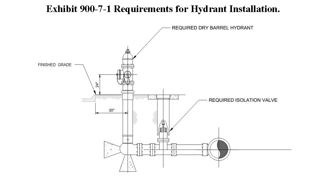
Sec. 900-7.5 - Design criteria for potable water systems.
A.
General. Central water systems shall be designed, constructed, placed into service and operated per the requirements of Louisiana Administrative Code, Title 51 (Sanitary Code), Louisiana Administrative Code, Title 56 (Public Works), and Recommended Standards for Water Works as promulgated by the Great Leaks Upper Mississippi River Board of State and Provincial Public Health and Environmental Managers, Latest Edition; except as otherwise provided for or modified herein.
B.
Layout of Water Utilities in the Right-of-way.
1.
Water utilities shall be located outside of streets for all new developments. Water utilities shall be located on the opposite side of the road as sewerage utilities. Water utilities may be located under bike paths and sidewalks, incidental paving, driveways, and parking areas.
2.
In general, water mains and valves shall be located between the right-of-way line and top of ditch or subsurface drainage feature. A horizontal clearance of minimum 3 feet shall be maintained between the top of ditch (or subsurface drainage feature) and edge of the main and/or valve. Under no circumstances shall valves and their access be constructed in ditches or under subsurface drainage features.
C.
Design Basis. System production, storage, and distribution systems including the water source and treatment facilities shall be designed for maximum day demand at the design year. Other than surface water intakes, all water supply facilities and water treatment plant access roads shall be protected to at least the 100-year flood elevation or maximum flood of record.
D.
General Considerations.
1.
The water distribution network shall consist of pipes, fittings, and other appurtenances designed to convey potable water at adequate quality, pressure, and discharge. Water mains shall be designed, constructed and properly connected with the public water supply system in such a manner as to adequately serve all lots shown on the subdivision plat for both domestic and fire water service purposes and shall comply with the requirements of this code.
2.
The water distribution network shall be in accordance with the standards and requirements set forth by the utility provider who will own and maintain said infrastructure.
3.
The maximum design velocity shall not exceed 5 fps. Water distribution systems shall be designed for the peak hourly flow or the maximum daily flow plus fire flow, whichever is greater.
4.
Treatment systems shall be designed and constructed to comply with the National Primary Drinking Water Regulations and Secondary Drinking Water Standards as promulgated by the United States Environmental Protection Agency in place at the time of approval of the plans and specifications for the system.
5.
All materials used in treatment systems shall meet the requirements of and be listed as compliant with NSF 61. All materials shall be lead free.
6.
Disinfection. Disinfection shall be provided by chlorine or chloramines and shall be designed to produce the required residual concentrations as promulgated within Louisiana Administrative Code, Title 51 (Sanitary Code). Ultraviolet disinfection shall not be utilized for Central Water Systems. Where free chlorine is used for disinfection, a secondary chemical feed point shall be included to allow for future use of chloramines. Chemical feed equipment for ammonia is not required for systems which employ free chlorine for disinfection.
Sec. 900-7.6 - Construction criteria for potable water systems.
A.
Applicability. The water distribution network shall be in accordance with the standards and requirements set forth by the utility provider who will own and maintain said infrastructure and minimum state standards.
B.
General.
1.
All materials used in potable water distribution shall meet the requirements of and listed as compliant with NSF 61. All materials shall be lead free.
2.
The applicant shall assume the responsibility for the layout of the work.
3.
Parallel sewer lines and water lines shall be laid in separate trenches with a minimum horizontal clearance between all water lines and all sewer lines of 10 feet. The minimum horizontal clearance between gravity sewer lines and sewer force mains shall be 10 feet. In the event a water line crosses over a sewer line, the minimum vertical clearance shall be 18 inches between the water and sewer lines. All water lines shall be above sewer lines. Any clearances less than the above mentioned shall subject to approval of the Department of Utilities (for systems to be dedicated to St. Tammany Parish Department of Utilities) or the Department of Engineering (for other systems).
4.
Minimum horizontal clearances of 5 feet and minimum vertical clearance of 18 inches shall be maintained between water lines and other utilities, such as communication lines, subsurface electrical lines, and gas lines. If water lines and sewer lines are located on opposite sides of the street/road, the subsurface electrical line shall be located on the same side as the sewer line.
5.
The cover between the top of pipe for all water mains and finished grade shall be at least 3' for landscaped/unimproved areas and 3' under roads.
C.
Excavation, Bedding, and Backfilling. The applicant shall provide all excavation required for the installation of water systems in accordance with the approved plans and the requirements of this code. Excavations for water lines and structures shall be prepared, bedded, and backfilled in accordance with the requirements below and as shown on the approved plans. Directional drilling under roadways may be uncased provided proposed improvements comply with LADOTD standards and are reviewed and approved by the utility company in accordance with this UDC. Should the utility company require directional drilling to be cased, the developer must comply with this direction to be considered in compliance with this UDC.
D.
Testing and Disinfection. All new water mains shall undergo hydrostatic testing to verify leak tightness. New water mains shall be tested a 125 psi for 2 hours. There shall be no pressure drops during the test. In the event the water main fails the test, the water main pipes shall be checked and repaired accordingly. The water main shall be re-tested.
E.
Fire Hydrants.
1.
Fire hydrants shall products approved by the Department of Utilities (for systems to be dedicated to St. Tammany Parish Department of Utilities) or the Department of Engineering (for other systems) with built-in check valve. All fire hydrants shall be of the dry barrel type complying with the requirements of AWWA C502. Fire hydrants shall have at least 3 outlets per hydrant, and all outlets shall have national standard threads. One outlet shall be a 5½ inch pumper connection, and 3 outlets shall be 2½ inch hose connections.
2.
All fire hydrants shall have a minimum of 24 inches of clearance between finished grade and the bottom of the 2½ inch outlet. If the fire hydrant becomes buried or the clearance is less than the required 24 inches, the applicant shall raise the fire hydrant at his expense to achieve the minimum required clearance. The Department of Utilities (for systems to be dedicated to St. Tammany Parish Department of Utilities) or the Department of Engineering (for other systems) will not accept the development until all fire hydrants have the required ground clearance. If the fire hydrant becomes buried after the Department of Utilities (for systems to be dedicated to St. Tammany Parish Department of Utilities) or the Department of Engineering (for other systems) accepts the water infrastructure as a result of the building construction, The Department of Utilities will not install a water meter to service the property until the fire hydrant is uncover or raised. The responsibility of uncovering or raising the fire hydrant shall be the responsibility of the applicant.
3.
Fire hydrants shall have a 6 inch diameter ductile iron lead an approved 6 inch diameter gate valve for isolation from the water main.
4.
Fire hydrants shall be located at least 6 feet, or greater as necessary by regulatory requirement, from the edge of roadway pavement.
5.
A minimum of 3 fire hydrants in the development shall be tested to verify actual fire flow and to classify the fire hydrants by observed flow rates. The number and selection of hydrants shall be determined by the local fire protection district. Representatives of the Department of Utilities (for systems to be dedicated to St. Tammany Parish Department of Utilities) or the Department of Engineering (for other systems) and the local fire protection district shall be present to observe fire flow testing and results.
6.
After fire flow testing, the applicant shall paint the top and the three outlet caps of each fire hydrant in accordance with the requirements of this UDC.
F.
Water Service Connections.
1.
Water service connections shall have a brass tapping saddle, brass corporation stop, and a minimum l inch connection size. Service connection piping shall be AWWA C901 polyethylene tubing, PE3408, D9. Water service connection shall have maximum cover of 2 feet.
2.
The location of the water service connections shall be stamped in the curb face or road surface using an approved "w↑" symbol and the symbol shall be at least 4 inches by 8 inches. The arrow shall point in the direction of the water service connection.
3.
Upon installation of the water service, a 2 inch by 2 inch stake with a florescent blue flag/streamer or painted florescent blue shall denote the location of the water service. Florescent blue shall be used for ease of locating by Department of Utilities (for systems to be dedicated to St. Tammany Parish Department of Utilities) or the Department of Engineering (for other systems) inspectors. The water service "whip" shall be tied to the stake as shown in the water service detail. The stake shall extend at least 3 feet from the existing ground surface. The stake must be maintained by the applicant until the residence or building has been connected to the service line.
4.
A 2-inch waterline shall wrap around each cul-de-sac but shall not tie back into the water main. Each cul-de-sac shall have a 2 inch blow off located at the end of the 2-inch waterline. Lines shall stop at the blow-off point.
5.
Representatives of the Department of Utilities (for systems to be dedicated to St. Tammany Parish Department of Utilities) or the Department of Engineering (for other systems) shall be present on-site for all testing required for the acceptance of the development. The applicant shall contact the Department of Utilities (for systems to be dedicated to St. Tammany Parish Department of Utilities) or the Department of Engineering (for other systems) at least 48-hours prior to testing.
6.
All water service connection shall be located at the lot line. Water service connections shall not be located within the driveway.
7.
One sample station shall be installed between valves on the water main or between a valve and dead-end or cul-de-sac.
8.
All new sample stations shall be a product approved by the Department of Utilities (for systems to be dedicated to St. Tammany Parish Department of Utilities) or the Department of Engineering (for other systems).
G.
Record Drawings.
1.
The applicant shall record horizontal and vertical location of all new water infrastructure. The applicant shall provide "red line drawings" to the Department of Utilities (for systems to be dedicated to St. Tammany Parish Department of Utilities) or the Department of Engineering (for other systems) upon completion of construction. The applicant shall verify and certify elevations, depths and location of water infrastructure when preparing the record drawings/as-built plans for the project.
2.
The Department of Utilities (for systems to be dedicated to St. Tammany Parish Department of Utilities) or the Department of Engineering (for other systems) will not accept the project until the applicant provides an accurate, verified set of record drawings/as-built plans for the project.
3.
The record drawings/as-built plans shall contain the following sheets of information:
a.
All sheets shall be stamped with the block "record drawings" or "as-built plans" and shall be dated.
b.
Title sheet with an index of sheets. Additional sheets to capture changes via change-order/plan change shall be listed in the index of sheets and be added at the end of the plan set.
c.
General notes and legend. Strike-through notes which do not apply.
d.
Site vicinity map showing new water and sewer infrastructure and tie-in location to the existing system(s).
e.
Overall water plan and site/street specific water plans shall be provided as needed to show additional information and clarity. Conflicts and offsets shall be called out on all water plans.
f.
Summary of material quantities. Final quantities for all installed materials (i.e. pipe, all valves, fire hydrants, etc.) Shall be provided.
g.
Summary of valves and fittings. Information regarding the valves and fittings shall be tabulated. The location of each valve, tee, cross, and bend shall be determined by measuring along the centerline of the water main from fitting to fitting or valve to fitting. Tabulations shall be from street intersection to street intersection. The size, type, manufacture and model of the valves and fittings shall be recorded in the summary tabulations as applicable. The top-of-casting elevation of the valve housing shall recorded and noted in the summary of valves and fittings.
4.
The applicant's redline drawings shall not be substituted for or accepted by Department of Utilities (for systems to be dedicated to St. Tammany Parish Department of Utilities) or the Department of Engineering (for other systems) as record drawings/as-built plans.
5.
The applicant shall provide record drawings/as-built plans in the following formats and quantities:
a.
Three full-size 22 inch by 34 inch hard copies,
b.
One copy in pdf format, and
c.
One copy in AutoCAD 2016 format. The Department of Utilities will not issue a letter of acceptance until record drawings/as-built plans have been provided.
Sec. 900-8.1 - Generally.
A.
General.
1.
Any private person or political entity who/which owns, leases or otherwise maintains or possesses control of any property which is situated in the unincorporated portion of the parish, and on which there is located a residence, camp, trailer coach or any other building, structure or establishment wherein people customarily or occasionally live, work or congregate, shall connect any such premises to a sewerage system as may be required for the premises by applicable law.
2.
Any private person or political entity who/which owns, leases, or otherwise maintains or possesses control of any property which is situated in the unincorporated portion of the parish and on which there is located a residence, camp, trailer coach or any other building, structure or establishment wherein people customarily or occasionally live, work or congregate, shall, at such person's sole expense, connect any such premises to a public sewerage system if such public sewer line is situated within 300 feet of the boundary line of such premises. Such construction to connect the premises shall commence within the time required by R.S. 33:4042, upon receipt of a notice to connect. If such connection is not begun in the time required, the parish may connect the premises to the public sewer in the manner prescribed by R.S. 33:4041 et seq., and apportion the connection costs and fees to each owner as also provided therein. The parish shall have all other remedies for enforcement and collection of connection costs and fees as is provided by applicable law.
3.
No certificate of occupancy shall be issued before sewerage systems are installed and operable or until the development is otherwise connected to a community (central) sewerage system approved by the Department of Environmental Services or assignee.
4.
General provisions. For the purpose of complying with R.S. 33:4064.6(A), the provision of sewage disposal by use of community sewerage systems is a best management practice which results in the protection of public health and the environment.
5.
Every responsible person shall know, be familiar with, and comply with the provisions of these regulations.
6.
Whenever facts and circumstances exist whereby the Department of Environmental Services determines that a responsible person has acted in a manner contrary to or inconsistent with the provisions and requirements set + the department (hereinafter referred to as the "deficiency"), the department shall cause to be issued to said responsible person a notice which cites the deficiency, directs compliance with the rules and regulations of the department, and prescribes a reasonable amount of time to accomplish such direction.
7.
If no or insufficient action is taken after proper notice, the department, upon expiration of the time prescribed in said notice, shall be authorized to impose upon said responsible person, as defined in this section, a penalty not to exceed $100.00 per day for each day the deficiency existed from date of said notice, however, the cumulative total of such penalty shall not exceed $10,000.00. In addition thereto, the department may terminate or require the termination of any utility service to the subject premises.
8.
As further provided by applicable law, the Department of Environmental Services shall be authorized to enforce the collection of an imposed penalty, such to include the filing of an affidavit of lien on the subject property or any property found or within the parish which is owned by the responsible party.
9.
Any responsible person who has been assessed a penalty may appeal the imposition of the penalty in writing to the Parish Council within 30 days. The Parish Council shall thereafter hear the appeal at a public hearing at its next regular meeting. An appeal from the Council's decision shall be to the 22nd Judicial District Court for the parish within 30 days of the council's decision.
10.
The Department of Environmental Services shall be authorized to recommend or prescribe additional procedures or practices he deems necessary and advisable to effect the provisions of this section.
11.
For the purposes of this section, the term "community sewerage system" means any sewerage system which consists of a collection and/or transport system which serves multiple connections and/or a pumping facility and/or a treatment facility; and the term "facility" means any and all the apparatus and appurtenances which may be associated with the subject element of the community sewerage system and may mean more than one facility.
12.
Every governed sewerage system or governed water system shall be constructed or modified in accordance with the plans and specifications for installation which have been approved in advance by the department prior to the start of construction or modification.
13.
Whenever any person commences any activity or action to connect to, or to otherwise construct or modify a sewerage or water system without first having complied with the applicable provisions of this article, then, in addition to all other remedies provided by applicable law, the department shall be entitled to collect a fee equal to 200 percent of the established fee otherwise due for said activity or action.
14.
The provisions of this article shall have force and effect within the unincorporated portion of the parish.
15.
Nothing in these rules and regulations shall be construed to preclude, stay or otherwise preempt the state health officer or other such regulatory authority from imposing more stringent requirements which relate to the construction or discharge of sewage effluent from a non-community-type sewerage system.
B.
When Required.
1.
Community sewerage shall be provided for all developments for which the following criteria are met:
a.
Sewage effluent cannot be disposed of on site in accordance with the requirements of LAC Title 51 (Sanitary Code).
b.
Whenever a discharge permit for individual systems can be obtained from the Department of Environmental Quality (LDEQ).
c.
Whenever the Department of Environmental Services determines that a subdivision or development which is subject to the provisions of this code is in proximity to the sewage collection or treatment facility of a qualified community sewerage system, said subdivision or development shall be required to connect thereto.
2.
For the purposes of this subsection, the term "qualified community sewerage system" means a community sewerage system:
a.
Which has the actual and/or anticipated capacity which will be required to realize the peak sewage demand of the subject subdivision or development; and
b.
The operation and maintenance of which is likely to be in accordance and compliance with all regulatory requirements; all as determined by the Department of Environmental Services.
C.
Construction or Modification of a Sewerage System.
1.
The requirements set forth in R.S. 33:4064.1 et seq. and as further provided in the rules and regulations of the Department of Environmental Services of the Parish, the Department of Environmental Services shall have authority over all construction necessary or incidental to the provision of sewage disposal in the unincorporated portion of the parish. Plans and specifications for a community sewerage system to be constructed in said portion of the parish shall be submitted to and approved by the Department of Environmental Services prior to initiating such construction, and the conduct of such construction shall be subject to inspection by the Department of Environmental Services. Copies of any amendments to plans and specifications for such systems shall also be submitted to the Department of Environmental Services, and the Department of Environmental Services shall approve such amendments prior to operation of such systems.
2.
Prior to the start of construction or modification of a community sewerage system, detailed plans and specifications shall be submitted by the applicant for the system to be constructed or modified and shall be reviewed and, contingent upon any revisions to such plans and specifications as may be required to meet compliance, approved by the Department of Environmental Services in accordance and compliance with applicable law which shall include the relevant provisions of Title 51 of the Louisiana Administrative Code (Sanitary Code).
3.
Whenever an existing community sewerage system is designated for connection to a proposed subdivision or development, the detailed plans and specifications shall include the discharge permit number issued by the Louisiana State Department of Environmental Quality.
D.
Approval by Department of Environmental Services.
1.
As such relates to the provisions this code, whenever there is a participatory and coordinated effort between the Department of Environmental Services and the District Engineer of the Louisiana Department of Health, Office of Public Health, the Department of Environmental Services shall affirm that the community sewerage system is in accordance and compliance with applicable laws.
2.
If after 1 year from the date on which such approval was granted the proposed construction or modification is not complete, any approval or affirmation thereof by the Department of Environmental Services shall be void. Accordingly, prior to the conduct of any proposed or subsequent construction or modification, the responsible party shall again comply with the provisions of this code.
a.
However, in response to a written application from the applicant, the Department of Environmental Services may approve a conditional or absolute waiver of the effect of the provisions of this section.
b.
Any review and subsequent approval of the plans and specifications for the construction or modification of a community sewerage system is for the use and benefit of the Department of Environmental Services and shall not be considered as an affirmation that the construction, modification, or operation of the system is or will be in accordance or compliance with applicable law which shall include the relevant provisions of which shall include the relevant provisions of Title 51 of the Louisiana Administrative Code (Sanitary Code).
3.
Every community central sewerage system shall be constructed or modified in accordance with the plans and specifications for installation which have been approved in advance by the Department of Environmental Services prior to the start of construction or modification.
E.
Inspections.
1.
To monitor the construction or modification of any community sewerage system, the Department of Environmental Services may authorize any employee or agent of the Department of Environmental Services to inspect at a reasonable time and in a reasonable manner any such system in order to determine that its construction or modification is conducted in accordance and compliance with the plans and specifications for installation which have been approved in advance by the Department of Environmental Services. In carrying out this power, said authorized employee or agent may enter private and public properties. As such relates to the provisions of this section, whenever there is a participatory and coordinated effort between the department and the parish engineer, the department shall acknowledge the results of any inspection conducted by the Department of Environmental Services.
2.
Any inspection of a community sewerage system pursuant to a provision of this section is for the use and benefit of the Department of Environmental Services and shall not be considered as an affirmation that the construction, modification, or operation of the inspected system is or will be in accordance or compliance with applicable law.
3.
The provision of sewage disposal shall not occur until the constructed or modified community sewerage system has been inspected by the Department of Environmental Services or their designee or by the appropriate state authority and determined to be constructed or modified in accordance with the applicable and appropriate plans and specifications which have been approved in advance by the Department of Environmental Services and/or appropriate state authority. Prior to the granting of As Built Plan approval by the parish Planning Commission, the as-built drawings and detail sheets for the system, as prepared by a licensed professional engineer, shall be submitted to the Department of Environmental Services for their review and comment.
4.
Responsibility and authority of the Department of Environmental Services. As such relates to any or all of the provisions of this section and to the extent provided in R.S. 33:4064.1 et seq., the Department of Environmental Services is authorized to adopt rules and regulations, the purpose of which shall be to plan, adjust, and relocate community sewerage systems within the unincorporated portion of the parish to conform with this development plan and, to that end, the Department of Environmental Services shall establish rules and regulations, objective standards, guidelines, and practices which may be necessary to effect the provisions of this section or may avail themselves of the provisions of R.S. 33:4064.5(D), or both.
Sec. 900-8.2 - Connections to parish system.
A.
Fees for Planning.
1.
The fee assessed to review plans and specifications for the construction or modification of any sewerage or water system or systems, the construction or modification of which is associated with a subdivision development proposed for approval by the parish planning commission shall be in accordance with the provisions of the parish Ordinance No. 91-1470, to-wit: $10.00 per lot upon application for concept plan approval; $20.00 per lot upon application for Final Plat and Construction Plan approval; and $30.00 per lot upon application for final plan approval.
2.
The fee assessed to review the plans and specifications for the construction or modification of a governed water system shall be:
a.
Ten dollars plus $0.04 per each linear foot of water distribution pipe to be constructed or modified, and/or $0.06 per each linear foot of sewage collection pipe to be constructed or modified in addition to $10.00 per water supply facility (e.g., well) to be constructed or modified, and/or per sewage collection or treatment facility (e.g., plant, pond, lift station) to be constructed or modified.
3.
It is the intent of the provisions of this section that a water supply facility or a sewage collection or treatment facility shall mean the individual, distinct components, respectively of a governed water system or governed sewerage system. Hence, a sewage treatment system with one or more aerated lagoons and associated pumping and treatment infrastructure in immediate proximity thereto shall be considered one sewage treatment facility. However, an associated, but remote lift station shall be considered a separate sewage collection facility. Manhole access points shall not be considered a separate sewage collection facility, but merely an element of the linear footage of the sewage collection piping.
4.
Any fee assessed pursuant to a provision of this section shall be due and payable in full to the department upon the ordinary application for subdivision plan approval by the parish planning commission, as provided by an ordinance of the parish, or otherwise upon the submittal of the detailed plans and specifications to the department by the responsible person for the governed sewerage system or governed water system to be constructed or modified. Upon collection of any fee assessed pursuant to a provision of this section, such fee shall be placed into a special fund, the use of which shall be for the administration of the provisions of this section which relate to the review of plans and specifications for the construction or modification of sewerage or water systems.
B.
Fees for Inspections. The fee assessed to inspect the construction or modification of a governed water system shall be:
1.
$0.12 per each linear foot of water distribution pipe to be constructed or modified, and/or $0.22 per each linear foot of sewage collection pipe to be constructed or modified; in addition to $60.00 per water supply facility (e.g., well) to be constructed or modified, and/or per sewage collection or treatment facility (e.g., plant, pond, lift station) to be constructed or modified.
2.
Any fee assessed pursuant to a provision of this section shall be due and payable in full to the department upon application for Final Plat and Construction Plan approval by the parish planning commission, or otherwise, upon the submittal of the detailed plans and specifications to the department by the responsible person for the governed sewerage system or governed water system to be constructed or modified. Upon collection of any fee assessed pursuant to this section, such fee shall be placed into a special fund, the use of which shall be for the administration of the provisions of this section which relate to the inspection of sewerage or water systems to be constructed or modified.
(Ord. No. 25-5781, § Exh. A, 7-10-2025)
Sec. 900-8.3 - Monitoring.
A.
General.
1.
Monitoring of Sanitary Sewerage System. Every governed sewerage system shall make available to the department for its review, upon the department's request, all monitoring data required to be furnished to the Louisiana Department of Environmental Quality (DEQ) as set forth in the discharge permit issued by the DEQ for the treatment works for the system. Such monitoring data shall be reported on a discharge monitoring report (DMR) form (EPA No. 3320-1 or an approved substitute). For inspection purposes, copies of all such monitoring reports shall be kept on-site at, or in reasonable proximity to, the permitted facility for a period of at least 3 months from the date of the sample measurement or report of such measurement.
2.
Every sewerage system whose discharge of sanitary is subject to provisions of Louisiana Environmental Quality Act, as amended, or any rules and regulations effective or promulgated under authority of said Act shall obtain a Louisiana Pollution Discharge Elimination System (LPDES) permit in accordance and compliance with applicable law, and shall comply with the provisions set forth in the LPDES permit, or any order or directive issued by the DEQ which related to the/a LPDES permit.
Sec. 900-8.4 - Required disposal of sewerage effluent.
A.
General.
1.
All new or existing premises, public or private, where people live, work or congregate shall be provided with approved toilet facilities, including hand washing facilities. Such plumbing facilities shall be properly connected to a community sewerage system, whenever available, or to an individual on-site sewage disposal system which is specifically approved for the premises by the state health officer or his duly authorized representative after determining that the installation and operation of an individual on-site sewage disposal system will not create a nuisance or public health hazard.
2.
It shall be the duty of the owner, manager or agent of any occupied premises, public or private, where people live, work or congregate to provide the premises with an approved method of sewage disposal in compliance with the requirements of this code.
3.
Whenever the DES determines that any building or structure to be constructed is in proximity to the sewage collection or treatment facility of a qualified community sewerage system, said building or structure shall be required to connect thereto. When a qualified community sewerage system is available, and there is an approved public water supply with adequate water capacity, all plumbing fixtures within any building or structure shall be connected to such approved public water supply and community sewerage system. For purposes of this section, the term "qualified community sewerage system" means a community sewerage system:
a.
Which has the actual and/or anticipated capacity which will be required to realize the peak sewage demand of the subject building or structure; and
b.
The operation and maintenance of which is likely to be in accordance and compliance with all regulatory requirements; all as determined by the DES.
4.
Every non-community-type sewerage system to be installed in the unincorporated portion of the parish shall be so constructed that the disposal of its sewage effluent is realized essentially within the boundaries of the building site upon which the sewage effluent originated by means of an approved post-secondary treatment sewage effluent disposal method.
Sec. 900-8.5 - Wastewater standards prior to entering collection systems of St. Tammany Parish.
A.
General.
1.
Pursuant to R.S. 33:4064.4(C), the Parish Department of Environmental Services "shall be authorized to adopt rules and regulations relative to the impact upon, and the construction, modification, perpetuation, sustenance, operation, maintenance, connection and inspection of sewerage systems and the provision and/or supervision of environmental services, all within the unincorporated portion of the parish."
2.
Wastewater generated from the industrial and light industrial customers shall not exceed the following standards prior to said wastewater entering the wastewater collection systems owned and operated by the parish:
Exhibit 900-8-1 Industrial Wastewater Standards.
3.
Failure by any customer to provide this quality wastewater prior to treatment by the parish shall result in termination of wastewater treatment services and/or water service at the sole discretion of the parish.
Sec. 900-8.6 - Septage and sludge development standards.
A.
General. Septage and sludge treatment facilities within the parish shall comply with all of the provisions of the state department of health and hospitals, hereinafter referred to as Department of Health and Hospitals or its successor agency, the sanitary code of the state and the department of environmental quality, hereinafter referred to as Louisiana Department of Environmental Quality or its successor agency, and the water quality control standards of the state.
B.
Plans and Specifications.
1.
Plans and specifications. The proposed applicant of a septage/sludge treatment facility shall be required to submit to Department of Environmental Services a complete set of plans and specifications along with the completed "Design Summary Package," as required by Louisiana Department of Health, detailing the type of septage/sludge treatment facility to be installed.
2.
Such plans and specifications shall be certified by a registered professional engineer of the state and submitted in triplicate.
3.
Upon review and approval of the plans and specifications by the Department of Environmental Services, the plans and specifications will be forwarded to the Louisiana Department of Health for their approval.
C.
Construction Time Limitations. The applicant must comply with the time limitations as provided by LDH with respect to their approval, and those of Louisiana Department of Environmental Quality concerning the discharge permit.
D.
Operations and Maintenance.
1.
The applicant shall be responsible for the operation and maintenance at his expense, of the septage/sludge treatment facility and further compliance with all requirements of this article and with federal and state laws and regulations. This may include hiring of a certified operator, or a consultant that provides such a service, and adhering to the instructions and limits as laid out in the Louisiana Department of Environmental Quality discharge permit.
2.
Initial start-up of operations at newly constructed facilities shall not commence until the Department of Environmental Services has been provided with as-built drawings certified by a licensed engineer and a copy of the final Louisiana Department of Environmental Quality discharge permit.
E.
Management of Facilities and Transfer of Ownership.
1.
The applicant for a septage/sludge treatment facility may transfer the ownership rights to another party if so desired. However, in any case, the applicant shall establish and submit to the department, a "Management Declaration" which shall establish the responsibility of the applicant or the transferee for the operation and maintenance and funding requirements for the septage/sludge treatment facility.
2.
The applicant must satisfy the concerns of the parish and of Louisiana Department of Health for their approval that said transferee is valid, solvent and capable of meeting all applicable rules and regulations.
Sec. 900-8.7 - Design criteria for sewerage systems.
A.
General. Central sewerage systems shall be designed, constructed, placed into service and operated per the requirements of Louisiana Administrative Code, Title 51 (Sanitary Code), and Recommended Standards for Wastewater Works as promulgated by the Great Lakes Upper Mississippi River Board of State and Provincial Public Health and Environmental Managers, Latest Edition; except as otherwise provided for or modified herein.
B.
Layout of Utilities in the Rights-of-way.
1.
Sewerage utilities shall be located outside of streets for all new developments. Water utilities shall be located on the opposite side of the road as sewerage utilities. Sewerage utilities may be located under bike paths, sidewalks, incidental paving, driveways, and parking areas.
2.
In general, gravity sewerage mains and force mains and valves shall be located between the right-of-way line and top of ditch or subsurface drainage feature. A horizontal clearance of minimum 3 feet shall be maintained between the top of ditch (or subsurface drainage feature) and edge of the gravity main, force main and/or valve. If the clearance requirement cannot be met due to field conditions, the Applicant shall coordinate with the Department of Public Works to determine an acceptable location of the main and/or the valve. Under no circumstances shall valves and their access be constructed in ditches or under subsurface drainage features.
C.
Design Basis. System conveyance and treatment facilities shall be designed for maximum day demand at the design year. All wastewater treatment facilities shall be protected to at least the 100-year flood elevation or maximum flood of record.
D.
General Design Considerations. In addition to the requirements of Louisiana Administrative Code, Title 51 (Sanitary Code), and Recommended Standards for Wastewater Works as promulgated by the Great Leaks Upper Mississippi River Board of State and Provincial Public Health and Environmental Managers, Latest Edition; the applicant shall adhere to the following requirements:
1.
Loadings. Sewerage loadings for plants and collection systems shall be determined by the Sewerage Loading Criteria of Louisiana Administrative Code, Title 51 (Sanitary Code) or the requirements of Louisiana Administrative Code, Title 51 (Sanitary Code), whichever provides the most stringent requirements.
2.
Design of Sewers. Gravity sewer shall be designed in accordance with the requirements of Chapter 30 - Sewers contained within Recommended Standards for Wastewater Works as promulgated by the Great Lakes Upper Mississippi River Board of State and Provincial Public Health and Environmental Managers, Latest Edition. Gravity sewers shall be designed for a minimum velocity of 2 feet per second and a maximum velocity of 8 feet per second.
3.
Minimum cover over gravity mains. The minimum cover over gravity mains shall be 3 feet in unpaved areas and 5 feet under roadways. All manhole rim elevations shall be at finished grade in paved areas and 6 inches above finished grade in unpaved areas.
4.
Force Mains. Gravity sewer shall be designed in accordance with the requirements of Chapter 40—Force Mains contained within Recommended Standards for Wastewater Works as promulgated by the Great Leaks Upper Mississippi River Board of State and Provincial Public Health and Environmental Managers, Latest Edition. Force mains shall be designed for a minimum velocity of 3 feet per second with one pump operating at its lowest speed and a maximum velocity of 8 feet per second with all pumps operating at their maximum speed. Air release, air vacuum, and combination air valves shall be provided along all force mains to preclude hydraulic lock of the force main.
5.
Sewerage Pumping Stations. The use of sewer lift stations should be minimized. However, when pump stations cannot be avoided, they shall be designed for ease of maintenance, consistent operation, and a long service life of continuous operation in a harsh operating environment. Sewerage pumping stations shall be designed in accordance with the requirements of Chapter 40 - Force Mains contained within Recommended Standards for Wastewater Works as promulgated by the Great Lakes Upper Mississippi River Board of State and Provincial Public Health and Environmental Managers, Latest Edition, NFPA 70 - National Electrical Code (Latest Edition), and NFPA 820 - Standard for Fire Protection in Wastewater and Collection Facilities (latest edition).
a.
Sewerage pump stations shall be of the submersible type found suitable per the utility provider specifications.
i.
A minimum of 2 submersible pumps, each of which has capacity to handle the design flow;
ii.
Rail system which allows for removal of the pumps without entry into the wet well;
iii.
Check valves and isolation valves contained within a separate below grade vault;
iv.
Adequate controls with overload and lightning protection and alternators.
v.
Necessary servitudes, access roads, driveways, and security fencing.
vi.
All conduits entering hazardous areas shall be sealed in accordance with the requirements of NFPA 70.
vii.
Sufficient wet well storage such that no pump shall be required to start more than 12 times per hour at design flow.
b.
Servitudes shall extend a minimum of 10 feet beyond any components of a sewer lift station in every direction. The parish may require additional servitudes if deemed necessary.
c.
Sewer lift stations shall not be constructed on public right-of-way. Sewer lift stations shall be constructed on private property and within a sewer servitude dedicated to the parish.
6.
Control Panels. Per utility provider requirements, each sewerage pumping station shall be provided with a control panel to provide un-attended automatic operation of pumps. Panels shall be completely assembled, wired, and tested. Panel manufacturers shall be certified by Underwriters Laboratories, (UL) to manufacture UL 508A and 698A control panels.
7.
Sewer Pumps. Sewer pumps shall of the submersible non clog or submersible grinder type, be of cast iron construction, or as found suitable per utility provider requirements for long term immersion in and pumping of raw, unscreened sewerage.
8.
Wet Wells and Valve Pits. Wet wells and valve pits shall be constructed in accordance with utility provider specifications.
9.
Treatment Facilities. Treatment facilities shall be designed and constructed in accordance with the of Louisiana Administrative Code, Title 51 (Sanitary Code), and Recommended Standards for Wastewater Works as promulgated by the Great Lakes Upper Mississippi River Board of State and Provincial Public Health and Environmental Managers, Latest Edition, and the site - specific discharge permit issued by the Louisiana Department of Environmental Quality. Treatment facilities shall also comply with the requirements of NFPA 70 - National Electrical Code (Latest Edition), and NFPA 820 - Standard for Fire Protection in Wastewater and Collection Facilities (latest edition).
a.
Wastewater treatment facilities may employ any of the following technologies:
i.
Activated Sludge;
ii.
Trickling Filters;
iii.
Partial Mix, Complete Mix Aerated Lagoons;
iv.
Moving Bed Biological Reactors;
v.
Fixed Growth Biological Reactors; and
vi.
Sand or other media filtration.
b.
The following treatment technologies may not be employed:
i.
Facultative Lagoons
c.
Gaseous chlorine and sodium hypochlorite, and ultraviolet disinfection shall be acceptable methods of disinfection.
10.
Low Pressure Sewerage Systems. The Department of Utilities will not accept ownership of low-pressure sewerage systems.
Sec. 900-8.8 - Construction criteria for sewerage systems.
A.
General.
1.
The applicant shall provide all work necessary for the construction of sewerage collection and treatment systems to be installed.
2.
The Director of the Department of Engineering, with the concurrence of the Director of the Department of Utilities, may waive these construction criteria when alternate minimum standards are proposed which in their opinion will provide for acceptable quality of construction.
3.
The Department of Utilities will witness testing performed for systems to be dedicated to St. Tammany Parish Department of Utilities. The Department of Engineering will observe testing for other systems.
4.
The applicant shall provide a one-year warranty for all newly installed sewerage infrastructure associated with the construction of the project, including but not limited to gravity sewer pipelines, manholes, force mains, sewerage pumping stations, valves, and treatment facilities. The warranty shall extend for a period of one year from the date of final acceptance. The applicant shall furnish all materials and labor required to correct deficiencies in the system at the expense of the Applicant.
5.
The applicant shall assume the responsibility for the layout of the work.
6.
Parallel sewer lines and water lines shall be laid in separate trenches with a minimum horizontal clearance between all water lines and all sewer lines of 10 feet. The minimum horizontal clearance between gravity sewer lines and sewer force mains shall be 6 feet. In the event a water line crosses over a sewer line, the minimum vertical clearance shall be 18 inches between the water and sewer lines. All water lines shall be above sewer lines. Any clearances less than the above mentioned shall subject to approval of the Department of Public Works.
7.
Minimum horizontal clearances of 5 feet and minimum vertical clearance of 18 inches shall be maintained between water lines and other utilities, such as communication lines, subsurface electrical lines, and gas lines. If water lines and sewer lines are located on opposite sides of the street/road, the subsurface electrical line shall be located on the same side as the sewer line.
B.
Excavation, Bedding, and Backfilling. The applicant shall provide all excavation required for the installation of sewerage systems in accordance with the approved plans and the requirements of this code. Excavations for sewerage lines and structures shall be prepared, bedded, and backfilled in accordance with the requirements below and as shown on the approved plans.
1.
Bedding and Backfilling. Sewer force main bedding and backfill shall be in compliance with requirements set forth by the utility provider.
2.
Compaction. Compaction regulations shall be in accordance with utility provider specifications.
3.
Pipe and Fittings. New sewerage force mains installed, colored, and labelled per utility provider specifications.
4.
Drilling.
a.
Directional drilling. Directional drilling under roadways may be uncased provided proposed improvements comply with LADOTD standards and are reviewed and approved by the utility company in accordance with this UDC. Should the utility company require directional drilling to be cased, the developer must comply with this direction to be considered in compliance with this UDC.
b.
Drilling logs. Upon completion of sewerage force main construction, the drilling logs for all HDD installed sewerage force mains shall be provided with the record drawings/as-built plans. The drilling logs shall follow specifications made by the utility provider.
5.
Pipe specifications. Pipe sections and fitting specifications shall be in accordance with utility provider specifications.
6.
Pipe laying and installation. Pipe laying and installation shall be in accordance with utility company specifications.
7.
Manholes. The applicant shall provide sewer manholes of the type and dimensions indicated on the drawings in accordance with utility company specifications.
8.
Precast Concrete Riser Rings. New precast concrete riser rings free from cracks, voids and other defects and shall conform to utility company specifications.
9.
Cast Iron Riser Rings. New cast iron riser rings shall conform to utility company specifications.
10.
New pipe-existing pipe connections. Connections between existing and new pipe, with the exception of HDPE pipe, shall be jointed with non-shear repair couplings conforming to utility company specifications.
11.
Pipe-manhole Connections. All sewer pipe shall be connected to new manholes with connectors in accordance with utility company specifications.
12.
Service Lateral Connections. Connections between the existing service lateral and the new/rehabilitated sewer main line shall be in accordance with the contract documents. Existing sewer service lateral and house connections shall be adjusted as required avoiding conflicts with the new work. New pipe and fittings shall be furnished and installed as necessary and in accordance with the contract documents.
a.
Service lateral connections located within the limit of a rehabilitation method or repair are required to be replaced (regardless of construction method) in both directions up to the property line with a clean-out and pad installed at the property line. Construction shall be in accordance with the appropriate typical drawings in the Contract Documents. The exception to this is with service lateral connections on the mainlines to be rehabilitated with CIPP lining. In this case. Unless a point repair or remove and replace repair is shown on the plans, service lateral connections on mainlines to be CIPP lined will receive a lateral connection sealing and repair product (top hat) as specified herein.
b.
Service lateral vertical connection stacks shall be required in accordance with the contract documents.
c.
New service lateral terminations, required prior to private service connection and cleanout installation, shall be required in accordance with the contract documents and stubbed a minimum of 3 feet above ground and capped.
13.
Acceptance tests for new pipe. Installed sewer lines shall pass one or more of the following tests performed by the applicant. Applicant shall perform the test in the presence of the Department of Utilities (for systems to be dedicated to St. Tammany Parish Department of Utilities) or the Department of Engineering (for other systems) or of his representative. Applicant shall coordinate testing with surface restoration requirements of the approved plans. Any removal or replacement of temporary or final surface restoration by the applicant to investigate leaks shall be done so at the expense of the applicant. Sewer tests shall be tested for leakage as follows: Low air pressure test for sewer pipe 24 inch in diameter and smaller; infiltration test for sewer pipe greater than 24 inches in diameter with groundwater equal to or greater than 2 feet above top of pipe; and an exfiltration test should be used for sewer pipe greater than 24 inches in diameter with groundwater less than 2 feet above top of pipe.
a.
Low Pressure Test. This practice defines the proper procedures for acceptance testing of installed gravity sewer pipe using low-pressure air, to provide assurance that the pipe, as installed, is free from significant leaks. Included are requirements for equipment accuracy, safety precautions, line preparation, test method, and minimum holding times. Applicable sections of ASTM F1417 shall also apply.
i.
For pipes 36 inches in diameter and less (manhole to manhole reach), only lines tested after backfilling to final grade will be considered for acceptability. Acceptance will be dependent on a passing test. However, the installer as a presumptive test to determine the condition of the line prior to backfilling may also use this test. During sewer construction, all service laterals, stubs, and fittings into the sewer test section shall be properly capped or plugged to prevent air loss that could cause an erroneous air test result. It may be necessary and is always advisable for the applicant to restrain gasketed caps, plugs, or short pipe lengths with bracing stakes, clamps, and tie-rods or wire harnesses over the pipe bells.
ii.
Unless otherwise specified, the applicant shall furnish all the necessary equipment and be responsible for conducting all low-pressure air tests. In addition, the applicant shall be responsible for any necessary repair work on sections that do not pass the test at no additional cost to the owner.
iii.
The applicant should use mechanical or pneumatic plugs. All plugs shall be designed to resist internal testing pressures without the aid of external bracing or blocking. However, the applicant shall internally restrain or brace the plugs to the manhole wall as an added safety precaution throughout the test.
iv.
Air test gauges shall be laboratory-calibrated test gauges, and shall be recalibrated by a certified laboratory prior to the leakage test. Air gauges shall have a size and pressure range appropriate for the pipe being tested. All pressurizing equipment used for low-pressure air testing shall include a regulator or relief valve set no higher than 9 psig to avoid over-pressurizing and displacing temporary or permanent plugs. As an added safety precaution, the pressure in the test section should be continuously monitored to make certain that it does not, at any time, exceed 9 psig. (It may be necessary to apply higher pressure at the control panel to overcome friction in the air supply hose during pressurization.)
v.
To facilitate test verification by the Department of Utilities, all air used shall pass through a single, above ground control panel. The above ground air control equipment shall include a shut-off valve, pressure relief valve, input pressure gauge, and a continuous monitoring pressure gauge having a pressure range from 0 to at least 10 psi. The continuous monitoring gauge shall be no less than 4 inches in diameter with minimum divisions of 0.10 psi and an accuracy of plus or minus 0.04 psi. Two separate hoses shall be used to: 1) connect the control panel to the sealed line for introducing low-pressure air, and 2) a separate hose connection for constant monitoring of air pressure build-up in the line. This requirement greatly diminishes any chance for over-pressurizing the line.
vi.
If pneumatic plugs are utilized, a separate hose shall also be required to inflate the pneumatic plugs from the above ground control panel.
vii.
After a manhole-to-manhole reach of pipe has been backfilled to final grade and compacted, prepared for testing, and a 24-hour waiting period has elapsed, the plugs shall be placed in the line at each manhole and secured.
viii.
The applicant is advised to seal test all plugs before use. Seal testing may be accomplished by laying one length of pipe on the ground and sealing it at both ends with the plugs to be checked. The sealed pipe should be pressurized to 9 psig. The plugs shall hold against this pressure without bracing and without any movements of the plugs out of the pipe. No persons shall be allowed in the alignment of the pipe during plug testing. It is advisable to plug the upstream end of the line first to prevent any upstream water from collecting in the test line. This is particularly important in high groundwater situations.
ix.
When plugs are being placed, the pipe adjacent to the manhole shall be visually inspected to detect any evidence of shear in the pipe due to differential settlement between the pipe and the manhole. A probably point of leakage is at the junction of the manhole and the pipe, and this fault may be covered by the pipe plug, and thus not revealed by the air test.
x.
Low-pressure air shall by slowly introduced into the sealed line until the internal air pressure reaches 4.0 psig. If the groundwater table is above the sewer being tested, the air pressure shall be increased 0.43 psi for each foot that the water table is above the invert of the sewer, up to a maximum of 9.0 psig. After a constant pressure of 4.0 psig (greater than the average groundwater back pressure) is reached, the air supply shall be throttled to maintain that internal pressure for at least 2 minutes. This time permits the temperature of the entering air to equalize with the temperature of the pipe wall.
xi.
When temperatures have been equalized and the pressure stabilized at 4.0 psig (greater than the average groundwater backpressure), the air hose from the control panel to the air supply shall be shut off or disconnected. The continuous monitoring pressure gauge shall then be observed while the pressure is decreased to no less than 3.5 psig (greater than the average backpressure of any groundwater over the pipe). At a reading of 3.5 psig, timing shall commence with a stopwatch.
xii.
If the time shown for the designated pipe size and length elapses before the air pressure drops to 0.5 psig, the section undergoing time shall have passed. The test may be discontinued once the prescribed time has elapsed even though the 0.5 psig drop has not occurred. If the pressure drops 0.5 psig before the appropriate time has elapsed, the air loss rate shall be considered excessive and the section of pipe has failed the test.
xiii.
If the section fails to meet these requirements, the applicant shall determine at their own expense the source, or sources, of leakage, the installer shall repair or replace all defective materials or workmanship to the satisfaction of the Department of Public Works. The extent and type of repair, which may be allowed, as well as results, shall be subject to the approval of the Department of Public Works. The completed pipe installation shall then be retested and required to meet the requirements of this test.
b.
For Pipes Larger than 36" in Diameter (Individual Joint Testing). Individually test each sewer pipe joint with an approved joint air testing apparatus to an air pressure of 4.0 psig. If the groundwater table is above the sewer being tested, the air pressure shall be increased 0.43 psi for each foot that the water table is above the invert of the sewer, up to a maximum of 9.0 psig unless otherwise restricted by pipe manufacturer's recommendation. The testing apparatus shall be positioned within the pipe in such a manner as to straddle the joint to be tested.
i.
The apparatus packer ends shall be expanded so as to isolate the joint from the remainder of the pipe and create a void area between the packer and the pipe joint. The ends of the testing device shall be expanded against the pipe in accordance with the manufacturer's recommendations.
ii.
After void pressure is observed to be equal to or greater than the required test pressure, the air flow shall be stopped. If the void pressure drops by more than 1.0 psi within 15 seconds, the joint will have failed the test.
iii.
Upon completing the testing of each individual joint, the packer shall be deflated with the void pressure meter continuing to display void pressure. The applicant shall note and record the pressure display reading before each joint test. Should the void pressure meter fail to drop to 0.0 (±0.5) psig, the applicant shall make necessary equipment repairs to provide for an accurate void pressure reading.
c.
Infiltration Test. Where the natural groundwater is 24 inches or more above the top of a section of pipe, the applicant shall measure the flow of water in the pipe and the rates of seepage and infiltration. Applicant shall measure the flow rate by using a calibrated weir. The applicant shall leave the weir in the line until the flow rate has stabilized. The applicant is responsible for verifying the groundwater level by providing sight gauges in manholes or digging test holes at suitable locations.
i.
The total seepage and infiltration of groundwater as determined by the test shall in no case exceed 50 gallons per 24 hours per inch-mile of pipe.
ii.
The applicant shall make infiltration tests on all sewer construction before placing the lines in service and before making any connections to other sewers.
iii.
If the amount of infiltration into the sewer(s) is in excess of the maximum quantity specified above, then repair the joints, relay the sewer (if necessary), or perform other remedial construction, at the applicant's expense, in order to reduce groundwater infiltration to within the specified limits.
d.
Exfiltration Test. Where the groundwater is not 24 inches or more above the top of the pipe section being tested, the applicant shall perform an exfiltration test. The applicant shall bulkhead the pipe below the lower manhole of the section being tested with a pneumatic plug or other device. Insert a vent pipe 48 inches long in the stopper of the upper end of that section. Then fill the lower manhole with water or add water until there is a minimum of 4 feet over the upper end; make certain that all air is forced out through the vent tube. The applicant will measure the drop in the level of the water in the manhole due to exfiltration over a specific time and calculate the water loss due to exfiltration. The total exfiltration shall not exceed that specified above for infiltration.
e.
Mandrel Test (Plastic and Fiberglass Pipe). Pipe shall not exceed a deflection of more than 5%. After pipe has been backfilled for at least 30 days, a mandrel sized at 95% of the inside pipe diameter shall be pulled through the pipe.
14.
Fittings and Valves. New sewerage force main fittings shall conform to utility provider specifications.
15.
Testing. All new sewerage force mains shall undergo hydrostatic testing to verify leak tightness. New sewerage force mains shall be tested a 125 psi for 2 hours. There shall be no pressure drops during the test. In the event the sewerage force main fails the test, the sewerage force main pipes shall be checked and repaired accordingly. The sewerage force main shall be re-tested.
16.
Record Drawings. The applicant shall record horizontal and vertical location of all new sewerage infrastructure. The applicant shall provide "red line drawings" to the Department of Utilities (for systems to be dedicated to St. Tammany Parish Department of Utilities) or the Department of Engineering (for other systems) upon completion of construction. The applicant shall field verify and certify elevations, depths and location of sewerage infrastructure when preparing the record drawings/as-built plans for the project.
a.
The Department of Utilities shall not accept the project until the applicant provides an accurate, verified set of record drawings/as-built plans for the project.
b.
The record drawings/as-built plans shall contain the following sheets of information:
i.
All sheets shall be stamped with the block "record drawings" or "as-built plans" and shall be dated.
ii.
Title sheet with an index of sheets. Additional sheets to capture changes via change-order/plan change shall be listed in the index of sheets and be added at the end of the plan set.
iii.
General notes and legend. Strike-through notes which do not apply.
iv.
Site vicinity map showing new sewer infrastructure and tie-in location to the existing system(s).
v.
Overall sewerage plan and site/street specific sewerage plans shall be provided as needed to show additional information and clarity. Conflicts and offsets shall be called out on all sewerage plans.
vi.
Summary of material quantities. Final quantities for all installed materials (i.e. pipe, all valves, manholes, etc.) Shall be provided.
vii.
Summary of valves and fittings. Information regarding the valves and fittings shall be tabulated. The location of each valve, tee, cross, and bend shall be determined by measuring along the centerline of the WSE main from fitting to fitting or valve to fitting. Tabulations shall be from street intersection to street intersection. The size, type, manufacture and model of the valves and fittings shall be recorded in the summary tabulations as applicable. The top-of-casting elevation of the valve housing shall recorded and noted in the summary of valves and fittings.
c.
The applicant's redline drawings shall not be substituted for or accepted by Department of Utilities (for systems to be dedicated to St. Tammany Parish Department of Utilities) or the Department of Engineering (for other systems) as record drawings/as-built plans.
d.
The applicant shall provide record drawings/as-built plans in the following formats and quantities:
i.
Three full-size 22 inch by 34 inch hard copies,
ii.
One copy in pdf format, and
iii.
One copy in AutoCAD 2016 format. The Department of Utilities will not issue a letter of acceptance until record drawings/as-built plans have been provided.