
Venice City Zoning Code
SECTION 4
- COMPATIBILITY
4.1. - Introduction
A.
Purpose and Intent. The purpose of this section is to integrate the compatibility standards from Comprehensive Plan Strategy LU 4.1.1. Land Development Code and Transition Strategies and Strategy LU 1.2.8 Compatibility Between Land Uses. These compatibility standards provide the criteria for which development and land use petitions are reviewed and approved. Compatibility is defined as the characteristics of different uses or activities or design which allow them to be located near or adjacent to each other. Some elements affecting compatibility include the following: height, scale, mass and bulk of structures, pedestrian or vehicular traffic, circulation, access and parking impacts, landscaping, lighting, noise, odor and architecture. It is the purpose and intent of this section to implement specific regulations to achieve compatibility considering the existing zoning, context of proposed development, and use compared to the zoning and uses of surrounding properties.
B.
Development Subject to the Joint Planning and Interlocal Service Boundary Agreement (JPA/ILSBA). For the purpose of this section, the City has incorporated the compatibility standards and mitigation techniques identified within the JPA/ISBLA into the standards of this section. Meeting the requirements for compatibility in this section will serve as confirmation that the compatibility requirements of the JPA/ILSBA have been satisfied.
C.
Applicability. Zoning amendments, site and development plans, preliminary plats, and conditional use petitions are subject to the compatibility standards defined in this section.
1.
Mixed Use Districts. Mixed Use Districts are deemed to be internally compatible and do not require compatibility setbacks or additional buffering standards unless required in Section 4.5: Mixed Use Considerations.
D.
Design Alternatives. Consistent with Section 1.11: Design Alternatives, design alternatives may be considered for any of the standards within this section; however, seeking a design alternative requires a finding that the alternative meets or exceeds the intent of the standards of this section. It is not the purpose of a design alternative to provide for a total waiver of the standards in this section. Design alternatives may be based upon, but not limited to, building setbacks, building step-backs, and buffering. Stipulations may be required for any design alternative request, as deemed appropriate by the Planning Commission.
(Ord. No. 2022-15, § 3(Exh. B), 7-12-22)
4.2. - Perimeter Buffer Types
A.
Perimeter Buffer Area Standards. This section describes minimum perimeter buffering standards. A Perimeter Buffer Area (i.e., buffer) is determined exclusive of any required yard; however, perimeter buffers may be located in required yards.
B.
Intent. Perimeter buffer areas shall consist of a landscaped buffer intended to mitigate and screen the property from adjacent properties and public right-of-way. No buildings, structures, or principal or accessory uses are allowed in the buffer unless otherwise specified in this section.
C.
Location. Perimeter buffers begin at the property line. Where there is a perimeter easement (such as a drainage or utility easement) that does not allow for the installation of the buffer, then the required buffer shall be placed as close to the property line, adjacent to the easement, as possible.
D.
Permitted Items Within Buffers.
1.
Plant Material. Required plant material, including ground cover and lawn grasses, shall be planted within the buffer. Plant material may be planted parallel to the buffer perimeter or may be meandered for aesthetic purposes. Required plant material shall be planted in accordance with this section and Section 3.5. Buffers may incorporate greater width and additional plant materials. Perimeter buffer standards for each buffer type are defined in Section 4.2.E and are illustrated in Section 4.2.F.
2.
Fences and Walls. Required fences and walls shall be installed in accordance with Section 3.8: Fences, Walls, Berms, and Retaining Walls and shall be located inside the buffer. Required plant material shall be installed in front of any required fence so the required plant material is completely visible from the adjacent property or right-of-way. Consistent with Section 3.8 and with Chapter 89, no fence or wall shall exceed 500 linear feet in length without a minimum 25-foot break to allow for wildlife movement.
3.
Berms. Berms shall be installed in accordance with Section 3.6: Fences, Walls, Berms, and Retaining Walls and the highest point of the berm shall exist at the mid-point of the width of the required buffer. Any required fence or wall shall be installed at the highest point of the berm. Required plant material shall be installed in front of any required fence or wall, alongside the outer perimeter of the buffer and/or along the property line.
4.
Easements. The location of easements within a required buffer is permitted provided the easement does not prevent the installation of all required buffer items.
E.
Perimeter Buffer Types. Buffer types range in intensity from 1 to 6, with 1 being the least intense and 6 being the most intense buffer type. Table 4.2 provides 6 different buffer types. Perimeter buffers may also be utilized to satisfy other required buffers such as parking, but shall not be utilized to satisfy any other landscaping requirements of this chapter. However, required perimeter buffer trees may be utilized to satisfy tree requirements for the property.
Table 4.2. Perimeter Buffer Types Table
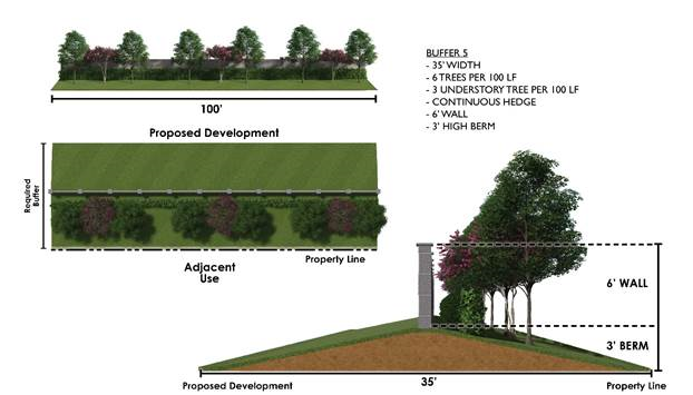
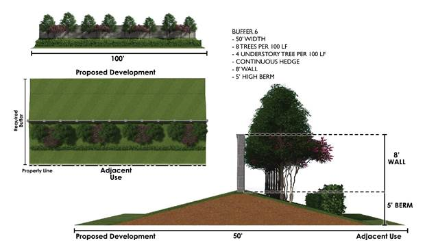
F.
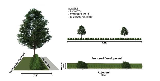
Perimeter Buffer Types. The following images show an example of buffer types defined in Table 4.2.
1.
Perimeter Buffer Type 1
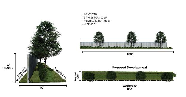
2.
Perimeter Buffer Type 2
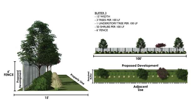
3.
Perimeter Buffer Type 3
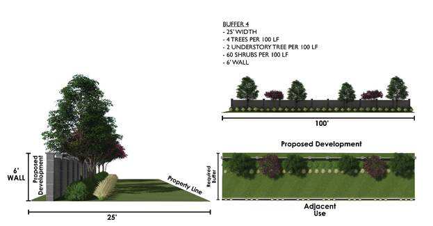
4.
Perimeter Buffer Type 4
5.
Perimeter Buffer Type 5
6.
Perimeter Buffer Type 6
(Ord. No. 2022-15, § 3(Exh. B), 7-12-22; Ord. No. 2023-05, § 2(Exh. A), 2-28-23)
4.3. - Perimeter Buffer Type Key
A.
Perimeter Buffer Type Key. Table 4.3 defines the minimum required buffer type when a zoning district abuts a different zoning district. Section 4.4: Additional Compatibility Mitigation, may require additional compatibility setback and buffer requirements for certain uses. Nothing in this section shall preclude an applicant from installing a buffer type exceeding the minimum standards. Table 4.3 defines the perimeter buffer types required when a traditional zoning district abuts a different traditional zoning district. Mixed Use District perimeter buffers shall be as required in Section 4.5: Mixed Use Considerations.
Table 4.3. Perimeter Buffer Type Key—Traditional Districts
B.
Perimeter Buffer along Public Roads/Rights-of-Way. Where there is an intervening roadway or right-of-way in excess of 50 feet, a minimum Perimeter Buffer Type 2 shall be required for all new development. The Planning Commission may increase the buffer type based on the proposed use(s) and/or roadway types and width.
(Ord. No. 2022-15, § 3(Exh. B), 7-12-22; Ord. No. 2023-12, § 2(Exh. A), 5-23-23)
4.4. - Additional Compatibility Mitigation
A.
Potential Incompatibilities. Potential incompatibilities between zoning districts shall be mitigated through techniques including, but not limited to:
1.
Providing open space, perimeter buffers, landscaping and berms.
2.
Screening of sources of light, noise, mechanical equipment, refuse areas, delivery and storage areas.
3.
Locating road access to minimize adverse impacts.
4.
Adjusting building setbacks to transition between different uses.
5.
Applying step-down or tiered building heights to transition between different uses.
6.
Lowering density or intensity of land uses to transition between different uses.
B.
Special Considerations. This section provides a tool to guide decision-makers in review of compatibility for unique circumstances and development types and where there are requests to modify development standards. These instances include: rezoning to planned districts; granting of conditional uses; granting of height exceptions; properties subject to the JPA/ILSBA; or developing property adjacent to properties having Sarasota County zoning designations. In these instances, the application of additional mitigation techniques may be deemed necessary to ensure compatibility of the proposed development with surrounding properties. Additional mitigation standards include, but are not limited to:
1.
Lowering density and intensity;
2.
Increasing building setbacks;
3.
Adjusting building step-backs (see Section 4.4.B. below);
4.
Requiring tiered buildings;
5.
Adjusting onsite improvements to mitigate lighting, noise, mechanical equipment, refuse and delivery and storage areas;
6.
Adjusting road and driveway locations; and
7.
Increasing buffer types and/or elements of the buffer type.
C.
Building Step-back. A building step-back is an architectural design element applied to the upper stories of a development. It is a wall or façade that is recessed to allow for more daylight to reach the street level and create a more open, inviting pedestrian environment. Step-backs reduce the scale of a building, increasing views of surrounding areas, and emphasize the ground floor of a structure to allow increased emphasis on pedestrian considerations. Step-backs may be required for stories or features above a certain permitted height within a zoning district per that district's development standards table and may be used as an additional compatibility mitigation technique per this section. The extent and width of a step-back shall be approved by the decision-making body responsible for compatibility review.
Figure 4.4 Step-back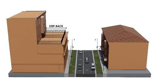
(Ord. No. 2022-15, § 3(Exh. B), 7-12-22)
4.5. - Mixed Use Considerations
A.
Perimeter of Mixed Use Districts. The buffer types identified in Table 4.5 shall be used when a Mixed Use District abuts a traditional district. When one Mixed Use District abuts another Mixed Use District, no buffer is required. If a roadway is between one of the Mixed Use Districts identified in Section 2 of this LDC and a traditional district, a right-of-way buffer is not required. Recognizing that the creation of Mixed Use Districts through this Code affects existing development and lot layouts in these districts, design alternatives may be requested.
Table 4.5. Mixed Use Districts Buffer Type
(Ord. No. 2022-15, § 3(Exh. B), 7-12-22)