
Billings City Zoning Code
ARTICLE 27
900.- EBURD
Sec. 27-901.- East Billings Urban Revitalization District.
A.
Purpose. The purpose of the East Billings Urban Revitalization District (EBURD) zoning districts and requirements is to provide standards for development as called for in the East Billings Urban Revitalization District Master Plan, adopted by the city in July 2009. The zoning districts are intended to allow existing uses to continue while integrating new mixed use and residential development appropriately with form-based regulations.
This code will be reviewed and modified as needed on an annual basis by the Billings Industrial Revitalization District, Inc. and the city.
B.
EBURD zoning districts. The areas and boundaries of the districts listed below are hereby established to scale as shown on the map entitled Billings Urban Zoning Jurisdiction, available at the city offices.
1.
EBURD RSV: Rail Spur Village District. The Rail Spur Village District is intended to create a walkable neighborhood focused on residential uses with associated green spaces and commercial businesses with the appropriate form.
2.
EBURD RSVMS: Rail Spur Village Main Streets District. The Rail Spur Village Main Streets include the extension of the Montana Avenue into the EBURD as well as the North 20th Street corridor from Montana Avenue to 6th Avenue North. This district is intended to create continuous, walkable, shopping and dining corridors including residential and office uses.
3.
EBURD CW: Central Works District. The Central Works District is intended to allow a flexible mix of uses, including commercial and light industrial uses.
4.
EBURD 13th: North 13th Street Main Street District. The North 13th Street Main Street is intended to provide a walkable, shopping and dining corridor including office and residential adjacent to the Central Works and Industrial Sanctuary districts, while allowing appropriate craftsman industrial and commercial businesses.
5.
EBURD IS: Industrial Sanctuary District. The Industrial Sanctuary District is intended to allow a wide mix of industrial businesses within the area with limited form requirements.
C.
Sustainable development measures.
1.
Generally. The following sustainable development measures process shall be addressed by all developments in the EBURD districts.
(a)
Requirements. The applicant shall achieve no less than five (5) total points from any combination of the following sustainable development measures. No partial points will be accepted.
(b)
Documentation. The applicant shall submit supporting documentation detailing how the development will achieve the measure in practice, on the site where it is proposed.
(c)
Review and approval. Documentation on which measures and total number of points the applicant will achieve shall be indicated on the building permit application submitted to the city for review and approval.
2.
Certified green buildings measure (3 points).
(a)
Action. Certify a new construction building or building undergoing major renovations through a green building rating system requiring review by an independent, third-party certifying body and approved by the zoning coordinator.
(b)
Value. This measure earns the applicant three (3) points.
(c)
Documentation. Required documentation includes registration of the project with the system, payment of all applicable fees for the rating system, and a draft scorecard showing the achieved credits or points.
3.
Building energy efficiency measure (2 points).
(a)
Action.
(1)
New construction buildings. Newly constructed buildings must demonstrate an average ten (10) percent improvement over the energy code currently in effect in the city.
(2)
Major renovation. Building must demonstrate an average five (5) percent improvement over ANSI/ASHRAE/IESNA Standard 90.1-2007.
(b)
Value. This measure earns the applicant two (2) points.
(c)
Documentation. Required documentation includes an energy model demonstrating that the building(s) will achieve the proposed improvements.
4.
Building Water Efficiency Measure (2 points).
(a)
Action. Indoor water use in new buildings and major renovations must be an average twenty (20) percent less than in baseline buildings. Utilize the baseline water usage for fixtures per the Energy Policy Act of 1992 and subsequent rulings by the United States Department of Energy or a similar method approved by the zoning coordinator.
(b)
Value. This measure earns the applicant two (2) points.
(c)
Documentation. Required documentation includes cut sheets for all water fixtures.
5.
Water-efficient landscaping measure (2 points).
(a)
Action. Reduce potable water used for landscape by utilizing all xeriscape plant materials and providing no permanent irrigation system or using only captured rainwater with an irrigation system.
(b)
Value. This measure earns the applicant two (2) points.
(c)
Documentation. Required documentation includes a landscape and irrigation plan, illustrating the system.
6.
Renewable energy sources measure (2 points).
(a)
Action. Incorporate renewable energy generation on-site with production capacity of at least five (5) percent of the building's annual electric and thermal energy, established through an accepted building energy performance simulation tool.
(1)
The following renewable energy generation sources are applicable:
a.
Solar thermal or photovoltaics.
b.
Wind.
c.
Geothermal.
(b)
Value. This measure earns the applicant two (2) points.
(c)
Documentation. Required documentation includes specifications and construction details for the installation of the system.
7.
Green roof measure (2 points).
(a)
Action. Install a vegetated roof for at least fifty (50) percent of building roof area.
(b)
Value. This measure earns the applicant two (2) points.
(c)
Documentation. Required documentation includes roof construction plans with drainage and planting details.
8.
Heat island reduction measure (2 points).
(a)
Action. Use any combination of the following strategies for thirty-five (35) percent of all on-site, non-roof hardscape areas, including sidewalks, plazas, courtyards, parking lots, parking structures, and driveways.
(1)
Tree canopy cover. Coverage of the surface at shade tree maturity in 15 years.
(2)
Solar reflective paving and roofing with a SRI (solar reflectance index) of at least twenty-nine (29).
(b)
Value. This measure earns the applicant two (2) points.
(c)
Documentation. Required documentation includes plans and specifications for installation of the strategy.
9.
Pervious pavement measure (2 points).
(a)
Action. Install an open grid or pervious pavement system that is at least forty (40) percent pervious on eighty (80) percent of all hardscape surface areas, including sidewalks, plazas, courtyards, parking lots, and driveways.
(b)
Value. This measure earns the applicant two (2) points.
(c)
Documentation. Required documentation includes plans and specifications for installation of the strategy.
10.
Enhanced bicycle amenities measure (1 point).
(a)
Action. Inclusion of two (2) of the following:
(1)
Lockable enclosed bicycle storage. Provide one secure, enclosed bicycle storage space for ten (10) percent of planned employee occupancy.
(2)
Employee shower facilities. Provide at least one shower facility and one per one hundred fifty (150) employees.
(3)
Increased bicycle parking spaces. Provide bicycle racks at a rate of one per five thousand (5,000) square feet of gross building area, with no fewer than four (4) bicycle spaces per building.
(b)
Value. This measure earns the applicant one point.
(c)
Documentation. Required documentation includes site and/or building plans locating the measures included.
(Ord. No. 21-5748, § 3(Exh. A), 1-25-21; Ord. No. 24-5885, § 3, 6-10-24)
Sec. 27-902. - Introduction to frontage type requirements.
The frontage types detailed in section 27-904 outline the required building forms for new construction and renovated structures within the EBURD.
A.
Applicability. The frontage type standards shall be applied to all new construction and exterior renovation of existing structures. Refer to article 27-1100, Proportionate compliance, for more information on the continuation of nonconforming structures.
B.
General requirements. All frontage types must meet the following requirements:
1.
Zoning districts. Each frontage type shall be constructed only within its designated districts (refer to Table 27-900-1, Permitted Frontage Types by Districts). Permitted frontage types in each zoning district defines which frontage types are permitted in which zoning districts.
2.
Uses. Each frontage type can house a variety of uses depending on the district in which it is located. Refer to article 27-1000, EBURD uses for general uses permitted per district. Some frontage types have additional limitations on permitted uses.
3.
No other frontage types. All buildings constructed must meet the requirements of one of the frontage types permitted within the zoning district of the lot.
4.
Permanent structures. All buildings constructed shall be permanent construction without a chassis, hitch, or wheels, or other features that would make the structure mobile, unless otherwise noted.
5.
Accessory structures.
(a)
Attached accessory structures are considered part of the principal structure.
(b)
Detached accessory structures are permitted per each frontage type and shall comply with all setbacks except the following:
(1)
Detached accessory structures are not permitted in the front yard.
(2)
Detached accessory structures shall be located behind the principal structure in the street-side yard.
(3)
Detached accessory structures shall not exceed the height of the principal structure and in no case shall be taller than two and one-half (2½) stories.
Table 27-900-1. Permitted Frontage Types.
(Ord. No. 21-5748, § 3(Exh. A), 1-25-21)
Sec. 27-903. - Entrance types.
Entrance type standards apply to the ground story and visible basement of front facades of all frontage types as defined in this section. Refer to section 27-904, Frontage types.
A.
General provisions. The following provisions apply to all entrance types:
1.
Intent. To guide the design of the ground story of all buildings to relate appropriately to pedestrians on the street. Treatment of other portions of the building facades is detailed in each frontage type standard (refer to subsections 27-904.A through 27-904.H).
2.
Applicability. The entire ground story street-facing facade(s) of all buildings shall meet the requirements of at least one of the permitted entrance types, unless otherwise stated.
3.
Measuring transparency. Refer to subsection 27-1802.D for information on measuring building transparency.
4.
Visible basements. Visible basements, permitted by entrance type, are optional. The visible basement shall be a maximum of one-half (½) the height of the tallest story.
5.
Storefront entrance type (Refer to Figure 27-903(1)). The storefront entrance type is a highly transparent ground story treatment designed to serve primarily as the display area and primary entrance for retail or service uses.
(a)
Transparency. Minimum transparency is required per frontage type.
(b)
Elevation. Storefront elevation shall be between zero and one foot above sidewalk.
(c)
Visible basement. A visible basement is not permitted.
(d)
Horizontal facade division. Horizontally define the ground story facade from the upper stories.
(e)
Entrance. All entries shall be recessed from the front facade closest to the street.
(1)
Recess shall be a minimum of three (3) feet and a maximum of eight (8) feet deep, measured from the portion of the front facade closest to the street.
(2)
When the recess falls behind the front build-to zone, the recess shall be no wider than eight (8) feet.
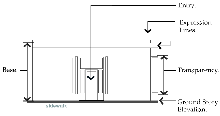
Fig. 27-903(1). Storefront Entrance Type.
6.
Arcade entrance type (Refer to Figure 27-903(2)). An arcade entrance type is a covered pedestrian walkway within the recess of a ground story.
(a)
Arcade. An open-air public walkway is required from the face of the building recessed into the building a minimum of eight (8) and a maximum of fifteen (15) feet.
(b)
Recessed or interior facade. Storefront entrance type is required on the recessed ground story facade.
(c)
Column spacing. Columns shall be spaced between ten (10) feet and twelve (12) feet on center.
(d)
Column width. Columns shall be a minimum of one (1) foot eight (8) inches and a maximum two (2) feet four (4) inches in width.
(e)
Arcade opening. Opening shall not be flush with interior arcade ceiling and may be arched or straight.
(f)
Horizontal facade division. Horizontally define the ground story facade from the upper stories.
(g)
Visible basement. A visible basement is not permitted.
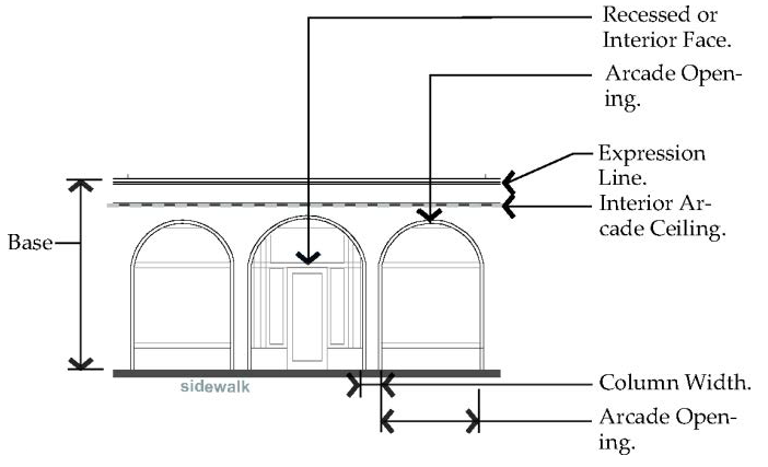
Fig. 27-903(2). Arcade Entrance.
7.
Stoop entrance type (Refer to Figure 27-903(3)).
(a)
A stoop is an unroofed, open platform.
(b)
Transparency. Minimum transparency is required per frontage type.
(c)
Stoop size. Stoops shall be a minimum of three (3) feet deep and six (6) feet wide.
(d)
Elevation. Stoop elevation shall be located a maximum of two (2) feet six (6) inches above the sidewalk without visible basement and a maximum of four (4) feet six (6) inches above the sidewalk with a visible basement.
(e)
Visible basement. A visible basement is permitted and shall be separated from the ground story by an expression line.
(f)
Entrance. All entries shall be located off a stoop.
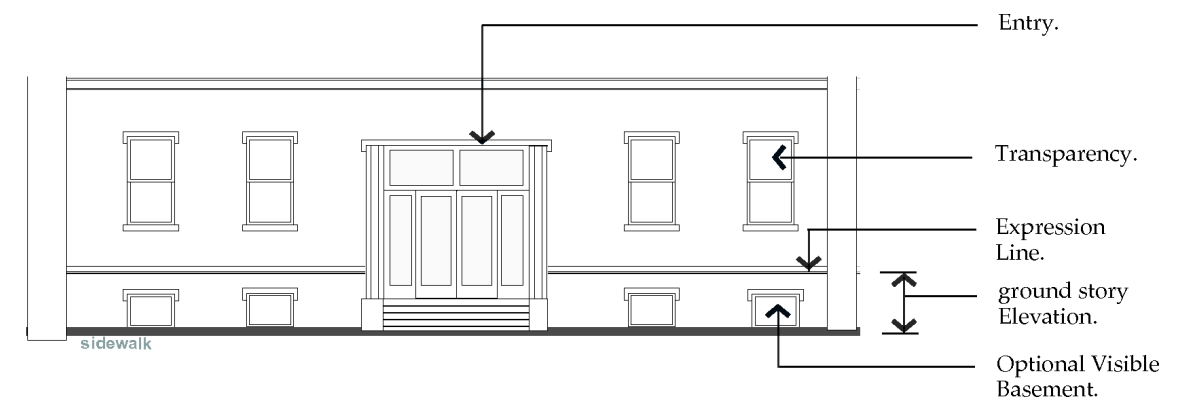
Fig. 27-903(3). Stoop Entrance Type.
8.
Porch entrance type (Refer to Figure 27-903(4)). A porch is a raised, roofed platform that may or may not be enclosed on all sides.
(a)
Transparency.
(1)
Minimum transparency per frontage type is required.
(2)
If enclosed, a minimum of forty (40) percent of the enclosed porch shall be comprised of highly transparent, low reflectance windows.
(b)
Porch size. The porch shall be a minimum of five (5) feet deep and eight (8) feet wide.
(c)
Elevation. Porch elevation shall be located a maximum of two (2) feet six (6) inches above the sidewalk without a visible basement and a maximum of four (4) feet six (6) inches above the sidewalk with a visible basement.
(d)
Visible basement. A visible basement is permitted.
(e)
Height. Porch may be two (2) stories to provide a balcony on the second floor.
(f)
Entrance. All entries shall be located off a porch.
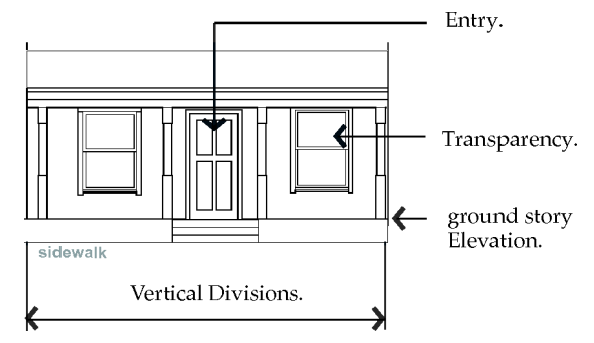
Fig. 27-903(4). Porch Cap.
B.
Street facade materials. The following applies to all facades visible from any street on all frontage types with the exception of the open frontage type:
1.
Permitted facade materials. Building materials that are permitted include durable, natural materials such as clay or terracotta tiles, stone, brick, stucco, concrete, and metal. Cast stone is permitted. Painted or stained wood, and burnished and/or split face colored concrete masonry units are permitted as no more than thirty-five (35) percent of street facing facade.
2.
Permitted upper story facade materials. In addition to the permitted facade materials defined in subsection 27-903.B.1, exterior insulation and finishing systems (EIFS) is permitted on upper stories.
3.
Materials to avoid. Building materials that are discouraged on any street facing facade include imitation materials intended to look like natural materials; sheet materials intended to look like units; and residential grade windows and doors on all frontage types except the yard frontage.
4.
Prohibited materials on street facing facades. Building materials that are not permitted on building facades that are visible from any street include bricks more than 3⅝-inch in height, and untreated wood.
(Ord. No. 21-5748, § 3(Exh. A), 1-25-21)
Sec. 27-904. - Frontage types.
A.
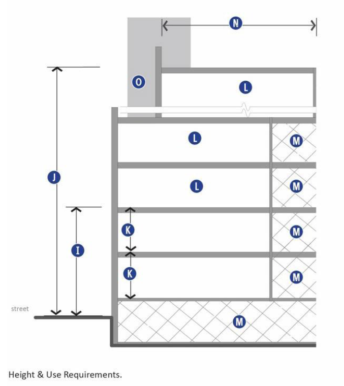
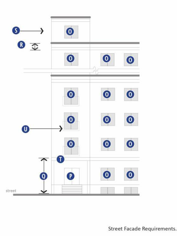
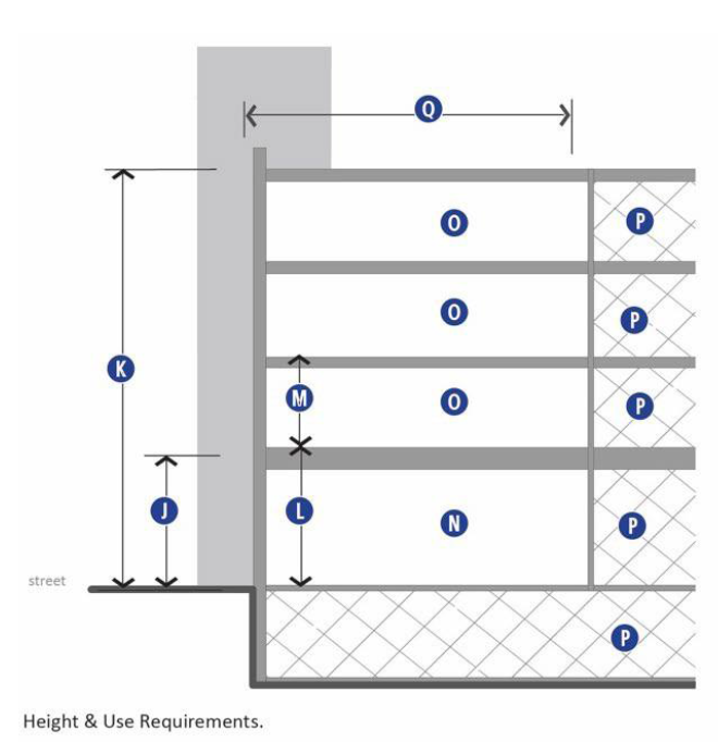
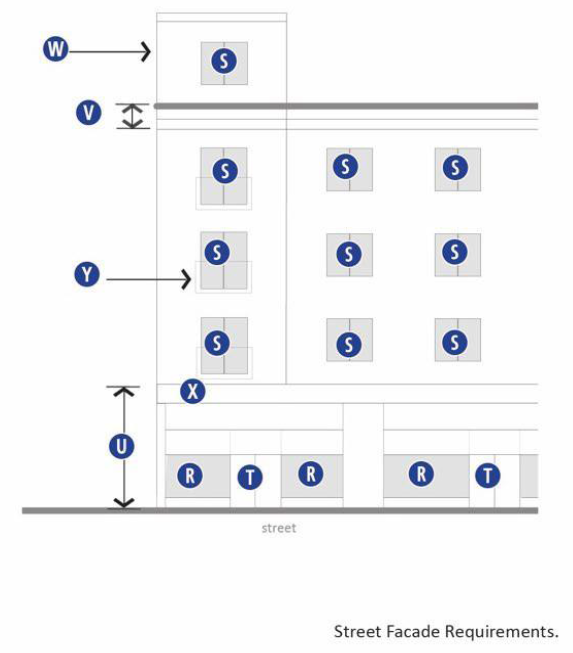
Frontage type: Yard frontage. The following regulations apply to yard frontage type as allowed in EBURD districts per Table 27-900-1. Refer to sections 27-902 and 27-903, for general regulations applicable to all frontage types and Table 27-900-2, below, for regulations specific to this frontage type, keyed to illustrations in Figures 27-904(1)—(3). See article 27-1800 for definitions and information on how to measure the following regulations:
Table 27-900-2. Yard Frontage Regulations.
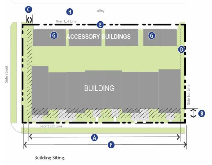
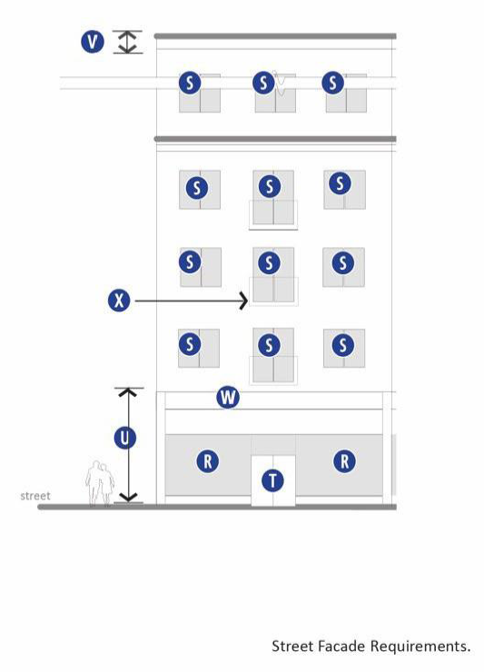
Figure 27-904(1). Building Siting.
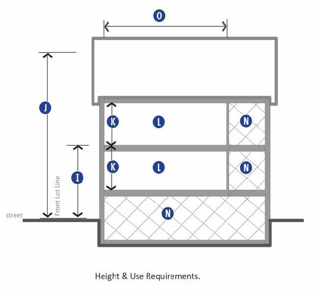 | 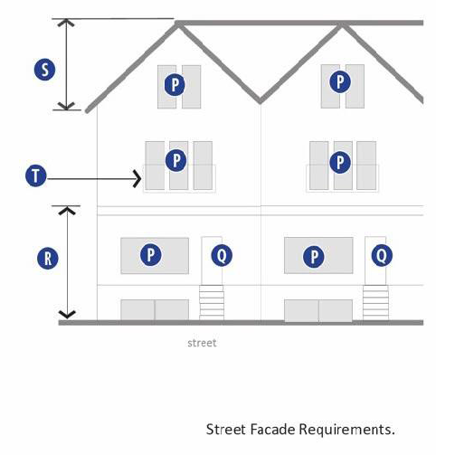 |
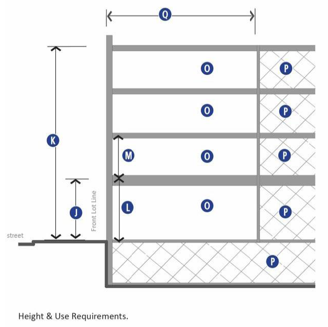
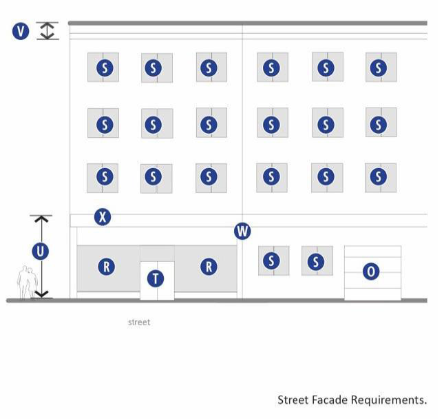
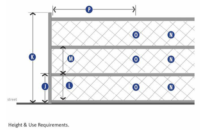
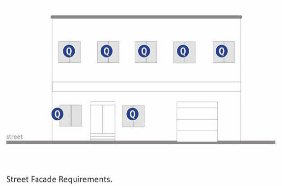
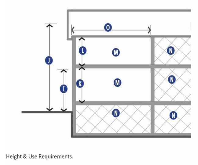
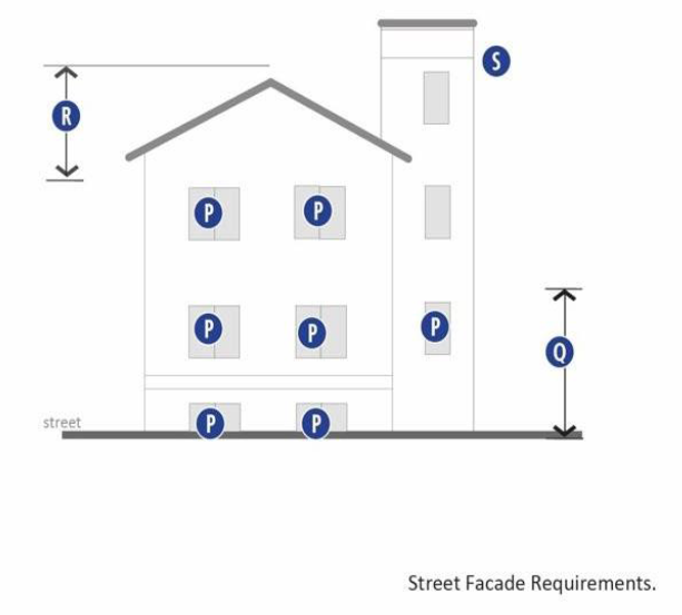
| Figure 27-904(2). Height & Use Requirements. | Figure 27-904(3). Street Facade Requirements. |
B.
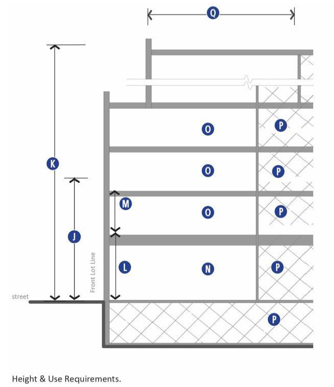
Frontage type: General stoop frontage. The following regulations apply to general stoop frontage type as allowed in EBURD districts per Table 27-900-1. Refer to sections 27-902 and 27-903, for general regulations applicable to all frontage types and Table 27-900-3, below, for regulations specific to this frontage type, keyed to illustrations in Figure 27-904(4)—(6). See article 27-1800 for definitions and information on how to measure the following regulations.
Table 27-900-3. General Stoop Frontage Regulations.
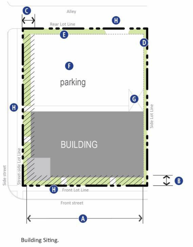
Figure 27-904(4). Building Siting.
 |  |
| Figure 27-904(5). Height & Use Requirements. | Figure 27-904(6). Street Facade Requirements. |
C.
Frontage type: Storefront frontage. The following regulations apply to storefront frontage type as allowed in EBURD districts per Table 27-900-1. Refer to sections 27-902 and 27-903, for general regulations applicable to all frontage types and Table 27-900-4, below, for regulations specific to this frontage type, keyed to illustrations in Figures 27-904(7)—(9). See article 27-1800 for definitions and information on how to measure the following regulations.
Table 27-900-4. Storefront Frontage Regulations.
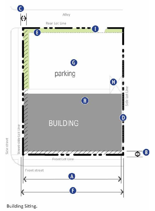
Figure 27-904(7). Building Siting.
 |  |
| Figure 27-904(8). Height & Use Requirements. | Figure 27-904(9). Street Facade Requirements. |
D.
Frontage type: Limited bay frontage. The following regulations apply to limited bay frontage type as allowed in EBURD districts per Table 27-900-1. Refer to sections 27-902 and 27-903, for general regulations applicable to all frontage types and Table 27-900-5, below, for regulations specific to this frontage type, keyed to illustrations in Figures 27-904(10)—(12). See article 27-1800 for definitions and information on how to measure the following regulations:
Table 27-900-5. Limited Bay Frontage Regulations.
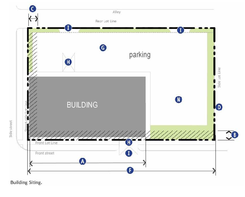
Figure 27-904(10). Building Siting.
 |  |
| Figure 27-904(11). Height & Use Requirements. | Figure 27-904(12). Street Facade Requirements. |
E.
Frontage type: Commerce frontage. The following regulations apply to commerce frontage type as allowed in EBURD districts per Table 27-900-1. Refer to sections 27-902 and 27-903, for general regulations applicable to all frontage types and Table 27-900-6, below, for regulations specific to this frontage type, keyed to illustrations in Figures 27-904(13)—(15). See article 27-1800 for definitions and information on how to measure the following regulations:
Table 27-900-6. Commerce Frontage Regulations.
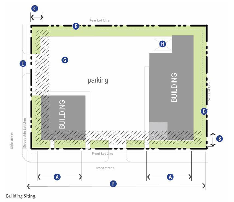
Figure 27-904(13). Building Siting.
 |  |
| Figure 27-904(14). Height & Use Requirements. | Figure 27-904(15). Street Facade Requirements. |
F.
Frontage type: Open frontage. The following regulations apply to open frontage type as allowed in EBURD districts per Table 27-900-1. Refer to sections 27-902 and 27-903, for general regulations applicable to all frontage types and Table 27-900-7, below, for regulations specific to this frontage type, keyed to illustrations in Figure 27-904(16)—(18). See article 27-1800 for definitions and information on how to measure the following regulations:
Table 27-900-7. Open Frontage Regulations.
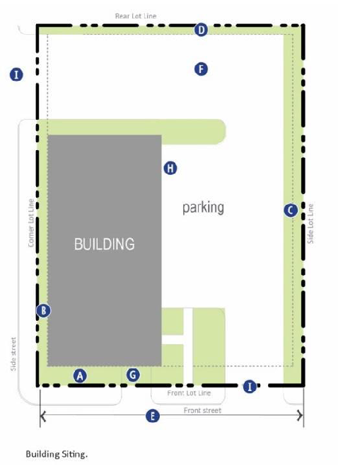
Figure 27-904(16). Building Siting.
 |  |
| Figure 27-904(17). Height & Use Requirements. | Figure 27-904(18). Street Facade Requirements. |
G.
Frontage type: Civic frontage. The following regulations apply to civic frontage type as allowed in EBURD districts per Table 27-900-1. Refer to sections 27-902 and 27-903, for general regulations applicable to all frontage types and Table 27-900-8, below, for regulations specific to this frontage type, keyed to illustrations in Figures 27-904(19)—(21). See article 27-1800 for definitions and information on how to measure the following regulations:
Table 27-900-8. Civic Frontage Regulations.
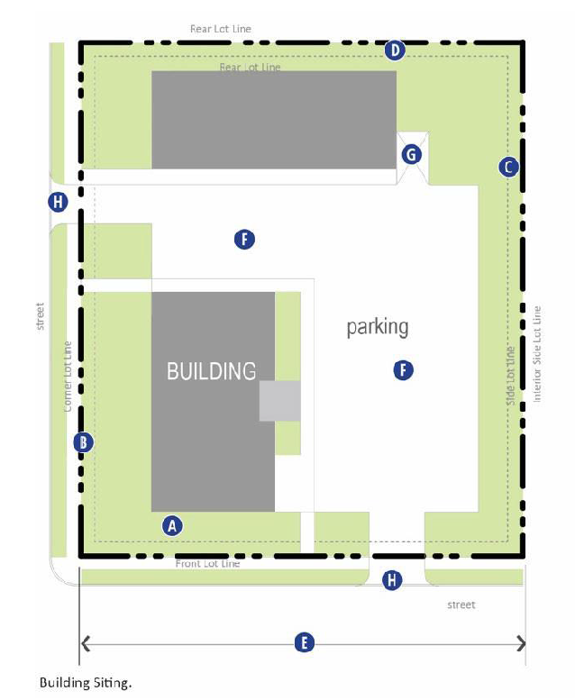
Figure 27-904(19). Building Siting.
 |  |
| Figure 27-904(20). Height & Use Requirements. | Figure 27-904(21). Street Facade Requirements. |
H.
Frontage type: Commercial outdoor site. The following regulations apply to commercial outdoor site frontage type as allowed in EBURD districts per Table 27-900-1. Refer to sections 27-902 and 27-903 for general regulations applicable to all frontage types and Table 27-900-9, below, for regulations specific to this frontage type, keyed to illustrations in Figure 27-904(22). See article 27-1800 for definitions and information on how to measure the following regulations.
Table 27-900-9. Commercial Outdoor Site Frontage Regulations.
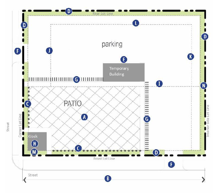
Figure 27-904(22). Building Siting.
(Ord. No. 21-5748, § 3(Exh. A), 1-25-21)
Sec. 27-905. - Landscaping standards.
A.
General compliance.
1.
Application of this section to existing uses shall occur with the following developments:
(a)
The expansion of more than thirty (30) percent of the surface area of an existing parking lot or loading facility, including any associated driveways.
(b)
Alteration to an existing principal or accessory structure that results in a change of fifteen (15) percent or more in the structure's gross floor area.
(c)
When compliance is triggered for existing parking lots, landscape improvements shall take precedence over parking requirements.
B.
General requirements. Refer to article 27-1200 for all landscape requirements, including but not limited to the approval process, materials, installation, and maintenance. However, the EBURD specific standards in this section 27-905, supersede the requirements of sections 27-1204 through 27-1206.
C.
Landscape area requirements. These standards apply to all development except single family residential.
1.
Tree requirements. One (1) evergreen, ornamental or shade tree is required for every two thousand five hundred (2,500) square feet of landscape area.
(a)
Existing tree canopy may be utilized to meet this requirement.
(b)
If less than two thousand five hundred (2,500) square feet of landscape area exists, tree plantings are not required.
2.
Fences and walls. These standards apply to all lots in all EBURD districts. Fences and walls must adhere to the following standards:
(a)
Height. The maximum height of any fence or wall shall be six (6) feet measured from the ground at the base of the fence or wall to the top of the fence boards or wall.
(1)
Posts, decorative columns, light fixtures, or other decorative details are permitted to exceed the height limit by up to two (2) feet.
(2)
Fences over four (4) feet in height are not permitted in the front yard.
(3)
In the central works [district], the maximum height of any fence or wall shall be eight (8) feet.
(4)
In the industrial sanctuary [district], height limits do not apply.
(b)
Location. All fences and walls must be located within a lot's lot lines.
(c)
Materials.
(1)
Permitted materials. Brick; stone; cast stone; wood; painted, matte finish vinyl; wood composites; or steel are permitted fence and wall materials.
(2)
Prohibited materials. Barbed wire, chain link, exposed cinder or concrete block, metal mesh, and razor wire and single wire fences and wall are prohibited with the following exceptions:
a.
In the industrial sanctuary districts, chain link, razor wire, and barbed wire fencing are permitted. Sharp fencing must be located eight (8) feet above grade.
(d)
Opacity. Fences along the front yard or front lot line shall have a maximum opacity of fifty (50) percent.
3.
Buffers. Landscape buffers are required according to the provisions in this section with the following exceptions:
(1)
Shared driveways. Buffers shall not be required along a lot line where a curb cut or aisle is shared between two (2) adjoining lots.
(2)
Points of access. Buffering is not required at driveways or other points of access to a lot.
D.
Frontage buffer requirements (Refer to Figure 27-905(1)).
Table 27-900-10. Frontage Buffer.
| (1) Intent & Applicability | ||
| Intent | To lessen the visual impact of vehicular areas & outdoor storage visible from the street | |
|
General
Applicability | Applies to Frontage Types where a vehicular area or outdoor storage is located adjacent to a Right-of-Way | |
| Exceptions | Vehicular areas along alleys, except when a residential district is located across the alley; Single and two family residences | |
| (2) Buffer Depth & Location1 | ||
| Depth | 7' | |
| Location on the Site | Between street facing Lot line and parking area 2 | |
| (3) Buffer Landscape Requirements | ||
|
Uses &
Materials | Uses and materials other than those indicated are prohibited in the buffer | |
| Shade Trees |
Medium or large shade tree required at least every 40'; Locate on
the street side of the fence; Spacing should alternate with street trees | |
| Hedge | Required continuous hedge on street side of fence, between shade trees & in front of vehicular areas | |
|
Hedge
Composition | Individual shrubs with a minimum width of 24", spaced no more than 36" on center | |
|
Existing
Vegetation | May be credited toward buffer area | |
| (4) Fence | ||
| Location | 2' from back of curb of vehicular area | |
| Materials | Steel or painted, matte finish PVC; Masonry columns (maximum width 2'6") and base (maximum 18" height) permitted | |
|
Minimum
Height | 3' | |
|
Maximum
Height | 4' | |
| Colors | Black, gray, or dark green | |
| Opacity | Minimum 20%; Maximum 60% | |
| Gate/Opening | One gate permitted per street frontage; Opening width maximum 6' | |
| Notes: | ||
| 1 This screening requirement does not prohibit the installation of or provision for openings necessary for allowable access drives and walkways connecting to the public sidewalk. | ||
| 2 In front, corner, and rear yards on a through lot, when the parking area is located adjacent to any building on the lot, the buffer must be located so that it aligns with or is behind the face of the adjacent building back to the vehicular area. The area between the buffer and the lot line must be landscaped. | ||
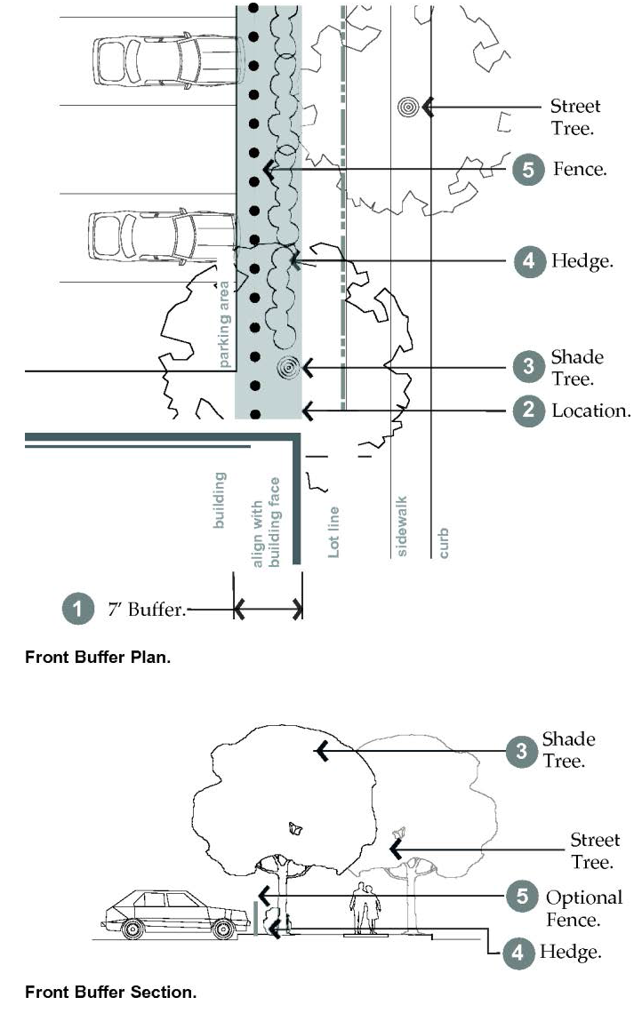
Figure 27-905(1). Frontage Buffer Plan and Section.
E.
Interior parking lot landscaping requirements (Refer to Figure 27-905(2)).
Table 27-900-11. Interior Parking Lot Landscaping.
| (1) Intent & Applicability | ||
| Intent | To provide shade, minimize paving & associated storm water runoff, & improve the aesthetic look of parking lots | |
|
General
Applicability | All open-air, off-street parking lots 1 | |
| Other Internal Parking Lot Areas | Internal areas not dedicated to parking or drives shall be landscaped with a minimum of one medium or large shade tree for the first 150 square feet and one medium or large shade tree for every 650' thereafter | |
|
Existing
Vegetation | Existing vegetation may be credited toward these requirements | |
| (2) Landscape Island Requirements | ||
| Required Island Locations | Terminal ends 2 of free standing rows or bays of parking; after every ninth parking space for rows of parking greater than 10 spaces in length | |
|
Minimum
Width | 5'; Islands less than 15' must utilize structural soil under any paved surface within a tree's recommended permeable surface area requirement; Islands under 9' must install an aeration system and utilize permeable pavement | |
| Required Trees Within Islands | Minimum of 1 medium or large shade tree per island | |
| (3) Tree Requirements | ||
| Requirements per Parking Space 3 | Each parking space must be located within 50' of a tree planted within parking lot interior; and no more than 8 continuous parking spaces in a row are permitted without a landscape island | |
| Minimum of 1 shade tree must be planted within parking lot interior or within 4' of parking lot's edge for every 3 parking spaces | ||
| Tree Shade | Within 20 years of tree installation, 30% of the interior of the parking lot must be shaded by tree canopy | |
| Notes: | ||
| 1 Parking lot interior is defined as the area dedicated to parking on a given parcel as measured from the farthest edge of pavement to opposing farthest edge of pavement. | ||
| 2 Freestanding rows or bays of parking are those not abutting the parking lot perimeter or building face, and may have a single or double row of parking. | ||
| 3 Trees within a designated buffer area may not be utilized to meet these requirements. Trees and landscaping located outside of the parking lot interior, including in the side and rear buffer or frontage buffer, may not be applied to this requirement. | ||
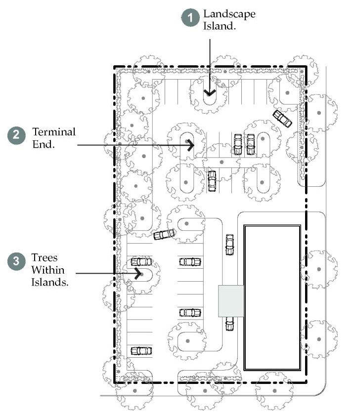
Figure 27-905(2). Interior Parking Lot Landscape.
Table 27-900-12. Estimated Canopy and Height at Maturity.
F.
Side and rear buffer requirements (Refer to Figure 27-905(3)).
Table 27-900-13. Side and Rear Buffer.
| A. Intent & Applicability | ||
| Intent | To minimize the impact that one building may have on a neighboring district and to provide a transition between districts | |
| General | Applies to all directly adjoining properties as outlined in Table 27-900-14 1 | |
| B. Required Landscape Screen | ||
| Size | 5' landscape screen in addition to any other buffer landscaping | |
| Location | Directly adjacent to the Rear or Side Lot line per Fig. 27-905.3 | |
| Hedge | Continuous double row of shrubs required between shade trees | |
|
Hedge
Composition | Double row of individual shrubs with a minimum width of 24", spaced no more than 36" on center; Mature height in one year of 24" | |
|
Hedge
Frequency | Minimum of 15 shrubs per 100' of Lot line is required | |
| Shade Trees | At least 1 medium or large shade tree per every 40' within the buffer | |
|
Uses and
Materials | Uses and materials other than those indicated are prohibited within the buffer | |
|
Existing
Vegetation | May be credited toward buffer area | |
| C. Required Fence | ||
|
Permitted
Materials | Steel or painted, matte finish PVC for semi-opaque; Wood or masonry for opaque. Chain link not permitted. | |
|
Minimum
Height | 6' | |
|
Maximum
Height | 8' | |
| Colors | If steel: black, gray, or dark green | |
| Opacity | Option 1: Semi-Opaque 20%—60% opacity, hedge required; Option 2: Opaque fence, no hedge required | |
| Notes: | ||
| 1 Zoning coordinator may reduce width of buffer, width of landscape screen, or location of landscape screen based on existing landscaping and similarity between uses. | ||
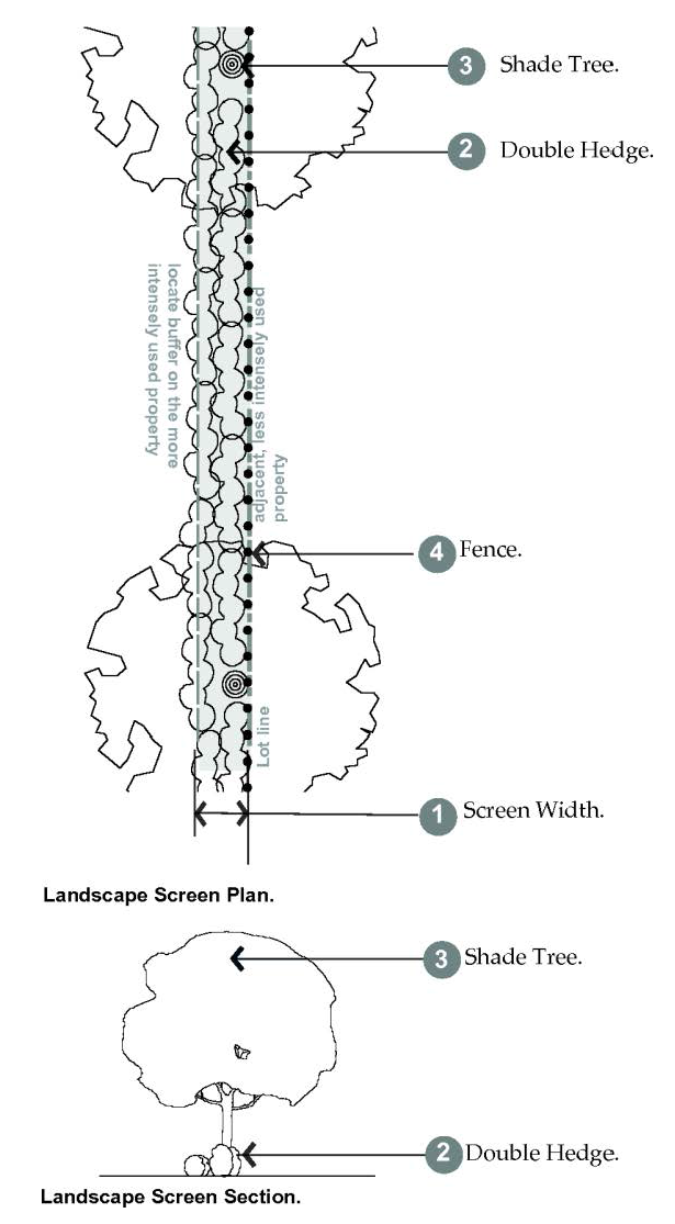
Figure 27-905(3). Landscape Screen within Side & Rear Buffer.
Table 27-900-14. Side and Rear Buffer Requirements by District.
G.
Commercial patio frontage (Refer to Figure 27-905(4)).
Table 27-900-15. Commercial Patio Frontage.
| (1) Intent & Applicability | ||
| Intent | To provide a buffer between outdoor sales uses and street activity | |
|
General
Applicability | Applies to Commercial Outdoor Site Frontage Type only (refer to section 27-904) | |
| (2) Frontage Location | ||
|
Minimum
Depth | 7' | |
| Location on the Site | Between 5' and 20' from Front and Corner Side Lot line adjacent to patio/display area | |
| (3) Buffer Landscape Requirements1 | ||
| Shade Trees | Medium or large shade tree required at least every 40'; Spacing should alternate with street trees 2 | |
| Shrubs | Required continuous shrubs on street side of fence | |
|
Hedge
Composition | Individual shrubs with a minimum width and height of 12", spaced no more than 24" on center | |
|
Existing
Vegetation | May be credited toward buffer area | |
| (4) Required Fence | ||
| Materials | Steel or painted, matte finish PVC; Masonry base or columns permitted | |
|
Minimum
Height | 18" | |
|
Maximum
Height | 4' | |
| Colors | Black, gray, or dark green for steel or PVC | |
| Opacity 3 | Minimum 30 percent; Maximum 60% | |
| Gate/Opening | Two gates permitted per street frontage; Opening width maximum 6' | |
| Notes: | ||
| 1 This screening requirement does not prohibit the installation of or provision for openings necessary for allowable access drives and walkways connecting to the public sidewalk. | ||
| 2 Exception: Trees for Automobile Sales Use may be spaced 90' on center. | ||
| 3 Fence may be solid if 30" or less in height. | ||
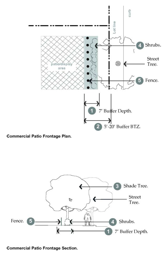
Figure 27-905(4). Commercial Patio Frontage Plan and Section.
(Ord. No. 21-5748, § 3(Exh. A), 1-25-21; Ord. No. 25-5907, § 3, 4-14-25)
Sec. 27-906. - Street type standards.
A.
General requirements.
1.
Intent. The standards outlined in this section are intended to:
(a)
Create complete streets that address all modes of travel, including pedestrian traffic, bicycle traffic, transit, and vehicular traffic.
(b)
Address all features of the street right-of-way, including sidewalks, parkways, traffic lanes, bicycle lanes, and medians.
(c)
Continue the existing logical and comprehensible system of streets that result in a simple, consistent and understandable pattern of blocks and lots.
(d)
Provide adequate access to all lots for vehicles and pedestrians.
(e)
Create streets that are appropriate for their contexts in residential, commercial, or mixed-use districts and are designed to encourage travel at appropriate volumes and speeds.
2.
Applicability. The standards in this section apply to all vehicular rights-of-way within the EBURD.
3.
General requirements. All proposed streets, landscape or furnishings zones, and sidewalks shall be located in dedicated vehicular rights-of-way as required by this article.
(a)
Street types. All new vehicular rights-of-way shall match one of the street types; refer to subsections 27-906.D.1 through 27-906.D.5, whether publicly dedicated or privately held.
(b)
Public use. All streets shall be available for public use at all times. Gated streets and streets posted as private are not permitted.
(c)
Master plans. Refer to any adopted city master plans for additional information, such as the current bikeway and trail master plan.
(d)
Street construction specifications. All construction in the right-of-way shall follow specifications defined by the department of public works, engineering division.
B.
General street type standards.
1.
Street types. Street types defined in this section outline acceptable street configurations. New streets should be designed using the principles and characteristics defined by each street type. The department of public works, engineering division, or the Montana Department of Transportation, as applicable (refer to Figures 27-906.5a and 5b), may require additional right-of-way, pavement width, or additional street elements depending on specific site characteristics.
2.
Summary street type tables. Table 27-900-16, summarizes the requirements of each street type.
3.
Graphics. The graphics provided, illustrating each street type, are samples of recommendations and illustrate only one possible configuration of that street type. By applying the guidelines outlined and working with the department of public works, engineering division, other configurations can be determined acceptable.
4.
Typical street elements. Typical elements of a vehicular right-of-way are divided into the vehicular and pedestrian
realm. Each street type detailed in this article outlines which facilities are applicable.
Refer to Figure 27-906(1), typical right-of-way
elements.
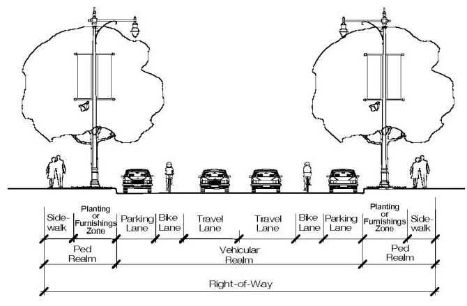
Figure 27-906(1). Typical Right-of-Way Elements.
(a)
Vehicular realm. The vehicular realm is comprised of the travel lanes, bicycle lanes, and parking lanes.
(b)
Pedestrian realm. The pedestrian realm is comprised of pedestrian facilities, such as sidewalk, path/trail, or off-street bicycle path. A buffer area that serves to buffer pedestrians or bicyclists from the movements of higher speed vehicles in the vehicular realm shall consist of one of the following:
(1)
Landscape zone. A landscape area between the back of curb to the sidewalk in which street trees, storm water swales, lighting, and signage may be located. Typically used adjacent to residential ground floor uses.
(2)
Furnishings zone. A hardscape area that extends from the sidewalk to the back of curb, in which street trees, street furniture, lighting, and signage may be located. Typically used adjacent to commercial or office ground floor uses.
(c)
Bicycle facilities. The following types of bicycle accommodations are permitted in the vehicular realm. Refer to Figure 27-906(2).
(1)
Dedicated bicycle lane. Dedicated bicycle lanes are striped lanes on the outside of the outermost travel lanes that are designated for only bicycle use. This lane occurs on both sides of the street and shall be four (4) to five (5) feet wide.
(2)
Designated shared lane. A designated shared lane is a lane that is shared between vehicles and bicycles. This lane is typically wider than a standard vehicular lane, minimum thirteen (13) feet, in order to accommodate both types of users, and includes a painted bicycle marker combined with a double arrow (known as a "sharrow"). This improvement occurs on both directions.
(3)
Shared lane. A shared lane refers to a street that does not have bicycle lanes or a designated shared lane, but the speed and configuration of the street is such that bicycles could comfortably share lanes with traffic.
(4)
Cycle track. A cycle track is a separate on-road bike facility that is typically adjacent to, but physically separated from, vehicular traffic and parking by a barrier.
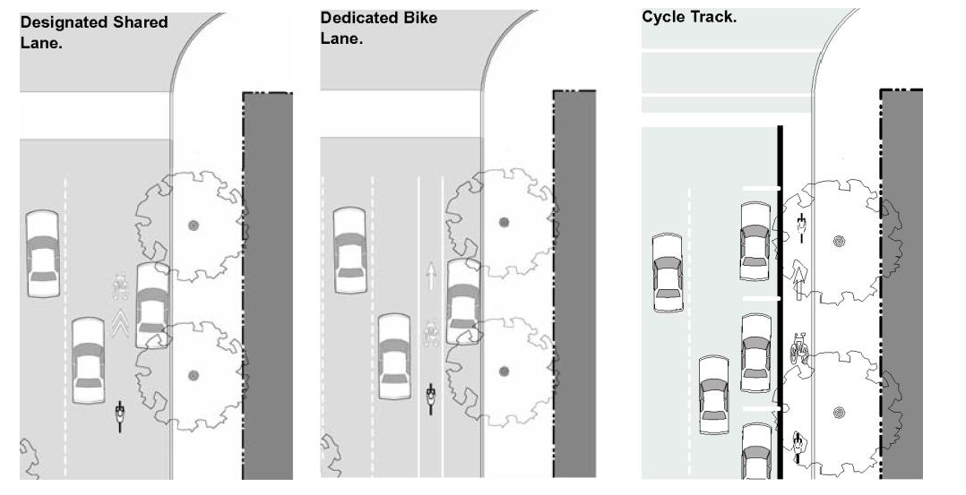
Figure 27-906(2). On-Street Bicycle Facilities.
(d)
Vehicular on-street parking. On-street parking, as permitted on designated street types, must meet the following requirements:
(1)
Parallel and back-in diagonal parking is permitted on designated street types.
(2)
Vehicular on-street parking space dimensions.
a.
The appropriate stall depth for back-in diagonal on-street parking spaces are defined for each street type (refer to subsections 27-906.D.2 through 27-906.D.5).
b.
The width of an on-street parking space shall be measured from the center of a stripe, minimum eight and one-half (8½) feet, unless otherwise noted.
c.
Back-in diagonal on-street parking shall be at sixty (60) degrees.
(e)
Storm water management. Incorporation of storm water management best practices into the right-of-way design is encouraged, such as incorporating drainage swales into the landscape zone or permeable paving in the parking lane. Refer to Figure 27-906(3) and the city's storm water management manual.
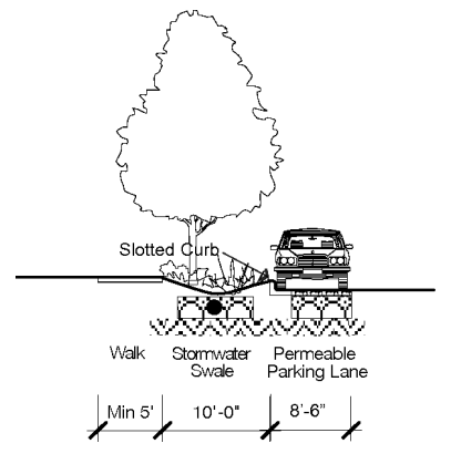
Figure 27-906(3). Storm Water Management Best Practices Incorporated in the Right-of-Way.
(f)
Street trees. Street trees are required along all street frontages; refer to subsection 27-5. Street trees shall be located in either a landscape zone (within a planting bed or lawn) or a furnishings zone (in trees wells with grate as required).
C.
General street layout requirements. The following standards apply to new streets or newly platted vehicular rights-of-way:
1.
Interconnected street pattern. The network of streets shall form an interconnected pattern with multiple intersections with the following features:
(a)
Street network. The arrangement of streets shall provide for the continuation of existing streets from adjoining areas into new subdivisions or developments.
(b)
Block pattern. To the maximum extent possible, the existing block pattern shall be continued and reinforced, and the following encouraged:
(1)
Avoid the closure of existing streets so as to maintain the existing network.
(2)
As railway tracks are abandoned or larger sites redevelop, new streets should be introduced to extend the existing pattern, incorporating the existing block sizes.
(c)
Bulb shaped cul-de-sac streets are not permitted.
(d)
New dead ends should be avoided.
2.
Intersection design. The following section outlines the regulations for developing and reconstructing intersections:
(a)
Applicability. The regulations outlined in this section shall apply to all planned intersections and may serve as guidance for reconfiguration of existing intersections.
(b)
Curb radii. The following curb radii shall be utilized unless otherwise authorized by the department of public works, engineering division:
(1)
Intersections should be designed for actual turning radius of the typical design vehicle as opposed to the maximum design vehicle. Small curb radii at intersections shorten pedestrian crossing distances and reduce vehicle turning speeds, thereby balancing the ease of travel of the vehicles and pedestrians. Refer to Figure 27-906(4).
(2)
Alley, neighborhood, and connector streets. At the intersection of any street with an alley, neighborhood, or a connector street, the following curb radii shall be utilized.
a.
With on-street parking on both streets and no bulb-out, a five-foot radius is required.
b.
Without on-street parking, a 15-foot radius is required.
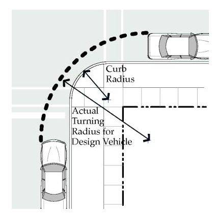
Figure 27-906(4).
Actual Right Turn Radius with On-Street Parking.
(3)
Avenues and boulevards. At the intersection of avenues with either another avenue or a boulevard, the following curb radii shall be utilized.
a.
With on-street parking on both streets and no bulb-out, a 12-foot radius is required.
b.
Without on-street parking on either streets, a 25-foot radius is required.
(4)
Larger radius. When the design vehicle requires a larger curb radius, a larger radius may be utilized with approval of the public works, engineering division.
(c)
Crosswalks. Crosswalks shall be required at all intersections involving Montana Avenue, N 20th Street, and N 13th Street.
(1)
Dimensions. Crosswalks shall be minimum eight (8) feet in width, measured from mid-stripe to mid-stripe, per city standards.
(2)
Markings. Crosswalks shall be appropriately indicated on the finished street surface with painted markings and/or textured or colored pavement.
(3)
Crossing distances. To encourage pedestrian activity, typical crosswalks shall not extend over thirty-eight (38) feet without a landscape median, bulbouts, and/or other pedestrian refuge to mitigate the effects of vehicular traffic on crossing and increase pedestrian safety and comfort.
(4)
Bulb-outs. To shorten pedestrian crossing distances, bulb-outs should be utilized at all intersections, unless otherwise required by the department of public works or the Montana Department of Transportation as applicable (refer to Figure 27-906(5b) for state maintained routes).
a.
The depth of the bulb-out shall match the utilized on-street parking, either the width of the parallel space or the depth of the diagonal space.
b.
The radius of the bulb-out shall match the requirements for the intersection.
(d)
Accessible ramps and warning panels. Accessible ramps and warning panels, per the American Disabilities Act or any more stringent state requirement, are required where all sidewalks or trails terminate at a crosswalk or curb.
(1)
Ramp orientation. Ramps should be generally oriented perpendicular to traffic, requiring two (2) ramps per corner at intersecting streets.
3.
Maps of street types. Refer to the maps on the following pages:
(a)
Street type map. Refer to Figure 27-906(5a). To provide context for any future platted rights-of-way and guidance for future improvements to existing rights-of-way, existing streets within EBURD are mapped in accordance with the street types outlined in subsections 27-906.F through 27-906.J.
(b)
State maintained routes. For reference purposes only, a map of routes currently maintained by the state department of transportation is included. Refer to Figure 27-906(5b).
(c)
Primary street map. Refer to Figure 27-906(5c).
(1)
Primary streets are defined as the higher priority street at an intersection, designating the front property line as well as establishing the higher level of pedestrian orientation with limited sidewalk interruptions from driveways.
(2)
At the intersection of any two (2) streets, the street with the highest level designation is considered the primary street. For example, at the intersection of 2nd Avenue N and N 19th Street, N 19th Street is designated as Street 1, a higher priority street, and is therefore the primary street. The front property line of a building on this corner would be on N 19th Street.
(3)
When a corner is located at the intersection of two (2) streets of the same priority level, either street may be chosen as the primary street.
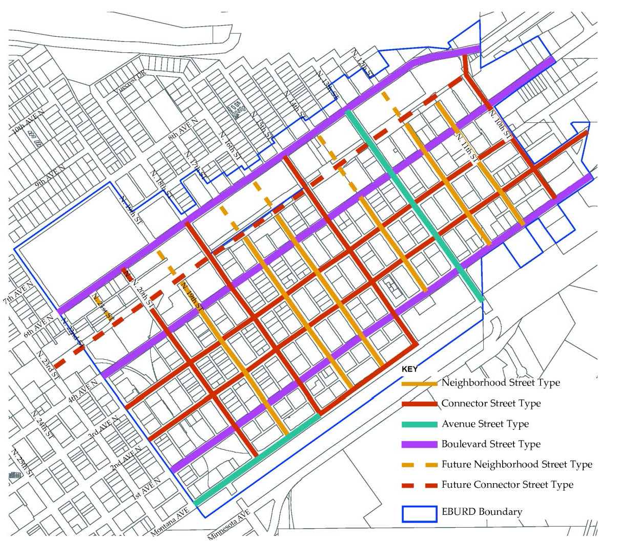
Figure 27-906.5a. Map of Street Types.
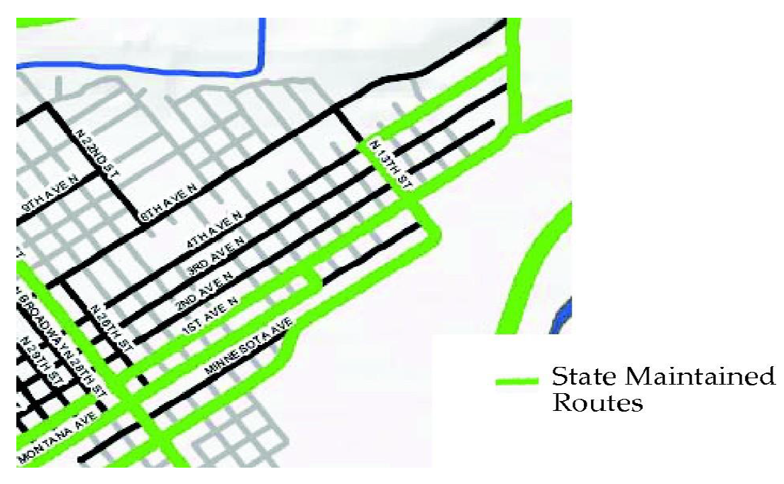
Figure 27-906(5b). Map of State Maintained Routes as of February 2012, for Reference
Only.
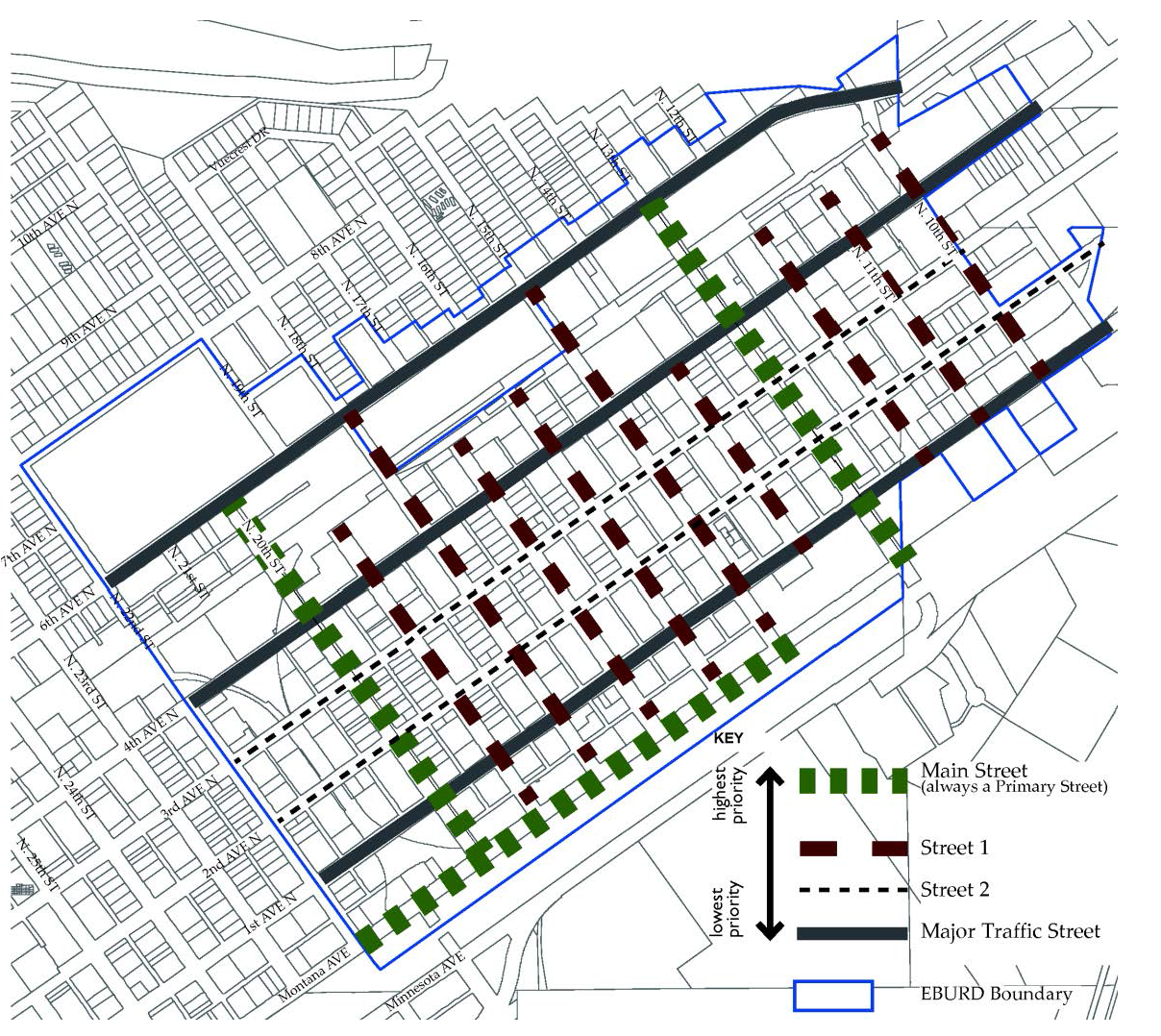
Figure 27-906(5c). Map of Street Priority.
4.
Street Type Summary Table. Refer to Table 27-900-16 for a summary table of all street types requirements defined in subsections 27-906.D through 27-906.H.
Table 27-900-16. Street Type Summary Table.
D.
Street types—Specifications.
1.
Alley.
(a)
Intent. The alley is a very low capacity drive located at the rear of parcels. From the alley, access to parking facilities, loading facilities, and service areas, such as refuse and utilities is possible without a curb cut or driveway interrupting a street type. Refer to the typical plan and section in Figure 27-906(6).
(b)
General requirements. Alleys shall be developed using the guidelines in Table 27-900-17. The department of public works, engineering division, may require additional right-of-way, pavement width, or street elements depending on specific site characteristics.
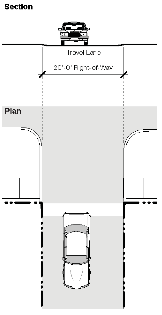
Figure 27-906(6). Typical Sample Alley.
Table 27-900-17. Alley Guidelines.
2.
Neighborhood Street.
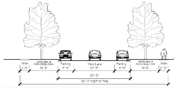
Figure 27-906(7a).
Alternative Sample Neighborhood Street.
(a)
Intent. The neighborhood street is a low capacity street designed for slow speeds with a standard right-of-way. It primarily serves those residences or businesses directly adjacent to it. Refer to the typical plan and section, Figure 906(7a).
(b)
General requirements. The neighborhood street shall be developed using the guidelines in Table 27-900-18. The department of public works, engineering division, may require additional right-of-way, pavement width, or street elements depending on specific site characteristics.
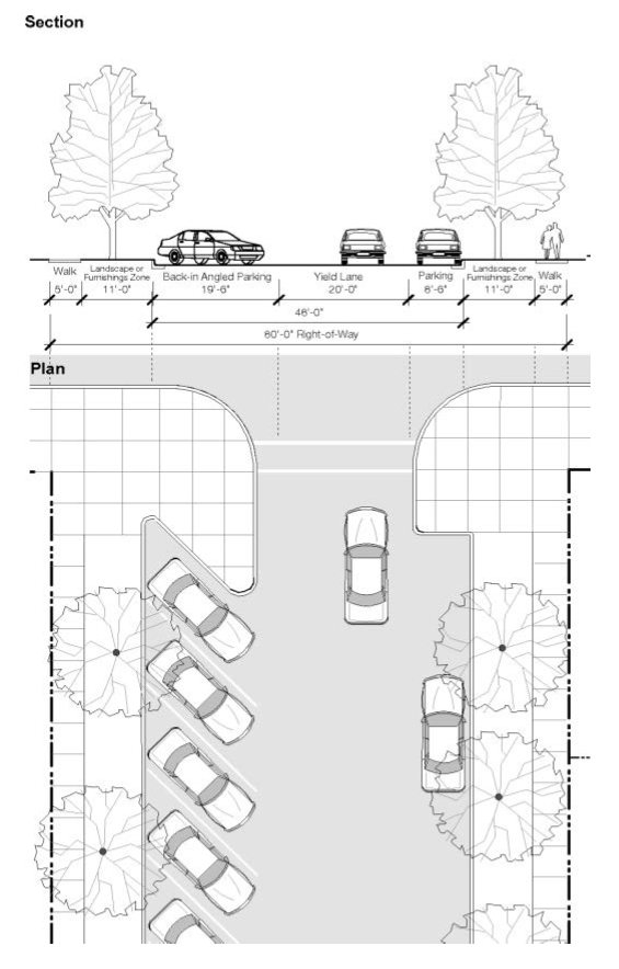
Figure 27-906(7b).
Typical Sample Neighborhood Street.
Table 27-900-18. Neighborhood Street Guidelines.
3.
Connector street.
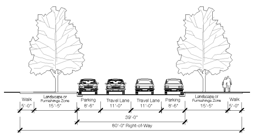
Figure 27-906(8b).
Alternative Sample Connector.
(a)
Intent. The connector street is a medium capacity street for slow speeds with a standard right-of-way. It primarily serves as a through street within the neighborhood and connects neighborhood streets to avenues or boulevards. Refer to the typical plan and section, Figure 27-906(8a).
(b)
General requirements. Connectors shall be developed using the guidelines in Table 27-900-19. The department of public works, engineering division, may require additional right-of-way, pavement width, or street elements depending on specific site characteristics.
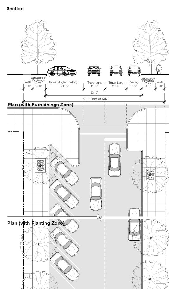
Figure 27-906(8a). Typical Sample Connector.
Table 27-900-19. Connector Guidelines.
4.
Avenue.
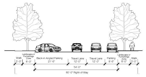
Figure 27-906(9b). Alternative Sample Avenue.
(a)
Intent. The avenue is a high capacity street for higher speeds with a wider right-of-way. It serves all types of development and provides crosstown connections. Refer to the typical plan and section in Figure 27-906(9a).
(b)
General requirements. Avenues shall be developed using the guidelines in Table 27-900-20. The department of public works, engineering division, or state department of transportation, may require additional right-of-way, pavement width, or street elements depending on specific site characteristics.
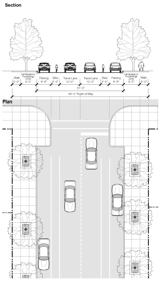
Figure 27-906(9a). Typical Sample Avenue.
Table 27-900-20. Avenue Guidelines.
5.
Boulevard.
(a)
Intent. The boulevard is a high capacity street for higher speeds with a wider right-of-way, one-way only in this case. It serves all types of development and provides crosstown connections. Refer to the typical plan and section, Figure 27-906(10a).
(b)
General requirements. Boulevards shall be developed using the guidelines in Table 27-900-21. The department of public works, engineering division, or state department of transportation, may require additional right-of-way, pavement width, or street elements depending on specific site characteristics.
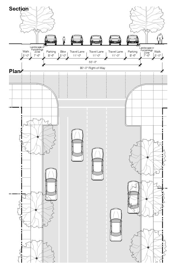
Figure 27-906(10a). Typical Sample One-Way Boulevard - 6th Ave. N & Portions of 1st
Ave. N.
Table 27-900-21. Boulevard Guidelines.
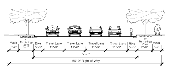
Figure 27-906(10b). Sample Two Way Boulevard.
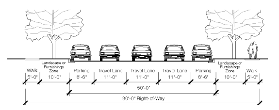
Figure 27-906(10c). Sample One-Way Boulevard.
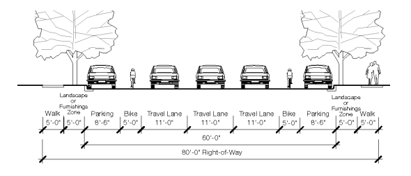
Figure 27-906(10d). Sample One-Way Boulevard - 4th Street.
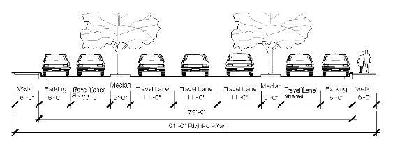
Figure 27-906(10e). Sample
One-Way Blvd. w/Access Rd.