
Fort Smith City Zoning Code
ARTICLE 27
600.- GENERAL DEVELOPMENT STANDARDS
Sec. 27-601.- Off-street parking and loading.
27-601-1
Approval procedure for off-street parking, loading and vehicle access.
A.
New construction or remodeling. No building permit for new construction, expansion or change in occupancy shall be approved until a parking plan has been reviewed and approved by the building official as a part of the building and site plan review process. No certificate of occupancy shall be issued until all off-street parking and loading facilities have been constructed or bonded according to the building permit.
B.
Plan and information required. As part of the application for a building permit for new construction, expansion or a change in occupancy of an existing structure the applicant shall submit a parking plan showing the number, location and size of all parking spaces. The applicant shall submit information necessary to demonstrate compliance with these regulations.
C.
Plans for paving of parking area. Plan for paving of all off-street parking areas, aisles, and access driveways, including detailed drainage plans, shall be reviewed and approved by the engineering department for compliance with this division.
D.
Permits required. All new parking lots and additions to existing parking lots shall require a building permit.
27-601-2
Parking and loading space requirements. Listed below are land uses which are included in this chapter. Each land use has a specific parking and loading standard which must be met. In certain cases where a land use has no specific standard determined in advance by these regulations, the director shall make a determination of need after review of the site plan.
27-601-2: Parking Standards Table
TABLE 27-601-2: PARKING STANDARDS TABLE
A.
Multifamily developments. The minimum number of parking spaces required for multifamily developments shall comply with Table 27-601-2.
(1)
Bicycle racks. One bicycle rack per 20 dwelling units shall be provided.
(2)
Compact spaces. A maximum of 20 percent of the total spaces may be compact spaces at a rate of one compact space for one automobile space. Compact spaces shall be identified as "Compact Only".
(3)
Motorcycle parking space. Up to ten percent of the required automobile parking spaces may be substituted with motorcycle parking at a rate of one motorcycle space for one automobile space.
(4)
Reduction. Multifamily developments may reduce the minimum number of required parking listed in Table 27-601-2 by 15 percent when properties are located within a radius of 1,320 feet of a transit stop.
B.
Commercial developments.
1.
There shall be a minimum and maximum number of parking spaces required for commercial uses. The parking standards for commercial developments shall comply with Table 27-601-2.
2.
The following standards apply to commercial development:
(a)
Motorcycle parking. One motorcycle parking space may be substituted for every 25 parking spaces.
(b)
Bicycle parking. One bicycle parking rack shall be provided per 20 automobile parking spaces.
(c)
Compact spaces. A maximum of 20 percent of the total spaces may be compact spaces. Compact spaces shall be identified as "Compact Only:
C.
Maximum parking calculation exceptions. For the purpose of calculating parking requirements, the following types of parking spaces shall not count against the maximum parking requirement:
1.
Accessible parking.
2.
Spaces with electrical vehicle charging stations, up to a maximum of two per 50 parking spaces.
D.
For mixed land uses, parking requirements will be tabulated separately for each land use within the development, using the list of specific standards or the tables above.
E.
Queuing space. Five queuing spaces shall be required per drive-up window.
(Ord. No. 105-22, § 1, 11-1-2022)
27-601-3
Bicycle parking requirements. The following standards shall apply:
A.
Commercial development. Commercial developments shall provide one bicycle parking rack per 20 automobile parking spaces.
B.
Multifamily development. Multifamily development shall provide one bicycle rack per 20 dwelling units.
C.
Bicycle racks shall be secured to a hard surface.
(Ord. No. 47-10, § 2, 10-5-2010; Ord. No. 105-22, § 1, 11-1-2022)
27-601-4
Loading facilities.
A.
Off-street loading space required. Every industrial, commercial, retail, wholesale, office, and/or civic building erected or expanded shall provide space for loading unloading of vehicles as identified in subsection 27-601-2. The number of off-street loading spaces required by this division shall be considered the minimum, and the developer shall evaluate the needs of the development to determine if they are greater than the minimum specified by this division.
B.
Number of off-street loading spaces required. The following table illustrates the number of required loading spaces required by land use category according to the floor area. Where a use will not require the loading space identified by this table, the applicant may request that the planning commission allow the loading space to be marked for additional parking. Loading space may not be eliminated from a site or incorporated into a building.
C.
Loading facility design criteria.
1.
Off-street loading spaces shall be oriented so that vehicles, regardless of size, can maneuver entirely within property lines. Property lines and street rights-of-way adjacent to maneuvering and loading areas to be protected by a six-foot fence, 18 inches tall welded, pipe barrier or other approved device.
2.
Site/development plan shall provide basic loading design elements including:
a.
Certified and dimensioned turning radii for size and types of vehicles utilizing docks regarding dock location, circulation on the site and ingress and egress from site.
b.
Site entrance and egress shall comply with driveway standards as per section 27-603 (access management).
c.
Description of drainage to prevent standing water in dock areas.
d.
Area and security lighting for dock area shall comply with section 27-602-5 (commercial and outdoor lighting).
e.
Description, location and detail of property line, structure and rights-of-way barriers.
D.
Loading zones. Off-street loading requirements shall not be required within any commercial downtown zoning district. However, the chief of police must approve any loading or unloading activity in any commercial downtown zoned area.
E.
Violations. Violations to this section will be subject to the enforcement procedures and penalties listed in these regulations.
27-601-5
Parking; purpose and intent. This section is designed to provide adequate parking and maneuvering facilities for all land uses in the city. The standards and procedures of this section are intended to ensure that each land use will have facilities that are functionally adequate for its purpose.
27-601-6
Off-street parking requirements.
A.
Permanent off-street parking in the amount specified in this section for any land use shall be provided when any new building is constructed or when any existing principal building is expanded.
B.
In addition, permanent off-street parking shall be required when property is changed from one land use to another or when a building is changed from one type of occupancy to another. Occupancy for this purpose is defined in the city's building code.
(Ord. No. 105-22, § 1, 11-1-2022)
27-601-7
Use of public right-of-way prohibited.
A.
No portion of any parking space or minimum required maneuvering area may make use of any part of a public street, right-of-way, alley or other public property.
B.
No public street, right-of-way or public property may be used to gain direct access to a parking space except that an alley can be used for maneuvering space to reach a parking space.
27-601-8
Exemption. Legally established land uses and structural uses, existing at the effective date of this ordinance, where minimum required parking is not provided, shall not be required to meet these minimum requirements until required in subsection 27-601-6.
27-601-9
Minimum standards, property owner responsibility. The standards in this section are minimum requirements. It shall be the responsibility of the property owner to certify at the time of application for a building permit that the development plan provides sufficient spaces and facilities necessary to ensure that no activity will take place on public rights-of-way or property not under the owner's control.
27-601-10
Ownership or control. The land on which the off-street parking or loading facility is located shall be owned or controlled by the same entity which owns and controls the land on which the principal use is located, or by a joint use agreement as defined in subsection 27-601-11B of this section.
27-601-11
Off-street parking standards.
A.
Remote parking permitted. If the off-street parking space required by this section cannot be reasonably provided on the same lot on which the principal use is located, space may be provided elsewhere if approved by the planning commission, but in any case the parking must be within 300 feet of the facility it serves.
B.
Joint parking facilities. The required parking spaces for any number of separate land uses may be combined in a joint parking facility under the following conditions:
a.
Shared parking. Separate facilities under separate ownership and control may use a common parking lot provided a legal and binding agreement such as a shared parking agreement is utilized which grants each of the separate facilities the right to use the common parking lot is filed with the circuit clerk. The agreement must grant each facility enough space in the common parking lot to meet the minimum parking requirements of the city. Parking required will be calculated according to the minimum parking standards in section 27-342 referring to common parking lots.
b.
Church and school parking lots. A facility located within 300 feet of the property line of a church or school may use the parking lot of the church or school to provide up to 25 percent of its required parking so long as the operating schedules of the facility and the church or school do not conflict. This also applies vice versa as:
i.
A church or school located within 300 feet of the property line of another facility may use the parking lot of that facility for up to 25 percent of its required parking so long as the operating schedules of the church or school and the facility do not conflict.
ii.
In either case, a document must be filed with the director showing that the operating schedules of the facilities involved do not conflict. At such time that the schedules do conflict, the separate facilities will be required to provide enough additional parking to meet the requirements of this chapter.
c.
Residential parking design. Single-family and duplex residential structures located on one lot may use a paved driveway to fulfill the minimum parking requirements of this section. The space for each automobile shall be a minimum of nine feet in width and 19 feet in length. The residential driveway shall conform to the driveway design requirements of chapter 22, article III.
27-601-12
Parking area construction standards.
A.
Paving. All portions of access driveways or public rights-of-way connected to paved streets for which the grade has been established must comply with chapter 22, article III (driveway approaches and curbs).
B.
Design. Off-street parking areas shall be designed to provide systematic and orderly circulation, traffic separation devices, and parking spaces in accordance with this article and with sound traffic engineering practices.
C.
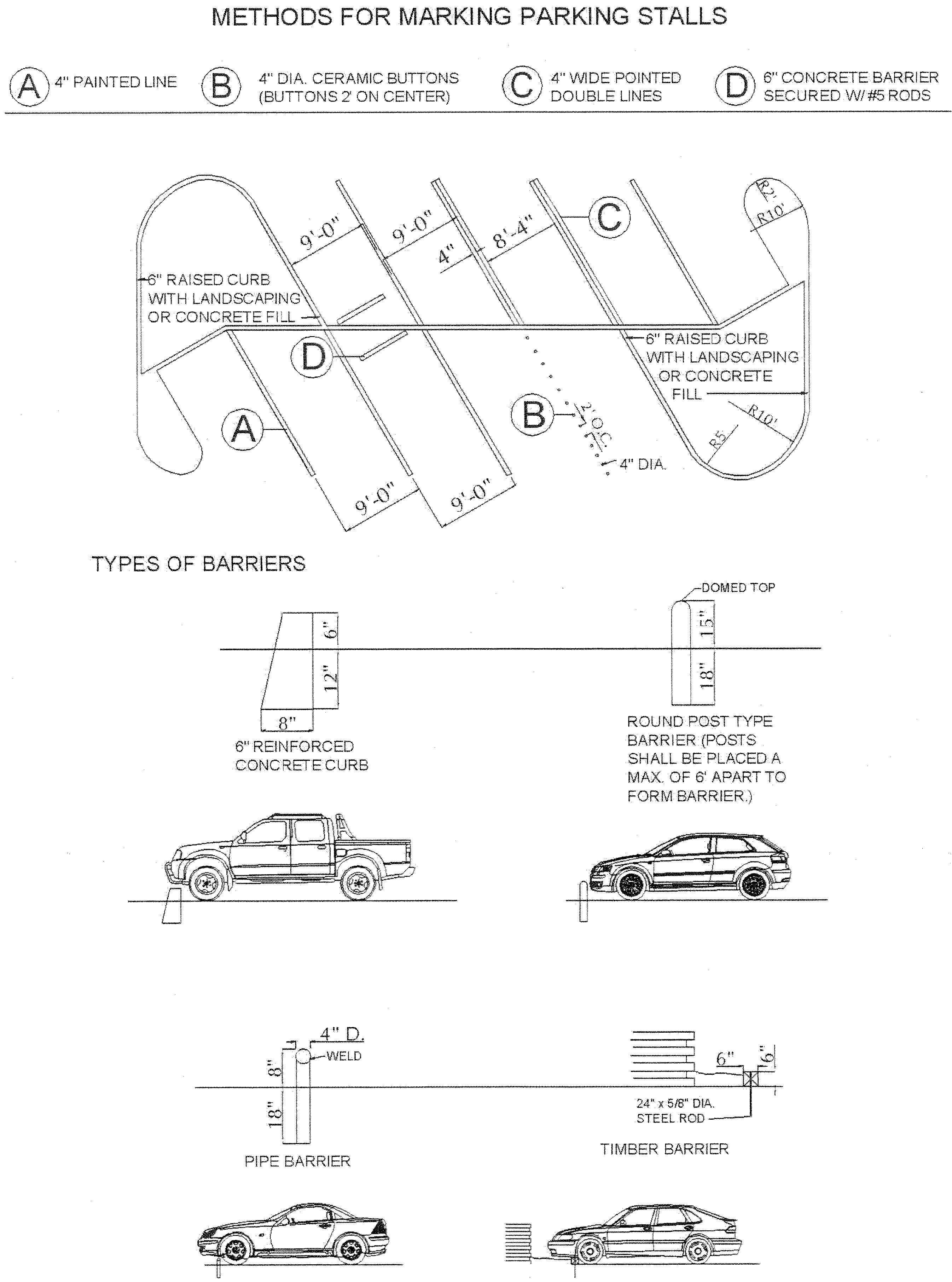
Separation from public right-of-way. All off-street parking and public right-of-way shall be separated by a six-inch-high concrete header curb, bumper or landscape timbers and shall be designed so that vehicles do not overhang public sidewalks, public rights-of-way or adjacent property.
D.
Lighting. Lighting illumination levels for off-street parking shall not create a hazard for traffic or be a nuisance to adjoining properties.
E.
Clearance.
a.
An eight-foot-high vertical clearance free of all obstructions is required for all portions of any off-street parking space, except when off-street parking spaces are provided in a parking structure, a residential garage or carport.
b.
No obstruction within or near the bounds of any required off-street parking space shall interfere with the normal use of the space.
27-601-13
Handicapped parking.
A.
The number of accessible spaces allocated will follow the guidelines set out in the city's building code and ICC/ANSI A117.1.
B.
Accessible parking spaces and accessible routes shall be designed according to the city's building code and ICC/ANSI A117.1.
27-601-14
Minimum parking design standards.
A.
Parking area design standards.
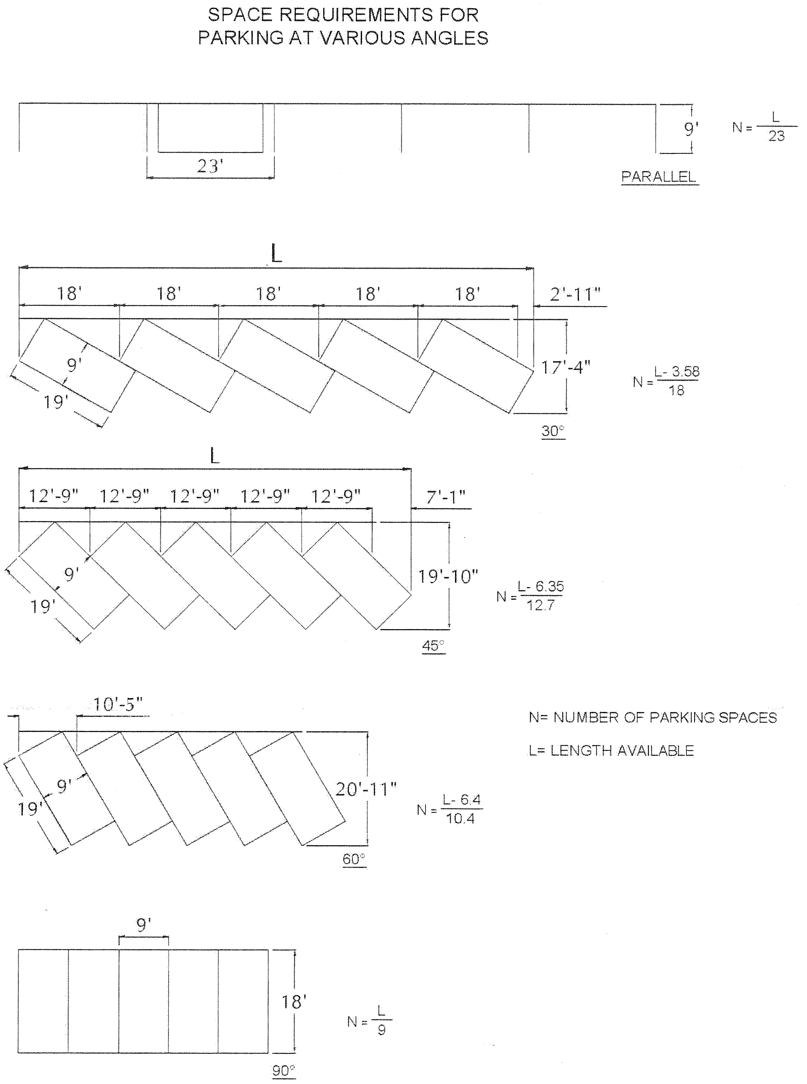
1.
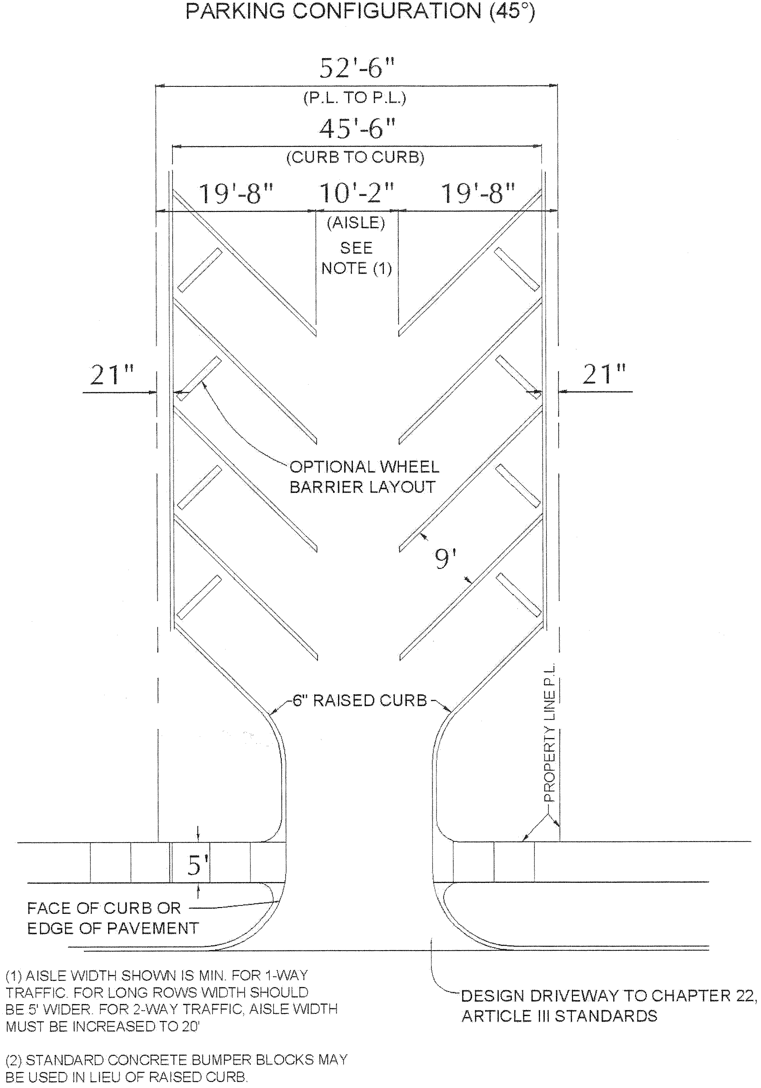
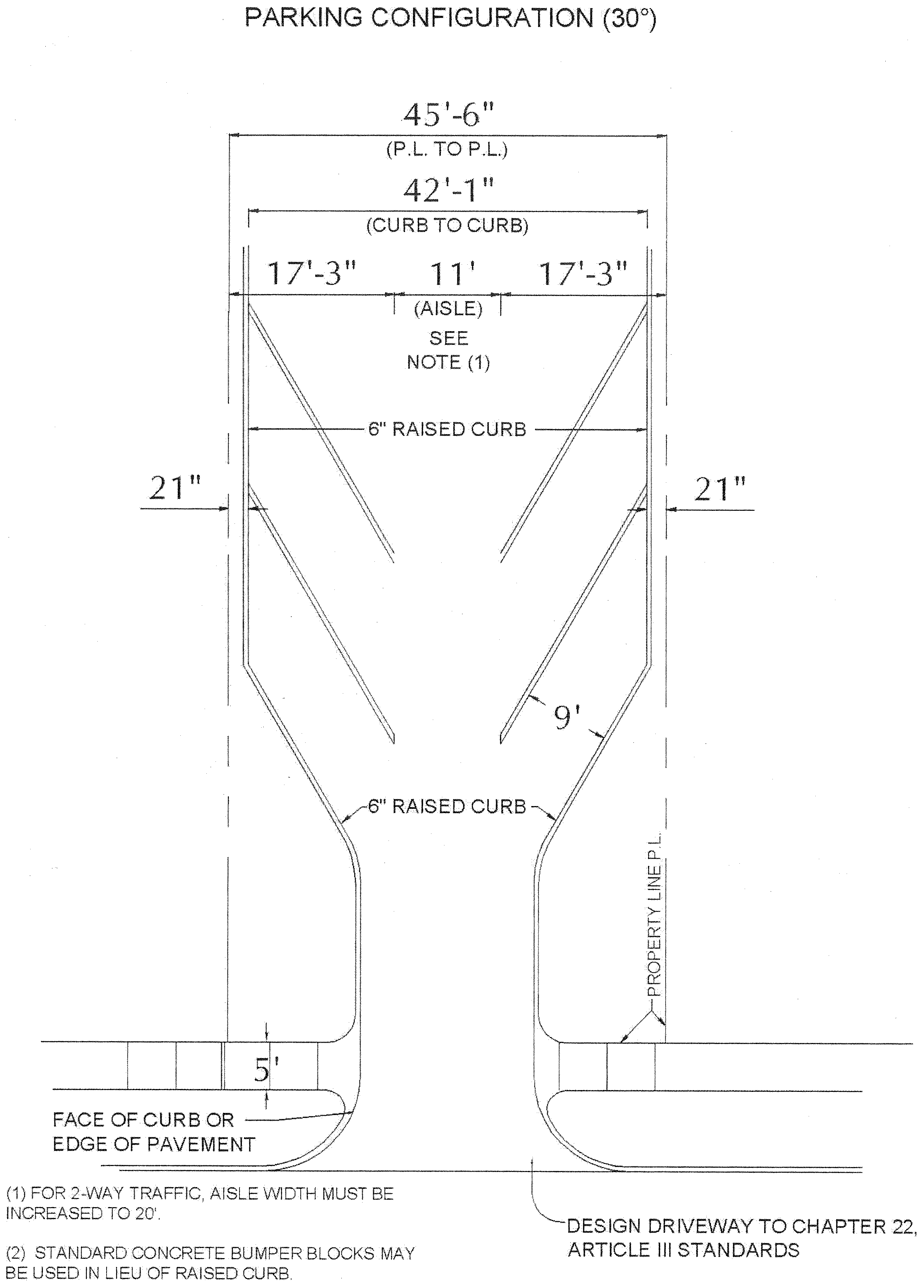
Basic design standards. The basic parking space dimension shall be a width of nine feet and a length of 18 feet. The following tables and diagrams establish the minimum design and dimension standards for parking areas.
2.
Alternative design standards. While the tables provide design standards for angles of zero degrees, 45 degrees, 60 degrees, 75 degrees and 90 degrees, the building official shall be permitted to approve an alternative design using different angles, provided the property owner submits such a design with calculations for parking spaces and aisles based upon the standards contained herein.
3.
Compact parking space dimensions. Eight-foot width—16-foot length. Compact spaces shall be identified as "Compact Only".
4.
Motorcycle parking space dimensions. Four-foot width—nine-foot length.
B.
Queuing space. Queuing spaces required for certain land uses in this chapter shall conform to the following standards:
C.
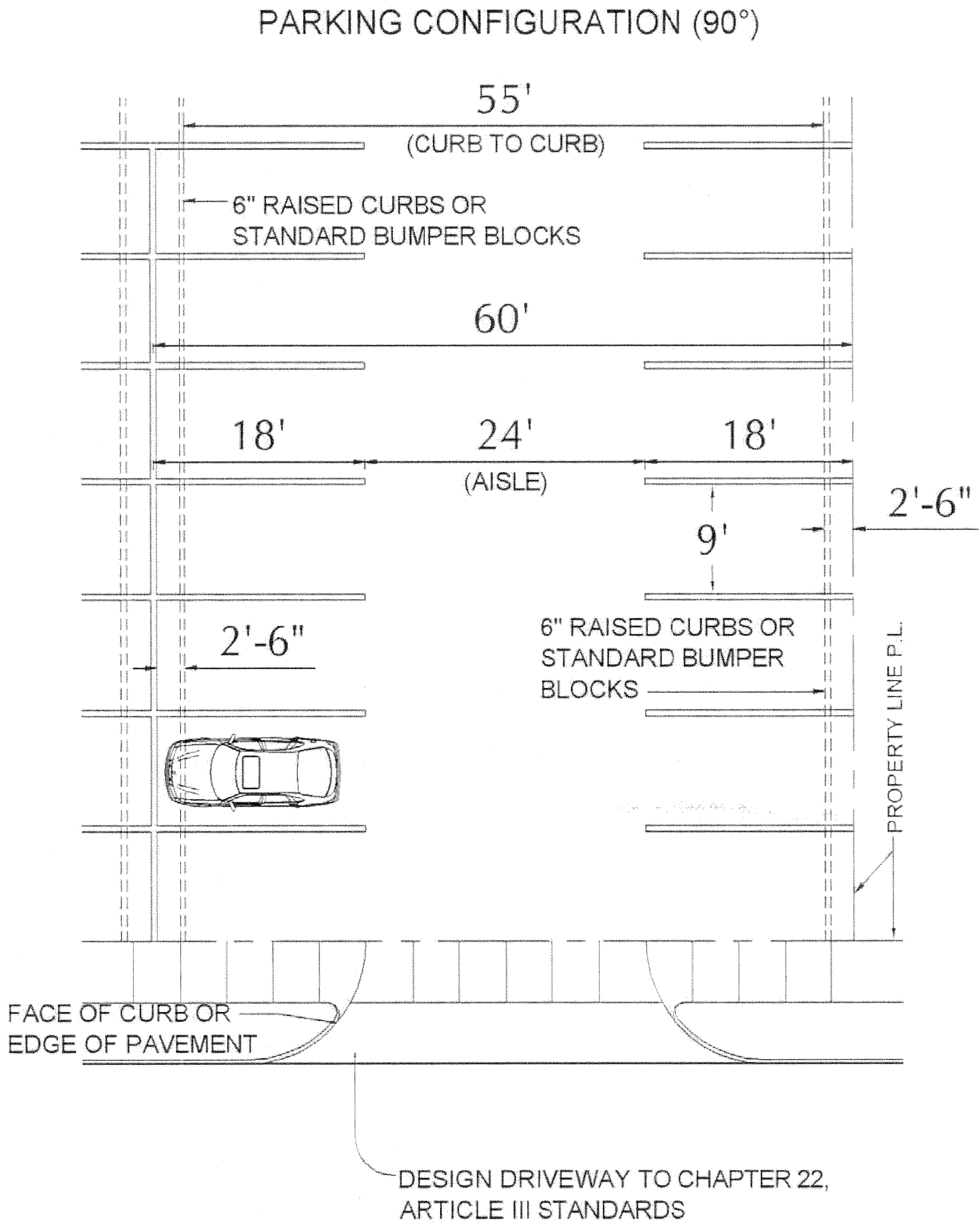
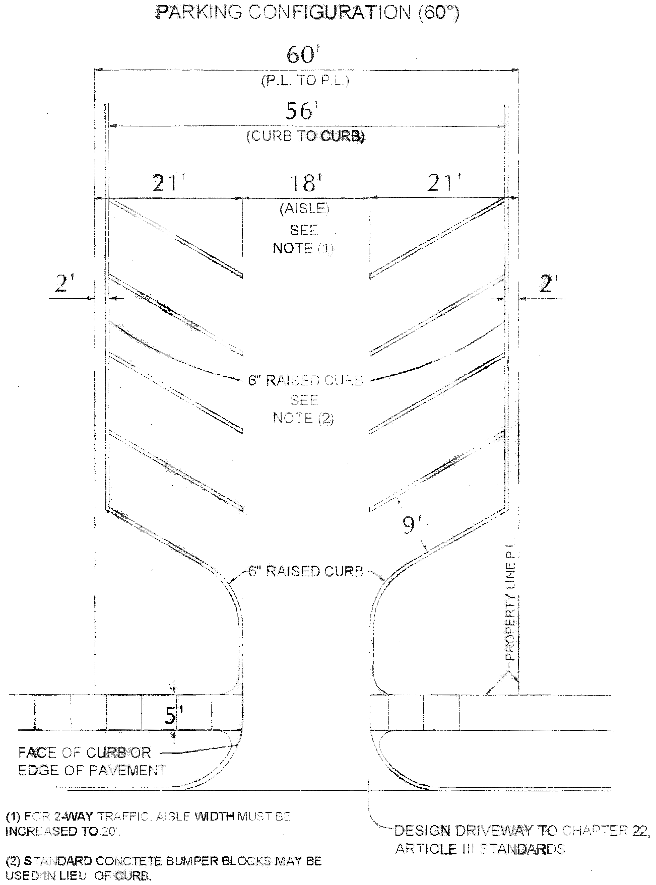
Drive aisle widths.
1.
Drive aisle widths associated with off-street parking facilities must be at least 24 feet wide if designed for two-way traffic and at least 12 feet wide if designed for one-way traffic.
2.
Drive aisles associated with off-street parking facilities, and maneuvering aisles that are located next to structures shall be separated from the structures by a walkway or open area at least four feet wide. The walkway or open area shall be protected by a six-inch-high concrete curb or a bumper guard at least two feet high.
3.
Parking spaces may be located immediately adjacent to buildings or structures without a four-foot walkway if the spaces are provided with a bumper guard. This can only be done when there is no public access to the building on the wall next to the parking area.
4.
A drive-through window shall not overhang or extend more than one foot into any parking or drive aisle.
(Ord. No. 105-22, § 1, 11-1-2022)
27-601-15
Parking layout and design standards.
A.
The purpose of this subsection is to act as a guide in the design and layout of off-street parking facilities.
B.
The tendency when designing parking lots is to crowd as many parking spaces as possible into the allotted space by reducing standards, such as narrowing parking stalls and aisles. The best design, however, should give full consideration to all design factors that improve the operation of the facility. These include internal movement, maneuvering of cars, convenience of patrons and security of vehicles.
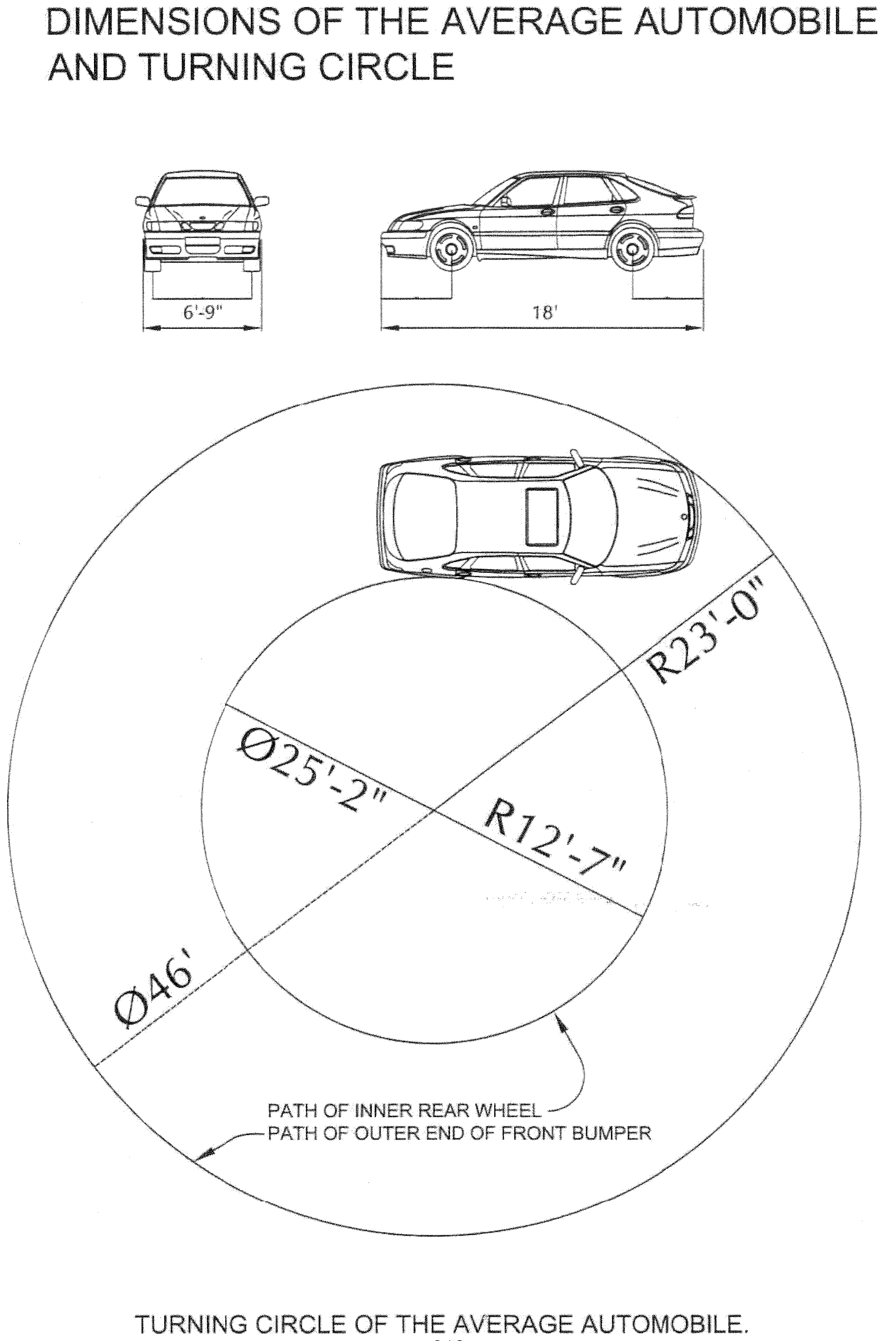
C.
The average automobile is 18 feet, zero inches long and six feet, nine inches wide. Adding to these limits allowances for opening doors, the relative skill of drivers, the turning radius of the average automobile and a margin for safety, the following standards have been established. Parking areas built to these specifications will allow 80 percent of all cars to park with relative ease in one maneuver.
D.
In the larger lots, the greatest economy of space can be accomplished by placing the stalls at right angles to the aisles. Acute angle parking allows fewer stalls for a given length of curb or aisle than right angle parking, but is more easily accessible to drivers. In addition, acute angle parking allows aisles that are narrower and permits the use of lots which are too narrow for right angle parking. Acute angle parking requires that the first stall be placed a minimum distance from the property line on sidewalk. This is a safety measure to protect and separate occupants of the sidewalk from vehicles backing out of the stall.
E.
Barrier curbs are required when parking lots continue into an adjoining property line or sidewalk. Their placement depends upon the angle for which the parking is planned.
F.
The movement of cars within parking lot facilities requires consideration of entrance and exit locations, aisle widths and the angle of parking. One-way, counterclockwise movement is desirable, where feasible, to improve internal traffic circulation and help to reduce congestion.
G.
The number of entrances and exits should be held to a minimum to reduce conflicts with street and sidewalk traffic. It is highly desirable that exits and entrances be separated from each other with curbing or landscape islands.
(Code 1992, § 27-601; Ord. No. 3-14, § 1(att.), 1-7-2014)
Sec. 27-602. - Design guidelines.
27-602-1
Applicability.
A.
The design guidelines apply to all new multifamily, nonresidential development in residential zones, transitional, commercial, and industrial development within the city. In areas where the downtown or Belle Grove design standards apply, those standards will control over these in the case of conflict.
B.
The design guidelines apply to existing multifamily, nonresidential development in residential zones, transitional, commercial, and industrial development within the city when rehabilitation (renovation, restoration, modification, addition, or retrofit) is proposed to the exterior of a structure or site will: (1) increase the gross square footage of the structure by 50 percent or greater and (2) shall also include any cumulative building additions from the effective date of this ordinance that over a five-year period amount to a 50 percent or greater increase in square footage.
C.
Rehabilitation projects shall conform to the guidelines to the greatest extent possible.
D.
All developments in compliance with these regulations shall not be renovated, remodeled, altered, or repaired so that the development will be in noncompliance with these regulations.
(Ord. No. 47-10, § 2, 10-5-2010; Ord. No. 17-11, § 2, 3-1-2011)
27-602-2
Site character.
A.
Intent. To encourage on-site and off-site compatibility of development while considering the relationship between site design and the existing surrounding environment. Site character includes consideration of: physical and natural features of land; building placement; vehicular access; circulation and parking; pedestrian access; preservation and buffering of views; surrounding development; and community character and aesthetics.
1.
The design and style of the development should work with the site.
2.
Parking and internal traffic circulation should account for the interaction between pedestrians and vehicles.
3.
Building and street layout should define a uniform and cohesive development.
B.
Definitions. Design-related definitions can be found in article 27-200 of this chapter.
C.
Grading and drainage.
1.
Where possible, new development should maintain the natural topography of the existing site. Extensive grading or unusual improvements which change the natural slope or drainage of the site are strongly discouraged.
2.
Site drainage patterns shall be designed to prevent surface drainage from collecting on and/or flowing across pedestrian areas.
3.
The use of retaining walls is encouraged to reduce the steepness of manmade slopes and to provide pockets or stepped terraces for revegetation and landscaping.
4.
Detention areas should be self-contained within a lot or parcel that contains a building site.
5.
Development must meet the city's drainage standards.
D.
Circulation.
1.
Development projects must be designed to minimize traffic and/or congestion on neighborhood streets. With the exception of Rogers Avenue and other extremely high volume routes as identified by the engineering department, traffic should be routed from the development onto the adjacent streets with the greatest traffic capacities.
2.
The design and configuration of driveways should be determined based on the size of development and capacity of streets. For example, a large, traffic-generating development with a citywide or regional drawing radius should provide sufficient driveway space for ingress and egress with turn lanes as determined by the city onto arterial level or higher streets.
3.
The number of external entrances should be consistent with existing or anticipated design of adjacent streets.
4.
Access points and driveways should be planned and shared between commercial properties, with access easements noted on plats. All development must comply with the city access management standards in section 27-603.
5.
Curb cuts should be minimized and concentrated at mid-block.
6.
A noticeable gateway or landmark appropriate to the scale and size of the development shall be created at primary entryways into the development. Building placement, landscaping, gates, entry monuments, specialty lighting, and other design elements can be used to create this design effect.
7.
There shall be a hierarchy of internal circulation.
a.
Parking areas must have parking lanes and driving lanes.
b.
There shall be limited access to driveways, which shall be provided from driving lanes wherever possible.
c.
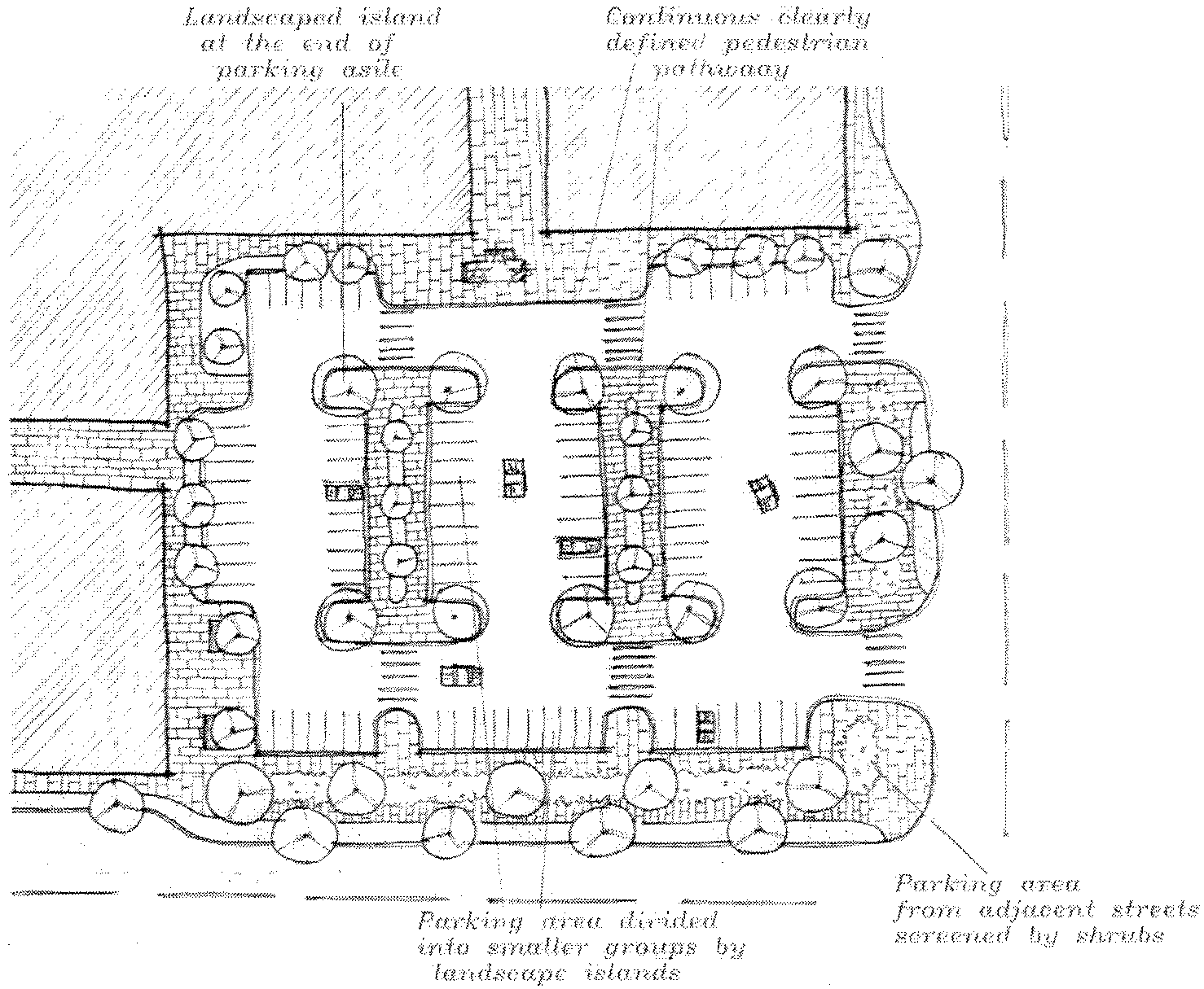
Circulation patterns within parking areas shall be defined by curbs and landscaped islands.
d.
Where possible, groups of buildings should have dedicated service access lanes.
8.
Internal vehicular and pedestrian circulation must connect in a manner obvious to users.
9.
To the maximum extent possible, there shall be pedestrian circulation from the perimeter of the site to the principal customer entrance to all buildings. Within the site, there shall be pedestrian connections provided to all pedestrian activities, including transit stops, street crossings, open space, building and store entry points, and adjacent pedestrian systems.
10.
Sidewalks in front of buildings must be designed to accommodate pedestrian activity both for that use and for movement between uses.
11.
Internal pedestrian walkways within parking lot or drive areas must be distinguished from other surfaces.
12.
Pedestrian and bicycle connections must be clearly defined. Where these connections are made in a combination of two or more of the following ways, side and rear setbacks may be incorporated into parking or landscape requirements:
a.
Six-inch vertical curb.
b.
Trellis.
c.
Special railing.
d.
Bollards.
e.
Special paving surface.
f.
Low seat wall or other architectural features.
g.
Pedestrian-scale lighting.
h.
Pavement striping or painting.
13.
Site design should integrate and facilitate access to public transit and safety vehicles.
E.
Parking.
1.
Surface parking and drive-through facilities should be located to the maximum extent possible behind buildings or in the interior of a block. Front façades and entranceways should not be oriented toward parking areas. Where parking is located behind buildings or within the interior of a block, side and rear setbacks may be used for parking spaces and landscaping.
2.
Parking areas must be visually screened from adjacent streets by walls, shrubs, trees, or other design elements pursuant to subsection 27-602-3. The required landscaping may constitute part of the screening.
3.
Parking lot curb cuts must be designed and minimized to reduce conflicts between pedestrians and automobiles.
4.
Parking lots should be divided into blocks of 40 to 50 spaces. Where blocks are not easily defined, groups of 20 spaces should be divided by a landscaped median island at least the size of one stall.
5.
Accessible parking must be provided according to the city requirements.
6.
Parking lots should include appropriately marked locations with racks for bicycle parking.
7.
Dead-end parking (parking without a clear turnaround area) should be avoided and shall not be permitted on any non-infill or redevelopment projects.
8.
Structured parking (e.g., parking decks or ramps) shall conform to the following:
a.
Structured parking adjacent to a street shall provide an active front with pedestrian-oriented uses.
b.
Structured parking shall integrate with adjacent buildings by using similar materials, alignments, and architectural finishes.
F.
Phased development. If a development is to be built in phases, each phase shall include an appropriate share of the proposed streets and circulation system, landscaping and outdoor spaces, screening, and other site and architectural amenities of the entire project. The extent of these improvements shall be determined for each phase of a specific project during the time of project development approval, but may not be based solely upon a proportional or equal share of the entire site. Requirements for a phased project may include off-site improvements.
(Ord. No. 47-10, § 2, 10-5-2010; Ord. No. 17-11, § 2, 3-1-2011; Ord. No. 105-22, § 1, 11-1-2022)
27-602-3
Landscaping and screening.
A.
Applicability.
1.
The landscaping and screening requirements of the design guidelines apply to all new multifamily, nonresidential development in residential zones, transitional, commercial, and industrial development within the city. In areas where the downtown or Belle Grove design standards apply, those standards will control over these in the case of conflict.
2.
The design guidelines apply to existing multifamily, transitional, commercial, and industrial development within the city when rehabilitation (renovation, restoration, modification, addition, or retrofit) is proposed to the exterior of a structure or site will: (1) increase the gross square footage of the structure by 50 percent or greater, and (2) shall also include any cumulative building additions from the effective date of this ordinance that over a five-year period amount to a 50 percent or greater increase in square footage.
3.
Rehabilitation projects shall conform to the guidelines to the greatest extent possible.
4.
Industrial, storage and distribution buildings when constructed along major arterial or boulevard streets as classified by the master street plan, or adjacent to residential zoning districts or single-family development, and/or those buildings at the perimeter of an industrial subdivision shall provide perimeter landscaping only.
5.
Parking lots used solely for the display of vehicles at an approved auto and vehicle dealer are required to provide perimeter landscaping only.
6.
Development or properties in compliance with these regulations shall not be renovated, remodeled, altered, or repaired so that the site will be in noncompliance with these regulations.
7.
Landscaping and screening requirements shall not apply to a new structure on an existing development when: (1) the new structure does not increase the gross square footage of the existing structures by 15 percent and (2) shall not include any new structures that cumulatively amount to a 15 percent or greater increase in square footage of the existing development over a five year period.
B.
Perimeter landscaping. Perimeter landscaping requirements along public rights-of-way are as follows:
1.
A ten-foot-wide landscaped area is required and shall be located on the property parallel and adjacent to the public street right-of-way line.
2.
The minimum requirement for a planting strip will be one tree and ten shrubs for every 50 linear feet of right-of-way frontage.
3.
If public utilities are adjacent to the right-of-way line and prohibit trees from being installed within the ten-foot wide area, the following planting methods may be utilized:
a.
Ten-foot landscape buffer may commence adjacent to the utility easement; or
b.
The required minimum number of trees may be installed interior to the site provided they are visible from the right-of-way.
c.
All required shrubbery shall be located within the ten-foot-wide area adjacent to the right-of-way or utility easement as noted in (a) above.
4.
To ensure that landscape materials do not constitute a sight hazard, a clear sight visibility triangle shall be observed at all street intersections or intersections of driveways with streets. Within the designated sight visibility triangle, no landscape material exceeding 24 inches in height shall be permitted; provided, trees may be permitted as long as only the tree trunk is visible between the ground and eight feet above the ground and the tree does not otherwise present a traffic visibility hazard. The dimensions of the sight visibility triangle are as indicated in the diagram for driveways for street intersections in section 27-503-3.
C.
Parking lot screening. Parking lot screening shall be placed in the ten-foot landscaped area reserved for the perimeter landscaping. The parking lot screening can satisfy the perimeter landscaping requirements, when the parking lot screening is installed in compliance with one of the three options below and where trees are planted at the required spacing of one tree for every 50 linear feet. When required by section 27-602-2E, parking lots, maneuvering aisles, and internal access roads (except driveways) shall be visually screened by one or a combination of two or more of the following:
1.
Approved landscaping materials shall be spaced to form a solid continuous visual screen. Where shrubs are used they shall be evergreen in nature, be at least 24 inches tall at the time of planting, and be spaced closely enough together so as to create a seamless row of screening/buffering and reach the required height within 24 months after the initial installation.
2.
A solid masonry or vinyl fence or wall that is compatible with the principal structure or development. Where a masonry or vinyl fence or wall is utilized for the parking lot screening, the perimeter landscaping required by subsection 27-602-3B must be installed on the right-of-way side of the fence but not in the right-of-way. Where fences or walls are used they shall be no more than four feet in height, as measured from the surface of the parking lot, except for those that are constructed as part of a comprehensive security fence.
3.
Earth berms shall be gently rolling in nature so as to appear natural and have a maximum slope ratio of 3:1 (horizontal run to vertical rise) and a recommended slope of 4:1. Where a berm does not reach the minimum required screening height, additional screening measures shall be installed to complement the berm. Berms and approved landscaping materials shall be adequately spaced to form a solid continuous visual screen and reach the required height within 24 months after the initial installation.
All parking lot screening shall be a minimum of three feet above the finish elevation of the parking lot. All planted materials shall reach the required height within 24 months after the initial installation. Screening shall be installed in a manner so that it does not impair the sight lines of driveways or intersections.
D.
Height of screening. The height of a screening buffer, except for parking lot screening required by subsection 27-602-3C, shall comply with the following:
1.
Visual screening walls, fences, or berms and fences in combination shall be four to six feet high measured from the natural grade, in order to accomplish the desired screening effect.
2.
Vegetation shall be four to six feet high measured from the natural grade, in order to accomplish the desired screening effect. The required height shall be achieved with vegetation capable of growing up to four to six feet in height within 12 months after the initial installation.
E.
Interior landscaping for vehicular use areas.
1.
Requirement. For any open vehicular use area, excluding loading and unloading zones, containing more than 6,000 square feet of area, or 20 or more vehicular parking spaces, the owner shall provide interior landscaping in addition to the previously required landscaping along the public right-of-way. Interior landscaping may be peninsular or island types. Applicant shall submit square footage of the paved surface area.
2.
Tree island. One island containing a tree shall be installed for every 20 parking spaces. The width of a tree island shall be a minimum of eight feet; the area shall be a minimum of 150 square feet.
3.
Setbacks. In all required interior landscape areas, trees are required to be set back a distance of four feet from the edge of pavement.
4.
Vehicle overhang. Parked vehicles may overhang the interior landscaped area no more than two and one-half feet, provided there are concrete or other wheel stops are installed to insure no greater overhand of the landscaped area.
F.
Landscape materials.
1.
Materials. Required landscape areas shall be planted using tree, shrub, grass or groundcover plants identified in subsections (e), (f), (g) and (h). Any owner desiring to plant unlisted plants may make a written application to the administrative officials of the city. Any decision of the administrative officials is subject to appeal to the board of zoning adjustment according to the provisions of section 27-337 of these regulations.
2.
Plants. Artificial plants are prohibited. All plant materials shall be living plants.
3.
Quality. Plant materials must conform to the standards of the American Association of Nurserymen and shall have passed any inspections required by state regulations.
4.
Deciduous trees. All planted deciduous trees shall have a minimum thickness of two inches at the aboveground trunk at time of planting.
5.
Evergreen trees. Evergreen trees shall be a minimum of five feet tall at the time of planting.
6.
Grass or groundcover. Grass may be sodded or seeded. In drainage swales or other areas subject to erosion, solid sod, erosion-reducing net, or suitable mulch must be used and nurse grass seed shall be sown for immediate protection until complete coverage is achieved.
a.
Grass sod shall be clean and free of weeds and noxious pests or diseases.
b.
In areas where groundcover rather than grass is used, the groundcover shall be planted to present a finished appearance and will grow to 75 percent of complete coverage after one complete growing season.
G.
Maintenance. The developer and/or owner shall be responsible for the perpetual maintenance and preservation of the landscaping.
1.
All landscaped areas must be kept:
a.
In a proper, neat and orderly appearance;
b.
Free from refuse and debris;
c.
With dead plant material replaced within one year of the death of the plant material or by the next planting period, whichever comes first;
d.
With other defective landscape materials replaced or repaired within three months of defect; and
e.
Irrigated with an automatic irrigation system or the applicant shall supply the city with a maintenance plan specifying the method of keeping the plants alive with proper watering.
H.
Allowed tree species.
1.
Primary list. The following trees have been found to be best suited to this area and yet require the least amount of maintenance. This list, along with the secondary list, represent trees which may be planted in the required landscaping area. Additional selective trees may be substituted when proven to be hearty to this region:
2.
Secondary list. The following trees have been found to be the next best suited to this area but require increased maintenance:
I.
Shrub species.
1.
Primary list. The following shrubs have been found to be best suited to this area and yet require the least amount of maintenance. This list, along with the secondary list, are those shrubs which may be planted in the required landscaping area. Additional selective shrubs may be substituted when proven to be hearty to this region. Minimum plant size for either list is three gallons:
2.
Secondary list. The following shrubs have been found to be the next best suited to this area but require increased maintenance:
J.
Grasses. The following grasses may be used:
Bermuda grass
Bermuda grass hybrids
Big Bluestem
Centipede
Emerald zoysia
Inland Sea-Oats
Little Bluestem
Mayer Z-52 Zoysia
Pink Muhly Grass
Prairie Dropseed
Side Oats Grama
Split Beard Bluestem
St. Augustine
Switchgrass
K.
Groundcovers.
1.
Primary list. The following groundcovers have been found to be best suited to this area and require the least amount of maintenance. This list, along with the secondary list, are those groundcovers which may be planted in the required landscaping area. Additional selective groundcovers may be substituted when proven to be hearty to this region.
2.
Secondary list. The following groundcovers have been found to be the next best suited to this area but require increased maintenance:
L.
Xeriscape option.
1.
As a low maintenance option, the city encourages the use of landscaping which promotes water conservation and is drought resistant. The term "xeriscape" means a planting practice that relies on minimal irrigation. Conserving resources such as fertilizer, fuels, water, labor, time and money are important elements of this. By encouraging the reestablishment of native plant communities, xeriscape uses plants adapted to specific climate conditions and locations as alternatives to or reductions of traditional turf grass areas.
2.
Xeriscape has seven basic principles to follow in the use of trees, shrubs, perennials and turf grasses which can be adapted to prolonged periods of drought and/or reduced watering regimens. The following steps are key to a successful xeriscape program:
a.
Planning and design. Develop a plan by situating and locating all the existing elements of a yard/greenspace area. Consider the conditions of view, slope, wind and light to develop a new landscape plan. Group plants with similar water and shading needs together.
b.
Soil analysis. Determine the soil type and identify any problem spots which may need soil improvements. Add organic matter such as peat moss or manure to enrich soils.
c.
Appropriate plant selection. Plants should be appropriately selected for the area (region) they are to be used in and for their ability to withstand drought conditions and promote water conservation.
d.
Practical turf grass areas. Reduce the amount of landscape/greenspace area devoted to a grass lawn to 50 percent or less. This will reduce the amount of maintenance required to irrigate and mow the area.
e.
Efficient irrigation. Irrigation should be grouped according to the type and condition of the plants rather than a fixed schedule. Drip watering can be used for many plants and conserves water. Limit sprinklers to grass areas only.
f.
Use mulches. Organic mulches minimize weed growth, reduce evaporation, slow erosion and help prevent temperature fluctuations.
g.
Appropriate maintenance. Proper pruning, weeding, fertilization and proper attention to the irrigation system will ensure the quality of the xeriscape.
3.
For those residents or businesses who want to pursue xeriscape landscaping, the following guidelines are suggested:
a.
Install rain sensor smart devices on irrigation systems with automatic irrigation controls to conserve water when rainfall has or is occurring.
b.
Use at least 50 percent native vegetation which is indigenous to Arkansas in the xeriscape design.
c.
Adhere to the following guidelines for the percentage of xeriscaped area to turf grass lawn areas:
1.
Single-family and duplex residential: a maximum of 80 percent turf grass lawn and minimum of 20 percent xeriscape for the pervious area.
2.
Multifamily residential: a maximum of 60 percent turf grass lawn and minimum of 40 percent xeriscape for the pervious area.
3.
Commercial, office, industrial and other developments: a maximum of 50 percent turf grass lawn and minimum of 50 percent xeriscape for the pervious area.
4.
Homebuilders or developers subdividing lots or constructing new single-family residential homes are encouraged to offer a xeriscape option in any series of landscaping options offered to prospective home buyers.
5.
Use water conservation efficient irrigation systems. Trees, shrubs, flowers and groundcover should be irrigated with low volume drip emitters, micro-sprayers or soaker hoses. The sprinkler irrigation systems should be reserved to the turf grass lawn areas.
6.
Use organic mulches such as wood chips, bark or pine straw to minimize evaporation, reduce weed growth, slow erosion and help prevent soil temperature fluctuations.
7.
Group similar landscaping together according to their watering requirements to minimize overall water usage and reduce the amount of maintenance required.
8.
The following trees and plants are recommended:
(Ord. No. 47-10, § 2, 10-5-2010; Ord. No. 17-11, § 2, 3-1-2011; Ord. No. 29-14, § 1(att.), 6-3-2014; Ord. No. 50-14, § 1(att.), 9-2-2014; Ord. No. 36-20, § 1(att.), 5-5-2020; Ord. No. 86-20, § 2(att.), 10-6-2020; Ord. No. 99-20, § 2(att.), 11-10-2020; Ord. No. 105-22, § 1, 11-1-2022; Ord. No. 11-23, § 1, 2-7-2023; Ord. No. 36-24, § 1, 4-2-2024; Ord. No. 92-23, § 1, 11-7-2023)
27-602-4
Architectural design of structures.
A.
Purposes. Design requirements for new construction and additions to existing commercial and office buildings shall be required in order to:
1.
Protect and enhance the city.
2.
Provide good civic design and arrangement.
3.
Preserve property values of surrounding property.
B.
Applicability.
1.
The design guidelines apply to all new multifamily, nonresidential development in residential zones, transitional, commercial, and industrial developments within the city. In areas where the downtown or Belle Grove design standards apply, those standards will control over these in the case of conflict.
2.
The design guidelines apply to existing multifamily, commercial and industrial development within the city when rehabilitation (renovation, restoration, modification, addition, or retrofit) is proposed to the exterior of a structure or site will: (1) increase the gross square footage of the structure by 50 percent or greater, and (2) shall also include any cumulative building additions from the effective date of this ordinance that over a five-year period amount to a 50 percent or greater increase in square footage.
3.
Rehabilitation projects shall conform to the guidelines to the greatest extent possible.
4.
Buildings in compliance with these regulations shall not be renovated, remodeled, altered or repaired so that the building will be in noncompliance with these regulations.
C.
Transitional and commercial building design standards.
1.
Any development that contains more than one building shall incorporate a recurring, unifying and identifiable theme for the entire development.
2.
The predominant (51 percent of the gross wall area or greater) exterior building façade of all commercial buildings must be of high quality materials such as brick, wood, native stone, tinted glass, stucco, exterior insulated finished systems (EIFS), cementious siding (e.g., Hardie Board), tinted/textured concrete masonry units, or other siding materials as approved by the director. Smooth-faced concrete block, plain or untextured tilt-up panels and prefabricated steel panels are prohibited as the predominant façade. Applicants with commercial development adjacent to residential development may incorporate residential materials on the side of the development that faces the residential development.
3.
All façades of a building that are visible from the finished grades of adjoining properties or public streets shall have design characteristics similar to the building's front façade. This shall be implemented by requiring the same treatment as discussed in subsection C.2 of this section above.
4.
All mechanical equipment, heating/cooling systems, trash receptacles and utility boxes shall be completely screened from adjoining properties and street right-of-way.
a.
For ground-mounted equipment, the screening shall consist of a wall, fence, or approved landscaping or the equipment must be enclosed within a building.
b.
For roof-mounted equipment, the screening shall be architecturally incorporated into the roof design and shall consist of materials that are visually compatible with the supporting building.
c.
Exhaust fans, utility boxes, and ductwork located on building facades not visible from a street right-of-way or property zoned or developed residential may match the permanent color of the surface from which they project.
5.
Barbed wire, sheet metal, wood slat, split log, tarps or other nonconventional fencing material are prohibited.
6.
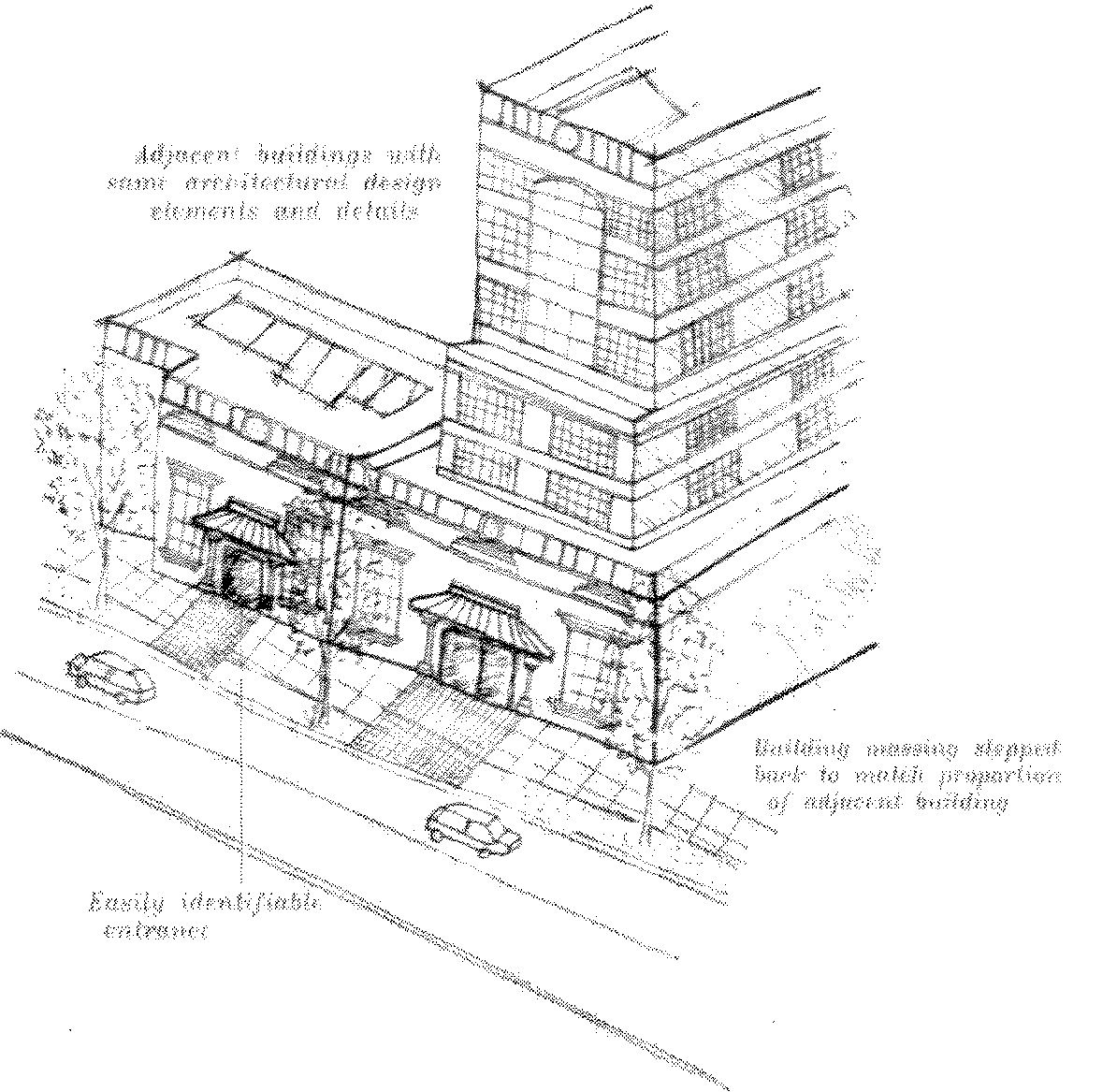
Transitional and commercial building elements.
a.
The main entrance of a building should face a pedestrian plaza or space with a direct pedestrian connection to the street.
b.
Buildings should be located in such a manner as to minimize conflicts between pedestrians and automobiles.
c.
Buildings should be oriented primarily to the street, with street-oriented retail or service spaces.
d.
Retail shops at street level should have direct access to and from the sidewalk.
e.
Entrances should be easily identifiable as primary points of access to buildings.
f.
Corner buildings at gateways or prominent intersections should be designed to emphasize the gateway or intersection location. This may include major architectural expression in the façade, roof form and/or massing, such as:
1.
Larger bulk.
2.
Tower forms.
3.
Peaked roofs.
4.
Over-sized windows.
5.
Sloped parapets and appurtenances.
g.
Building projections. All building projections, including, but not limited to, chimneys, flues, vents, gutters and down spouts, shall match the permanent color of the surface from which they project or match the building's trim color.
7.
Auto impoundment or holding yards shall be screened with a minimum six- to eight-foot opaque fence constructed of wood or masonry.
8.
A permanent six-foot opaque screening fence, wall or landscape buffer shall be provided along any side or rear property line adjacent to property zoned or developed for residential purposes including alleys.
9.
Linear or strip development is discouraged, including linear open air centers.
10.
Pad sites shall be clustered together to define street edges and entry points or to enclose and create interesting places between buildings, such as public outdoor seating, landscaped areas, or other focal points.
11.
Buildings, walls, trees, topography, and other site features shall be oriented and arranged to define circulation areas and lend a human scale to the development.
12.
Shared parking agreements between adjacent or closely related developments are strongly encouraged.
D.
Multifamily building standards. The following standards shall apply to multifamily (three or more units) development, including row house developments:
1.
New building design should respect the context of adjacent residential neighborhoods, including the height, scale, mass, form and character of surrounding developments.
2.
The predominant (51 percent of the gross wall area or greater) exterior building façade of all multifamily buildings must be of high quality materials such as brick, wood, native stone, tinted glass, stucco, exterior insulated finished systems (EIFS), cementious siding (e.g., Hardie Board), tinted/textured concrete masonry units, or other siding materials as approved by the director. Smooth-faced concrete block, plain or untextured tilt-up panels and prefabricated steel panels are prohibited as the predominant façade.
3.
Building orientation. Multifamily residential structures adjacent to a public street should be sited parallel with the street to provide a traditional residential orientation, and should maintain consistent setbacks between the street and residential structures.
a.
Along interior property lines, multifamily structures should be oriented in a more perpendicular direction to adjacent lower-density residential uses or zoning districts, or adjacent commercial or industrial uses or zoning districts. When parallel orientation is necessary, building setback from the adjacent use or district boundary shall be increased by at least 50 percent.
b.
Primary structures shall be located and designed that residents can easily observe and gain entry to the common open spaces, circulation paths and access points into the development.
c.
Buildings must not have a solid, blank façade facing the street.
4.
Mass and form.
a.
Building design should incorporate visually heavier and more massive elements at the building base, and lighter elements above the base.
b.
All buildings shall be designed to provide complex massing configurations with a variety of different wall planes and roof planes.
c.
The façades of single-family attached row homes shall be articulated to differentiate individual units.
5.
Architectural detail.
a.
Individual buildings should have a definitive, consistent style. Various architectural styles should not be mixed in the same building.
b.
All sides of a multifamily building shall display a similar level of quality and architectural interest.
c.
All building entries adjacent to a collector, local residential street, or private drive with on-street parking shall be designed at a pedestrian scale.
d.
Fronts of buildings should be articulated through the use of bays, insets, balconies, porches, or stoops related to entrances and windows.
e.
All multifamily building elevations shall contain windows, except when necessary to ensure privacy for adjacent property owners.
f.
Windows should be located to maximize the possibility of occupant surveillance of entryways, recreation areas, and laundry areas.
g.
Wall planes. No façade shall exceed 65 horizontal feet. Each façade greater than 65 feet in length, measured horizontally, shall incorporate wall plane projections or recesses having a depth of a least three percent of the length of the façade and extending at least 20 percent of the length of the façade.
h.
Balconies, porches and stairways. Multifamily residential structures shall provide at least 75 percent of the total dwelling units with a minimum of one private outdoor yard, patio or balcony that consists of a minimum of six feet along one dimension with a total minimum of 36 square feet. The use of exterior staircases is strongly discouraged.
i.
Roof design. Multifamily residential structures shall be designed to avoid any continuous roofline longer than 65 feet. Rooflines longer than 65 feet shall include at least one vertical elevation change of at least three feet.
j.
Building projections. All building projections, including, but not limited to, chimneys, flues, vents, gutters and down spouts, shall match the permanent color of the surface from which they project or match the building's trim color.
k.
Entrances.
1.
Pedestrian entry to the site from the fronting street shall be emphasized through landscaping, lighting special paving, gateways, arbors, and/or other similar features.
2.
Long, linear, and/or hidden stairways or corridors shall be avoided.
3.
Covered entrances (i.e., awnings or canopies) shall be provided as protection from bad weather and as a transition from indoor to outdoor.
6.
All trash receptacles shall be completely screened with a permanent opaque screen fence. Individual trash receptacles provided by the city Sanitation Department shall not be required to be screened.
7.
Outdoor lighting shall comply with section 27-602-5.
8.
A permanent opaque six-foot screening fence, wall or landscape buffer shall be provided along any side or rear property line adjacent to property developed or zoned single-family including alleys.
E.
Industrial building standards. The following standards shall apply to industrial, storage and distribution buildings when constructed along major arterial or boulevard streets as classified by the master street plan, or adjacent to residential districts, and/or those buildings at the perimeter of an industrial subdivision.
1.
Each primary entrance for employees or visitors that faces a public street should be emphasized through the use of differing colors or materials, arches, arcades or other architectural treatments.
2.
All front façades of primary structures, all façades that face a public right-of-way, and all sidewall façades within 40 feet of the front façade, shall be made of masonry (brick, stone and/or stucco) or tilt-up concrete panels (textured or untextured), wood, native stone, tinted glass, exterior insulated finished systems (EIFS), cementious siding (e.g., Hardie Board), or other siding materials as approved by the director.
3.
Façades of the primary structure should incorporate architectural relief through the use of at least two of the following tools: reveals, visible joint patterns, projected sills, belt courses, repeating brick header and stretcher courses, or differing colors and textures.
4.
All primary structures with roofs with a pitch of less than two to 12 shall be screened by a parapet wall or fascia.
5.
All trash receptacles shall be screened with a permanent opaque screening fence.
6.
Outdoor lighting shall comply with subsection 27-602-5.
7.
Screening requirements.
a.
Industrial-1 (I-1).
1.
Areas used for outdoor storage or display shall be maintained so that excessive dust, fumes or odors will not be produced by continued use.
2.
Buffering, landscape, and fence screening shall be required when abutting residentially zoned or developed properties. The minimum buffering requirements shall consist of a six-foot-high screen fence, landscaping (trees, shrubs, and groundcover,) or a berm. All buffer areas shall be a minimum of ten feet in width. The planning and zoning department shall approve location, size, plant species, and number. The buffering shall be in addition to minimum open space requirements.
3.
Auto impoundment or holding yards shall be screened with a minimum six- to eight-foot opaque fence constructed of wood or masonry.
b.
Industrial-2 (I-2).
1.
Outdoor storage of equipment, materials or merchandise not actively offered for sale shall be surrounded by a sight-proof screen which restricts their view from the public.
2.
Areas used for outdoor storage or display shall be maintained so that excessive dust, fumes or odors will not be produced by continued use.
3.
Buffering, landscape, and fence screening shall be required when abutting residentially zoned or developed properties. The minimum buffering requirements shall consist of a six-foot-high screen fence, landscaping (trees, shrubs, and groundcover,) or a berm. All buffer areas shall be a minimum of ten feet in width. The planning and zoning department shall approve location, size, plant species, and number. The buffering shall be in addition to minimum open space requirements.
4.
Auto impoundment or holding yards shall be screened with a minimum six- to eight-foot opaque fence constructed of wood or masonry.
c.
Industrial-3 (I-3). All permitted uses shall conform to the following specific regulations as well as the bulk and area regulations of this zone.
1.
All such uses shall be completely enclosed by an eight-foot high opaque screen. Alternate fencing materials may be substituted for an opaque fence on the rear and side of the site when the use abuts an I-3 zone and the portion may not be seen from a public street or road. The determination shall be made by the building official.
2.
Fences adjacent to street rights-of-way shall be erected under the following guidelines:
a.
Entrances to fenced areas which are adjacent to arterial or collector streets, where an entrance is provided from such street, must be set back 60 feet from such right-of-way.
b.
Fences adjacent to local, collector or arterial streets where no entrance is provided from such street may be located on the property line adjacent to such right-of-way.
c.
No fence or screening device shall be erected so as to obstruct the vision of motorists at alley, street or driveway intersections.
d.
The storage or display of goods or merchandise outside the confines of the fenced area is expressly prohibited.
e.
No junk, parts, disabled autos or salvage material of any kind shall be stored outside or above the fence.
3.
The burning of wrecked or discarded automobiles or any parts thereof is prohibited.
4.
All signage shall meet requirements in section 27-704, however, in no case shall any provisions of this chapter be interpreted to permit the use of discarded, disabled, or wrecked automobiles, trucks, equipment, appliances, or parts to be used for advertising or identification purposes.
5.
Whenever an owner or representative of a nonconforming use under this section applies for and is granted I-3, heavy industrial zoning, he shall have a period not to exceed six months to bring the use into complete conformity with the provisions of this section.
6.
All areas unoccupied by buildings, parking lots or used as traffic ways shall be maintained in a safe and orderly condition.
7.
Areas used for outdoor storage or display shall be maintained so that excessive dust, fumes or odors will not be produced by continued use.
8.
Buffering, landscape, and fence screening shall be required when abutting residentially zoned or developed properties. The minimum buffering requirements shall consist of a six-foot-high screen fence, landscaping (trees, shrubs, and groundcover) or a berm. All buffer areas shall be a minimum of ten feet in width. The planning and zoning department shall approve location, size, plant species, and number. The buffering shall be in addition to minimum open space requirements.
9.
Auto impoundment or holding yards shall be screened with a minimum six- to eight-foot opaque fence constructed of wood or masonry.
(Ord. No. 47-10, § 2, 10-5-2010; Ord. No. 32-11, §§ 1—3, 5-3-2011; Ord. No. 70-11, § 2, 9-6-2011; Ord. No. 26-13, § 1(att.), 6-4-2013; Ord. No. 3-14, §1(att.), 1-7-2014; Ord. No. 50-14, § 1(att.), 9-2-2014; Ord. No. 25-15, § 1(att.), 4-7-2015; altered in 2019 recodification; Ord. No. 1-21, § 2(att.), 1-5-2021; Ord. No. 88-22, 10-4-2022; Ord. No. 79-23, § 1, 10-10-2023; Ord. No. 42-24, § 1, 5-7-2024)
27-602-5
Commercial and outdoor lighting.
A.
Purpose. The city finds that the regulation of outdoor lighting is necessary to prevent misdirected or excessive artificial light caused by inappropriate or misaligned light fixtures that produce glare, light trespass (nuisance light) and/or unnecessary skyglow; and also that such regulation is necessary to discourage the waste of electricity and to improve or maintain nighttime public safety, utility, and security.
B.
Requirements. All outdoor lighting fixtures installed and thereafter maintained, other than those serving one- and two-family dwellings, shall comply with the following requirements:
1.
Where used for security purposes or to illuminate walkways, roadways, and parking lots, only shielded light fixtures shall be used.
2.
Where used for commercial and industrial purposes, such as in merchandise display areas, work areas, platforms, signs, architectural, landscape, or sports/recreation facilities, all light fixtures shall be equipped with automatic timing devices and comply with the following:
a.
Light fixtures used to illuminate flags, statues, or any other object mounted on a pole, pedestal, or platform, shall use a narrow cone beam of light that will not extend past the illuminated object.
b.
Other upward-directed architectural, landscape or decorative direct light emissions shall have at least 90 percent of their total distribution pattern within the profile of the illuminated structure.
c.
Recreational and sports facility lighting shall be shielded whenever possible. Such lighting shall have directional and glare control devices, when necessary to comply with the following section.
d.
Externally illuminated signs including commercial billboard, building identification or other similar illuminated signs shall comply with the following:
1.
Top mounted light fixtures that are shielded;
2.
When top mounted fixtures are not feasible, illumination from other positioned light fixtures shall be restricted to the sign area. Visors or other directional control devices shall be used to keep spill light to an absolute minimum.
e.
All other outdoor lighting shall use shielded light fixtures.
3.
All floodlight type fixtures, once properly installed, shall be permanently affixed in the approved position.
C.
Light trespass. All light fixtures, except street lighting and those used on one- or two-family dwellings, shall be designed, installed, and maintained to prevent light trespass, as specified below:
1.
At a height of five feet above the property line of the subject property, illuminations from light fixtures shall not exceed 0.1 foot-candles in a vertical plane on residentially zoned property.
2.
Outdoor light fixtures properly installed and thereafter maintained shall be directed so that there will not be any objectionable direct glare source visible from any property. Light fixtures near adjacent property may require special shielding devices to prevent light trespass.
D.
Illuminance and luminance requirements. Illuminance and luminance requirements shall be as set forth in the current edition of the illuminating Engineering Society of North America (IESNA) Lighting Handbook.
E.
Outdoor lighting energy conservation.
1.
All outdoor lighting not necessary for security purposes shall be reduced, activated by motion sensor devices, or turned-off during non-operating hours. Illuminated signs are excluded from this requirement.
2.
All lighting shall be designed to prevent misdirected or excessive artificial light and to maximize energy efficiency.
(Code 1992, § 27-602)
Sec. 27-603. - Access management.
27-603-1
Generally.
A.
The city engineering department shall administer the access management standards and regulations.
B.
The preliminary subdivision plat or development plan must identify the location of proposed driveways in conformance with these regulations. No additional driveways may be identified as part of the final plat process. Compliance with these provisions for infill or redevelopment will be determined on a case-by-case basis.
27-603-2
Driveway separation standards.
A.
Driveway access must conform to the specifications outlined in table 27-603-1A (minimum separation between driveways and street intersections) and table 27-603-1B (minimum separation between adjacent driveways). For purposes of measuring driveway separation, the separation standards apply to driveways on lots adjacent to the subject lot as well as to those on the subject lot itself.
B.
Offset driveways must be spaced at a sufficient distance from other driveways to allow for safe and efficient traffic flow.
C.
The preliminary subdivision plat and development plans must include information regarding existing driveways for adjacent and opposite sides of street properties.
D.
Where necessary for the safe and efficient movement of traffic, driveway access points must be limited to restricted turning movements (e.g., right turns only).
E.
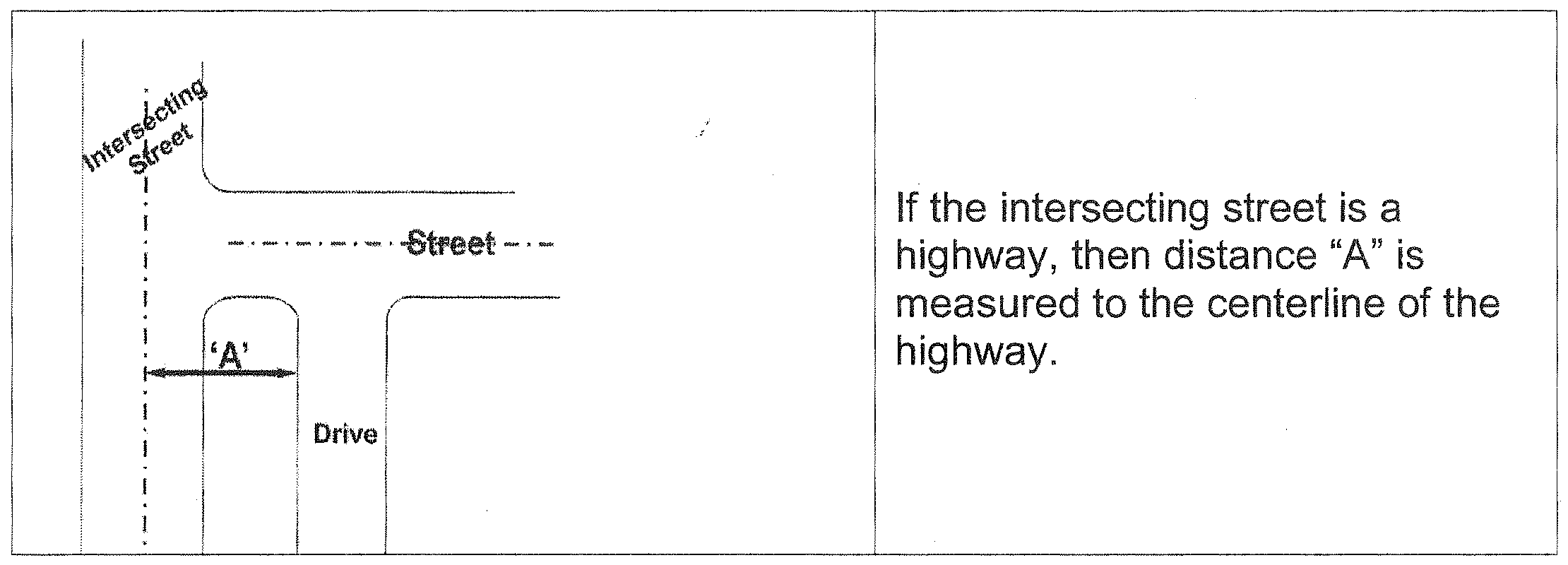
A minimum separation between driveways and street intersections must be measured as indicated in figure 27-603-1, dimension A for driveway separation and as noted in table 27-603-1A (minimum separation between driveways and street intersections) or table 27-603-1B (minimum separation between adjacent driveways).
F.
Driveways must be located as far as possible from intersections.
G.
Shared driveways are permitted and encouraged.
H.
Existing driveway access points must be redesigned where needed to safely control traffic flow, unless the redesign would deny the landowner reasonable access.
I.
Common driveways may be constructed for the joint use of adjoining properties. Documentation of the existence of common rights to driveway access (cross access agreements) is required and must be submitted either with the plat or the rezoning request.
J.
Directional driveways that restrict the movement of traffic to right-turn-only or left-turn-only are required where needed to provide traffic safety.
K.
No driveways will be permitted in areas designated as "Limits of No Access" by either the state highway and transportation department or by plat.
L.
Access separation between a driveway and an intersection shall be measured from the nearest edge of the driveway to the intersecting street centerline, except for freeways.
M.
Spacing from freeways is measured from the centerline of the nearest freeway ramp or frontage road right-of-way line (see minimum separation dimension 'A' standards) in table 27-603-1A, minimum separation between driveways and intersections).
N.
Separation between driveways is from the inside edge to inside edge of the driveway (see table 27-603-1B, minimum separation between adjacent driveways).
Table 27-603-1A. Minimum Separation Between Driveways and Street Intersection
(Dimension A in Feet)
Measured from the frontage road right-of-way.
Table 27-603-1B. Minimum Separation Between Adjacent Driveways
(In Feet)
Excludes permitted uses in residential zoning districts.
Adjacent driveway separation is measured from driveway inside edge to inside edge.
(Ord. No. 70-11, § 2, 9-6-2011)
27-603-3
Intersection design.
A.
Generally. All driveways and access facilities shall be designed to meet the grade, alignment, pavement, and channelization standards and other specifications prescribed by adopted city standards.
B.
Two-way driveways.
1.
The intersection of a two-way driveway shall intersect any arterial in a 90-degree angle.
2.
The corner radius of a 90-degree driveway shall be at least ten feet. However, residential driveways on residential or collector streets shall have a minimum radius of five feet.
3.
A minimum sight distance for vehicles egressing a driveway to an arterial shall be based on the 85th percentile speed of the roadway and the distance shown in table 27-603-3-A. The sight distance shall be measured as follows:
a.
From a point on the driveway at least 15 feet from the edge of the arterial street pavement; and
b.
From a height of eye of 3½ feet on the driveway to a height of object of 4½ feet on the arterial street.
Table 27-603-3-A.
C.
One-way driveways.
1.
One-way egress driveways shall conform to the sight distance requirements in subsection B.3 of this section, above.
2.
One-way egress driveways of less than 90 degree egress may be required by the city engineer where it is determined that is in the interest of the health, safety, and general welfare of the public.
27-603-4
Access for mixed use districts.
A.
Residential access.
1.
Access to residential lots in a mixed use district may be made from rear-access private driveways as provided below. If access is from a private driveway, the driveway shall not exceed 16 feet in width at any point between the sidewalk line and the rear of the principal building. A walkway with a minimum width of three feet shall extend from the sidewalk to the front entry.
2.
Rear-access private driveways shall be paved and maintained by a homeowners' association.
3.
Where rear-access private drives are used for residential access, the applicant may request an adjustment to the front yard setback of up to 20 percent decrease in size.
B.
Nonresidential access. Access to nonresidential lots in a mixed use district may be from a rear-access private drive or common parking areas.
(Code 1992, § 27-603)