
Polk County Unincorporated
City Zoning Code
City Zoning Code
APPENDIX A
POLK COUNTY TECHNICAL STANDARDS MANUAL
Appendix A
This Appendix is provided to establish minimum standards to be used by engineers and contractors in constructing development projects throughout the unincorporated areas of Polk County.
Section A101 - Purpose and Intent (Rev. 10/07/09 - Ord. 09-061)
This Section establishes the minimum engineering design standards applicable to all developments exclusive of private parking lots and drive aisles. The standards are intended to promote the public health, safety and welfare by insuring the improvements are designed to adequately provide for transportation and drainage features of the development.
Section A102 - Drainage Design Requirements (Rev. 10/07/09 - Ord. 09-061)
A.
Storm Sewer Design
1.
Manning's equation will be used for storm sewer design with coefficient of roughness (n) of 0.012 for concrete pipes and 0.012 for smooth lined corrugated metal pipes. Coefficient of roughness (n) for all other pipes shall be as shown in Table A1.
Table A1 Values of Coefficient of Roughness (n) for Standard Corrugated Steel (Manning's Formula)
2.
When pipe is sized using full flow conditions, the hydraulic gradient shall be at least one foot below the gutter profile. Sufficient head should be allowed at inlet entrances to force the flow to the velocity required at full flow conditions. When the design is based on partial depth flows, the depth of flow shall not be over 2/3 pipe diameter at velocities exceeding 15 f.p.s. Pipes will have a physical slope sufficient for a minimum flow velocity of two and one-half feet per second.
3.
Inlets not in sump position shall be spaced to receive 80 percent of the runoff (See Table A2) in curb and gutter or urban sections. Inlets shall be carefully placed near intersection returns to avoid flooding adjacent properties and intersections.
4.
Capacity of inlets in sump position shall not exceed 12 cubic feet per second (cfs). FDOT Standard Index Inlet Types "P" and "J," with inlet throats Type 1, 2, 5 and 6 shall be used on curbed sections. Grates shall be parallel to centerline profile grade.
5.
FDOT Standard Index ditch bottom inlets "C," "D," "E" and "H" shall be used in ditches or low areas where water would be collected. Where debris is a problem and there is no safety hazard, slots will be used.
6.
The Rational Method of analysis shall be used in the design of storm sewer systems and small culverts.
Q = CIA
Q = runoff in cubic feet per second (CFS) I = rainfall intensity in inches per hour
A = drainage areas, in acres
C = coefficient of runoff (See Tables A3 and A4)
"I" will be determined by using the intensity-duration-frequency zones and curves shown in Figure A1 and Figure A2.
7.
Time of Concentration will be determined by using Figures A3 and A4. The minimum Time of Concentration used in computations will be ten minutes.
Table A2 Maximum Capacity (Q cfs) for 80% Efficiency Total
* = Road Flooded @ cfs/% efficiency - = No data
Table A3 Runoff Coefficients ("C" Factor)
Table A4 Design Storm Frequency Factors
Figure A1 Zones for Precipitation Intensity Duration Frequency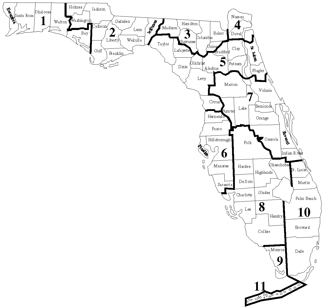
Zones for Precipitation Intensity Duration Frequency (IDF) Curves
Source: Volume 2 ___ Procedures, Florida Department of Transportation Drainage Manual
Figure A2 Rainfall Intensity Duration Curves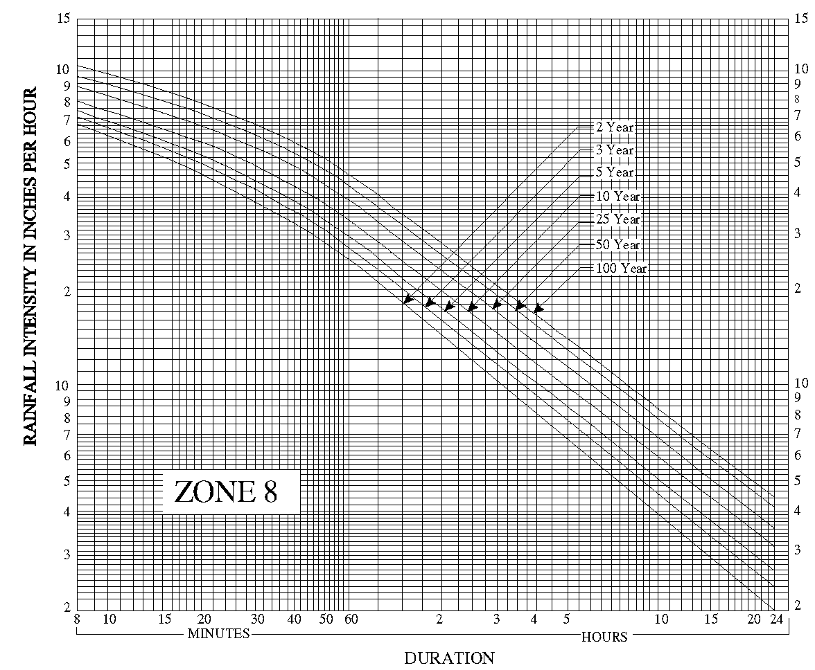
Figure A3 Overland Flow Velocities for Various Land Use Types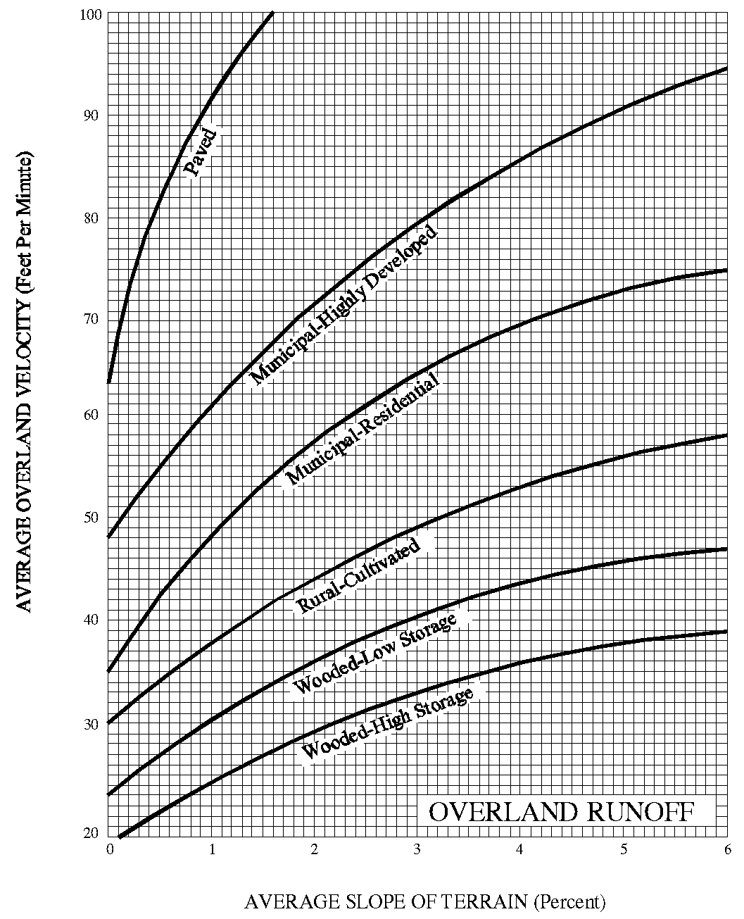
Overland Flow Velocities for Various Land Use Types
Source: Volume 2 - Procedures, Florida Department of Transportation Drainage Manual
Figure A4 Average Velocities for Estimating Travel Time for Small Channel Flow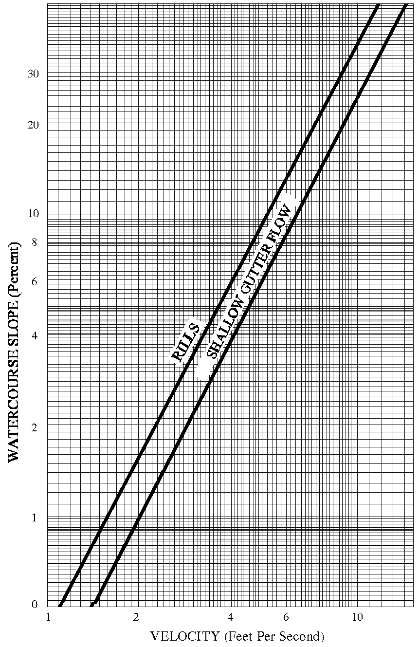
B.
Ditches (Rev. 7/29/02 - Ord. 02-52)
1.
The maximum ditch velocity allowed, without erosion protection, shall be governed by the following table:
Table A5 Maximum Ditch Velocity
2.
Ditch protection shall be determined by the following table:
Table A6 Ditch Protection
* Where watering, either natural or artificial, is available
3.
Outfall ditches and ditches not adjacent to a road shall be situated within a drainage easement of sufficient width to allow a 15 feet wide maintenance berm on one side and a five feet stability berm on the opposite side. The bottom width of an outfall ditch should be two feet wider than any culvert it serves. Side slopes of outfall ditches shall be 2:1 or flatter, unless ditches are paved. Drainage easements located on platted lots will be noted on the plat to be maintained by the property owner or other specified entity. Drainage easements will not serve as utility easements unless specifically approved by the County Engineer.
4.
Highway section ditches shall be a minimum of two feet below shoulder point elevation. Roadway centerline grades shall be higher than surrounding natural ground where wet conditions are encountered to prevent damage to base material. Ditch bottom width shall not be less than four feet.
5.
Roadside "V" or swale ditches may require storm sewer protection. Roadside "V" or swale ditches will be permitted only where soil conditions and grades are favorable.
C.
Culverts, Bridges and Pipes (Rev. 12-08-03 Ord. 03-69)
Pipe culverts under roads shall be reinforced concrete or pipe material approved by the County Engineer. The minimum diameter shall be 18 inches. When hydraulic conditions indicate the need for a head wall, a FDOT standard head wall will be required. Mitered pipe end sections shall be used in all locations where head walls create traffic hazards and may be substituted for standard end walls in other locations. Bridges and box culverts shall be designed to the FDOT Design Index.
D.
Side Drains
Side drains may be bituminous coated corrugated metal pipe, reinforced concrete pipe, aluminum pipe, or any other pipe material approved for the same use by FDOT. The minimum pipe size for local residential roads shall be 15 inches in diameter. For all other roads, the minimum pipe size shall be 18 inches in diameter.
E.
Seasonal High Water Table
1.
Soil borings will be taken and analyzed to a depth of six feet below natural ground or profile grade, whichever is the lower. Sufficient borings will be taken to determine the soil conditions and seasonal high water elevation evident throughout the proposed development. The depth to the high water table as shown in the Soil Survey of Polk County, Florida published by the Soil Conservation Service shall be taken into consideration in determining the seasonal high water elevation.
2.
Where the seasonal high ground water table or high water elevation of any detention/retention area adjacent to or in close proximity to the road is less than one and one-half feet below the proposed base, soil cement or cemented coquina base will be required in sections without highway ditch protection. In some areas, underdrains may be required in conjunction with the soil cement or cemented coquina base to protect the roadway from premature deterioration.
3.
Underdrains will be placed on the uphill side of the road (or on both sides, where needed) with the crown of the underdrain pipe four feet below natural ground or one-half feet below the base, whichever is the lower. The underdrain systems shall be designed by the engineer using the guideline specified below. Cleanouts, where required, shall be designed in accordance with Figure A5. Alternate underdrain designs shall be reviewed by the County Engineer.
F.
Underdrains
1.
The materials used shall conform to the following requirements:
a.
Filter fabric for use in underdrains shall conform to the following minimum properties:
b.
The filter fabric pipe wrap shall be an approved strong, tough, porous nylon, polyester, polypropylene, or other approved fabric which completely covers and is secured to the perforated plastic tubing pipe underdrain in such a way as to prevent infiltration of trench backfill material. The filter envelope shall weigh a minimum of four ounces (4 oz.) per square yard and shall retain soil particles larger than 212 microns (No. 70 sieve), when tested in accordance with ASTM D-1682, the grab strength (wet) of the filter wrap shall not be less than 100 lbs. and the grab elongation shall not be less than 60 percent. Storage and handling of filter envelope shall be in accordance with the manufacturer's recommendations. Torn or punctured filter wrap shall not be used.
c.
An example of a filter aggregate (fine aggregate) would be sand. Sand used for backfilling trenches under, around and over underdrain pipe shall consist of hard, durable, clean quartz sand and shall be reasonably well graded from coarse to fine and when tested by means of laboratory sieves, it shall meet the following requirements in percent of total weight.
Total Retained on:
d.
Examples of a filter aggregate (other) would be:
i.
When stone is used for filter aggregate it shall be composed clean, durable rock that is noncementous when exposed to water for extended periods and shall be so certified by a geotechnical engineer.
ii.
Slag shall be clean, tough and durable. It may be either air-cooled, blast-furnace slag or phosphate slag. It shall be reasonably uniform in density and quality and shall be so certified by a geotechnical engineer.
iii.
The gradations of stone and slag filter aggregates shall be designed and certified by a geotechnical engineer and approved by the County Engineer.
e.
Corrugated polyethylene tubing for use as underdrain shall conform to the requirements of AASHTO M-252. Polyethylene Tubing shall be delivered in lengths of 20 feet (minimum) and shall be fitted, prior to installation, with a filter fabric wrap (filter sock).
Figure A5. Underdrain Cleanout Detail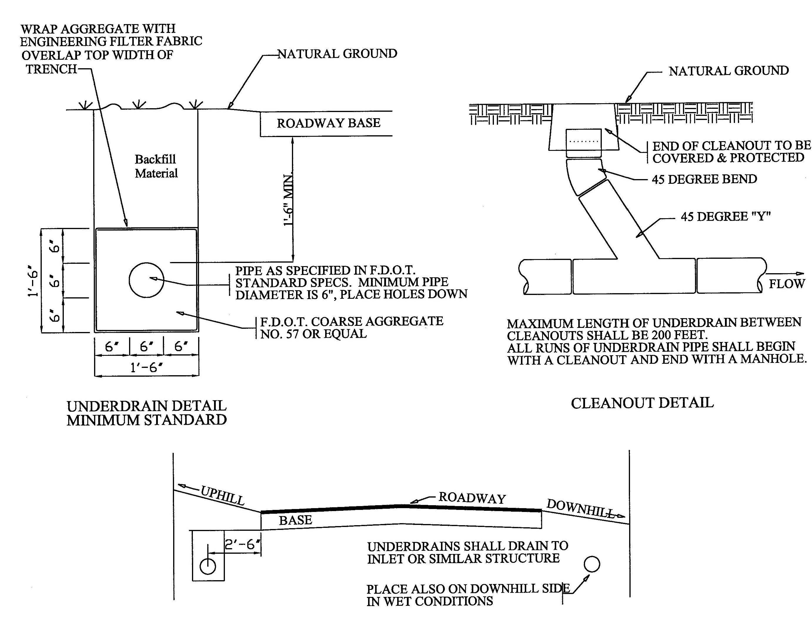
Section A103 - Road Design Requirements (Rev. 10/07/09 - Ord. 09-061)
A.
Stabilized Subgrade
1.
All road subgrade, where applicable, shall be stabilized to the required depth and required Florida bearing value, six inches outside the edge of base on each side of the road, and shoulders shall be stabilized six inches deep to Florida bearing value of 75. Where existing soils to be used in the road subgrade have the required bearing value, no additional stabilizing material need be added. Mixing shall be done to ensure uniformity whether or not additional material is added.
2.
The stabilizing material, if required, shall be high bearing value soil, clay-sand, limerock, shell or other material conforming to FDOT Standard Specifications.
B.
Base Course (Rev. 10/07/09 - Ord. 09-061)
The materials permitted as base course for flexible pavement are indicated in Table A-7 and shall meet the requirements of FDOT Standard Specifications for Road and Bridge Construction, 2000 Edition.
C.
Surface Course (Rev. 10/07/09 - Ord. 09-06; 10/12/05 - Ord. 05-062)
Any asphaltic concrete Type-S or Friction Course (FC) approved by the County (Marshall Mixes) or FDOT approved Superpave Mixes will be permitted. All asphalt mix designs submitted to the County for approval must be prepared by a certified materials testing laboratory, or by a Construction Training Qualification Program (CTQP) certified Asphalt Mix Designer. In either case all asphalt mix designs submitted to the County for approval shall be signed and sealed by a Professional Engineer (with the exception of Superpave Mixes). Only one type surface course will be permitted in each development or phase of a development. The allowable layer thickness for Type-S and friction courses asphalt mixes shall be as follows:
Type S-III = 1 inch
Type S-I = 1 ½ inches
FC- 3 = 1 inch
Recycled asphalt pavement (RAP) may be allowed for all layers, including the surface course except the friction course where only virgin material is permitted. The maximum percentage of RAP allowed for structural layers is 30 percent by weight of total aggregate. For each RAP stockpile, a stockpile number and composition data sheet, which includes the average gradation, asphalt content, and viscosity shall be provided.
D.
Flexible Pavement Road Design (Rev. 10/07/09 - Ord. 09-061; 2/22/06 - Ord. 06-11; Rev. 10/12/05 - Ord. 05-062)
1.
For collector and arterial roads, the method of determining road stabilized sub-grade, base and pavement thickness for standard typical sections are shown in Figures A6-A8. Typical road sections shall be designed using the structural number criterion, as set forth in Table. The minimum structure number shall be 3.0 as determined by layer coefficients. The typical road sections shall be used unless permitted otherwise by the County Engineer. The layer thickness for stabilized sub-grade shall be between 8 and 12 inches.
2.
For local roads, the minimum structural number shall be 2.29 as determined by the layer coefficients shown in Table A7. The layer thickness for stabilized sub-grade shall be between 8 -12 inches.
3.
The total layer coefficient allowed for the subgrade designed for local residential traffic shall not exceed the value assigned for eight inch thickness. The base material specified in Table A7 shall be used. The proposed typical section shall be shown on the plans and the structural number computation included under the typical section.
4.
Proposed local roads which are to accommodate commercial or industrial traffic shall be designed to a minimum structural number of 3.00 as determined by the layer of coefficients shown in Table A7.
5.
Table A7 is a suggested starting place for determining pavement layer type and material use based on previous general experience. Pavement sections differing from these guidelines are feasible when justified by local experience, construction procedure or appropriate supporting data. For cost comparison purposes, it may be desirable to use the thicknesses of ABC Types I, II, and III in increments of one inch.
E.
Rigid Pavement Design
Portland cement concrete pavement designed in accordance with the requirements of the American Concrete Paving Association Guide Specifications and Design Standards, contained in the "Municipal Concrete Paving Manual," or an equivalent specification may be approved by the County Engineer for construction.
F.
Access and Intersection Improvement (Rev. 10/07/09 - Ord. 09-061)
Access to residential or non-residential development shall be evaluated and improvements required as necessary. A Traffic Impact Study shall be required in accordance with Appendix C. Other factors shall be considered for access and or intersection improvements, such as existing traffic volume, traffic speed, vertical and horizontal alignments for sight clearance, bona fide future roadway improvements (e.g., C.I.P.), and other safety considerations. At a minimum, intersection improvement shall be required for residential development according to the number of dwellings indicated in Figures A9 through A17.
Table A7 Flexible Pavement Road Design Guidelines (Rev. 10/07/09 - Ord. 09-061)
Section A201 - Site Construction Standards
This Section establishes the minimum requirements for acceptable construction practices to be used on development projects throughout the County. The standards of the following sections are intended to promote the health, safety and welfare by providing a level of workmanship which is safe and durable.
Section A202 - Clearing and Grubbing
Clearing and grubbing shall consist of the removal and disposal of all timber, brush, stumps, roots, grass, weeds, sawdust, rubbish, and all other deleterious material resting on or protruding through the surface of the areas to be cleared.
A.
Road Construction and Embankment
In all areas of road construction and embankment, roots, and other deleterious materials shall be removed to a depth of not less than one foot below the subgrade.
B.
Stumps
Stumps shall be completely removed and plowed.
Section A203 - Excavation
This Section applies to excavation and embankment required for roads, ditches, channel changes and other works. Unless otherwise provided, this Section shall include all excavation, shaping, filling, sloping and finishing necessary for the construction, preparation, and the completion of all embankments, subgrades, shoulders, ditches, slopes, gutters, intersections, approaches, private entrances and other works, all in accordance with the required alignment, grade, and cross sections shown on the plans.
A.
Requirements
1.
While the excavation is being done and until the work is finally accepted, the contractor shall take the necessary steps to protect the work to prevent loss of material from the construction area due to the action of wind or water. During construction, the area shall be maintained in such condition that it will not constitute a hazard and will be well drained at all times.
a.
Where muck, rock, clay, phosphate slimes or other material is encountered within the limits of the construction area, the engineer of record shall direct that the material be excavated completely and backfilled with suitable materials. Other unsuitable plastic materials, identified as A-2-6, A-2-7, A-5, A-6, A-7 (AASHTO Designation), will be removed.
b.
The placing of embankments shall conform to the following:
i.
Embankments shall be constructed true to lines, grades and cross sections shown on the plans, within a 0.1 foot tolerance, unless otherwise specified on the approved plans.
ii.
Embankments shall be constructed of suitable materials placed in successive level layers not more than 12 inches in thickness, loose measure, for the full width and length of the embankment to the bottom of the stabilized subgrade and 98 percent of AASHTO T-180 Method "D" for the stabilized subgrade and base, and compacted to a minimum density of 100 percent of the maximum density value as determined by AASHTO T-99 Method "C."
c.
Shoulders, ditches and slopes shall conform to the following:
i.
When the work includes surfacing or paving, the earthwork, including the slopes and all drainage structures shall be substantially completed before the construction of the base course and pavement is started.
ii.
Where a stabilized shoulder is required, the earth shoulders, slopes, and side ditches shall be completed and shaped to a surface which is within 0.1 foot above or below the true surface shown on the plans, except that, adjacent to pavement, curb, or sidewalk, the shoulders shall be shaped to match the edge of the pavement, curb or sidewalk. The shoulder lines shall not vary more than 0.3 foot horizontally from the true lines shown on the plans.
2.
Subgrade shall be defined as that portion of the roadbed immediately below the base course or pavement including below the curb and gutter, the limits of which will ordinarily include those portions of the roadbed shown in the plans. The limits of the subgrade shall be considered to extend outward to six inches beyond the base. On roads where curbs are constructed, the subgrade shall extend to six inches beyond the back of curb as follows:
a.
The subgrade of limerock/clay shall:
i.
Stabilize to Limerock Bearing Ratio (LBR) 40
ii.
Compact to 98 percent of AASHTO T-180 Method "D"
b.
The subgrade of curbs shall:
i.
Stabilize to LBR 40
ii.
Compact to 98 percent of AASHTO T-180 Method "D" to include both sides of road.
c.
The stabilization material shall be high bearing value soil, sand-clay, limerock, shell, or other material approved by the engineer of record and shall meet the physical requirements of FDOT Standard Specifications Section 914-2.
d.
The surface of the subgrade shall conform to the lines and grades as defined on the construction plans to a tolerance of 0.05 feet.
e.
Tests for the subgrade bearing capacity, thickness and compaction shall be spaced at a maximum of 600 feet apart. Locations for the tests shall be chosen by the engineer of record at locations where weakness is suspected and shall be staggered to the left, right, and on the centerline of the road. Testing results shall be submitted by the testing engineer of record to the County Engineer. When, in the judgment of the County Engineer conditions warrant additional testing to assure compliance with specifications, the engineer of record will be advised, and arrangements will be made by the engineer of record for the additional testing. All tests shall be the responsibility of the engineer of record. A minimum of three tests per road is required (one if road is less than 600 feet). Testing for stabilized shoulders shall include both sides of the road.
f.
After the subgrade has been completed as specified above, the contractor shall maintain it free from ruts, depressions and any damage resulting from the hauling or handling of materials, equipment, and tools. It shall be the contractor's responsibility to maintain the required density until the subsequent base or pavement is in place. Such responsibility shall include any repairs, or replacement, of curb, gutter, or sidewalk, which might become necessary in order to recompact the subgrade/subbase in the event of underwash or other damage occurring to the previously compacted subgrade/subbase. Ditches and drains shall be constructed and maintained along the completed subgrade section.
(Ord. No. 2025-007, § 7, 1-21-2025)
Section A205 - Limerock Base
This Section applies to the construction of a base course composed of limerock. It shall be constructed on a prepared subgrade in accordance with these specifications and in conformity with the lines, grades, notes, and typical cross sections shown on the plans.
A.
Materials
The material used shall conform with the requirements as specified in the FDOT Standard Specifications.
B.
Equipment
This work may be performed with any machine, combination of machines, or equipment that will produce the specified results.
C.
Transporting Limerock
The limerock shall be transported to the point where it is to be used, over rock previously placed and dumped on the end of the preceding spread.
D.
Spreading Limerock
The limerock shall be spread uniformly. All segregated areas of fine or coarse rock shall be removed and replaced with well-grading rock. When the specified compacted thickness of the base is greater than six inches, the base shall be constructed in two courses. The thickness of the first course shall be approximately one-half the total thickness of the finished base, or enough additional to bear the weight of the construction equipment without disturbing the subgrade.
E.
Compacting and Finishing Base
1.
For double-course base, the first course shall be bladed, if necessary, to secure a uniform surface, and shall be compacted to the specified density immediately prior to spreading the second course. No other finishing of this course is required.
2.
After spreading is completed, the entire surface shall be scarified and shaped so as to produce the exact grade and cross section after compaction. For double-course bases, this scarifying shall extend to a depth sufficient to penetrate slightly the surface of the first course.
3.
Proper moisture condition shall be maintained uniformly throughout the material during the compaction operation. The material shall be compacted to a minimum density of 98 percent of the maximum density obtainable under AASHTO T-180 Method "D". Where the base is being constructed in one course and the specified thickness is more than six inches, the density specified above shall be obtained in both the bottom half and top half of the base. During final compacting operations, if blading of any areas is necessary to obtain the true grade and cross section, the compacting operations for such areas shall be completed prior to making the density determinations on the finished base.
4.
The surface shall be "hard-planed" with a grader immediately prior to the application of the prime coat to remove the thin-glazed or cemented surface, leaving a granular or porous condition that will allow free penetration of the prime material. The materials planed from the base shall be removed from the base area.
5.
If, at any time, subgrade material should become mixed with the base course material, the contractor shall excavate and remove the mixture, reshape and compact the subgrade, and replace the materials removed with clean base material, which shall be shaped and compacted as specified above.
F.
Prime/Curing
When the limerock has been finished as specified herein, it shall be protected by the application of a bituminous coating. The bituminous material shall be applied as soon as possible after the completion of finishing operations. The Prime/Curing material shall be in accordance with Section A204.
G.
Testing Surface
The finished surface of the base course shall be checked with a template cut to the required cross section and with a straight edge of 15 feet laid parallel to the centerline of the road or other approved testing devices. All irregularities greater than 1/4 inch shall be corrected by scarifying and removing or adding rock, as may be required, after which the affected areas shall be re-compacted and retested, as specified herein. In testing the surface, measurements will not be taken in small holes caused by individual pieces of rock having been pulled out by the grader.
H.
Tests
At least one of each of the following tests shall be made on every project by the engineer of record, or his representative:
1.
Modified Proctor Maximum Density Determination Tests
2.
Intervals of 300 feet, minimum of three density determinations per road.
3.
Intervals of 300 feet, with a minimum of two per road. Locations for the tests shall be chosen by the engineer of record at locations where weakness is suspected and shall be staggered to the left, right, and on the centerline of the road. Testing results shall be submitted by the testing engineer to the County Engineer. When, in the judgment of the County Engineer conditions warrant additional testing to assure compliance with specifications, the engineer of record will be advised and arrangements will be made by the engineer of record for the additional testing.
I.
Deficiencies
1.
If deficiency in the density occurs, the base shall be reworked to 100 feet on either side of the deficiency and re-compacted until the density tests conform to these specifications.
2.
Any deficiencies greater than one-half inch shall be completely reworked to conform to the original line and grade and specifications as shown on the original plans.
Section A206 - Prime and Tack Coats for Base Courses
This Section applies to the application of bituminous material, on a previously prepared base, in accordance with these specifications and in conformity with the lines, grades, dimensions, and notes shown on the plans.
A.
Materials
The materials used shall be as follows:
1.
A prime coat consisting of cutback asphalt, Grade RC-SS-1, SS-1H, special MS-Emulsion, diluted at the ratio of 6 parts emulsified asphalt to 4 parts water.
2.
A tack coat consisting of cutback asphalt, Grade RC-70, asphalt cement, viscosity grades AC-20 or AC-30, emulsified asphalt, Grade RS-2, SS-1, SS-1H special MS-Emulsion, diluted at the ratio of 6 parts emulsified asphalt to 4 parts water.
3.
For the prime and tack coat, any one of the specified bituminous materials may be used at the option of the contractor, unless a specific type and grade is called for on the plans which has been approved by the County Engineer.
4.
This work may be performed with any machine, combination of machines, or equipment that will produce the specified results.
5.
Before any bituminous material is applied, all loose material, dust, and foreign material which might prevent proper bond with existing surface shall be removed for the full width of the application. Particular care shall be taken to clean the outer edges of the strip to be treated in order to ensure that the prime or tack coat will adhere. Where the prime or tack coat is applied adjacent to curb and gutter or valley gutter, such concrete surfaced are to be protected and kept free of bituminous material.
6.
No bituminous material shall be applied when the temperature of the air is less than 40°F. in the shade, or when the weather conditions or the condition of the existing surface is unsuitable.
7.
Application of the prime coat shall be as follows:
a.
The surface to be primed shall be clean and free of standing water.
b.
For limerock bases, the glazed finish shall have been removed leaving a granular or porous condition that will allow free penetration of bituminous material. The temperature of the prime material shall be between 100°F. and 150°F. The actual temperature will be that which will ensure uniform distribution. The material shall be applied by means of a pressure distributor. The amount of bituminous material applied shall be not less than 0.10 gallon per square yard for limerock base and not less than 0.20 gallon per square yard for sand clay, soil cement, or shell base, not greater than 0.25 gallon per square yard.
c.
The prime coat shall be applied only when the base meets the specified density requirements and the moisture content in the top half of the base does not exceed 90 percent of the optimum moisture of the base material. At the time of priming, the base shall be firm, unyielding, and in such condition that no undue distortion will occur.
d.
A light uniform application of clean sand shall be applied prior to opening the primed base to traffic, in which case the sand shall be rolled with a traffic roller. If warranted by traffic conditions, the application shall be made only on one-half of the width of the base at one time, care being taken to secure the correct amount of bituminous material at the joint.
e.
The base shall be sufficiently moist in order to obtain maximum penetration of the asphalt.
8.
Where a bituminous surface is to be laid and a tack coat is required, it shall be applied as follows:
a.
On newly constructed base courses, the application of the tack coat shall follow the application of the prime coat, immediately prior to placing the wearing surface, when the tack coat is required.
b.
In general, a tack coat will not be required on primed bases, except in areas which have become excessively dirty and cannot be cleaned in areas where the prime has cured and lost bonding effect, or where the prime coat has worn away.
c.
The tack coat shall be applied with a pressure distributor. The bituminous material shall be heated to a suitable consistency as designed. The bituminous material shall be applied at the rate between 0.02 gallon and 0.08 gallon per square yard.
d.
The tack coat shall be applied sufficiently in advance of the laying of the wearing surface to permit drying but shall not be applied so far in advance or over such an area as to lose its adhesiveness as a result of being covered with dust or other foreign material and shall be kept free from traffic until the wearing surface is laid.
Section A207 - Asphaltic Concrete Surface Course
This Section applies to the application of asphaltic concrete surface course composed of a mixture of aggregates and, if necessary, mineral filler and asphalt cement to produce the desired stability hereinafter described, properly laid upon a prepared base in accordance with these specifications and in conformity with the lines, grades, thickness and typical cross section shown on the plans. This work shall include the conditioning of the existing surface or base as described in section A206.
A.
Asphaltic Concrete Mixes (Rev. 10/07/09 - Ord. 09-061)
Marshall Mixes
1.
The plant and methods of operation for preparing all plant mixed hot bituminous mixtures for surface courses and bases shall comply with the FDOT Standard Specifications for Section 320 of the Road and Bridge Construction, 2000 Edition, or as provided in Section A207-A below.
2.
All asphaltic concrete mixes shall meet FDOT Standard Specifications for Marshall Design properties and standard design thickness and be approved by the County Engineer. The minimum design thickness for Type S-III and FC-3 shall be 1 inch and 1 ½ inches for Type S-I.
Hot Mix Asphalt (Superpave (SP)
1.
General: Construct a Hot Mix Asphalt (HMA) pavement based on the type of work specified in the Plans and the Asphalt Work Categories as defined below. Meet the applicable requirements for plants, equipment, and construction requirements as defined below. Use a HMA mix that meets the requirements of this specification.
2.
Asphalt Work Mix Categories: Construction of Hot Mix Asphalt Pavement will fall into one of the following work categories:
a.
Asphalt Work Category 1: Includes the construction of bike paths and other non vehicular traveled surfaces.
b.
Asphalt Work Category 2: Includes the construction of new HMA turn lanes, paved shoulders, parking lots, and other non-mainline pavement locations. Also, includes the construction of new mainline HMA pavement lanes, milling and resurfacing.
Table A8 Allowable Hot Mix Types (Rev. 10/07/09 - Ord. 09-061)
3.
Mix Types: Use the appropriate HMA mix as shown in Table A8
4.
Gradation Classification: HMA mixes are classified as either coarse or fine, depending on the overall gradation of the mixture. Coarse and fine mixes are defined in this Section. Use only fine mixes.
The equivalent AASHTO nominal maximum aggregate size Superpave mixes are as follows:
Type SP-9.5 = 9.5 mm
Type SP-12.5 = 12.5 mm
Type SP-19.0 = 9.0 mm
5.
Thickness: The total pavement thickness of the HMA pavement will be based on a specified spread rate or plan thickness as shown in the Plans. Before paving, propose a spread rate or thickness for each individual layer meeting the requirements of this specification, which when combined with other layers (as applicable) will equal the plan spread rate or thickness. When the total pavement thickness is specified as plan thickness, the plan thickness and individual layer thickness will be converted to spread rate using the following equation:
Spread rate (lbs/yd
2
) = t x G
mm
x 43.3
where: t = Thickness (in.) (Plan thickness or individual layer thickness)
G
mm
= Maximum specific gravity from the mix design
For target purposes only, spread rate calculations shall be rounded to the nearest whole number.
a.
Layer Thicknesses: Unless otherwise called for in the Plans, the allowable layer thicknesses for HMA mixtures are as follows:
Type SP-9.5 = 1 inch
Type SP-12.5 = 1 1/2 inches
Type SP-19.0 = 2 inches
b.
Additional Requirements: The following requirements also apply to HMA mixtures:
i.
When construction includes the paving of adjacent shoulders (:S5 feet wide), the layer thickness for the upper pavement layer and shoulder shall be the same and paved in a single pass, unless otherwise called for in the Plans.
ii.
For overbuild layers, use the minimum and maximum layer thicknesses as specified above unless called for differently in the Plans. On variable thickness overbuild layers, the minimum allowable thickness may be reduced by 1/2 inch, and the maximum allowable thickness may be increased by 1/2 inch, unless called for differently in the Plans.
6.
Weight of Mixture: Equip the asphalt plant with or provide HMA from a plant with an electronic weigh system that: has an automatic printout, is certified every six months by an approved certified scale technician. Weigh all plant produced hot mix asphalt on the electronic weigh system, regardless of the method of measurement for payment. Print the delivery ticket with an original and at least one copy. Delivery ticket must have mix design number and mix type printed on it. Furnish the original to the Engineer at the plant and one copy to the County Engineer at the paving site.
B.
Materials (Rev. 10/07/09 - Ord. 09-061)
1.
Superpave Asphalt Binder: Use an asphalt binder from the FDOT's Qualified Products List (QPL) meeting FDOT Section 916.
2.
Aggregate: Aggregate supplier shall certify that the aggregate meets FDOT requirements Section 901, Coarse Aggregate, and 902, Fine Aggregate.
3.
Reclaimed Asphalt Pavement (RAP) Material:
a.
General Requirements: RAP may be used as a component of the asphalt mixture if approved by the County Engineer. Usage of RAP is subject to the following requirements:
i.
Limit the amount of RAP material used in the mix to a maximum of 30 percent by weight of total aggregate. Up to 40 percent RAP may be used when additional testing is performed or approved by the County Engineer.
ii.
Provide stockpiled RAP material that is reasonably consistent in characteristics and contains no aggregate particles which are soft or conglomerates of fines. RAP stockpiles must be FDOT certified or approved by the County.
iii.
Provide RAP material having a minimum average asphalt content of 4.0 percent by weight of total mix. The Engineer may sample the stockpile to verify that this requirement is met.
iv.
Use a grizzly or grid over the RAP cold bin, in-line roller crusher, screen, or other suitable means to prevent oversized RAP material from showing up in the completed recycle mixture. If oversized RAP material appears in the completed recycle mix, take the appropriate corrective action immediately. If the appropriate corrective actions are not immediately taken, plant operations must stop.
b.
Material Characterization: Assume responsibility for establishing the asphalt binder content, gradation, viscosity and bulk specific gravity (Gsb) of the RAP material based on a representative sampling of the material.
c.
Asphalt Binder for Mixes with RAP: Select the appropriate asphalt binder grade based on Table 2. Maintain the viscosity of the recycled mixture within the range of 5,000 to 15,000 poises.
Table A9: Asphalt Binder Grade for Mixes Containing RAP
C.
Composition of Mixture (Rev. 10/07/09 - Ord. 09-061)
1.
General: The asphalt mixture shall be composed using a combination of aggregates, mineral filler, if required, and asphalt binder material. The aggregate fractions shall be sized, graded, and combined to meet the grading and physical properties of the mix design.
2.
Mix Design:
a.
General: The asphalt mixture shall be designed in accordance with AASHTO R35-04, except as noted herein. A current FDOT approved mix design shall be used. A copy of the current mix design must be provided to the County Engineer.
b.
Mixture Gradation Requirements: Combine the aggregates in proportions that will produce an asphalt mixture meeting all of the requirements defined in this specification and conform to the gradation requirements at design as defined in AASHTO M323-04, Table 3. Aggregates from various sources may be combined.
i.
Mixture Gradation Classification: Plot the combined mixture gradation on an FHWA 0.45 Power Gradation Chart. Include the Control Points from AASHTO M323-04, Table-3, as well as the Primary Control Sieve (PCS) Control Point from AASHTO M323-04, Table 4. Fine mixes are defined as having a gradation that passes above or through the primary control sieve control point. Use only fine mixes.
c.
Gyratory Compaction: Compact the design mixture in accordance with AASHTO T312-04. Use the number of gyrations as defined in AASHTO R35-04, Table 1.
d.
Design Criteria: Meet the requirements for nominal maximum aggregate size as defined in AASHTO M323-04, as well as for relative density, VMA, VFA, and dust-to-binder ratio as specified in AASHTO M323-04, Table 6.
e.
Moisture Susceptibility: In lieu of moisture susceptibility testing, add a liquid anti-stripping agent from the Department's Qualified Products List. Add 0.5% liquid anti-stripping agent by weight of binder.
f.
Additional Information: In addition to the requirements listed above, provide the following information on each mix design:
i.
The design traffic level and the design number of gyrations (Ndesign).
ii.
The source and description of the materials to be used.
iii.
The FDOT source number and the FDOT product code of the aggregate components furnished from an FDOT approved source (if required).
iv.
The gradation and proportions of the raw materials as intended to be combined in the paving mixture. The gradation of the component materials shall be representative of the material at the time of use. Compensate for any change in aggregate gradation caused by handling and processing as necessary.
v.
A single percentage of the combined mineral aggregate passing each specified sieve. Degradation of the aggregate due to processing (particularly material passing the No. 200 sieve) should be accounted for and identified.
vi.
The bulk specific gravity (Gsb) value for each individual aggregate and RAP component.
vii.
A single percentage of asphalt binder by weight of total mix intended to be incorporated in the completed mixture, shown to the nearest 0.1 percent.
viii.
A target temperature at which the mixture is to be discharged from the plant and a target roadway temperature. Do not exceed a target temperature of 330°F for modified asphalts and 315°F for unmodified asphalts.
ix.
Provide the physical properties achieved at four different asphalt binder contents. One shall be at the optimum asphalt content, and must conform to all specified physical requirements.
x.
The name of the Mix Designer.
xi.
The ignition oven calibration factor.
D.
Contractor Quality Control (Rev. 10/07/09 - Ord. 09-061)
Assume full responsibility for controlling all operations and processes such that the requirements of these Specifications are met at all times. Perform any tests necessary at the plant and roadway for quality control purposes.
E.
Mechanical Spreading & Screening Equipment (Rev. 10/07/09 - Ord. 09-061)
1.
Bituminous pavers shall be self-contained, self-propelled and equipped with a receiving and disbursing hopper. The hopper shall be equipped with a conveyer distribution system to place the mixture uniformly in front of the screed.
2.
The paver shall also be equipped with a heated mechanical screed or strike-off assembly. The screed or strike-off shall be capable of adjustment to regulate the depth of material spread and produce a finished surface of the required evenness and texture, without tearing, shoving, or gouging the mixture.
3.
Power boxes will not be acceptable.
F.
Equipment (Rev. 10/07/09 - Ord. 09-061)
1.
For all asphalt courses, with the exception of open-graded friction mixes, placed with mechanical spreading and finishing equipment in pavement widths of 20 feet or greater, the paving machine shall be equipped with automatic longitudinal screed controls of either the skid type or the traveling stringline type. The length of the skid or traveling stringline shall be at least 25 feet. On the final layer of Base, Overbuild and Structural Courses, and for Friction Courses, the joint matcher shall be used in lieu of the skid or traveling stringline on all passes after the initial pass.
2.
When the paving machine is equipped with pneumatic tires, the Engineer may require that the tires be ballasted.
3.
Paving machines used on main roads shall be a screed width greater than eight feet. On widening strips, cross-overs, or ramps, paving machines having a screed width of eight feet or less may be used.
4.
Steel-wheeled rollers shall be of the tandem type. For the seal rolling, these rollers shall weigh between five and 12 tons and for the final rolling; they shall weigh between eight and 12 tons.
5.
Traffic rollers shall be of the self-propelled, pneumatic-tired type, equipped with at least seven smooth-treated, low-pressure tires, with the tire pressure maintained between 50 and 55 pounds. They shall weigh between six and ten tons. The use of wobble-wheeled rollers will not be permitted.
6.
Adhesion of the mixture to the wheels of all rollers will not be permitted. The use of fuel oil or other petroleum distillates to prevent adhesion will not be permitted. No method shall be used which results in water being sprinkled directly onto the mixture.
7.
Trucks used to transport the mix shall be of tight construction, which will prevent the loss of material and the excessive loss of heat. Each truck shall have a tarpaulin or other waterproof cover, mounted in such a manner that the entire load can be covered. When in place, the waterproof cover shall overlap all sides and be capable of being tied down. The trucks shall also be equipped with chains on the tail gates to limit the size of the opening while unloading into the paver.
8.
The contractor will be required to furnish a suitable saw or drill for obtaining the required density cores.
9.
The necessary hand tools such as rakes and shovels, and a suitable means for keeping them clean, shall be provided.
G.
Reserved
H.
Reserved
I.
Superpave Mixes Construction Methods (Rev. 10/07/09 - Ord. 09-061)
1.
Weather Limitations: Do not transport asphalt mix from the plant to the roadway unless all weather conditions are suitable for the laying operations.
2.
Limitations of Laying Operations:
a.
General: Spread the mixture only when the surface upon which it is to be placed has been previously prepared, is intact, firm, and properly cured, and is dry.
b.
Surface Temperature: Spread the mixture only when the pavement surface temperature in the shade and away from artificial heat is at least 40ºF for layers greater than 1 inch (100 lb/yd 2 ) in thickness and at least 45ºF for layers 1 inch (100 lb/yd 2 ) or less in thickness (this includes leveling courses). The minimum temperature requirement for leveling courses with a spread rate of 50 lb/yd 2 or less is 50ºF.
c.
A pre-paving meeting has been held with Polk County.
3.
Mix Temperature: Heat and combine the ingredients of the mix in such a manner as to produce a mixture with a temperature at the plant and at the roadway, within a range of ±30ºF from the established plant mixing temperature as shown on the mix design. Reject all loads outside of this range.
4.
Transportation of the Mixture: Transport the mix in trucks of tight construction which prevents the loss of material and excessive loss of heat. Vehicles will be cleaned of all foreign material. After cleaning, thinly coat the inside surface of the truck bodies with soapy water or an asphalt release agent as needed to prevent the mixture from adhering to the beds. Do not allow excess liquid to pond in the truck body. Do not use diesel fuel or any other hazardous or environmentally detrimental material as a coating for the inside surface of the truck body. Provide each truck with a tarpaulin or waterproof cover mounted in such a manner that it can cover the entire load when required. Cover each load during transportation, but fully tarp and strap down loads produced in cool weather or when there is a high probability of rain.
5.
Preparation of Surfaces Prior to Paving:
The following steps shall be followed prior to paving:
a.
Cleaning: Clean the surface of all loose and deleterious material by the use of power brooms or blowers, supplemented by hand brooming where necessary.
b.
Patching and Leveling Courses: Where the HMA is to be placed on an existing pavement which is irregular, wherever the plans indicate, or if directed by the Engineer, bring the existing surface to proper grade and cross- section by the application of patching or leveling courses.
c.
Application over Surface Treatment: Where an asphalt mix is to be placed over a surface treatment, sweep and dispose of all loose material from the paving area.
d.
Tack Coat: Apply a tack coat on existing pavement structures with a pressure distributor that is to be overlaid with an asphalt mix and between successive layers of all asphalt mixes, unless directed otherwise by the Engineer. In areas inaccessible by a pressure distributor, use of a wand or hand tacking is permissible. Use a tack coat product meeting FDOT specifications. Use an emulsified tack coat spread rate of 0.02 to 0.08 gal/sy or as specified by the Engineer.
6.
Paving:
a.
Alignment of Edges: With the exception of pavements placed adjacent to curb and gutter or other true edges, place all pavements by the stringline method to obtain an accurate, uniform alignment of the pavement edge. Control the unsupported pavement edge to ensure that it will not deviate more than ± 1.5 inches from the stringline.
b.
Rain and Surface Conditions: Immediately cease transportation of asphalt mixtures from the plant when rain begins at the roadway. Do not place asphalt mixtures while rain is falling, or when there is water on the surface to be covered. Once the rain has stopped and water has been removed from the tacked surface to the satisfaction of the Engineer (no puddles or ponded water) and the temperature of the mixture caught in transit still meets the requirements as specified in Section A207, the Contractor may then place the mixture caught in transit.
c.
Checking Depth of Layer: Check the depth of each layer at frequent intervals, and make adjustments when the thickness exceeds the allowable tolerance. When making an adjustment, allow the paving machine to travel a minimum distance of 32 feet to stabilize before the second check is made to determine the effects of the adjustment.
d.
Hand Spreading: In limited areas where the use of an asphalt paver is impossible or impracticable, spread and finish the mixture by hand and compact thoroughly.
e.
Spreading and Finishing: Provide mechanical spreading and screeding equipment of an approved type that is self-propelled and can be steered.
Equip it with a receiving and distribution hopper and a mechanical screed. Use a mechanical screed capable of adjustment to regulate the depth of material spread and to produce the desired cross-section. Upon arrival, dump the mixture in the approved paver, and immediately spread and strike-off the mixture to the full width required, and to such loose depth for each course that, when the work is completed, the required weight of mixture per square yard, or the specified thickness, is secured. Carry a uniform amount of mixture ahead of the screed at all times.
f.
Thickness of Layers: Construct each course of Type SP mixtures in layers of the thickness as outlined Section A207.
7.
Leveling Courses:
a.
Patching Depressions: Before spreading any leveling course, fill all depressions in the existing surface more than 1 inch deep by spot patching with leveling course mixture, and compact thoroughly.
b.
Spreading Leveling Courses: Place all courses of leveling with an asphalt paver or by the use of two motor graders, one being equipped with a spreader box. Other types of leveling devices may be used upon approval by the Engineer.
c.
Rate of Application: When using Type SP-9.5 (fine graded) for leveling, do not allow the average spread of a layer to be less than 50 lb/yd 2 or more than 75 lb/yd 2 . The quantity of mix for leveling shown in the plans represents the average for the entire project; however, the Contractor may vary the rate of application throughout the project as directed by the Engineer. When leveling in connection with base widening, the Engineer may require placing all the leveling mix prior to the widening operation.
8.
Compaction: For each paving or leveling train in operation, furnish a separate set of rollers, with their operators. When density testing for acceptance is required (Asphalt Work Category 2) select equipment, sequence, and coverage of rolling to meet the specified density requirement. Regardless of the rolling procedure used, complete the final rolling before the surface temperature of the pavement drops to the extent that effective compaction may not be achieved or the rollers begin to damage the pavement. When density testing for acceptance is not required (Asphalt Work Category 1), use a rolling pattern approved by the Engineer. Use hand tamps or other satisfactory means to compact areas which are inaccessible to a roller, such as areas adjacent to curbs, headers, gutters, bridges, manholes, structures, etc.
9.
Joints.
a.
Transverse Joints: Construct smooth transverse joints, which are within 3/16 inch of a true longitudinal profile when measured with a 15 foot manual straightedge.
b.
Longitudinal Joints: For all layers of pavement except the leveling course, place each layer so that longitudinal construction joints are offset 6 to 12 inches laterally between successive layers. Do not construct longitudinal joints in the wheelpaths. The Engineer may waive this requirement where offsetting is not feasible due to the sequence of construction.
10.
Surface Requirements: Construct a smooth pavement with good surface texture and the proper cross-slope.
a.
Texture of the Finished Surface of Paving Layers: Produce a finished surface of uniform texture and compaction with no pulled, torn, raveled, crushed or loosened portions and free of segregation, bleeding, flushing, sand streaks, sand spots, or ripples. Correct any area of the surface that does not meet the foregoing requirements in accordance with this Section.
b.
Cross Slope: Construct a pavement surface with cross slopes in compliance with the requirements of the Plans. Contractor is not responsible for bird baths if design cross slope is less than 2%.
c.
Pavement Smoothness: Construct a smooth pavement meeting the requirements of this Specification. Furnish a 15 foot manual and a 15 foot rolling straightedge meeting the requirements of FM 5-509. Make them available at the job site at all times during paving operations for Asphalt Work Category 2 and make them available upon request of the Engineer for Asphalt Work Category 1.
i.
Asphalt Work Category 2:
(a)
Acceptance Testing: Straightedge the final Type SP structural layer and friction course layer with a rolling straightedge. Test all pavement lanes where the width is constant using a rolling straightedge and document all deficiencies on a form approved by the Engineer. Notify the Engineer of the location and time of all straightedge testing a minimum of 48 hours before beginning testing.
(b)
Rolling Straightedge Exceptions: Testing with the rolling straightedge will not be required in the following areas: shoulders, intersections, tapers, crossovers, parking lots and similar areas. In addition, testing with the rolling straightedge will not be performed on the following areas when they are less than 250 feet in length: turn lanes, acceleration/deceleration lanes and side streets. However, correct any individual surface irregularity in these areas that deviates from the plan grade in excess of 3/8 inch as determined by a 15 foot manual straightedge, and that the Engineer deems to be objectionable, in accordance with Section A207. The Engineer may waive or modify straightedging requirements if no milling, leveling, overbuild or underlying structural layer was placed on the project and the underlying layer was determined to be exceptionally irregular.
(c)
Final Type SP Structural Layer: Straightedge the final Type SP structural layer with a rolling straightedge behind the final roller of the paving train. Correct all deficiencies in excess of 3/16 inch in accordance with Section A207, and retest the corrected areas.
(d)
Friction Course Layer: At the completion of all paving operations, straightedge the friction course. Correct all deficiencies in excess of 3/16 inch in accordance with this Section. Retest all corrected areas.
ii.
Asphalt Work Category 1: If required by the Engineer, straightedge the final structural layer with a rolling straightedge, either behind the final roller of the paving train or as a separate operation. Correct all deficiencies in excess of 5/16 inch in accordance with Section A207. Retest all corrected areas. If the Engineer determines that the deficiencies on a bicycle path or other areas due to field geometrical conditions, the Engineer will waive corrections with no deduction to the pay item quantity.
d.
Correcting Unacceptable Pavement:
i.
General: Correct all areas of unacceptable pavement.
ii.
Structural Layers: Correct deficiencies in the Type SP structural layer by one of the following methods:
(a)
Remove and replace the full depth of the layer, extending a minimum of 50 feet on either side of the defective area for the full width of the paving lane, or as determined by the County Engineer, or his or her designee.
(b)
Mill the pavement surface to a depth and width that is adequate to remove the deficiency. (This option only applies if the structural layer is not the final surface layer.)
iii.
Fiction Course: Correct deficiencies in the friction course layer by removing and replacing the full depth of the layer, extending a minimum of 50 feet on either side of the defective area for the full width of the paving lane. Corrections may be waived if approved by the County Engineer.
J.
Superpave Mix Acceptance Tests (Rev. 10/07/09 - Ord. 09-061)
1.
General: The asphalt mixture will be accepted based on the Asphalt Work Category as defined below:
a.
Asphalt Work Category 1 - Certification by the Contractor as defined in Section A207.
b.
Asphalt Work Category 2 - Quality control for acceptance testing by the Contractor and verification testing at the discretion of the County Engineer as defined in Section A207.
2.
Certification by the Contractor: On Asphalt Work Category 1 construction, the County Engineer will accept the mix on the basis of visual inspection. Submit a Notarized Certification of Specification Compliance letter on company letterhead to the County Engineer stating that all material produced and placed on the project was in substantial compliance with the Specifications. The County Engineer may run independent tests to determine the acceptability of the material.
3.
Quality Control Testing by the Contractor and Acceptance Testing by the County Engineer: On Asphalt Work Category 2, perform quality control testing as described in Section A207. In addition, the County Engineer will accept the mixture at the plant with respect to air voids, gradation (P-8 and P-200) and asphalt binder content (Pb). The mixture will be accepted on the roadway with respect to density. The County Engineer may sample and test the material as described in Section A207 with the contractor retaining a split of the sample. The County Engineer may randomly obtain at least one set of samples per day. Assure that the asphalt content, gradation and density test results meet the criteria in Table 3. Material failing to meet these acceptance criteria will be addressed as directed by the County Engineer.
a.
Quality Control Sampling and Testing Requirements: Perform quality control testing at a frequency of minimum of 1 per mix type per day up to 500 tons, a second test required for production over 500 tons per day. If multiple jobs producing from same mix-test once and attach to results each project. Obtain the samples in accordance with FDOT Method FM 1-T 168 and retain an additional split sample for the County Engineer. Test the mixture at the plant for air voids, gradation (P-8 and P-200) and asphalt binder content (Pb). Test the mixture on the roadway for density using six-inch diameter roadway cores, with no cores located closer than 1 foot to joint or unsupported edge. Trim and test roadway cores for Gmb and patch core holes within 72 hours. Obtain cores at a minimum frequency of 3 cores per 500 tons or less, unless otherwise directed by the County Engineer. If tonnage exceeds 500 tons, take additional cores at the frequency of 1 per 150 tons. Determine the asphalt content of the mixture in accordance with FM 5-563. Determine the gradation of the recovered aggregate in accordance with FM 1-T 030. Determine the roadway density in accordance with FM 1-T 166. The minimum roadway density will be based on the percent of the maximum specific gravity (Gmm) from the accepted quality control test results representing that day's production. Roadway density testing will not be required in certain situations as described in Section A207. Assure that the air voids, asphalt content, gradation and density test results meet the criteria in Table A10. Forward copies of the test results to the County Engineer.
Table A10 Quality Control and Acceptance Values
b.
Acceptance Testing Exceptions: Density testing for acceptance will not be performed on widening strips or shoulders with a width of 5 feet or less, variable thickness overbuild courses, leveling courses, first lift of asphalt base course placed on subgrade, irregular shaped hand worked areas, miscellaneous asphalt pavement, or any course with a specified thickness less than 1 inch or a specified spread rate less than 100 lbs/sy. In addition, density testing for acceptance will not be performed on the following areas when they are less than 250 feet in length: crossovers, turning lanes, acceleration lanes, deceleration lanes, or ramps. Compact these courses in accordance with a standard rolling procedure approved by the County Engineer. In the event that the rolling procedure deviates from the approved procedure, placement of the mix will be stopped.
K.
Finished Surface Requirements (Rev. 10/07/09 - Ord. 09-061)
For the purpose of testing the finished surface, the contractor provides a rolling straight edge of 15 feet and standard template cut to the true cross section of the road. These shall be available at all times during construction so that the County may check the finish surface. The contractor shall provide and designate some employee whose duty it is to use the straight edge and template in checking all rolled surface under the direction of the County. Vertical measurement from a string line between curbs or edge of pavement to determined crown may be accepted as an alternate. The finished surface shall be such that it will not vary more than 3/16 inch from the rolling straight edge of 15 feet applied parallel to the centerline of the pavement and shall be of uniform texture and compaction. The surface shall have no pulled, or or loosened portions and shall be free from segregation, sand streaks, sand spots, or ripples. Irregularities of the surface exceeding the above requirements shall be corrected by the contractor who has the option of selecting one of the following methods:
1.
If correction is made by removing and replacing the pavement, the removal must be for the full depth of the course and extend at least 50 feet on either side of the defective area, for the full width of the paving lane.
2.
If correction is made by overlaying, the overlay shall cover the length of the defective area and taper uniformly to a feather-edge thickness at a minimum distance of 50 feet on either side of the defective area. The overlay shall extend full width of the road. Care shall be taken to maintain the specified cross slope. The mix used for the overlay may be adjusted as necessary for this purpose by the County Engineer. Overlaying will not be permitted when the finished pavement surface is a friction course or abuts concrete curbs.
3.
For courses which will not be the final pavement surface, correction of minor straightedge efficiencies by methods other than specified above may be approved by the County Engineer.
(Ord. No. 2025-007, § 8, 1-21-2025)
Section A208 - Portland Cement Concrete Pavement
Rigid pavement consists of constructing a specified Portland Cement Concrete Paving on a prepared subgrade. The utilities and other items in and beneath the road must be properly coordinated with the construction of rigid pavement to avoid all conflicts. The work to be done shall include the furnishing of all supervision, labor, materials, equipment and incidentals necessary for the proposed rigid pavement construction in accordance with the approved drawings and specifications.
A.
Subgrade Preparation for Rigid Pavement
1.
General requirements for subgrade preparation for rigid pavement are as follows.
a.
The bottom of the excavation for the pavement or top of the earth fill will be known as the pavement subgrade and shall conform to the lines, grade, and cross-sections shown on the plans.
b.
Prior to placing the concrete, the subgrade shall be tested for conformity with the cross-section shown on the plans.
c.
If necessary, material shall be removed or added as required to bring all portions of the subgrade to the correct elevation. Concrete shall not be placed on any portion of the subgrade which has not been tested for correct elevation. The subgrade shall be cleared of all loose material. At any time that trucks, construction equipment or slipforming machines cause rutting or displacement of the subgrade materials, the subgrade shall be reshaped and compacted. The subgrade shall be in a moist condition at the time the concrete is placed.
2.
The top six inches shall be composed of well drained granular soils that are predominantly sandy, mixed with no more silt or clay than required to obtain a Florida Bearing value of 35 plus or minus 5 and be compacted to 95 percent of maximum density in accordance with AASHTO T-180.
3.
Testing of the subgrade shall conform to the following:
a.
Tests for subgrade stabilization shall be located no more than 400 feet apart and shall be staggered to the left, right, and on the centerline of the road. Test reports for subgrade stabilization shall be submitted to the County Engineer by the engineer of record for review and approval prior to paving.
b.
When in the judgment of the County Engineer conditions warrant additional testing, the engineer of record will be advised that additional tests will be required and the extent of such additional tests.
B.
Materials, Proportioning and Construction for Rigid Pavements
The materials and proportioning shall be in accordance with ACI Standard 318, latest edition. All construction procedures shall be in accordance with FDOT Standard Specifications.
1.
All concrete shall have a minimum compressive strength of 3,000 (pci) psi at 28 days. Conformance to strength requirements shall be determined by American Concrete Institute Standard 318, Sections 4.8.2.3 and 4.8.3.
2.
Slump shall consist of the following:
a.
The mixture shall contain no more water than is necessary to produce concrete which is workable and plastic. The minimum slump necessary to place the concrete satisfactorily shall be used. Slumps should be maintained so as not to exceed four and one-half inches for nonvibrated placement and not to exceed 5 inches for vibrated placement.
b.
The design mix shall be submitted to the County Engineer for approval prior to paving.
C.
Equipment
1.
The pavement shall be placed to lines and grades established by the engineer. The edges of pavement shall be vertical to the subgrade and forms will be sufficient to support mechanical equipment.
2.
All plants must be certified by the FDOT.
3.
The plant shall be in accordance with the FDOT Standard Specifications. The trucks used to transport the concrete shall be so constructed to prohibit segregation of the mix. All plants must be certified by the FDOT.
4.
All equipment used in the placement of concrete pavements shall conform to Section 350-3 of the FDOT Standard Specifications.
D.
Mixing and Placing for Rigid Pavement
1.
Concrete pavement shall be constructed on the prepared subgrade in accordance with these Regulations and in conformity with the lines, grades, thickness, and typical cross-sections shown on the construction plans.
2.
Concrete may be transported any distance providing it is discharged on the grade with the slump within the required slump range and meets concrete time limit requirements. If additional water is required to maintain the specified slump of concrete transported in truck mixers, it may be added with the permission of the County Engineer. In this case, a minimum of 25 additional revolutions of the mixer drum at designed mixing speed shall be required before discharging of the concrete.
3.
The length of time that the concrete can be held in the truck shall conform to the following:
a.
Air temperature 45°F to 80°F - 90 minutes maximum
b.
Air temperature over 80°F with a retarder added to the mix - 90 minutes maximum
c.
Air temperature over 80°F without a retarder added to the mix - 60 minutes maximum
d.
The maximum temperature of the concrete at the time of placing shall be 95°F.
4.
The concrete shall be deposited on the grade in such a manner as to require as little rehandling as possible. It shall be deposited in successive batches in a continuous operation. The concrete shall be consolidated by suitable means so as to preclude the formation of voids or honeycomb pockets.
5.
Concrete shall only be placed when the temperature is at least 40°F in the shade and rising. Any concrete damaged by frost or freezing action shall be removed and replaced.
6.
Finishing requirements are as follows:
a.
The concrete shall be struck-off, consolidated, and finished with mechanical equipment in such a manner that after final finishing, it shall conform to the pavement cross-section shown on the construction plans. Hand finishing will be permitted in narrow width, areas, or irregular dimensions, and in the event of breakdown of the mechanical equipment only to finish the concrete already deposited on the grade.
b.
The final surface of the pavement shall have uniform, skid-resistant texture. The method of texturing shall be approved by the County Engineer and may require changes in the final finishing procedure as required to produce the desired final surface texture. A burlap drag or transverse broom finish is recommended for local and collector roads. Arterial and rural roads may require an overlapping stiff bristled broom or steel comb finish at the County Engineer's option.
c.
The contractor shall always have materials available to protect the surface of the plastic concrete against rain. Areas of the pavement surface that exhibit a smooth sandy appearance after the rain ceases shall be textured to these areas before applying the membrane curing material. Areas that have suffered some surface erosion and have coarse aggregate exposed shall be reworked by hand methods or with the finishing machine when the form paving method is used. Fresh concrete containing the same materials and properties as the pavement concrete shall be added to maintain an adequate supply in front of the screeds or machine to assure replacement of the concrete eroded from the surface. The surface shall then be textured and cured as specified.
d.
If pavement edges have been severely eroded and the concrete has not set, the edges shall be repaired by setting side forms and replacing eroded concrete. After the side forms are set, fresh concrete shall be placed and finished prior to texturing and curing. After the pavement has hardened, remedial work shall not be permitted until after the curing period has terminated.
7.
Curing for rigid pavements shall be as follows:
a.
After finishing operations have been completed and immediately after the free water has left the surface, the surface of the slab and, for slipformed pavements, the sides of the slab shall be coated and sealed with a uniform layer of membrane curing compound applied at the rate of not less than one gallon per 200 square feet of surface. When the forms are removed, curing compound shall be applied to the sides of the slab. Areas in which the curing membrane is damaged within a period of three days shall be re-sprayed with curing compound.
b.
Curing compound may be omitted when, in conjunction with protection of pavement from inclement weather, a polyethylene film or other acceptable material is applied over the pavement and maintained intact for three days.
c.
Rigid concrete pavement with excessive, uncontrolled cracks will not be accepted. Shrinkage cracks must be avoided. Uncontrolled cracks 1/8 inch or larger in width shall be repaired. One of the following repair methods shall be used:
i.
Removal and replacement;
ii.
Widen with power router and fill with an approved joint sealant; or
iii.
Epoxy grout injection.
d.
The County Engineer shall determine which cracks are to be repaired and the method to be used.
8.
Joints in rigid pavements shall be as follows:
a.
Transverse and longitudinal joints shall be constructed to a maximum spacing of 15 feet. Transverse joints shall extend the entire width of the pavement and through the curbs. Joints must be sawed after the concrete has hardened and conform to the standard detail within the Standard Indexes.
b.
Sawing of joints shall begin four to six hours after placing or as soon as the concrete has hardened sufficiently to permit sawing without excessive raveling and before uncontrolled cracking occurs. If necessary, the sawing operations shall be carried on both day and night, regardless of weather conditions.
c.
Longitudinal joints may be construction joints at the County Engineer's option. Transverse construction joints shall be installed whenever the placing of concrete is suspended a sufficient length of time for the concrete to begin to harden.
d.
Joints shall be sealed, if required, before the pavement is exposed to traffic, including construction traffic. Prior to sealing, all foreign material shall be removed from the joints and the joints shall be thoroughly dry.
9.
Final acceptance for rigid pavements shall be as follows:
a.
Before the pavement will be considered for acceptance all items shall be complete in accordance with the construction plans and these Regulations. Equipment, surplus materials, and construction debris shall be removed from the project.
b.
The pavement shall be closed to traffic after the concrete is placed until it reaches a compressive strength of 2500 psi under ordinary field conditions. This does not include the sawing and sealing equipment or other light miscellaneous equipment.
c.
Concrete pavement shall have a 28 day compressive strength of 3000 psi. Portland Cement Concrete control for slump testing and concrete cylinder samples and testing is required and shall be in accordance with AASHTO and ASTM Specifications. Test reports shall be submitted to the County Engineer by the engineer of record for review.
Section A209 - Culverts and Storm Sewers
This Section applies to furnishing and installing culverts and storm sewers with appurtenances in conformance with the specifications hereinafter described and of the sizes and dimensions shown on the plans. Only concrete pipe shall be permitted under road pavement.
A.
Pipe (Rev. 10/07/09 - Ord. 09-061)
1.
Concrete pipe shall meet the following requirements:
a.
Concrete pipe shall be of first quality, conforming to ASTM C-76 for round pipe and ASTM C-507 for elliptical pipe. The size and class shall be as shown on the plans. Joints for all round pipe shall be sealed by the use of round rubber gaskets and shall conform to the applicable provisions of ASTM C-361.
b.
Joints for elliptical pipe may be a tongue and groove type and sealed with a preformed gasket material (Ram-Nek or equal). The preformed gasket shall be applied to form a continuous gasket around the leading edges of both the primed tongue and groove in a manner that when the pipes are joined, the entire annular space will be filled with gasket material and there will be evidence of squeeze out of gasket material for the entire internal and external circumference of the joint.
c.
Elliptical concrete pipe joints shall be wrapped with filter fabric conforming to Section A103-A11. Filter fabric material shall extend a minimum of three feet on both sides of the joint and shall overlap a minimum of two feet at the top of the joint.
2.
Corrugated metal pipe shall meet the following requirements:
a.
Bituminous coated metal pipe shall conform to the current AASHTO Standard Specification M-190. Corrugated aluminum alloy pipe shall conform to the current AASHTO Standard Specification M-196. All corrugated metal pipe installed shall have a continuous helical lock seam or a continuous welded helical seam. Riveted seam, spot welded seams, or non-helical corrugated metal pipe shall not be installed under this specification. Aluminum culverts can be specified if the soil Ph is between five and one-half and eight and one-half and soil resistivity is 1500 ohm-cm or greater certified by a licensed geotechnical engineer. If soils fall outside of these ranges, prior approval of storm drainage materials shall be obtained from the County Engineer.
b.
The ends of all corrugated metal pipe shall be recorrugated and the pipe supplied with a metal banding system. The metal band system shall have a minimum width of one foot and a rubber gasket or approved equal, which shall fit snugly in the space between the recorrugated end and metal band.
c.
The jointing system shall prevent soil infiltrating into the pipe. All joints under and within six feet of the edge of a pavement shall be wrapped with filter fabrics. The material shall extend a minimum of three feet on both sides of the joint and shall have an overlap of two feet on the top of the joint.
d.
Banding of the filter fabric may be required at the discretion of the County Engineer.
e.
Corrugated steel pipe and corrugated aluminum pipe shall conform to the minimum gages of metal set forth in the attached schedule. All accessories and hardware shall conform to Section 430 of the FDOT Standard Specifications.
f.
Alternative storm sewer materials may be utilized, such as aluminized steel per Section 943 of the FDOT Standard Specifications, Polyvinyl Chloride (PVC) in accordance with ASTM F-949 and Section 948-1.7 of the FDOT Standard Specifications or other FDOT approved materials.
3.
All pipe shall be carefully laid, true to the lines and grades as shown on the plans. All pipe shall be laid "in the dry" unless specifically authorized otherwise by the County Engineer.
a.
Concrete pipe shall meet the following requirements:
i.
The joint shall be thoroughly lubricated and assembled according to the manufacturer's recommendations so that the maximum width of the joint opening shall not exceed the standards as set forth in FDOT 430-7.2.
ii.
If, while making the joint, the gasket comes loose and can be seen through the exterior joint recess when joint is pulled up within one inch of closure, the dry pipe shall be removed and the joint remade.
b.
Trenching shall conform to the latest OSHA requirements.
c.
The metal band shall be drawn together in conformance with the manufacturer's specification. The rubber gasket shall be uniformly compressed around the circumference of the pipe. Re-corrugated ends and bands damaged shall be rejected and removed from the construction site.
d.
Pipe inlet/manhole joints shall conform to the following:
i.
The joints of pipe and inlet/manhole shall be carefully cleaned and completely filled with non-shrink mortar applied and cured in accordance with the manufacturer's recommendations. An asphaltic mastic material shall be applied 12 inches in width from the joint around the exterior of the pipe and on the exterior wall of the inlet/manhole. A continuous 24 inch width of filter fabric shall be wrapped around each joint and shall have an overlap of two feet on the top of the pipe-inlet/manhole joint.
ii.
The filter fabric shall be thoroughly bonded to the asphaltic mastic material. Filter fabric shall conform to Section A211.
iii.
All pipe shall be carefully laid, true to the lines and grades as shown on the plans. All pipe shall be laid "in the dry" unless specifically authorized otherwise by the County Engineer.
e.
Backfilling shall conform to the following:
i.
Backfilling shall progress as rapidly as the construction and testing of the work will permit. All backfill material shall be suitable and free of deleterious material. The initial backfill shall be carefully deposited on both sides of the pipe at the same time and uniformly compacted around the barrel of the pipe until enough has been placed to provide a cover of one foot above the crown of the pipe. In no case shall backfill material be placed in the trench in a manner that will cause shock to or unequal pressure on the pipe. The backfill shall be placed and compacted to 100 percent of maximum density as determined by AASHTO T-99 to the bottom of the stabilized subgrade and 98 percent of T-180 for the stabilized subgrade and base under and within six feet of the traveled way and under other existing hard surfaced or previously compacted areas. In all areas except for those stated, compaction must equal a firmness approximately equal to that of the soil adjacent, or as directed by the County Engineer.
ii.
Flowable fill is an acceptable method.
iii.
Under no condition is construction debris or concrete, to be included with the backfill.
f.
Where the nature of the foundation materials is of poor supporting value, the foundation material shall be replaced with sand or other material, or as approved by the County Engineer. The foundation material shall be consolidated by mechanical methods to specified densities.
g.
Tests shall be performed in accordance with the following:
i.
Compaction tests shall be in accordance with Section 125-8 of the FDOT Standard Specifications for Road and Bridge Construction, latest edition. The County Engineer may determine that more compaction tests are required to certify the installation depending on field conditions. The locations of compaction tests within the trench shall be in conformance with the following schedule:
(a)
One test at 6" intervals from the bottom of the pipe to an elevation one foot above the crown of the pipe (contractor may use 12" lifts if densities can be obtained in 12" lifts);
(b)
One test for each one foot of backfill placed one foot above the crown of the pipe to subgrade elevation; and,
(c)
Cross drain culverts shall have a minimum of two density tests per lift.
ii.
All pipe runs shall be video recorded by a remote camera in the presence of a County representative. The video shall be provided to the County Engineer in DVD format with a narrative for each pipe run.
4.
A pipe certification shall be submitted to the County Engineer for all pipe furnished or as approved by the County Engineer. The certification shall be signed and sealed by a registered professional engineer for the State of Florida. The certification shall state that the pipe installed and materials supplied comply with all applicable specifications contained herein. The substitution of corrugated metal pipe for concrete pipe or concrete pipe for corrugated metal pipe requires the written authorization of the County Engineer.
Section A210 - Inlets and Manholes
This Section applies to the construction inlets and manholes. These structures shall be constructed of either clay brick, Portland Cement concrete and reinforcing steel with the necessary metal frames and gratings and shall be constructed in conformity with the detailed plans and in accordance with these specifications.
A.
Materials
1.
Concrete shall have a minimum compressive strength of 3000 psi at 28 days. The mortar for masonry shall be of Portland Cement and sand mixed in the proportions of one part cement to three parts of sand.
2.
At the option of the contractor, high early strength cement may be used.
B.
Forms
Forms shall be built true to line and grade, braced in a substantial and unyielding manner and so designed and constructed that they may be removed without injury to the concrete.
C.
Placing and Curing Concrete
The concrete shall be placed in the form to the depth shown on the plans and thoroughly tamped and spaded. After the concrete has hardened sufficiently, it shall be covered with suitable material and kept moist for a period of three days or longer, if necessary, and shall be protected in a satisfactory manner from the elements until thoroughly cured.
D.
Masonry Construction
All clay brick used shall conform to the current ASTM Designation C-55 Grade P-11. All masonry construction of inlets and manholes will be of cylindrical shape.
E.
Pre-Cast Inlets and Manholes
Pre-Cast manholes, inlets and junction boxes shall be in accordance with FDOT Standard Specifications.
F.
Placing Pipes
The inlet and outlet pipes shall be flush with the inside face of the wall. The joints of pipe and inlet/manhole shall be carefully cleaned and completely filled with nonshrink mortar applied and cured in accordance with the manufacturer's recommendations. An asphaltic mastic material shall be applied 12 inches in width from the joint around the exterior of the pipe and on the exterior wall of the inlet/manhole. A continuous 24 inch width of filter fabric shall be wrapped around each pipe-inlet/manhole joint and shall have an overlap of two feet on the top of the pipe-inlet/manhole joint. The filter fabric shall be thoroughly bonded to the asphaltic mastic material. Filter fabric shall conform to Section A211.
G.
Flow Channels
A flow channel shall be formed in the invert of all inlets, manholes and junction boxes and shall extend to the spring line of the pipe.
Section A211 - Underdrains
This Section applies to the construction of underdrains.
A.
Pipe Diameter
Underdrain pipe shall have a minimum diameter of six inches, unless otherwise approved by the County Engineer.
B.
Excavation Trench
1.
The trench shall be excavated carefully, to such depth as is required to permit the pipe to be laid to the grade desired, and to the dimensions shown in the plans.
2.
The underdrain trench shall be constructed in a dry condition. This shall be accomplished by the use of a well point system or other positive dewatering method.
C.
Placing the Filter Fabric
After the trench has been excavated, the filter fabric shall be rolled out over the trench and walked into the trench. Care shall be taken to prevent the excavated material from entering the trench after the fabric has been installed.
D.
Laying the Pipe
1.
After the filter fabric has been placed in the trench, approximately three inches of filter aggregate shall be placed in the trench.
2.
The pipe shall be bedded firmly in the filter aggregate to the correct line and grade. The upper end of the run of pipe shall terminate at a drainage structure or underdrain clean-out to prevent any filter aggregate from entering the pipe.
3.
All lateral connections to underdrains shall be made at approved drainage structures. Cleanouts or approved drainage structures shall be located along all underdrain systems. The maximum spacing of cleanouts or structures shall be 350 feet.
E.
Placing and Compacting Filter Aggregate
After the pipe has been laid to grade, the pipe shall be firmly held in place by mechanical means while the filter aggregate is placed to a maximum height of five inches plus one inch (compacted) above the top of the pipe. After the first lift is placed and compacted to the satisfaction of the County Engineer, the remainder of the filter aggregate shall be placed. The excavation of the trench, the placement of the filter fabric, the installation of the pipe and the placement and compaction of the first lift of filter aggregate shall be accomplished in a single continuous operation. Special care shall be taken to avoid displacement or damage to the pipe or filter fabric.
F.
Backfill Above Filter Aggregate
After the filter aggregate has been placed 12 inches above the pipe the filter fabric shall be lapped the full width of the trench from both sides. The portion of the trench above the filter aggregate shall be filled with fine filter aggregate which shall be placed and tamped in layers not thicker than 12 inches to the existing grade.
G.
Certification
Upon completion of the project, the engineer of record shall provide to the County Engineer, a certification that all materials installed and construction on the underdrain system complies with the approved design or approved design with defined exception.
H.
Acceptance of Underdrains
The County Engineer may require a video inspection of underdrain systems and correction of any deficiencies before approval.
Section A212 - Sidewalks and Concrete Curb
This Section applies to the construction of curb, curb and gutter, valley gutter, or sidewalks of Portland Cement Concrete. Such work shall be constructed in accordance with these specifications and in conformity with the lines, grades, dimensions, and notes shown on the plans. Should the contractor so elect, he may use a curb machine.
A.
Materials
Unless otherwise shown on the plans, concrete shall be Class I.
B.
Forms
1.
Forms for this work shall be made of either wood or metal. They shall be straight, free from warp or bends, and of sufficient strength, when staked, to resist the pressure of the concrete without springing.
2.
Forms shall have a depth equal to the plan dimensions for the depth of the concrete being deposited against them.
C.
Construction Methods
1.
Excavation shall be made to the required depth and the subgrade or base upon which the curb, curb and gutter, valley gutter, and sidewalks are to be set shall be compacted as specified.
2.
The concrete shall be placed in the forms to the depth specified and tamped and spaded until mortar entirely covers its surface. The top of the curb or gutter shall be floated smooth and the edges rounded to the radius shown on the plans.
D.
Joints
1.
Where metal templates are used for joint construction, the curb and curb and gutter shall be constructed in uniform sections ten feet in length, except where shorter sections are necessary for closures, but no section shall be less than four feet.
2.
At the option of the contractor, the sections may be formed by the use of dummy joints (either formed or sawed) or by the use of sheet metal templates. If sheet metal templates are used, they shall be of the dimensions and shall be set to the lines shown on the plans. The templates shall be held firmly during the placing of the concrete and shall be left in place until the concrete has set sufficiently to hold its shape, but shall be removed while the forms are still in place.
3.
Dummy joints shall be spaced at intervals of ten feet for curb and intervals of five feet for sidewalks. They shall be 1/4 the depth of the concrete. Expansion joints shall be placed in sidewalks at a maximum of 30 feet at driveways, sidewalk intersection, all inlets, all radius points, all points where operations cease for any considerable time (such as the end of the day's run).
E.
Finishing
1.
The gutter or flow-line section or curb shall be tested with a straight of ten feet edge laid parallel to the centerline of the road and while the concrete is still plastic. Irregularities in excess of 1/4 inch shall be immediately removed.
2.
Repair of minor defects shall meet the following requirements:
a.
The forms shall be removed within 24 hours after the concrete has been placed, and minor defects then filled with mortar composed of one part Portland Cement and two parts fine aggregate.
b.
Plastering will not be permitted on the face of the curb, and any rejected curb, curb and gutter, or valley gutter shall be removed and replaced.
3.
The top of the curb and the face from the top to eight inches below, shall be given a surface finish while the concrete is still green. In general, only a brush finish will be required.
F.
Curing
All curbs shall be covered with suitable material and kept moist for a period of three days, or longer if necessary, and shall be protected in a satisfactory manner from damage by the elements or other causes until acceptance of the work. If curing compound is used, moistening is not required.
G.
Backfilling and Compaction
1.
After the concrete has set sufficiently, but not later than three days after pouring, the spaces in front and back of the curb shall be refilled to the required elevation with suitable material, which shall be placed and thoroughly compacted in layers not thicker than six inches.
2.
Where bases are to be constructed adjacent to the curb, the concrete shall be properly backfilled and shall set for a period of not less than three days before any base material is placed against it.
H.
Requirements for Machine-Laying
As a specified requirement for machine-laid curb and gutter, contraction joints shall be sawed unless an alternate method of constructing them is approved in advance. Joints shall be provided at intervals of ten feet, except where shorter intervals are required for closure, but no joints shall be sawed or constructed at intervals of less than four feet.
Section A213 - Seeding and Mulching
This Section applies to the seeding and mulching of road shoulders, ditches, embankments, and other areas left barren by construction to establish a dense stand of grass.
A.
Materials
The grass seed shall be common Bermuda and Bahia. In addition, brown top millet will be included during summer months and annual rye in the winter months. The mulch shall consist of thoroughly shredded straw or hay. All seed shall meet the requirements of the State Department of Agriculture. The chemical composition of the fertilizer shall be 12-8-8 or other chemical composition specified in the plans.
B.
Construction Methods
1.
Construction methods shall be in accordance with the FDOT Standard Specifications, except as noted herein.
2.
Seed will be applied at not less than the following rate:
Permanent type: 100 lbs. per acre
Quick growing type: 30 lbs. per acre
3.
Fertilizer shall be applied at the rate of 500 lbs. per acre.
4.
A hydro-mulch process meeting the application rates provided above may be used.
C.
Sodding
Sodding shall be in accordance with the FDOT Standard Specifications. Sod destroyed by construction will be replaced with existing type of grass.
Section A214 - Traffic Control
All projects and work on existing roads shall have a traffic control plan. Traffic control or maintenance of traffic plan shall be submitted for County review, prior to the pre-construction meeting. All work shall be executed under the established plan and department-approved procedures, and conform to the Manual of Uniform Traffic Control Devices adopted by FDOT.
A.
Pavement Markings
This Section applies to the installation of pavement markings as shown on the plans in accordance with these specifications.
B.
Materials
All paint, reflective pavement markers, and glass spheres shall conform to FDOT Standard Specifications.
C.
Installation
Painted traffic markings, reflective pavement markers, and thermoplastic traffic markings shall be installed in conformance with FDOT Standard Specifications. Thermoplastic traffic markings shall not be applied to asphalt pavements within 30 days of the placement of the asphalt pavement.
Section A215 - Restoration of Existing Right-of-Way
Restoration of existing right-of-way disturbed by the installation of utilities or adjacent construction projects shall be in conformance with the special conditions of the permit and this Section.
A.
Traffic Control
Traffic control shall be in conformance with the Manual on Uniform Traffic Control Devices and the FDOT Road and Traffic Design Standards.
B.
Excavation
Excavation shall be in accordance with Section A203.
C.
Utility Foundations
Where the nature of the foundation materials is of poor supporting value, the foundation material shall be replaced with sand or other material, or as approved by the County Engineer. The foundation material shall be consolidated by mechanical methods to specified densities.
D.
Backfill and Compaction to Sub-Grade or Existing Ground
Backfilling shall progress as rapidly as the construction and testing of the work will permit. All backfill material shall be suitable and free of deleterious material. The initial backfill shall be carefully deposited on both sides of the utility at the same time and uniformly compacted around the utility until enough has been placed to provide a cover of one foot above the utility, at which time a density test shall be conducted. Material shall then be placed and compacted in one foot lifts above the utility. In no case shall backfill material be placed in the trench in a manner that will cause shock to, or unequal pressure on, the utility. Under no conditions is construction debris or concrete to be included with the backfill.
E.
Compaction (Rev. 10/07/09 - Ord. 09-061)
1.
Compaction density testing shall begin as stated above, and shall be tested for each one foot increment, above that point. The last test shall be taken at existing ground level, or top of the subgrade/subbase, whichever applies.
2.
Testing shall conform to the following:
a.
Under and within six feet of the traveled way and under other existing hard surfaced or previously compacted areas. Compaction must equal 100 percent of maximum density as determined by AASHTO T-99 to the bottom of the stabilized subgrade and 98 percent of maximum density as determined by AASHTO T-180 for the stabilized subgrade and base.
b.
In all areas except for the above, compaction must be equal to a firmness approximately equal to that of the soil adjacent.
3.
Density tests for determination of the specific backfill, base or compaction shall be under the direction of an engineer licensed in the State of Florida at the expense of the permittee, and reports submitted to the County Engineer.
4.
Flowable fill is an acceptable backfill.
F.
Base and Pavement Restoration
1.
Pavement or road surfaces cut or damaged shall be replaced with the same type material that existed at the time of removal, or as approved by the County Engineer, to like or better condition than existing prior to the construction.
2.
Where existing pavement is to be removed, the surface shall be mechanical saw cut prior to trench excavation, leaving a uniform and straight edge, with minimum disturbance to the remaining adjacent surfacing.
3.
The base, during open cut restoration, shall be brought up to the grade of the existing pavement, and shall consist of a minimum thickness of eight inches of 3000 psi high early strength concrete.
4.
The minimum width of the concrete shall be 12 inches each side of the open cut in addition to the width of the open cut as shown on the Standard Road Open Cut Detail.
5.
In advance of pouring the concrete base, during final restoration, the existing asphalt surface shall be mechanically sawed straight and clean.
6.
Immediately following the specified backfilling, compaction, testing and base construction, the final surface restoration shall be commenced in accordance with the applicable detail, and as approved on the permit. Asphalt material shall be replaced with the same type of material that existed at the time of removal and shall be a minimum of one inch thick, or as approved by the County Engineer.
G.
Unpaved Road Restoration
The top 12 inches of the excavation shall be stabilized with a mixture of clay and sand to a condition equal to or better than existing surface. Compaction density of this layer shall equal 98 percent of maximum density as determined by AASHTO Specification T-180.
H.
Seeding and Mulching
Seeding and mulching shall be in accordance with Section A213 of these specifications.
Section A216 - Utility Appurtenances in Roadways (Added 10/07/09 - Ord. 09-061; 10/12/05 - Ord. 05-062 as Amended 2/22/06 by Ord. 06-11)
A.
Location
A pressurized pipe such as sanitary force main, gas pipe, storm water force main, reclaimed water main, and potable water main, except for a pipe that is four inches in diameter or less, shall be constructed outside of roadway pavement a minimum setback distance of six (6) feet from the outside edge of the travel lane or four (4) feet from outside face of curb in a roadway with a curb and gutter, to closest outside face of the utility pipeline. Utility access panels shall be placed outside of roadway pavement at a minimum distance of six feet from the outside edge of roadway travel lanes or accessory lane, and driveways.
If placement of a pressure pipe does not meet the setback requirement and is not installed under roadway travel lanes (or curb and gutter if applicable), the pipeline excavation, and backfill in six inches lifts shall be in accordance with subsections 125-4 and 125-8 of the latest edition of Florida Department of Transportation Standard Specifications for Road and Bridge Construction, Section 125 Excavation for Structures and Pipe.
A pressure pipe that is proposed under a roadway pavement (or curb and gutter if applicable) shall be evaluated and approved/denied by the utility purveyor on a case-by-case basis, with the approval of the County Engineer. The pressure pipeline backfill and compaction tests shall be at six inches lift. The pipeline excavation and backfill under a proposed roadway shall also be in accordance with subsections 125-4 and 125-8 of the latest edition of Florida Department of Transportation Standard Specifications for Road and Bridge Construction. In all cases, any pressure and gravity pipe approved for construction under a roadway shall be constructed at least 36 inches below the bottom of the road base. A pressure pipeline proposed under and across an existing roadway pavement shall be installed by directional bore or jack and bore in accordance with applicable latest edition of FDOT Section 555 or Section 556.
B.
Backfill for Structures and Tests (Rev. 10/07/09 - Ord. 09-061)
Backfill placed under and around a structure such as a utility manhole or a drainage inlet located within the right-of-way of an existing or proposed road shall be compacted and tests performed under and on at least two opposite sides of the structure, and on at least one side for every curb inlet. One compaction test shall be taken directly under the structure and all side tests shall be taken at a minimum vertical frequency of every 12 inches. Compaction test report certified by a licensed geotechnical engineer must be submitted to the County Engineer within two weeks of the test performed and prior to placement of roadway paving structural courses if pipe work and backfill are performed within the right-of-way of an existing or proposed road.
Compaction tests shall also be performed for backfill for each facility or utility structure including manholes and drainage inlets, within a proposed roadway or improvement to existing roadway such as acceleration and deceleration lanes.
Backfill placed under and within six feet of the edge of a road travel or accessory lane and under other existing paved surface or previously compacted areas shall be placed and compacted to 100 percent of maximum density as determined by AASHTO T-99 to the bottom of the stabilized subgrade and 98 percent of AASHTO T-180 for the stabilized subgrade and base. Compaction of backfill in other locations shall be in accordance with Section A203, Appendix A.
C.
Finished Grade Requirements (Rev. 10/07/09 - Ord. 09-061)
Appurtenances for storm sewer, sanitary sewer, water and other utility system, such as manhole covers, valve box covers, etc., which are located within an existing or proposed pavement such as a roadway or sidewalk shall be at grade with the final pavement surface. Acceptable tolerance shall be 3/8 inch. A deficiency found shall be corrected either by adjusting the appurtenance or the placement of asphalt in an asphalt roadway for a length extending from the appurtenance at a slope of 50:1; or in a manner recommended by engineer of record and approved by the County Engineer.
Section A301 - Commercial, Industrial and Multi-Family (Revised 10/07/09 - Ord. 09-061)
This section is provided to establish minimum standards to be used designing and constructing non-residential horizontal infrastructure, specifically regarding transportation and drainage features of the development.
Section A302 - Purpose and Intent (Rev. 10/07/09 - Ord. 09-061)
This Section establishes the minimum engineering design standards applicable to all Commercial, Industrial and Multi-Family developments. The standards are intended to promote the public health, safety and welfare by ensuring the improvements are designed to adequately provide for transportation and drainage features of the development.
Section A303 - Drainage Design Requirements (Rev. 10/07/09 - Ord. 09-061)
The storm sewer design shall follow the requirements of Section A102 of this Appendix. However, the Engineer of Record may use other design storms and materials for those facilities on site as deemed appropriate for the level of risk acceptable to the developer and approved by the County Engineer.
Section A304 - Road and Parking Area Design Requirements (Rev. 10/07/09 - Ord. 09-061)
The road design for local and collector roads within non-residential developments that serve as access to parking areas and driveway aisles shall be in accordance with Section A103 of this Appendix. Those service roads, parking areas and driveway aisles that will not be dedicated to Polk County, and are required to be paved in accordance with Section 709, shall be designed according to the following criteria.
A.
Stabilized Subgrade (Rev. 10/07/09 - Ord. 09-061)
All road subgrade, where applicable, shall be stabilized to the required depth and required bearing value as shown on the approved plans. The Engineer of Record shall determine the depth required to meet the structural number of the pavement design.
B.
Base Course (Rev. 10/07/09 - Ord. 09-061)
The base course shall be compacted to the depth and bearing value shown on the approved plans. The Engineer of Record shall determine the depth required to meet the structural number of the pavement design.
C.
Surface Course (Rev. 10/07/09 - Ord. 09-061)
1.
Any asphaltic concrete surface course meeting the requirements of Section A207 of this Appendix, or as approved by the County Engineer, will be permitted. Minimum thickness for all asphaltic surface courses shall be one inch with construction tolerance of 0.25 inch. The maximum content of recycled asphalt pavement (RAP) in the mix shall be 40% by weight.
2.
Other alternative pavements may be utilized as a surface course conforming to the manufacturer specifications as approved by the County Engineer.
D.
Flexible Pavement Road Design (Rev. 10/07/09 - Ord. 09-061)
Typical Pavement Sections shall be determined by the structural number criterion. The minimum structure number shall be 1.58 as determined by layer coefficients shown in Table A7.
E.
Rigid Pavement Design (Rev. 10/07/09 - Ord. 09-061)
Portland cement concrete pavement, designed in accordance with the requirements of the American Concrete Paving Association Guide Specifications and Design Standards, contained in the "Municipal Concrete Paving Manual," or an equivalent specification may be approved by the County Engineer for construction.
Section A401 - Site Construction Standards for Non-Residential Development (Rev. 10/07/09 - Ord. 09-061)
This Section establishes the minimum requirements for acceptable construction practices to be used on non-residential development projects throughout the County. The standards of the following sections are intended to promote the health, safety and welfare by providing a level of workmanship which is safe and durable.
Section A402 - Clearing and Grubbing (Rev. 10/07/09 - Ord. 09-061)
Clearing and grubbing shall consist of the removal and disposal of all timber, brush, stumps, roots, grass, weeds, sawdust, rubbish, and all other deleterious material resting on or protruding through the surface and one foot below of the areas to be cleared. Areas outside of the pavement and building areas may be left in a natural state or partially cleared when appropriate.
Section A403 - Excavation (Rev. 10/07/09 - Ord. 09-061)
This Section applies to excavation and embankment required for roads, ditches, channel changes and other works. Unless otherwise provided, this Section shall include all excavation, shaping, filling, sloping and finishing necessary for the construction, preparation, and the completion of all embankments, subgrades, shoulders, ditches, slopes, and other works, all in accordance with the required alignment, grade, and cross sections shown on the plans.
A.
Requirements (Rev. 10/07/09 - Ord. 09-061)
1.
While the excavation is being done and until the work is finally accepted, the contractor shall take the necessary steps to protect the work to prevent loss of material from the construction area due to the action of wind or water. During construction, the area shall be maintained in such condition that it will not constitute a hazard and will be well drained at all times.
a.
Where muck, rock, clay, phosphate slimes or other material is encountered within the limits of the construction area, those areas shall be removed.
b.
The placing of embankments shall conform to the following:
Embankments shall be constructed true to lines, grades and cross sections shown on the plans, within a 0.1 foot tolerance, unless otherwise specified on the approved plans.
c.
Shoulders, ditches and slopes shall conform to the following:
When the work includes surfacing or paving, the earthwork, including the slopes and all drainage structures shall be substantially completed before the construction of the base course and pavement is started.
Section A404 - Culverts and Storm Sewers (Rev. 10/07/09 - Ord. 09-061)
Culverts and storm sewers shall meet the requirements of the drainage design and shall consist of materials specified on the approved plans by the Engineer of Record.
Section A405 - Inlets and Manholes (Rev. 10/07/09 - Ord. 09-061)
Inlets and manholes shall meet the requirements of the drainage design and shall consist of materials specified on the plans by the Engineer of Record.
Section A406 - Inspection, Testing and Certification Requirements (Rev. 10/07/09 - Ord. 09- 061)
A.
Pre-Construction Meeting (Rev. 10/07/09 - Ord. 09-061)
Once the Construction Plans have been approved, the Land Development Division shall be notified in writing at least five days in advance of the start of construction to schedule a Pre- Construction meeting. The Pre-Construction meeting shall include the assigned Polk County Inspectors, the Contractor, the Engineer of Record (or his/her representative), and any utility providers to discuss construction issues and project schedules.
B.
Inspection and Testing (Rev. 10/07/09 - Ord. 09-061)
The Inspector shall inspect and monitor the construction to ensure compliance with the approved plans and National Pollution Discharge Elimination System (NPDES) requirements. The Inspector shall be notified at least 24 hours before clearing and grubbing, installation of silt fence, and any testing of materials. In the event the Inspector cannot be on site due to scheduling conflicts, a field copy of the test shall be provided to the Inspector by email, facsimile, or mail. After the project has been completed the Inspector shall be notified and a Pre-Final inspection shall be scheduled. The Inspector shall provide a punch list of items that need to be addressed or are outstanding including the following items.
C.
Certification (Rev. 10/07/09 - Ord. 09-061)
1.
A Professional Engineer shall provide the County Engineer with two sets of record drawings. The record drawings may include an as-built survey drawing prepared by a Surveyor and Mapper licensed in the state of Florida depicting the constructed pavement and stormwater system improvements. The as-built drawings shall show the drainage system with inverts, tops, and all elevations relevant to the design of the stormwater system. It shall also include pond bottom and top elevations and all control elevations of any outfall structures. Spot elevations of the pavement shall be provided to determine flow directions. These drawings shall be signed and sealed by the Professional Surveyor and Mapper if provided separately from the record drawings.
The record drawings shall show or include all information in the as-built drawings in addition to showing important proposed elevations with strike-through and the final elevations beside. Final record drawings combine all previous partial clearances, surveyor as-builts, surveyed coordinates with asset table, and all utilities work into one complete set. Record drawings shall also indicate stormwater and utility pipe types, slopes, and other design information as a final constructed drawing. The Professional Engineer shall sign and seal the Engineer's prepared record drawings and submit the appropriate form provided by the Land Development Division.
2.
A Professional Engineer shall provide a signed and sealed report certifying to the pavement section and the thicknesses of the layers included therein. In addition to this report, the Professional Engineer shall provide copies of material testing and a written record of any approved changes in material or composition of the pavement section differing from the approved plans.
3.
Upon completion of the project and receipt of the preceding items, the Inspector will release the project, and any Certificate of Occupancy hold that the Land Development Division may have.
(Ord. No. 2025-007, § 9, 1-21-2025)