
Port Royal City Zoning Code
ARTICLE 2
- GENERAL TO COMMUNITY DESIGN
2.1.10 - Purpose and Intent
Article 2 provides general standards for community-scaled design; including site plans and subdivisions in which blocks, lots, civic space set-asides, and thoroughfares are created. These standards ensure that both infill development and new neighborhoods blend seamlessly with surrounding communities and improve the public realm. More specifically, new development shall:
A.
Reinforce the unique identity of Port Royal by incorporating traditional building, lot, street, and block patterns that are based on local context, climate, and history;
B.
Reduce sprawling, auto-dependent development and transition auto-oriented areas to walkable places of meaning that will stand the test of time;
C.
Contribute to the establishment of a neighborhood or community, rather than the creation of an isolated project;
D.
Reinforce an interconnected network of blocks and thoroughfares (streets) that reduces automobile trips;
E.
Ensure that buildings and landscaping contribute to the physical definition of streets as public places;
F.
Establish appropriately sited and well-proportioned lots, allowing structures to properly orient to streets and civic spaces;
G.
Incorporate safe, effective and multi-modal transportation options, including auto, pedestrian, bicycle, and ultimately transit;
H.
Protect the site's resources in accordance with this Development Code;
I.
Assure the timely provision of required streets, utilities, stormwater systems, and facilities and services to new land development; and
J.
Ensure that proposed developments are functional and internally safe to the greatest degree possible and without adverse impact on the environment and adjoining properties.
2.1.20 - Applicability
A.
General. These General Layout Standards apply to all development that is subject to Site Development Plan Review, as conveyed in Division 8.3 (Site Development Plan Review), or Subdivision Review, as conveyed in Division 8.4 (Subdivision Review), unless specifically exempted in a Subsection.
B.
Time of Compliance. Review of proposed development to ensure compliance with the standards of this Section shall occur at time of Site Development Plan Review, as conveyed in Division 8.3 (Site Development Plan Review), or Subdivision Review, as conveyed in Division 8.4 (Subdivision Review), whichever occurs first.
2.2.10 - Purpose
This Division provides general standards for laying out blocks, lots, civic space set-asides, and thoroughfares. These standards are suitable for use in new developments, as well as the retrofit or infill of existing locations, and are used in subdivision and community planning activities to improve the public realm and promote walkable places.
2.2.20 - Applicability
A.
General. These general layout standards apply to all development that is subject to Site Development Plan Review, described in Division 8.3 (Site Development Plan Review), or Subdivision Review, described in Division 8.4 (Subdivision Review), unless specifically exempted in a Subsection.
B.
Time of Compliance. Review of proposed development to ensure compliance with the standards of this Section shall occur at time of Site Development Plan Review, described in Division 8.3 (Site Development Plan Review), or Subdivision Review, described in Division 8.4 (Subdivision Review), whichever occurs first.
2.2.30 - Thoroughfare Network
A.
Thoroughfare Network.
1.
Conformity to Existing Maps or Plans. The location and width of all proposed streets shall be in conformity with official plans and maps of the Town of Port Royal and with existing or amended plans of the Planning Commission.
2.
Thoroughfares, access ways and driveways shall comply with the standards established in the "Beaufort County Technical Manual" (Prepared by Opticos Design, Inc. and AECOM, February 2011), and the standards found in Division 2.3 (Thoroughfare Standards).
3.
Hierarchy. There shall be a clear hierarchy of arterials, collectors, and local access streets that provide a continuous and comprehensive network.
B.
Reserved.
2.2.40 - Thoroughfare Design
A.
Thoroughfare Design.
1.
The design of all thoroughfares (for vehicles, bicycles, and pedestrians) shall comply with the standards found in Division 2.3 (Thoroughfare Standards).
2.
Public or private vehicular rights-of-way, easements, access-ways, and driveways that are internal to a site and:
a.
Will front a building type or civic space type depicted in this Code; or
b.
Are necessary to maintain or establish an uninterrupted and interconnected network of blocks and streets, as conveyed in Division 2.2.70 (Blocks)…
… shall comply with the standards found in Division 2.3 (Thoroughfare Standards). To the maximum extent practicable the vehicular right-of-way, easement, access-way, or driveway shall be designed to incorporate on-street parking, sidewalks, streetscaping (frontage elements), and terminated vistas.
3.
Terminated Vistas. Thoroughfares shall implement measures to interrupt or terminate long vistas exceeding 1,200 feet in length to the maximum extent practicable. Such measures shall include, but shall not be limited to:
a.
Curvilinear road segments;
b.
Jogs or off-sets designed to require vehicles to slow their travel speed;
c.
Street chicanes or neck downs;
d.
Roundabouts; and
e.
Terminated vistas on buildings, statues, ornamentation, or natural features.
B.
Reserved.
2.2.50 - Thoroughfare Connectivity
A.
Thoroughfare Connectivity.
1.
The arrangement of roads in a development shall provide for the alignment and continuation of existing or proposed roads into adjoining undeveloped lands that are intended for future development; adjoining developed lands that include opportunities for such connections; and previously approved, but un-built lands that include opportunities for such connections.
2.
Road rights-of-way shall be extended to or along adjoining property boundaries such that a roadway connection or thoroughfare stub shall be provided for development:
a.
The minimum block face length and perimeter length as defined in Section 2.2.70 (Blocks).
b.
Reserved.
3.
At all locations where roads terminate with no connection, but a future connection is planned or accommodated, a sign shall be installed at the location with the words "FUTURE ROAD CONNECTION" to inform property owners.
4.
Site Development Plans and Subdivision Plats. The Site Development Plan (see Division 8.3 Site Development Plan Review) and Subdivision Plat (see Division 8.4 Specific to Subdivision) shall identify all stubs for roads and include a notation that all stubs are intended for connection with future roads on adjoining undeveloped property.
5.
Dead-End Streets and Cul-de-Sacs. Dead-end streets and cul-de-sacs shall not be included in plans. Cul-de-sacs may be approved by Administrative Adjustment, as conveyed in Section 8.6.10 (Administrative Adjustment), to accommodate a site specific environmental feature requiring protection and/or preservation only. Cul-de-sacs approved by Administrative Adjustment shall meet the following standards:
a.
Permanent dead-end streets shall be no longer than 300 feet and shall be provided with a cul-de-sac. Dead-end streets constrained by environmental features on 3 sides (peninsula) may extend the minimum block face length defined in Section 2.2.70 (Blocks) by a maximum of 300 feet;
b.
Temporary dead-end streets shall be provided with a temporary turnaround area which shall be designed considering traffic usage, maintenance, and removal/retrofit;
c.
Cul-de-sacs shall have a minimum right-of-way radius of 50 feet and a paved circular area with a minimum radius of 40 feet;
d.
Cul-de-sacs shall contain a central planted median;
e.
Whenever cul-de-sac roads are created, at least one pedestrian access easement shall be provided, to the extent practicable, between each cul-de-sac head and the sidewalk system of the closest adjacent road or pedestrian pathway. The access easement shall be direct with a minimum width of 12 feet (minimum surface width of eight feet), and may be fronted by lots or structures; and
f.
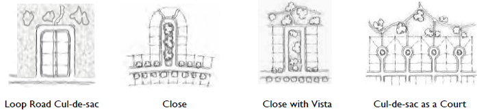
Cul-de-sacs should take one of the following forms listed in priority order from most desirable to least desirable (Table 2.2.50.A. Cul-de-Sac Diagrams):
(1)
"Loop Road" (internal lots front outward onto civic space).
(2)
"Close" or "Close with Vista" (lots front a centrally planted median).
(3)
A "Court" (lots fronting a centrally planted median).
B.
Reserved.
| Table 2.2.50.A: Cul-de-Sac Diagrams | |||
 |
2.2.60 - Pedestrian Circulation
A.
Pedestrian walkways shall comply with the standards found in Division 2.3 (Thoroughfare Standards) and be constructed concurrently with the thoroughfare or, if the thoroughfare is already constructed, prior to final inspection of any improvements. The Administrator may waive this requirement, using the process for Administrative Adjustment, as conveyed in Section 8.6.10 (Administrative Adjustment), if:
1.
An alternative, yet equally effective pedestrian way or pedestrian / bikeway currently exists, or will be provided outside the normal right-of-way; or
2.
Unique circumstances, topographic, or natural conditions prevail to the extent that strict adherence to said requirements would be unreasonable and not consistent with the Purposes of this Development Code or goals of the Comprehensive Plan.
B.
Reserved.
2.2.70 - Blocks
A.
Block Design. The design of blocks shall comply with the following:
1.
General.
a.
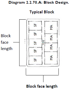
Where possible, blocks shall be laid out to have their short length abutting arterials, collectors, or the development's major road (see Diagram 2.2.70.A: Block Design).
b.
The length, width, and shape of blocks should be determined with regard to the provision of adequate sites for buildings of the type proposed, the standards of this Code, topography, fire access, emergency service, and police protection (see Diagram 2.2.70.A: Block Design).
2.
Block Shape and Size.
a.
Block Face and Perimeter. Individual block faces and the total block perimeter shall comply with the standards established in the Table 2.2.70.A (Block Size).
b.
Block Face and Perimeter Constraints. In cases where environmental or topographic constraints exist, or the property has an irregular shape, an Administrative Adjustment may be granted as set forth in Section 8.6.10 (Administrative Adjustments), and one of the following shall be provided:
(1)
An eight-foot, surfaced, pedestrian pathway easement (minimum surface width of five feet) shall be provided mid-block to connect parallel thoroughfares on the long side of the block; or,
(2)
An alley shall be provided mid-block to connect parallel thoroughfares on the long side of the block.
c.
Block Width. Blocks shall be, at a minimum, such width as will provide two tiers of lots.
3.
Reverse Frontage Lots. Reverse Frontage Lots shall be prohibited. Arterials and Collectors shall be incorporated into the structure of all future blocks, with access to the first tier of lots provided directly:
a.
From the thoroughfare, or
b.
From a Perpendicular Street, Rear Alley/Lane, or Parallel Access Road. Parallel Access Roads may only be used on Arterials in which the relevant area is not specifically addressed in the Beaufort County Thoroughfare Manual.
4.
Civic Space Set-Asides and Natural Resources. In areas where a grid or formal network is desired, exceptions would be made for green spaces along drainage or stream channels or where other natural resources make the grid difficult or cost prohibitive. The thoroughfare and block system should be designed to preserve and protect natural areas.
5.
Blocks with Industrial Development. Blocks intended for industrial development may vary from the elements of design contained in this Section if the nature of the use requires other treatment. In such cases, safe and convenient access to infrastructure, utilities, parking, and the thoroughfare system shall be provided. Deviations from the standards in this Section shall be approved by Administrative Adjustment as set forth in Section 8.6.10 (Administrative Adjustments).
B.
Reserved.
2.2.80 - Lots
A.
Lots shall be designed to ensure complete, double-tiered blocks, and comply with the following:
1.
Frontage. The primary frontage of a lot shall be along one of the following:
a.
Thoroughfare. A thoroughfare right-of-way;
b.
Single-loaded Frontage Streets. A thoroughfare with development on one side and a civic space on the other;
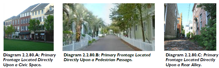
c.
Civic Space. Up to ten percent of the lots in a development may locate their primary frontage directly upon a civic space in which there is no thoroughfare located between the primary frontage and the civic space (see Diagram 2.2.80. A).
d.
Pedestrian Passage or Rear Alley/Lane. Up to five percent of the lots in a development may locate their primary frontage directly upon a Pedestrian Passage or Rear Alley / Lane (see Diagrams 2.2.80. B-C).
2.
Avoid Double Frontage Lots. New lots having double frontage, not located on a corner, shall not be permitted unless they are necessitated by size or topographic constraints. For existing lots with frontage on two streets, but not located on a corner, the minimum front setback shall be provided on each street.
3.
Access to Lots from Rear Alleys and Lanes.
a.
Alleys and Lanes that conform to the standards in Division 2.3 (Thoroughfare Standards) shall be provided along the rear property lines of lots intended for new residential, non-residential, and mixed-use development when the lots:
(1)
Are part of a block face with an average lot width of 55 feet or less at the building setback line (excluding lots on cul-de-sacs); or
(2)
Front an Arterial thoroughfare in which a Parallel Access Road is not present or planned (regardless of lot width).
b.
Lots served by alleys and lanes, including those in accordance with Subsection a. above, that are intended for new single-family, two-family, or multi-family dwellings shall:
(1)
Access garages and/or off-street parking areas from the alley as opposed to a primary thoroughfare.
(2)
Not have driveways in front or corner side yard areas.
4.
Driveway Access to Single and Two-Family Residential Lots. Driveways serving individual Single and Two-Family residential lots shall not have direct access onto Arterial thoroughfares, unless no alternative means of access exists (e.g., Perpendicular Road, Rear Alley, or Parallel Access Road), and it is unreasonable or impractical to require an alternative means of access.
5.
Consider Resources and Other Natural Features. The arrangement of lots shall reflect the location of protected resources and be sensitive to the other natural features of the property.
B.
Lot Width.
1.
Reflect General Conditions of Land. Lot width and frontage shall reflect the general conditions of the land on which the development is located, and provide a reasonable building envelope and adequate access to each lot.
2.
Where Grid System Exists. Where a grid street system exists, the lots should be as close to rectangular as feasible.
3.
When Resources Make Normal Lotting Difficult. Where natural resources or property shape make normal lotting difficult, common drives or shared easements may be considered.
a.
Flag Lots. Flag Lots are prohibited and may only be permitted using the process for Administrative Adjustment, as conveyed in Section 8.6.10 (Administrative Adjustment), if:
(1)
Connectivity and circulation via a network of streets, alleys, pathways, etc., will be maintained;
(2)
There is no reasonable alternative due to extreme topographic conditions or other physical conditions; and
(3)
The lot has an access strip with a minimum width of 20 feet serving the main building site of the property. The front setback on flag lots shall be measured from the front property line within the main building site as opposed to the property line adjoining the public right-of-way.
b.
Reserved.
C.
Lot Lines. Lot lines shall comply with the following:
1.
General. Generally, side lot lines shall be perpendicular or radial to the thoroughfare, and rear lines should be approximately parallel to thoroughfare lines. However, different lot shapes are allowed if it is demonstrated they are necessary or desirable to:
a.
Better relate building sites to the terrain on the site, or to provide better site utilization and building relationships;
b.
Preserve protected resources or other natural features while still providing generally rectangular building envelopes;
c.
Better integrate civic space set-asides while still providing generally rectangular building envelopes; or
d.
Create a more efficient lot design and layout while still providing generally rectangular building envelopes.
2.
Depth of Lots. The depth of residential lots shall not be less than their width.
D.
Minimum Lot Elevation and Drainage.
1.
General. Lots shall be provided with adequate drainage in accordance with this Code and all other relevant requirements, and shall be graded, so as to drain surface water away from the building(s).
2.
Prevent Ponding or Flooding. The minimum elevation of the lot shall be a level that will prevent ponding or flooding as a result of heavy rain, or during abnormally high tides.
3.
Drain Lot. The entire lot shall be properly drained at a minimum slope of one-eighth inch per foot toward roadside and/or lot swales.
2.2.90 - Access Management
A.
Access to Town, State, and Federal Thoroughfares. Access to Town, State, and Federal thoroughfares shall comply with the standards established in this Section; and shall compliment the standards established in: the Beaufort County Technical Manual, Division 2.3 (Thoroughfare Standards), Article 3 (Specific to Zones), and this Development Code.
1.
Curb Cuts and Access Points. Ingress-egress openings commonly referred to as "curb cuts" shall be regulated by zoning district.
2.
Combine Curb Cuts and Access Points. To the maximum extent practicable, curb cuts and other vehicular access points along a street shall be combined.
3.
Size of Curb Cuts and Access Points. In no case shall a curb cut or other vehicular access point be less than nine feet or more than 25 feet in width.
4.
Location of Curb Cuts and Access Points. At street intersections, no "curb cut" shall be located closer than: 20 feet from the intersecting point of the two street right-of-way property lines involved (or such lines extended in case of a rounded corner); or 25 feet from the intersection of the two curb lines involved (or such lines extended in case of a rounded corner), whichever is the least restrictive.
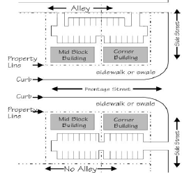
Diagram 2.2.90.A: Access through parking lots.
B.
Access Through Parking Lots. Linkages between parking areas within the perimeter of the block (and half block) should be encouraged when a rear alley or lane is present, and shall be provided when there is no rear alley or lane. See Diagram 2.2.90.A (Access through parking lots).
C.
Gated Communities. Communities that limit access by the public through the utilization of entryway gates interfere with interconnectivity and vehicular and pedestrian mobility and shall be prohibited.
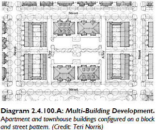
2.2.100 - Multi-Building Development
A.
Applicability. The following standards apply to all multi-building developments of a residential, mixed use, commercial, civic, and light industrial orientation, except:
1.
Single-Family and Two-Family Residential development.
2.
Personal Storage Facilities. Design Standards specific to Personal Storage Facilities are located in Division 4.2 (Conditional Use Regulations).
B.
Site Planning. To the maximum extent practicable sites with multiple buildings shall:
1.
Maintain or establish an uninterrupted and interconnected network of blocks and streets as conveyed in Division 2.2.70 (Blocks) and Sub-section 2.2.40.A.2 (Thoroughfare Design);
2.
Design all public or private vehicular rights-of-way, easements, access-ways, and driveways that are internal to a site to the standards of Division 2.3 (Thoroughfare Standards);
3.
Configure and locate buildings to define street edges, development entry points, and spaces for gathering between buildings;
4.
Frame and enclose parking areas, public spaces, and site amenities on at least three sides;
5.
Locate public gathering spaces at prominent corners; and
6.
Provide terminating vistas in order to "break-up" a thoroughfare or define its end.
C.
Building Orientation.
1.
The building facade containing the primary entrance shall be considered as the principal facade.
2.
To the maximum extent practicable:
a.
Perimeter and interior buildings shall be oriented so that the principal facade faces a public street or public space (street or space may be privately owned); and
b.
Perimeter or outparcel buildings shall "wrap" the overall site, establishing a combined frontage buildout along the perimeter street as conveyed in Article 3 (Specific to Zones).
D.
Parking.
1.
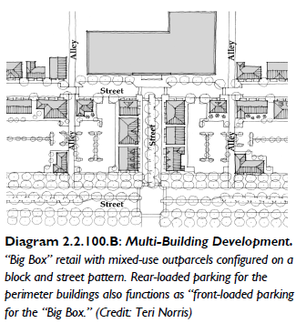
There shall be no parking between a building and the street it fronts, except:
a.
On-street parallel or angled parking; or
b.
Conventional "front-loaded" parking lots permitted for buildings of 35,000 sf. or more. See Section 5.2.50 (Large Footprint Building) and Diagram 2.2.100.B (Multi-Building Development).
2.
Type and design of on-street parking shall comply with Division 2.3 (Thoroughfare Standards).
3.
"Head-in "or "front-in" parking shall only be permitted as set forth in Article 3 (Specific to Zones) and Division 5.6 (Off-Street Parking).
E.
Street Trees.
1.
All internal streets shall contain street trees as established in Tables 2.3.70.A (Street Landscaping), 2.3.90.G (Public Planting), and 2.3.90.H (Clear Height Under Trees).
2.
Reserved.
F.
Pedestrian Walkways. Pedestrian walkways internal to a site shall:
1.
Connect all buildings within a multi-building development with the larger pedestrian network surrounding the site;
2.
Have a minimum width as conveyed in Table 2.3.90.A (Thoroughfare Formulas);
3.
Be provided along the full length of building facades with an entryway or facing off-street parking areas; and
4.
Provide crosswalks at all intersections and other street crossings (both external and internal to the site) where a high-level of pedestrian movement is anticipated to maximize pedestrian safety.
2.2.110 - Civic Space Set-Asides
A.
Civic space set-asides shall comply with Division 2.4 (Civic Space Types).
B.
The amount of civic space set-asides is set forth in Section 2.4.50 (Set Aside Requirement).
2.3.10 - Purpose
The intent of this Division is to provide a catalog of pre-approved thoroughfare components and assemblies that are appropriate to use within each transect zone. Components can be combined to form thoroughfares. Assemblies are pre-approved groupings of components. Both are suitable for use in new developments, as well as the retrofit of existing locations, and can be used in subdivision and community planning activities that promote walkable places.
2.3.20 - Applicability
A.
This Division describes the standards for developing thoroughfares within transect zones. It supplements the "Beaufort County Technical Manual." Where these standards conflict with the "Beaufort County Technical Manual", the standards of this division shall prevail.
B.
These standards are applicable for the transformation of existing thoroughfares and the creation of new thoroughfares in any area within a transect zone.
C.
Thoroughfare standards are applicable for the design of collector and local streets. Thoroughfare standards applied to existing arterials and roadways under the jurisdiction of the South Carolina Department of Transportation may require additional review in order to obtain approval.
D.
Additional thoroughfare assemblies can be integrated into this division as they are approved by the Town.
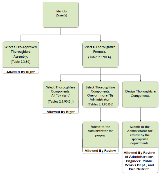
2.3.30 - Assembling/Designing a Thoroughfare
There are three general procedures for assembling or designing a thoroughfare for approval.
A.
Choose a predefined thoroughfare assembly found in Section 2.3.80 (Thoroughfare Assemblies). These thoroughfare assemblies are allowed by right;
B.
Assemble a thoroughfare that matches the standards found in Table 2.3.90.A (Thoroughfare Formulas) and use only the predefined components in Tables 2.3.90.B—J.
a.
If all of the predefined components are permitted:
then the thoroughfare is permitted without additional review.
b.
If one or more of the predefined components is permitted:
then the thoroughfare shall be submitted for additional review by the Administrator.
C.
Design a thoroughfare that matches the standards found in Table 2.3.90A (Thoroughfare Formulas) but utilizes components that differ from the predefined components in Tables 2.3.90.B—J. This thoroughfare will require approval by the Town, including the Zoning Administrator, Engineer, Public Works Division, and Fire District representatives.
2.3.40 - Thoroughfare Design
A.
Thoroughfares are intended for use by vehicular and pedestrian traffic and to provide access to lots and civic spaces.
B.
Thoroughfares shall generally consist of vehicular lanes and public frontages.
C.
Thoroughfares shall be designed in context with the urban form and general intention of the zones through which they pass.
1.
Within the more urban transect zones (T3 through T5) pedestrian comfort shall be a primary consideration of the thoroughfare design. Design conflict between vehicular and pedestrian movement generally shall be decided in favor of the pedestrian.
2.
Within the most rural transect zones (T1) pedestrian comfort shall be a secondary consideration of the thoroughfare design. Design conflict between vehicular and pedestrian movement generally shall be decided in favor of the vehicle.
D.
The requirements for pedestrian and bicyclist safety, comfort and access shall establish thoroughfare movement type and design speed. The movement type and design speed then determine the dimensions of each thoroughfare element, such as vehicular lanes and turning (curb) radii.
E.
Thoroughfares shall be designed according to the types of vehicles expected to use each thoroughfare on a daily basis. Occasionally, large vehicles are expected on all thoroughfares. All thoroughfares shall allow these vehicles to safely pass without major difficulty. It is expected that large vehicles may cross the centerline when making turning movements.
F.
Other factors that may need to be considered in the selection of an appropriate thoroughfare type in transect zones include the following:
1.
Parking. Parking availability on-site or on the thoroughfare will influence the appropriate thoroughfare type. Parking will also be determined by lot size and use.
2.
Truck Access. Thoroughfares that provide access to high volumes of large trucks may need additional design considerations to mitigate potential negative effects on walkability.
3.
Bus Service. Thoroughfares that will serve as a public transit or school bus routes may need additional design considerations, including, but not limited to, the location of bus stops.
4.
Stormwater. Thoroughfares may be designed to accommodate stormwater treatment and retention facilities.
G.
All lane dimensions shall be measured to the face of the curb. Where no curb and gutter is provided, the lane dimension shall be to the edge of the pavement.
H.
Traffic Control and Street Signs. Traffic control and street signs, constructed to required specifications, shall be installed at all thoroughfare intersections at the developer's expense.
2.3.50 - Movement Types and Design Speed
Movement types are intended to assist in the selection of the appropriate thoroughfare design for the necessary level of pedestrian and bicyclist safety and comfort at any given location. Design speed is the primary determinant of movement type. A list of approved movement types (along with their assigned lane widths and curb radii) is provided for each transect zone in Tables 2.3.90.A-D.
Following is a list of movement types:
A.
Yield. Drivers must proceed slowly, with extreme care, and must yield to approaching traffic when vehicles are parked on both sides of the thoroughfare creating essentially one through lane. A Yield thoroughfare is the functional equivalent of traffic calming. In addition to yield movement use on normal thoroughfares, this movement is used for alleys and rear lanes. For these applications, the primary purpose is access to rear loaded driveways/access for residential and commercial property. Design speed is less than 20 mph.
B.
Slow. Drivers can proceed carefully with an occasional stop to allow a pedestrian to cross or another car to park. The character of the thoroughfare should make drivers uncomfortable exceeding the design speed due to the presence of parked cars, sense of enclosure from buildings and street trees, tight turning radii, and other design elements. Design speed is 20—25 mph.
C.
Low. Drivers can generally expect to travel without delay at the appropriate design speed. Thoroughfare design supports safe pedestrian movement at the higher design speed. This movement type is appropriate for thoroughfares designed to traverse longer distances or connect to higher intensity locations. Design speed is 30—35 mph.
D.
Suburban. This is a conventional thoroughfare design in which drivers can expect a separation of modes (i.e., bike lanes, walking paths and roads) allowing automobiles to travel unimpeded by pedestrians or walkability concerns. This movement type is rarely used in the T3 through T5 Transect Zones, but may be needed when a thoroughfare crosses through the T1 Transect Zone. Design speed may be above 35 mph.
The design criteria for Yield, Slow, and Low thoroughfares shall be commensurate with local thoroughfares. Design speeds higher than 35 mph shall not be used in areas intended to support moderate or high levels of pedestrian or bicycle activity due to concerns with safety and comfort.
2.3.60 - Intersections
A.
Turning Movements.
1.
Street design of narrow streets and compact intersections requires designers to pay close attention to the operational needs of transit, fire and rescue, waste collection and delivery trucks. For this reason, early coordination with transit, fire and rescue, waste collection and other stakeholder groups is essential.
2.
More regular encroachment of turning vehicles into opposing lanes will occur at compact intersections. Therefore, frequency of access, traffic volumes and the speeds on intersecting streets at those intersections must be considered when designing intersections. For fire and rescue, determination of the importance of that street for community access should be determined, e.g., primary or secondary access.
3.
When present, bike lanes and on-street parking will increase the effective curb return radius, when curb extensions are not employed, by providing more room for the wheel tracking of turning vehicles. The designer should use turning templates or software to evaluate intersections to ensure adequate operation of vehicles can occur. Location of on-street parking around intersections should be evaluated during this analysis to identify potential conflicts between turning vehicles and on-street parking.
B.
Visual Obstructions. No fence, wall, tree, terrace, building, sign, shrubbery, hedge, or other planting or structure or object capable of obstructing driver vision shall be allowed at intersections.
C.
Street Jogs. Street intersection jogs or centerline offsets of less than 150 feet are prohibited in the horizontal alignment of streets across intersections.
D.
Intersections. The centerline of no more than two streets should intersect at any one point. Streets should be laid out so as to intersect as nearly as possible at right angles. No street should intersect another street at less than 60 degrees.
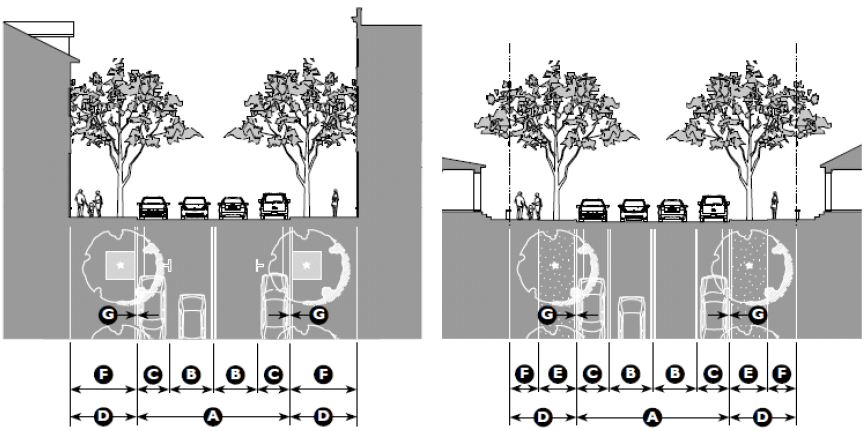
2.3.70 - Public Frontages
A.
The public frontage contributes to the character of the zone, and includes the types of sidewalk, curb, planter, and street trees.
B.
Public frontages shall be designed and allocated within zones as shown in Table 2.3.90.E (Public Frontage Types) and Table 2.3.90.F (Public Frontage Standards).
C.
Within the public frontages, the prescribed types of public planting and public lighting shall be as shown in Tables 2.3.90.G—J. The spacing may be adjusted with the approval of the Administrator to accommodate specific site conditions.
D.
Existing trees may count towards the street tree requirement if approved by the Administrator.
1.
Proposed street tree height and type shall be appropriate for the frontage conditions. Trees with existing or potential canopy covering thoroughfares, civic spaces or parking spaces shall be of a type that, at maturity or with minor pruning at installation, provide a clear height as describe in the Table 2.3.90.H (Clear Height Under Trees).
2.
Reserved.
E.
Street Landscaping. Refer to Table 2.3.70.A (Street Landscaping) for standards.
F.
Public Utilities. Public utilities (water, sewer, electric, gas, cable) shall be buried, as conveyed in Sub-section 2.5.40.B (Utility Easements and Lines). Utilities shall be planned and constructed to use the right of way or easement associated with rear lanes or alleys first (the default), and thoroughfares second.
2.3.80 - Thoroughfare Assemblies
A.
This Section provides thoroughfare assemblies that have been pre-approved by the Town for use in transect zones.
B.
The thoroughfares assemblies in table 2.3.80 (Thoroughfare Assemblies) shall be approved "By-Right" when designed as conveyed.
| Table 2.3.80 Thoroughfare Assemblies | ||||||
 | ||||||
| Thoroughfare Assembly CS-58-34 | ||||||
| Application | Public-Frontage Assembly | |||||
| Transect Zones | Public Frontage Type | Commercial Street | ||||
| Drainage Collection Type | Curb and Gutter | |||||
| Movement Type | Slow | Planter Type | 4' x 4' Tree Well | |||
| Design Speed | 20 mph | Landscape Type | Trees at 30' o.c. avg. | |||
| Overall Widths | Lighting Type |
Post, Column, or Double
Column | ||||
| Right-of-Way (ROW) Width | 58' | |||||
| Pavement Width | 34' | Walkway Type | 12' Sidewalk | |||
| Lane Assembly | Curb Type | Square | ||||
| Traffic Lanes | 2 @ 10' | Intersection | ||||
| Bicycle Lanes | None | Curb Radius | 10' max | |||
| Parking Lanes | 2 @ 7' marked | |||||
| Medians | None | |||||
| Table 2.3.80 Thoroughfare Assemblies | ||||||
 | ||||||
| Thoroughfare Assembly CS-80-54 | ||||||
| Application | Public-Frontage Assembly | |||||
| Transect Zones | Public Frontage Type | Commercial Street | ||||
| Drainage Collection Type | Curb and Gutter | |||||
| Movement Type | Slow | Planter Type | 5' x 5' Tree Well | |||
| Design Speed | 20 mph | Landscape Type | Trees at 30' o.c. avg. | |||
| Overall Widths | Lighting Type | Post or Column | ||||
| Right-of-Way (ROW) Width | 80' | Walkway Type | 13' Sidewalk | |||
| Pavement Width | 54' | Curb Type | Square | |||
| Lane Assembly | Intersection | |||||
| Traffic Lanes | 2 @ 10' | Curb Radius | 10' max | |||
| Bicycle Lanes | >None | |||||
| Parking Lanes | 2 @ 17' marked | |||||
| Medians | None | |||||
| Table 2.3.80 Thoroughfare Assemblies | ||||||
 | ||||||
| Thoroughfare Assembly ST-56-36 | ||||||
| Application | Public-Frontage Assembly | |||||
| Transect Zones | Public Frontage Type | Street | ||||
| Drainage Collection Type | Curb and Gutter | |||||
| Movement Type | Slow | Planter Type | 5' Continuous Planter | |||
| Design Speed | 20 mph | Landscape Type | Trees at 30' o.c. avg. | |||
| Overall Widths | Lighting Type | Post or Column | ||||
| Right-of-Way (ROW) Width | 56' | Walkway Type | 5' Sidewalk | |||
| Pavement Width | 36' | Curb Type | Square | |||
| Lane Assembly | Intersection | |||||
| Traffic Lanes | 2 @ 11' | Curb Radius | 10' max | |||
| Bicycle Lanes | None | |||||
| Parking Lanes | 2 @ 7' marked | |||||
| Medians | None | |||||
| Table 2.3.80 Thoroughfare Assemblies | ||||||
 | ||||||
| Thoroughfare Assembly RD-50-18 | ||||||
| Application | Public-Frontage Assembly | |||||
| Transect Zones | Public Frontage Type | Road | ||||
| Drainage Collection Type | 2' Gutter Pan | |||||
| Movement Type | Slow | Planter Type | 9' Continuous Planter | |||
| Design Speed | 20 mph | Landscape Type | Trees at 30' o.c. avg. | |||
| Overall Widths | Lighting Type | Pipe, Post or Column | ||||
| Right-of-Way (ROW) Width | 50' | Walkway Type | 5' Sidewalk | |||
| Pavement Width | 18' | Curb Type | Rolled Curb | |||
| Lane Assembly | Intersection | |||||
| Traffic Lanes | 2 @ 9' | Curb Radius | 10' max | |||
| Bicycle Lanes | None | |||||
| Parking Lanes | 2 @ 9' stabilized soil | |||||
| Medians | None | |||||
| Table 2.3.80 Thoroughfare Assemblies | ||||||
 | ||||||
| Thoroughfare Assembly RD-50-26 | ||||||
| Application | Public-Frontage Assembly | |||||
| Transect Zones | Public Frontage Type | Road | ||||
| Drainage Collection Type | 2' Gutter Pan | |||||
| Movement Type | Slow | Planter Type | 5' Continuous Planter | |||
| Design Speed | 20 mph | Landscape Type | Trees at 30' o.c. avg. | |||
| Overall Widths | Lighting Type | Pipe or Post | ||||
| Right-of-Way (ROW) Width | 50' | Walkway Type | 5' Sidewalk | |||
| Pavement Width | 26' | Curb Type | Rolled Curb | |||
| Lane Assembly | Intersection | |||||
| Traffic Lanes | 2 @ 9' | Curb Radius | 10' max | |||
| Bicycle Lanes | None | |||||
| Parking Lanes | 1 @ 8' marked | |||||
| Medians | None | |||||
| Table 2.3.80 Thoroughfare Assemblies | ||||||
 | ||||||
| Thoroughfare Assembly RL-20-12 | ||||||
| Application | Public-Frontage Assembly | |||||
| Transect Zones | Public Frontage Type | Rear Lane | ||||
| Drainage Collection Type | Gutter Pan and/or Swale, may be reinforced for fire safety. | |||||
| Movement Type | Yield | |||||
| Design Speed | <20 mph | Planter Type | None | |||
| Overall Widths | Landscape Type | None | ||||
| Right-of-Way (ROW) Width | 20' | Lighting Type | Pipe or Post | |||
| Pavement Width | 12' | Walkway Type | None | |||
| Lane Assembly | Curb Type | Rolled or Flush | ||||
| Traffic Lanes | 1 @ 12' | Intersection | ||||
| Bicycle Lanes | None | Curb Radius | 10' max | |||
| Parking Lanes | None | |||||
| Medians | None | |||||
| Table 2.3.80 Thoroughfare Assemblies | ||||||
 | ||||||
| Thoroughfare Assembly RA-24-21 | ||||||
| Application | Public-Frontage Assembly | |||||
| Transect Zones | Public Frontage Type | Rear Alley | ||||
| Drainage Collection Type | Gutter Pan | |||||
| Movement Type | Yield | Planter Type | None | |||
| Design Speed | <20 mph | Landscape Type | None | |||
| Overall Widths | Lighting Type | Pipe or Post | ||||
| Right-of-Way (ROW) Width | 24' | Walkway Type | None | |||
| Pavement Width | 21' | Curb Type | Rolled or Flush | |||
| Lane Assembly | Intersection | |||||
| Traffic Lanes | 2 @ 10'6" | Curb Radius | 10' max | |||
| Bicycle Lanes | None | |||||
| Parking Lanes | None | |||||
| Medians | None | |||||
2.3.90 - Thoroughfare Formulas and Components
A.
This Section provides the components of thoroughfares that have been approved by the Town for use in transect zones.
B.
The formulas and components that follow may be used as conveyed in Section 2.3.30 (Assembling / Designing a Thoroughfare) to design a complete thoroughfare assembly for approval in the transect zones.
| Table 2.3.90.A: Thoroughfare Formulas | |||||||
|---|---|---|---|---|---|---|---|
|
Allowed
Movement Types | Speed |
Lane Assembly
|
Public Frontage Assembly
| ||||
|
TravelLanes
|
Parking
|
Planter
|
Path
|
Assembly
|
Edge
| ||
| Slow 20 | 20 mph | 9' | - | 5' min. | 8' min. | 14' min. | R or C |
| Slow 25 | 25 mph | 10' | - | 5' min. | 8' min. | 14' min. | R or C |
| Low 30 | 30 mph | 10' | - | 5' min. | 8' min. | 14' min. | R or C |
| Low 35 | 35 mph | 11' | - | 5' min. | 8' min. | 14' min. | R or C |
| Yield: Rear Lane | 10 mph | 12' | 4' min. | 4' min. | R, C, or RB | ||
| Yield 1 | <20 mph | 12' | 7' | 5' min. | 5' min. | 10' min. | R or C |
| Slow 20 | 20 mph | 9' | 7' | 5' min. | 5' min. | 10' min. | R or C |
| Slow 25 | 25 mph | 10' | 7' | 5' min. | 5' min. | 10' min. | R or C |
| Low 30 | 30 mph | 10' | 8' | 5' min. | 5' min. | 10' min. | R or C |
| Allowed Movement Types | Speed | LaneAssembly | Public Frontage Assembly | ||||
| TravelLanes | Parking | Planter | Path | Assembly | Edge | ||
| Yield: Alley | 10 mph | 21' | min. | 1.5' min. | RB | ||
| Yield 1 | <20 mph | 12' | 7' | 5' min. | 6' min. | 12' min. | C |
| Slow 20 | 20 mph | 9' | 7' | 5' min. | 6' min. | 12' min. | C |
| Slow 20 w/ 45° parking | 20 mph | 12' | 16' 2 | 5' min. | 6' min. | 12' min. | C |
| Slow 25 | 25 mph | 10' | 7' | 5' min. | 6' min. | 12' min. | C |
| Slow 20 w/ 45° parking | 25 mph | 10'/12' | 18' 2 | 5' min. | 6' min. | 12' min. | C |
| Low 30 | 30 mph | 10' | 8' | 5' min. | 6' min. | 12' min. | C |
| Allowed Movement Types | Speed | LaneAssembly | Public Frontage Assembly | ||||
| TravelLanes | Parking | Planter | Path | Assembly | Edge | ||
| Yield: Alley | 10 mph | 21' | min. | 1.5' min. | RB | ||
| Slow 20 | 20 mph | 9' | 7' | 5' min. | 6' min. | 12' min. | C |
| Slow 20 w/ 45° parking | 20 mph | 12' | 16' 2 | 5' min. | 6' min. | 12' min. | C |
| Slow 25 | 25 mph | 10' | 7' | 5' min. | 6' min. | 12' min. | C |
| Slow 25 w/ 45° parking | 25 mph | 12' | 18' 2 | 5' min. | 6' min. | 12' min. | C |
| Low 30 | 30 mph | 10' | 8' | 5' min. | 6' min. | 12' min. | C |
| Low 35 | 35 mph | 11' | 8' | 5' min. | 7' min. | 12' min. | C |
| Notes: | |||||||
| 1 If provided. | |||||||
| 1 Parking is required on at least one side in order to facilitate yield movement. | |||||||
| 2 16' min. for reverse angled parking; 18; min. for head-in angled parking. | |||||||
| Key | |||||||
| R = Rural Edge Treatment | C = Curb Edge Treatment | RB = Ribbon Curb (18") | |||||
|
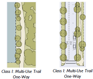
Table 2.3.90.B: Bicycle Facilities Standards
Class I: Multi-Use Trail | ||||
 | ||||
| Transect Zones | ||||
| Width | ||||
| One-way | 8 feet | |||
| Two-way | 12 feet | |||
Class II: Bicycle Lane | ||||
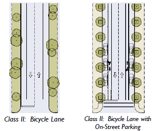 | ||||
| Transect Zones | ||||
| Width Adjacent to: | ||||
| Rural Edge | 5 feet minimum | |||
| Parking | 6 feet minimum | |||
| Curb and Gutter | 5 ½ feet to face of curb | |||
|
Design Speed of
Thoroughfare | >25 mph | |||
Class III: Shared Lanes/Bicycle Boulevard | ||||
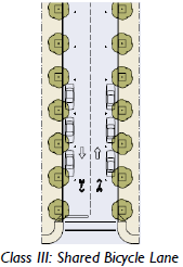 | ||||
| Transect Zones | ||||
Width Design Speed of Thoroughfare | No minimum 25 mph or less | |||
| Table 2.3.90.C: Curb Radius | |||||
| This table provides the radius for curbs at the intersection of thoroughfares. | |||||
| Movement Type | Speed | Curb Radius 1 | |||
| Yield | <20 mph | 5'—10' | |||
| Slow | 20—25 mph | 10'—15' | |||
| Low | 30—35 mph | 15'—20' | |||
| Notes: | |||||
| 1 With on-street parking, or bike lanes and no curb extensions or bulb-outs. | |||||
| Curb Radius with Suburban Movement Type may be 25' max. | |||||
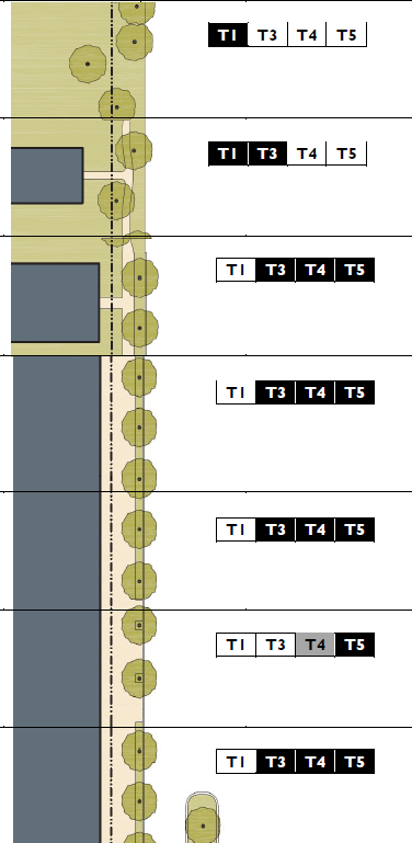
| Table 2.3.90.D: Vehicular Lane Assemblies | |||
| Movement Type | Yield | Slow | Slow |
| Design Speed | <20 MPH | 20 MPH | 25 MPH |
| No Parking | 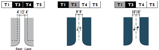 | ||
| No Parking | 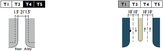 | ||
| Limited Parking | 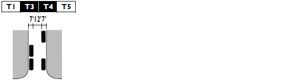 | ||
| Table 2.3.90.D: Vehicular Lane Assemblies (continued) | |||
| Movement Type | Low | Low | |
| Design Speed | 30 MPH | 35 MPH | |
|
No Parking
(continued) | 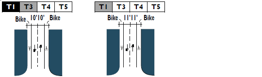 | ||
|
No Parking
(continued) | 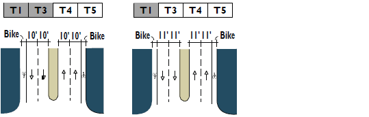 | ||
|
Limited Parking
(continued) | |||
| Table 2.3.90.D: Vehicular Lane Assemblies (continued) | |||
| Movement Type | Yield | Slow | Slow |
| Design Speed | <20 MPH | 20 MPH | 25 MPH |
|
One-Side Parking
(continued) | 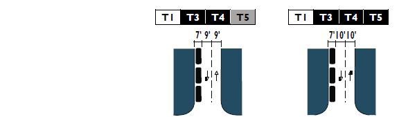 | ||
|
Two-Side Parking
(continued) | 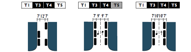 | ||
| Angle Parking | 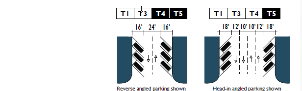 | ||
| Table 2.3.90.D: Vehicular Lane Assemblies (continued) | |||
| Movement Type | Low | Low | |
| Design Speed | 30 MPH | 35 MPH | |
|
One-Side Parking
(continued) | 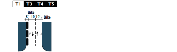 | ||
|
Two-Side Parking
(continued) | 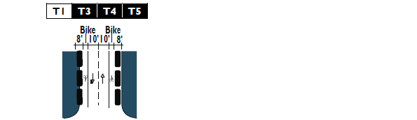 | ||
|
Angle Parking
(continued) | |||
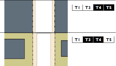
| Table 2.3.90.D: Vehicular Lane Assemblies (continued) | |||
| Movement Type | Yield | Slow | Slow |
| Design Speed | <20 MPH | 20 MPH | 25 MPH |
| Medians With Parking | 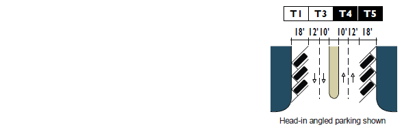 | ||
| Medians With Parking | |||
| Medians With Parking | |||
| Table 2.3.90.D: Vehicular Lane Assemblies (continued) | |||
| Movement Type | Low | Low | |
| Design Speed | 30 MPH | 35 MPH | |
|
Medians With Parking
(continued) |  | ||
|
Medians With Parking
(continued) | 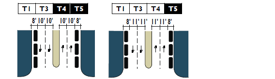 | ||
|
Medians With Parking
(continued) |  | ||
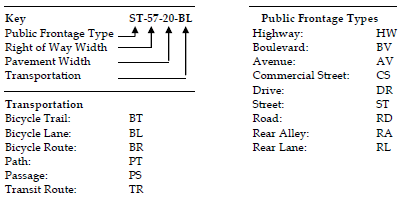
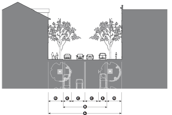
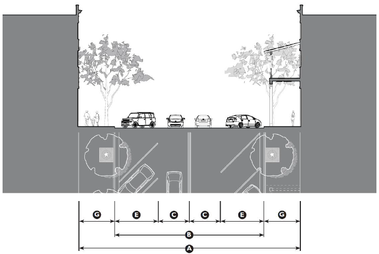
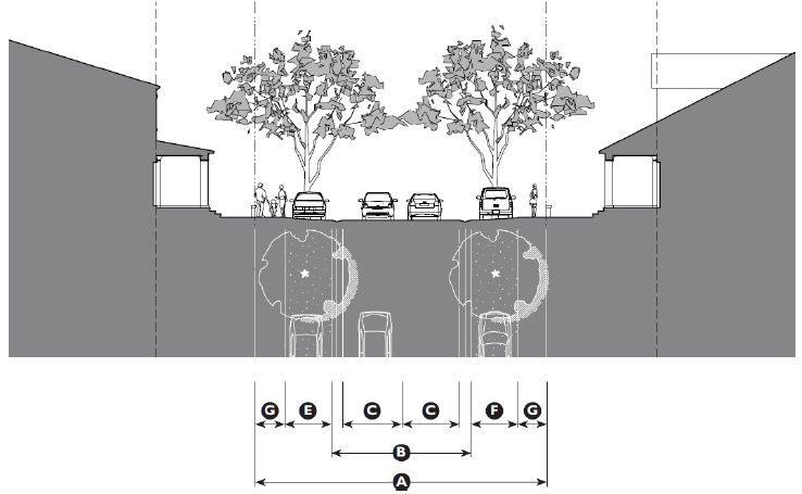
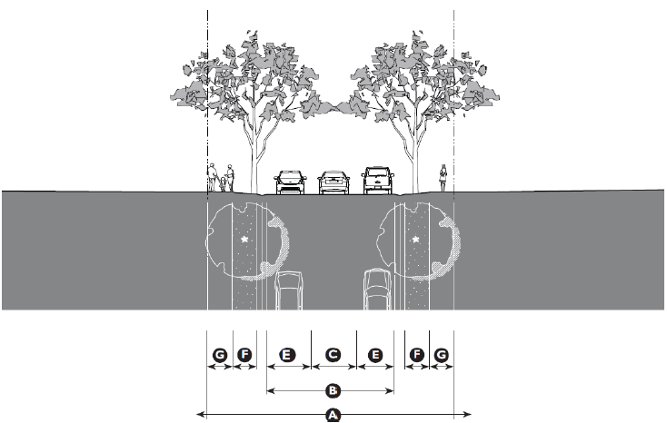
| Table 2.3.90.E: Public Frontage Types | ||||
| The public frontage is the area between the curb of the vehicular lanes and the Property Line/ROW. Dimensions are provided in Table 2.3.80F (Public Frontage Standards). | ||||
| Public Frontage Type |
LOT
PRIVATE FRONTAGE |
R.O.W.
PUBLIC FRONTAGE | Zone | |
| (HW) For Highway: The For Highway Frontage has bicycle trails, no parking and open swales drained
by percolation. The landscaping consists of the natural condition or multiple species
arrayed in naturalistic clusters. Buildings are buffered by land and distance.
|  | |||
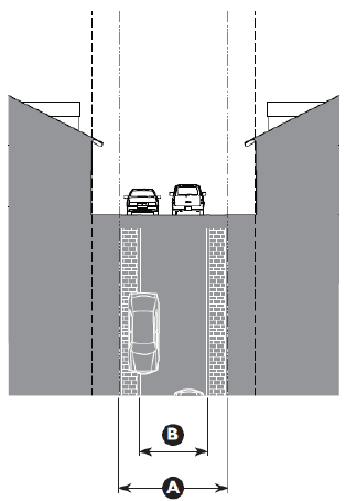
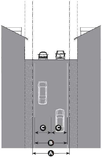
| (RD) For Road: The For Road Frontage has open swales drained by percolation, a walking path or
bicycle trail along one or both sides, and yield parking. The landscaping consists
of multiple species arrayed in naturalistic clusters.
| ||||
| (ST) For Street: The For Street Frontage has raised curbs drained by inlets and sidewalks separated
from the vehicular lanes by individual or continuous planters. The landscaping consists
of street trees of a single or alternating species aligned in a regularly spaced allee.
1
| ||||
| (DR) For Drive: The For Drive Frontage has raised curbs drained by inlets and a wide sidewalk or
paved path along one side, related to a civic space. It is separated from the vehicular
lanes by individual or continuous planters. The landscaping consists of street trees
of a single or alternating species aligned in a regularly spaced allee.
| ||||
| (AV) For Avenue: The Avenue Frontage has raised curbs drained by inlets and wide sidewalks separated
from the vehicular lanes by a narrow continuous planter with parking on both sides.
The landscaping consists of a single tree species aligned in a regularly spaced allee.
| ||||
| (CS) For Commercial Street or Avenue: The For Commercial Street or Avenue Frontage has raised curbs drained by inlets
and very wide sidewalks along both sides separated from the vehicular lanes by separate
tree wells with grates. The landscaping consists of a single tree species aligned
with regular spacing where possible.
| ||||
| (BV) For Boulevard: The Boulevard Frontage has slip roads on both sides. It consists of raised curbs drained by inlets and sidewalks along both sides, separated from the vehicular lanes by planters. The landscaping consists of double rows of a single tree species aligned in a regularly spaced allee. | ||||
| Notes: | ||||
| 1 Streets with a ROW width of 40 feet or less are exempt from tree standards. | ||||
| Table 2.3.90.E: Public Frontage Types(continued) | ||||
| The public frontage is the area between the curb of the vehicular lanes and the Property Line/ROW. Dimensions are provided in Table 2.3.80F (Public Frontage Standards). | ||||
| Public Frontage Type |
LOT
PRIVATE FRONTAGE |
R.O.W.
PUBLIC FRONTAGE | Zone | |
| (RA) For Real Alley: The Rear Alley Frontage is located to the rear of lots. It consists of a paved surface
and ribbon curb at the edges adjacent to property lines or buildings. Alleys are typically
not landscaped.
|  | |||
| (RL) For Real Lane: The Real Lane Frontage is located to the rear of lots. It consists of a paved surface
and compacted gravel or similar material placed on the outer edges. Lanes are typically
not landscaped.
| ||||
| Notes: | ||||
| 1 Streets with a ROW width of 40 feet or less are exempt from tree standards. | ||||
| Table 2.3.90.F: Public Frontage Standards | |||
| This table assembles prescriptions and dimensions for the public frontage elements - curbs, walkways, and planters - relative to specific thoroughfare types within transect zones. The Assembly row assembles all of the elements for the various thoroughfare types. | |||
| Transect Zone | |||
| Public Frontage Type | HW-RD-ST | RD & ST | ST-DR-AV |
| Assembly: The principal variables are the type and dimension of curbs, walkways, planters and landscape. | 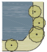 | 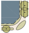 | 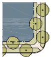 |
| Total Width | 14'—22' | 14'—22' | 10'—17' |
| Curb: The detailing of the edge of the vehicular pavement, incorporating drainage. |  |  |  |
| Type | Rural (Open Swale) | Rolled Curb (Valley Gutter) | Raised Curb |
| Radius | 5'—20' | 5'—20' | 5'—20' |
| Path/Walkway: The pavement dedicated exclusively to pedestrian activity. |  |  |  |
| Type | Path | Sidewalk | Sidewalk |
| Width | 8' One-way; 12' Two-way | 5' min. | 5' min. |
| Table 2.3.90.F: Public Frontage Standards (continued) | |||
| This table assembles prescriptions and dimensions for the public frontage elements - curbs, walkways, and planters - relative to specific thoroughfare types within transect zones. The Assembly row assembles all of the elements for the various thoroughfare types. | |||
| Transect Zone | |||
| Public Frontage Type | HW-RD-ST | RD & ST | ST-DR-AV |
| Planter: The layer which accommodates street trees and other landscape. | 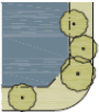 |  | 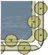 |
| Arrangement | Clustered | Clustered | Regular |
| Species | Multiple | Multiple | Multiple |
| Type | Continuous Planter | Continuous Planter | Continuous Planter |
| Width | 5' min. | 5' min. | 5' min. |
| Table 2.3.90.F: Public Frontage Standards (continued) | |||
| This table assembles prescriptions and dimensions for the public frontage elements - curbs, walkways, and planters - relative to specific thoroughfare types within transect zones. The Assembly row assembles all of the elements for the various thoroughfare types. | |||
| Transect Zone | |||
| Public Frontage Type | ST-DR-AV-BV | CS-DR-AV-BV | CS-DR-AV-BV |
| Assembly: The principal variables are the type and dimension of curbs, walkways, planters and landscape. | 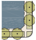 | 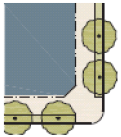 | 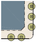 |
| Total Width | 12'—16' | 12'—22' | 12'—24' |
| Curb: The detailing of the edge of the vehicular pavement, incorporating drainage. |  |  |  |
| Type | Raised | Rolled Curb (Valley Gutter) | Raised Curb |
| Radius | 5'—20' | 5'—20' | 5'—20' |
| Path/Walkway: The pavement dedicated exclusively to pedestrian activity. | 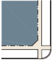 |  | 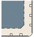 |
| Type | Sidewalk | Sidewalk | Sidewalk |
| Width | 5' min.. 7' max. | 5' min. | 5' min. |
| Table 2.3.90.F: Public Frontage Standards (continued) | |||
| This table assembles prescriptions and dimensions for the public frontage elements - curbs, walkways, and planters - relative to specific thoroughfare types within transect zones. The Assembly row assembles all of the elements for the various thoroughfare types. | |||
| Transect Zone | |||
| Public Frontage Type | ST-DR-AV-BV | CS-DR-AV-BV | CS-DR-AV-BV |
| Planter: The layer which accommodates street trees and other landscape. | 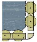 | 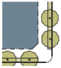 | 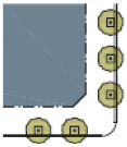 |
| Arrangement | Regular | Clustered | Regular |
| Species | Alternating | Multiple | Multiple |
| Type | Continuous Planter | Continuous Planter | Continuous Planter |
| Width | 5' min. | 5' min. | 5' min. |
| Table 2.3.90.G: Public Planting | |||
| This table shows common street tree types and their appropriateness within the transect zones. The Engineering Standards provides detailed specifications for landscaping along thoroughfares. Additional tree types may be approved by the Administrator. | |||
| Standards | Illustration | Recommended Species | |
| American Beech, American Sycamore, Bald Cypress, Black Gum, Brandywine Red Maple, Ginkgo, Honeylocust, Japanese Zelkova, Lacebark Elm, Laurel Oak, Live Oak, London Plane Tree, Nuttal Oak, Overcup Oak, Pignut Hickory, Pond Cypress, Scarlet Oak, Shagbark Hickory, Shumard Oak, Southern Magnolia, Southern Red Oak, Swamp Chestnut Oak, White Oak, Willow Oak | |||
|
Large Overstory Trees
Placement: Spacing 20'—35' o.c. |  | ||
| American Yellowwood, Carolina Silverbell, Crepe Myrtle, Chinese Pistache, American Hophornbeam, Eastern Redbud, Florida Maple, Flowering Dogwood, Goldenraintree, River Birch, Sweetbay Magnolia, Wax Myrtle | |||
|
Medium and Understory Trees
Placement: Spacing 20'—30' o.c. |  | ||
| Cabbage Palmetto, Canary Island Date Palm, Washingtonia Palm, Zelkova | |||
|
Vertical Trees
Placement: Spacing 15'—25' o.c. |  | ||
| Table 2.3.90.I: Public Lighting | ||||
| Lighting varies in brightness and also in the character of the fixture according to the transect zones. This Table shows the types of light poles and fixtures that may be approved by the Public Works Department assigned to the transect zones. However, the Public Works Department must be included in the selection of light poles and light fixtures. | ||||
| Zone | ||||
| Fixture Type | Cobra Head | Pipe | Post | Column |
| Illustration |  | |||
2.4.10 - Purpose
The purpose of this division is to provide a set of civic space types and their associated standards to use within all zones.
Civic space set-asides are intended for the use and enjoyment of a development's residents, employees, or users. Civic space set-asides serve numerous purposes, including preservation of resource protection areas, other natural areas, ensuring resident access to open areas and recreation, reducing the heat island effect, enhancing stormwater quality, and providing public health benefits.
2.4.20 - Applicability
The standards established in this division shall apply to all proposed development subject to Site Development Plan Review (see Division 8.3 Site Development Review) and Major Subdivision Review (see Division 8.4 Subdivision Review), and shall be considered in combination with the standards for the applicable zone in Article 3 (Specific to Zones) and Article 5 (Supplemental to Zones).
All Agricultural Uses (see Division 4.1 Principal Uses Allowed in Each Zone) shall be exempt from the requirements of this Division.
2.4.30 - Civic Space Types
A.
There are 12 different civic space types defined in Table 2.4.30.A (Civic Space Type Standards). Two of the civic space types, Playgrounds and Community Gardens, may be incorporated into any of the other civic space types, or they may stand alone.
B.
In Table 2.4.30.A (Civic Space Type Standards), the illustration and description of each civic space type are illustrative in nature and not regulatory.
C.
The service area, size, frontage and disposition of elements standards of each civic space type are regulatory.
1.
Service Area. Describes how the civic space relates to the Town as a whole and the area that will be served by the civic space.
2.
Size. The overall range of allowed sizes of the civic space.
3.
Frontage. The relationship along property lines of a civic space to adjacent buildings or lots.
a.
Building. Civic spaces that are listed as having a "building" frontage shall have the fronts of buildings, either attached to the park or across a thoroughfare, facing onto the civic space for a minimum of three quarters of the perimeter.
b.
Independent. Civic spaces that are listed as having an "independent" frontage shall have the fronts of buildings either attached to the park or across a thoroughfare, facing onto the civic space to the maximum extent possible, but may have the side or rear of a building or lot front onto the civic space. The side or rear of a building or lot fronting onto the civic space shall be designed with a secondary frontage and entrance along the civic space.
4.
Disposition of Elements. The placement of objects within the civic space.
a.
Natural. Civic spaces with natural character are designed in a natural manner with no formal arrangement of elements.
b.
Formal. Civic spaces with a formal character have a more rigid layout that follows geometric forms and has trees and other elements arranged in formal patterns.
c.
Informal. Civic spaces with an informal character have a mix of formal and natural characteristics.
D.
Typical Facilities. A list of the typical facilities found within the civic space. This list is not intended to be a complete list of facilities allowed nor is it intended that every civic space would contain each of the facilities listed.
E.
The civic spaces specified in Table 2.4.30.A (Civic Space Type Standards) are allowed by right or with the specified approvals in the designated zones.
| Table 2.4.30.A: Civic Space Type Standards | |||
| Transect Zone | |||
| Civic Space Type | Regional Park | Sport Complex | Community Park |
| Illustration |  | ||
| Description | A natural preserve available for unstructured recreation. | An open space that consolidates heavily programmed athletic fields and associated facilities. | An open space available for unstructured recreation and a limited amount of structured recreation. |
| Location and Size | |||
| Location | |||
| Service Area | Regional | Regional | Multiple Neighborhoods |
| Size | |||
| Minimum | 200 acres | 25 acres | 12 acres |
| Maximum | No Maximum | No Maximum | No Maximum |
| Character | |||
| Frontage | Independent | Independent | Independent |
| Disposition of Elements | Natural, Formal or Informal | Formal or Informal | Informal |
| Typical Facilities | |||
|
Passive and Active
Recreation, Accessory Structure, Drinking Fountains, Community Facility < 7,500 gsf, Paths and Trails |
Passive and Active Recreation, Accessory Structure, Drinking Fountains, Community
Facility < 7,500 gsf, Paths and Trails |
Passive and Active
Recreation, Accessory Structure, Drinking Fountains, Community Facility < 5,000 gsf, Paths and Trails | |
| Table 2.4.30.A: Civic Space Type Standards (continued) | |||
| Transect Zone | |||
| Civic Space Type | Greenway | Green | Square |
| Illustration | 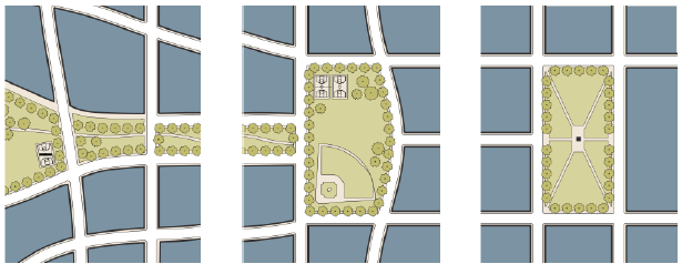 | ||
| Description | A linear open space that may follow natural corridors providing unstructured and limited amounts of structured recreation. | An open space available for unstructured and limited amounts of structured recreation. | An open space available for civic purposes, as well as unstructured and limited amounts of structured recreation. |
| Location and Size | |||
| Location | |||
| Service Area | Multiple Neighborhoods | Neighborhood | Neighborhood |
| Size | |||
| Minimum | 8 acres | 1 acre | ½ acre |
| Maximum | No Maximum | 15 acres | 5 acres |
| Character | |||
| Frontage | Independent or Building | Building | Building |
| Disposition of Elements | Natural or Informal | Informal | Formal |
| Typical Facilities | |||
|
Passive and Active
Recreation, Accessory Structure, Drinking Fountains, Community Facility < 5,000 gsf, Paths and Trails |
Passive and Active
(unstructured or structured) Recreation, Accessory Structure, Drinking Fountains, Community Facility < 5,000 gsf, Paths and Trails |
Passive and Active
(unstructured or structured) Recreation, Accessory Structure, Drinking Fountains, Community Facility < 5,000 gsf, Paths and Trails | |
| Table 2.4.30.A: Civic Space Type Standards (continued) | |||
| Transect Zone | |||
| Civic Space Type | Plaza | Pocket Plaza | Pocket Park |
| Illustration | 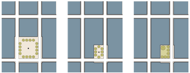 | ||
| Description | A formal open space available for civic purposes and commercial activities. Plazas are typically hardscaped. | A formal open space available for civic purposes and commercial activities. Pocket Plazas are typically hardscaped. | An open space available for informal activities in close proximity to neighborhood residences. |
| Location and Size | |||
| Location | |||
| Service Area | Multiple Neighborhoods | Neighborhood | Neighborhood |
| Size | |||
| Minimum | ½ acre | 4,000 sf | 4,000 sf |
| Maximum | No Maximum | 15 acres | 5 acres |
| Character | |||
| Frontage | Building | Building | Building |
| Disposition of Elements | Formal | Formal | Formal or informal |
| Typical Facilities | |||
|
Passive Recreation,
Accessory Structure, Drinking Fountains, Paths and Trails |
Passive Recreation,
Accessory Structure, Drinking Fountains, Paths and Trails |
Passive Recreation,
Accessory Structure, Drinking Fountains, Paths and Trails | |
| Special Conditions - A Pocket Park shall only be permitted by the Administrator in T3 as a means of fulfilling the required 10% allotment of civic space in developments that are 12 acres or less in size. See Section 2.4.50 (Set Aside Requirement). | |||
| Table 2.4.30.A: Civic Space Type Standards (continued) | |||
| Transect Zone | |||
| Civic Space Type | Playground | Community Garden | Natural Preserve |
| Illustration | 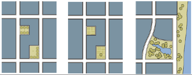 | ||
| Description | An open space designed and equipped for the recreation of children. A Playground should be fenced and may include an open shelter. Playgrounds may be included within other civic spaces. | An open space designed as a grouping of garden plots that are available to nearby residents for small-scale cultivation. Community Gardens may be included within other spaces. | A natural preserve that may contain sensitive natural habitats. Paths and trails may be incorporated into the natural preserve. In T1 natural preserves may include agriculture and crop harvesting. |
| Location and Size | |||
| Location | |||
| Service Area | Neighborhood | Neighborhood | Not Applicable |
| Size | |||
| Minimum | No Minimum | No Minimum | No Minimum |
| Maximum | No Maximum | No Maximum | No Maximum |
| Character | |||
| Frontage | Independent or Building | Independent or Building | Independent |
| Disposition of Elements | Formal or Informal | Formal or Informal | Natural |
| Typical Facilities | |||
|
Accessory Structure,
Drinking Fountains, Paths and Trails |
Accessory Structure,
Drinking Fountains, Paths and Trails | Paths and Trails | |
2.4.40 - Design of Civic Spaces
A.
Design Standards for Civic Space. Land used as civic space shall meet the following design standards:
1.
Location. Where relevant and appropriate, the land shall be located so as to be readily accessible and usable by residents and users of the development. To the maximum extent practicable, a portion of the civic space set-aside should provide focal points for the development.
2.
Configuration.
a.
The land shall be compact and contiguous unless it is used for continuation of an existing trail, or if specific natural or topographic features require a different configuration.
b.
The land shall, to the maximum extent practicable, be located to adjoin, extend, and enlarge any open areas, trails, parks, or other open space resources that exist or are planned adjacent to the development.
3.
Provision in Multi-Phase Developments. In multi-phase developments, civic space set-asides shall be apportioned among the phases such that the total amount of civic space set aside in a phase and any previously approved phases meets the civic space set-aside standard as applied to the total area of the phase and any previously approved phases.
B.
Accessory Structure Standards. All accessory structures within parks and civic spaces, including, but not limited to, rest rooms, open-air pavilions, gazebos, picnic shelters and outdoor theaters, shall not be subject to the physical requirements of the building form standards in Article 3 (Specific to Zones). They shall be designed and furnished to be consistent with the character of the zone in which they are located. Such consistency may require accessory structures to maintain building setbacks, frontage, massing, disposition and character similar to adjacent development as determined by the Administrator.
2.4.50 - Set Aside Requirement
A.
Minimum Set Aside Requirement. Development in all zones shall set aside the minimum amounts of civic space set-aside identified in Table 2.4.50.A (Set-Aside Requirement).
B.
Areas to be Included in Set-Aside Calculations. The features and areas identified in Table 2.4.30.A (Civic Space Type Standards) shall be credited towards the set-aside standards for the purposes of complying with this Section.
1.
Existing Civic Site. Projects located within 1500 feet of an existing civic space type may, at the discretion of the Administrator, receive credit against the required allocation. The space should be of similar type, character, and scale as those identified in Table 2.4.30.A (Civic Space Type Standards), and directly accessible to pedestrians.
2.
Variety and Location. To the maximum extent practicable:
a.
The civic space set-aside requirement shall be fulfilled using multiple types allocated throughout the community;
b.
Civic space types shall transition as per the underlying zone (e.g., a T3 Greenway transitions into a T4 Green); and
c.
Each lot shall be located within a 1,500 foot walk of an existing or proposed civic space.
3.
Pocket Park in T3. A Pocket Park may only be used in T3 for a proposal that is 12 acres or less in size.
C.
Areas not to be Included in Set-Aside Calculations. The following areas shall not be counted as set-asides:
1.
Private Yards. Private yards not subject to a civic space or conservation easement;
2.
Public Street ROW or Private Street Easements. Public road rights-of-way or private street easements, including sidewalks located within those rights-of-way or easements (usable open space within a parkway or greenway may be considered to be a civic space);
3.
Open Parking Areas. Open parking areas and driveways for dwellings;
4.
Land Covered by Structures. Land covered by structures not designated for active recreational or passive civic uses; and
5.
Outdoor Storage Areas. Designated outdoor storage areas.
2.4.60 - Ownership of Set-Asides
A.
Set-aside areas shall be maintained as permanent civic space through one or more of the following options:
1.
The property owner establishes an entity to manage and maintain the set-aside area in a form that ensures long-term maintenance and management;
2.
Conveyance of the land to a property owners' or homeowners' association that holds the land in common ownership and will be responsible for managing and maintaining it for its intended purposes;
3.
Conveyance of the land to a third party beneficiary, such as a nonprofit environmental or civic organization, that is organized for, capable of, and willing to accept responsibility for managing and maintaining the land for its intended purposes;
4.
Dedication of the land to the Town or other appropriate public agency that is organized for, capable of, and willing to accept responsibility for managing and maintaining the land for its intended purposes; or
5.
Where civic space set-aside areas are used for active agriculture and crop harvesting, the property owner manages and maintains the set-aside area.
B.
If a set-aside is to be conveyed to a property owners' or homeowners' association, the association shall be established in accordance with the following:
1.
The landowner shall submit documents for the creation of the property owners' or homeowners' association to the Town for review and approval. The documents shall include the association's bylaws, a legal description of civic space set-aside areas, and all documents governing ownership, maintenance, and use restrictions for the set-aside.
2.
Documents for the creation of the association shall provide that membership in the association is automatic (mandatory) for all purchasers of land, dwelling units, or structures in the development, and their successors in title, and that the association shall have clear legal authority to compel contributions from members to cover their proportionate share of the costs associated with the maintenance of common areas and facilities.
3.
The landowner shall agree that the association shall be established (with all required documents for its creation properly recorded), and operating (with financial subsidization by the landowner or applicant, if necessary, before approval of the first Building Permit for the development.
C.
If the set-aside is to be conveyed to a third party beneficiary, such as a non-profit civic organization, then the conveyance shall include deed restrictions that:
1.
Govern the use, management, and maintenance of the set-asides, consistent with the standards in this Section;
2.
Run with the land in perpetuity; and
3.
Include any other provisions that the Town Attorney deems necessary and appropriate to fulfill the requirements of this Section.
D.
All methods utilizing private ownership shall include deed restrictions, covenants, or other legal instruments that ensure continued use of the land and facilities for their intended uses and provide for the continued and effective management, operation, and maintenance of the land and facilities.
2.4.70 - Maintenance of Set-Asides
A.
Maintenance of civic space set-aside areas shall be the responsibility of the owner(s) of the land making up the areas.
1.
Civic space set-aside areas or other community facilities shall be maintained in accordance with the approved:
a.
Site Development Plan as conveyed in Section 8.3 (Site Development Plan Review);
b.
Special Exception Permit as conveyed in with Section 8.2.50 (Special Exception Permit); or
c.
Subdivision as conveyed in Section 8.4 (Subdivision Process), whichever is appropriate.
2.
Failure to maintain civic space set-aside areas or other community facilities shall be a violation of this Development Code subject to the remedies and penalties in Article 7 (Enforcement).
B.
If the owner of a civic space set-aside area fails to maintain it in reasonable condition, and in accordance with approved plans, and fails to correct deficiencies cited by the Town, the Town shall have the authority to correct the deficiencies.
2.5.10 - Purpose and Intent
A.
Purpose. State law defines subdivisions as land development that divides a tract or parcel of land into two or more lots, building sites, or other divisions.
B.
Intent. Division 2.5 provides specific standards by which subdivisions will be reviewed; and is intended to be used in conjunction with, and reinforce the general development and design standards found throughout Article 2. Adherence to these provisions guarantees that new subdivisions are consistent with the Town's community-oriented character by ensuring the adequate and timely provision of blocks, lots, civic space set-asides, thoroughfares, infrastructure, and other facilities and services.
2.5.20 - Applicability
The following types of activities shall be exempt from the subdivision approval requirements of this Development Code.
A.
The combination or recombination of portions of previously platted lots where the total number of lots is not increased and the resultant lots are equal to the standards of the governing authority;
B.
The subdivision of land into lots of five acres or more where each lot abuts an existing thoroughfare right-of-way or access easement recorded prior to (insert date of adoption);
C.
The division of land into lots for the purpose of sale or transfer to members of one's own immediate family, where no new street is involved, is exempt from the standard submission and review procedures;
D.
The division of land into parcels for conveyance to other persons through the provisions of a Will or similar document, and in the settlement of an intestate estate;
E.
A transfer of title to land not involving the division of land into parcels.
F.
The combination or recombination of entire lots of record where no new street or change in existing streets is involved.
G.
Property trades or swaps between immediately adjacent landowners not resulting in the creation of new parcels of record.
H.
Division of land for the purpose of sale or transfer to an immediately adjacent landowner for the sole purpose of enlarging the adjacent landowner’s property, and not resulting in the creation of new parcels.
I.
The recordation of a plat of land or property for purposes other than the sale of transfer of title to land including the following:
1.
The creation or termination of leases, easements, or liens;
2.
The creation or termination of mortgages on existing parcels of record, approved subdivisions or commercial projects, partly or undeveloped land;
3.
Lot line corrections on existing recorded properties.
4.
The creation, termination or amendment of private covenants or restrictions on land.
Upon request of the Administrator, the owner of the property being divided shall submit a written statement of the occurrence of such divisions as stated in [subsections] A—I above (for information only).
(Ord. No. 2014-14, 9-10-14)
2.5.30 - General Review Standards
A.
General. Applications for subdivisions shall be reviewed and evaluated in accordance with the procedures of Division 8.4 (Subdivision Review), and the standards of this Article.
B.
Subdivision Design. Block and lot layout shall meet the standards established in Division 2.2 (General to All Development).
C.
Streets. New streets shall meet the standards established in Division 2.3 (Thoroughfare Standards).
D.
Civic Spaces. Civic and open spaces shall meet the standards established in Division 2.4 (Civic Space Types).
2.5.40 - Service Standards
A.
Required Improvements. Approval of a final plat shall be subject to the subdivider having installed the improvements hereinafter designated, or having guaranteed, to the satisfaction of the Town, the installation of said improvements.
1.
Street Improvements. Land designated for streets shall be cleared and filled in accordance with the latest edition of the Standard Specifications for Highway Construction, South Carolina State Highway Department as determined appropriate by the Administrator.
2.
Drainage. Adequate storm drainage facilities shall be provided in accordance with the requirements for stormwater in the Town of Port Royal (see Division 5.11 Stormwater), and the Beaufort County BMP Manual, as determined by the Administrator.
3.
Detention and Retention Ponds. Beaufort County BMP Manual. Design data for storage volume and detention outlet requirements shall be submitted to and approved by the Administrator prior to final plan approval.
4.
Water and Sewer Facilities. When a proposed subdivision lies within 500 feet of an existing public water and/or sewer system, the subdivider shall be required to service his subdivision with this system provided that the public agency having authority over the system has agreed to provide such service. A written agreement between the subdivider and the agency indicating the arrangements made for provision of the service shall be submitted with the final application. Such agreement shall clearly state the responsibilities of both parties as they relate to installation and maintenance of the facility(s).
B.
Utility Easements and Lines.
1.
Utility Easements. Easements having a minimum width of eight feet and located along the side or rear lot lines shall be provided as required for utility lines and underground mains and cables.
2.
Utility Lines. All utility lines within a development site shall be installed underground. This provision shall not apply to those lines installed upon an individual single-family or two-family property except where those properties will be served by underground distribution lines located in newly established subdivisions.
3.
Administrative Adjustment. Where overhead facilities are warranted due to exigencies of construction, undue and unreasonable hardship, or other conditions related to the development, the respective utility may request an Administrative Adjustment to allow for overhead facilities prior to final subdivision plat approval (see Section 8.6.10 Administrative Adjustment).
2.5.50 - Survey and Engineering
A.
Installation of Permanent Reference Points and Required Improvements.
1.
Permanent Reference Points. Permanent reference points shall be placed in accordance with the following requirements:
a.
Control monuments. Control monuments shall be placed in the pavement of subdivision streets so that no subdivision lot is more than 800 feet from a control monument. The Control Monuments should be placed in the streets, offset from the center line to avoid sanitary sewer lines, to be approximately half way between the center line and edge of the pavement. Where practical, control monuments shall be placed at points of curvature and points of tangency of curves. The control monument may be poured on the job or be a concrete marker of the type commonly used in the area at least three feet long, and tapered with a twelve inch long 1/4 inch diameter brass or bronze rod embedded in the top. Control monuments shall be placed in a cast iron water main valve type box with a cover flush with the pavement.
b.
Property Marker. A steel or wrought iron pipe, rebar, or the equivalent, not less than one-half (0.5) inches in diameter and at least 30 inches in length shall be set at all property corners and points oil curves, except those located by Monuments.
c.
Accuracy. Land surveys within the Town Limits shall be set at an accuracy of at least 1:7500; beyond the Town Limits an accuracy of not less than 1:5000 is required.
2.5.60 - Improvement Guarantees
To assure the complete installation and maintenance of required improvements, prior to final plat approval, an applicant/developer who wishes to acquire building permits, construct any infrastructure of any type or sell lots before final plat approval may do so through bonding, an irrevocable letter-of-credit and agreement, or other financial security acceptable to the Town. The developer shall provide the Town with an itemized estimate of all necessary improvements in the subdivision as may be needed (i.e., roads, drainage, water, sewer, etc.). If a portion of the improvements have been installed and accepted and/or approved by the Town or other governmental agency having authority over that infrastructure component (i.e., water and sewer), the itemized estimate will be for the improvements from that point to completion of the subdivision. Once the estimates have been approved by the Town, the developer will then present the Town with a bond, surety or other acceptable means of credit for the total of the improvements plus 25 percent in a form acceptable to the Town. The Town will allow separate bonds to be issued to cover specific infrastructure components for water and sewer and/or for other infrastructure that may be operated and maintained by another governmental entity other than the Town. However, the total of all bonds posted must total, at a minimum, 125 percent of the total cost of all infrastructure required to complete the intended improvements.
Prior to issuance of a building or construction permit by the Town for the construction of any infrastructure of any type within the property or development, a bond or legal surety, acceptable to the Town, guaranteeing the completed installation of all required public and infrastructure improvements to the development and other such improvements shown on the engineering drawings for the development or represented in the application [is required]. Such bonds or other surety shall be payable to the Town and equal 125 percent of a registered engineer estimate of construction costs or contractors' executed contracts for subdivision public and infrastructure improvements, whichever is greater. The applicant shall complete, in a manner acceptable to the Town, all improvements including required mechanisms guaranteeing perpetual ownership and maintenance, within 12 months of the date of issuance of a building or construction permit(s) by the Town. Failure to do so will constitute a violation of such permit(s) and terminate the right to continue development, and shall entitle the Town to act on the posted bond, surety or other guarantee(s) and cause the public and infrastructure improvements to be completed by the Town on behalf of the lot purchasers in the development. Extension to the 12-month time period afforded for completion of improvements may be granted one time at the sole discretion of the Town. Such requests must be submitted prior to the expiration date of such permit(s) and accompanied by:
A.
A detailed explanation of why the extension is necessary;
B.
Signed/dated agreement to the extension by all affected lot owners in the development to date;
C.
A detailed description of the amount of work completed, cost remaining for incomplete work and time frame for completion of work; all must be certified by a state professional registered engineer;
D.
Amended bond, or other such surety for incomplete work in an amount of 125 percent of the cost of completion and of sufficient duration to secure the completion of the work.
The Town is hereby granted the power to enforce such bonds by all appropriate legal and equitable remedies. To assure the complete installation and maintenance of required improvements, prior to final plat approval, the Town Council may require a bond, in an amount and with surety and conditions satisfactory to it, providing for and securing to the Town the actual construction, installation and maintenance of such improvements with a period of time specified by the Town and expressed in the bond. The Town is hereby granted the power to enforce such bonds by all appropriate legal and equitable remedies. The Town may accept other means of securing the actual installation and/or maintenance of required improvements.
2.5.70 - Thoroughfare Drawing and Construction Specifications
A.
Design Drawings and Certification. Professional engineers, registered in the state, shall prepare plans, profiles, cross sections, and specifications for all new roads and streets. The engineers shall certify roads/streets are built to comply with the approved plans and specifications. Cross sections shall be developed every 100 feet at intersections and break points in grade. Cross sections shall show travelways, shoulders, ditches, or curb and gutter, if applicable, and utility location.
B.
Construction Specifications for Paved Streets. Street construction specifications for paved streets shall be in compliance with the Town's Engineering Standards.
2.5.80 - Traffic Impact Analysis
A.
Traffic Impact Analysis Required.
1.
Except as outlined below, a traffic impact analysis (TIA) shall be required for any development that would generate more than 50 trips during the peak hour of the adjacent street. A second phase, second subdivision, or addition that takes a property over the trip limitation when taken as a whole shall also require a TIA even though that development does not qualify on its own. The Town staff shall determine whether a TIA is complete. Thorough and complete TIA's are the responsibility of the applicant. Failure by the applicant to provide a complete TIA may result in review delays for their plat or plan. A use shall not be changed to another use permitted in the district without conducting a new TIA, if required.
2.
Development on lots in the downtown districts defined as south of Ribaut Road, bounded by Richmond Avenue on the east and The Battery Creek on the west extending all the way south on the peninsula to and including the Port Redevelopment Property as well as "The Sands," shall not be subject to the requirements of this section.
B.
Traffic Impact Analysis Plan Preparation.
1.
The TIA shall be conducted by an engineer registered in the state that is experienced in the conduct of traffic analysis, and approved by the Town's reviewing staff.
2.
Prior to beginning the traffic impact analysis plan, the applicant shall supply the Town with the following:
a.
A written narrative describing the proposed land use(s), size and projected opening date of the project and all subsequent phases;
b.
A site location map showing surrounding development within one-half ( 1/2) mile of the property under development consideration; and
c.
A proposed site plan or preliminary subdivision plat illustrating access to public or private roads and connectivity to other contiguous developments.
3.
Town reviewing staff will rely upon the most current edition ITE trip generation manual or any alternative acceptable to the engineering department, and available information on land use, travel patterns and traffic conditions, and after consulting with the SCDOT will supply in writing to the applicant and/or his engineer the parameters to be followed in the study including the directional split of driveway traffic, trip distribution, background traffic growth rate, previously approved but not completed projects and the intersections to be analyzed along with any associated turning movement counts which are available or discussed and approved by the reviewing staff.
C.
Plan content.
1.
All phases of a development are subject to review, and all traffic plans for the entire development shall be integrated with the overall traffic analysis. A traffic impact analysis plan for a specific phase of development shall be applicable to the phase of development under immediate review. However, each phase of development shall expand and provide detailed analysis at the development plan stage beyond the estimates provided for at the concept plan or master plan stage.
2.
The adequacy of the roads to which the development takes access shall be assessed in the TIA. Recommendations for improvements shall be made. The relative share of the capacity created shall be broken down as follows: development share, other developments share, any existing over capacity, and capacity available for future growth.
3.
Residential development, residential care facilities, hospitals, hotels and resort-oriented developments shall submit an emergency evacuation analysis (EEA), as part of the TIA. The EEA shall indicate how the proposed development utilizes the county's prescribed evacuation routes, as shown in the Beaufort County Comprehensive Plan. The transportation planner or traffic engineer preparing the report shall indicate the effect of the proposed development upon existing evacuation times for that portion of the county. The EEA shall be reviewed by the Beaufort County Director of Public Safety prior to submittal as part of the TIA.
4.
The following elements shall be included in a traffic impact analysis plan:
a.
A site plan or subdivision plat identifying accesses to and from existing or proposed streets and intersections.
b.
Description of the proposed development, including the type of proposed land use, the number of residential units by type, the number of existing and proposed lots, the type of proposed nonresidential development and the amount of such development measured by gross floor area or other appropriate unit of measurement, the general size and type of accessory development or facilities, and, for nonresidential development, adequate information to identify the appropriate land use category for trip generation. The traffic impact analysis plan will be projected to a date mutually agreed upon by the applicant and staff.
c.
Projected vehicular trips to and from the completed development during a.m. and p.m. peak hour. Trip rates shall be taken from ITE manual, provided, however an applicant may elect to perform, at his own expense, a trip generation study which may be submitted as part of the traffic impact analysis plan. Such trip generation study shall be subject to the review and verification of the Town reviewing staff. For proposed uses not specifically listed in the ITE manual, and for which a trip generation study has not been performed, the town engineer, in consultation with the traffic engineer, shall determine the most appropriate trip generation rate. The Town reviewing staff shall make the determination of the appropriate trip generation rate, from whatever the source. The percentage of pass-by trips, if used in the plan, shall be included, as well as the source of the percentage of pass-by trip information.
d.
A written narrative setting forth the assumptions upon which any projection, made in developing the traffic impact analysis plan, shall be included in the analysis. If the assumptions are derived from the ITE manual, the materials shall be referenced and properly cited. If the assumptions are not from the ITE manual, appropriate excerpts from other reliable transportation planning resources shall be included in the study and reasons underlying the assumptions shall be stated in the narrative.
e.
The TIA shall review access to the site. The adequacy of the entrance design shall be evaluated and recommendations made of acceleration and deceleration lanes, left turn lanes, or signalizations shall be part of the TIA.
f.
The TIA shall review the number and types of curb cuts that are permitted. In particular, the TIA shall assess the connection of the property to adjoining properties. Where the use, scale of development, or size of adjoining properties is such that trips would be anticipated between the proposed use and the other properties the TIA shall make recommendation on interconnections. The TIA shall recommend interconnections to provide a smooth flow of traffic between uses along arterials and collector roads to ensure that as much traffic as possible uses secondary roads rather than major roads for short trips.
g.
The traffic impact analysis shall be based on intersection analysis procedures for signalized intersections as identified in the most current edition of the transportation research board's highway capacity manual and/or the last update that analyzes and emulates these procedures by means of computer software if available. The results of any required analysis/computer analysis shall, at a minimum, indicate compliance or variance from the traffic goals in subsection (j). The traffic impact analysis plan will be projected to a date mutually agreed upon by the applicant and staff.
h.
The intersections that must be analyzed in the study are identified to be as follows:
5.
Any intersection that serves as a development's point of access. This will include intersections of public and/or private roads with major arterials, and driveways offering direct access.
6.
The first major intersection as identified by the Town's designated traffic engineer on both sides of the development's point of access.
7.
Other intersections on major arterials if development generates more than 50 a.m. or p.m. peak hour trips to that intersection or when in the opinion of the TRC there is a potential for a significant impact to the intersection's level of service from site related
8.
Traffic, or Intersection Demand Critical.
9.
Unsignalized intersections and access drives shall be considered if development impacts are anticipated. The plan must include the results of an analysis of the operating conditions of critical intersections and/or all intersections identified in the concept plan. The analysis shall reflect the projected condition of these intersections and movements, based on the scheduled opening date of the development. Other phases of the development if they can be reasonably determined shall be considered as well.
D.
Mitigation Plan Required. If the initial analysis indicates that the Town's adopted traffic service level goals will be exceeded, a mitigation plan must be prepared based on additional analysis. The mitigation plan must show how the Town's service level goals are addressed as mitigated. Applicants will be responsible to mitigate the traffic impacts at any intersection effected by a proposed development.
1.
If a traffic signal is recommended, the analysis shall provide information that does the following:
a.
Clearly indicates the need for a traffic signal.
b.
Assesses the ability of other existing or planned or proposed public roads to accommodate the new traffic at a location other than the main highway in the vicinity of the proposed development.
c.
Describes in detail how a specific development will affect the study area transportation system.
d.
Provides documentation of appropriate South Carolina Manual of Uniform Traffic Control Devices (SCMUTCD) signal warrant satisfaction.
e.
Gives design geometry of the private road that is consistent with that of public road intersections including curbs, appropriate lane widths, pavement markings and vertical alignment. Other roadway factors to be considered include, but are not limited to, speed, type of highway, grades, sight distance, existing level of service, conflicting accesses, and the effect of future traffic signal systems.
f.
Provides an approach throat length for the road to guarantee the movement of vehicles entering the site will not be impeded by on-site conditions, and ensure that all signal spacing requirements are adequately met.
2.
A traffic signal progression analysis is required if the proposed location is closer than the SCDOT standards given the presence of existing signals or the possible existence of future signals proposed as part of a highway signal system.
3.
The desirable spacing of signalized intersections on principal arterials is the SCDOT, county, or Town standards. The Town's reviewing staff may recommend to SCDOT the installation of a traffic signal at locations where using SCDOT standards spacing is inappropriate due to: topography, existing or proposed road layout; documented accident history; unique physical constraints; existing or proposed land use patterns; or requirements to achieve specific objectives for highway segment designations as shown in any locally adopted land use or transportation plan or approved Town or county transportation plan or approved transportation policy.
4.
Signal spacing concerns may be ameliorated in the following ways:
a.
A proposed private road that may otherwise be considered for the installation of a traffic signal may be replaced by an onsite route or a frontage road that directs traffic to or from a nearby public road;
b.
A private road that is being considered for traffic signal installation may be required to connect to the existing or planned local road system to allow uses of surrounding properties;
c.
An existing or proposed intersection may be relocated; or
d.
A shared private road may be required to serve the needs of the multiple properties.
5.
A traffic signal progression analysis for all new, revised or planned traffic signal systems on state highways shall be performed using methods, models, computer software, data sources, roadway segment length, and assumptions approved by the Town's reviewing staff. The roadway segment, analyzed to the extent possible, shall include all traffic signals in the existing or future traffic signal system. The progression analysis shall:
a.
Demonstrate acceptable existing and future traffic signal systems operation that may include the morning peak, evening peak, midday period, and other appropriate time period during any day of the week adjusted for peak season, for cycle lengths and travel speeds approved by the Town's reviewing staff;
b.
Provide for a progressed traffic band speed no more than five mph (eight km/h) below the existing posted speed for both directions of travel during the off-peak periods, nor more than ten mph (16 km/h) below the existing posted speed during peak periods. Approval by the Town's reviewing staff is required where speeds deviate more than the above;
c.
Demonstrate sufficient vehicle storage is available at all locations within the traffic signal system without encroaching on the functional boundaries of adjacent lanes and signalized intersections. The functional boundary of an intersection shall be determined in discussion with the Town's reviewing staff based on existing or projected conditions;
d.
Provide a common cycle length with adequate pedestrian crossing times at all signalized intersections; and
e.
Provide a progression bandwidth as large as that required, or as presently existing, for through traffic on the federal or state highway at the most critical intersection within the roadway segment. The most critical intersection is the intersection carrying the highest through volume per lane on the federal or state highway.
6.
The traffic signal progression analysis shall be supplemented by a traffic engineering report that also considers highway capacity and safety of the roadway segment under consideration. Traffic volumes, intersection geometry and lane balance considered at all locations shall be appropriate for the present and future conditions. Present and future conditions are usually considered to include the year of completion, and five years into the future.
7.
A clear and concise summary of recommended improvements that can serve as an executive summary is required.
E.
Traffic Impact Analysis Plan Review. The Town's reviewing staff shall review all traffic impact analysis plans as part of the initial approval for the concept plan or master plan. Final traffic impact analysis plans shall be approved at the development plan phase.
F.
Application. A traffic impact analysis plan shall be submitted to the Town's reviewing staff. Coordination with other entities in the county government or South Carolina Department of Transportation (SCDOT) shall be the responsibility of the Town.
G.
Action on Traffic Impact Analysis Plan. The Town's reviewing staff must first approve the TIA in regard to completeness and accuracy. Following review of the required impact analysis plan, reviewing staff shall recommend action as follows:
1.
Approval of the traffic impact analysis as submitted;
2.
Approval of the traffic impact analysis plan with conditions or modifications as part of the development review and approval process. An acceptable traffic impact analysis plan with traffic mitigation measures may include the reduction of the density or intensity of the proposed development; phasing of the proposed development to coincide with state and/or county-programmed transportation improvements; applicant provided transportation improvements; fees in lieu of construction, or any other reasonable measures to ensure that the adopted traffic service level goals are met. If mitigation is required, it shall be required as a condition of any approval from the Town.
H.
Timing of Implementation. If a traffic mitigation program is part of an approved traffic impact analysis plan, the developer may be required to place a performance bond on all traffic mitigation improvements required as a result of his project. This requirement may arise if the timing of the improvements needs to be synchronized with other scheduled improvements anticipated for the area.
I.
Responsibility for Costs of Improvements. The costs of implementation of an approved mitigation program shall be the responsibility of the applicant. No certificates of zoning compliance or building permits shall be issued unless provisions of the transportation impact analysis are met.
J.
Traffic Goals. The average stop time delay in seconds per vehicle for each intersection determined to be critical to the traffic impact analysis for the proposed development shall be compared to the Town's adopted traffic service level goal of "D" for the average delay for all vehicles at any signalized intersection during the a.m. and p.m. peak hours.