Tifton City Zoning Code
Appendix 1
TECHNICAL STANDARDS MANUAL FOR STREETS, DRAINAGE, AND STORMWATER MANAGEMENT
Sec. 1. - Introduction.
The following technical criteria and design standards shall be used as a supplement to the City of Tifton Unified Land Development Code (ULDC) and all other related City of Tifton Ordinances. These may include, but are not limited to: the City of Tifton Subdivision Ordinance, Flood Hazard Reduction Ordinance, Soil Erosion and Sedimentation Ordinance, Utilities Ordinance, Zoning Ordinance, and all other ordinances which regulate the development of all land, public and private, within unincorporated City of Tifton.
The following technical standards shall be used as the minimum design criteria for development or redevelopment within City of Tifton. Development and redevelopment includes all residential, commercial, industrial or institutional development performed within the County's jurisdiction, as described in Sections 1.1 and 1.2 below. Whenever there is a discrepancy between minimum standards or dimensions required under this Technical Guidance Document and those contained within other City of Tifton Ordinances or regulations, the most restrictive or the Staff Development Review Committee's (SDRC) interpretation shall apply.
1.1 Applicability.
This Technical Standards Manual shall be applicable to all land development, including, but not limited to, site plan applications, subdivision applications, and grading applications, unless exempt as outlined below. These standards apply to any new development or redevelopment site that meets one or more of the following criteria:
1.
New development that involves the creation of 5,000 square feet or more of impervious cover, or that invoices other land development activities of one acre or more.
2.
Redevelopment that includes the creation, addition or replacement of 5,000 square feet or more of impervious cover, or that involves other land development activity of one acre or more.
3.
Any new development or redevelopment, regardless of size, that is defined by the SDRC to be a hotspot land use. A hotspot is any area located within a drainage basin that is known to have historical drainage issues related to flooding.
4.
Land development activities that are smaller than the minimum applicability criteria in items 1 and 2 above if such activities are part of a larger common plan of development, even though multiple, separate and distinct land development activities may take place at different times on different schedules.
1.2 Exemptions.
The following activities are exempt from these standards:
1.
Individual single-family or duplex residential lots that are not part of a subdivision or phased development project.
2.
Additions or modifications to existing single-family or duplex residential structures.
3.
Agricultural or silvicultural land management activities within areas zoned for those activities, unless located in hotspot areas, as defined in Section 1.1 above.
4.
Repairs to any storm water management facility or practice deemed necessary by the SDRC or County's Engineer.
Sec. 2. - Definitions.
2.1 Interpretation of certain terms or words.
Except As specifically defined herein, all words in the Technical Standards Manual have the customary dictionary definitions. For the purpose of these standards, certain words or terms used herein are defined as follows:
Words used in the present tense include the future tense. Words used in the singular include the plural, and words used in the plural include the singular. All pronouns used herein shall be deemed to include the masculine, the feminine and non-personal entities.
Whenever reference is made in the Technical Standards to another section of this manual, all parts of that section are deemed to be included in such reference.
The word "shall" is always mandatory.
The word "may" is permissive.
The word "person" includes a firm, association, organization, partnership, trust, company, or corporation as well as an individual.
2.2 Definitions.
The definitions set forth in the Tifton-City of Tifton Unified Land Development Code (ULDC) are incorporated herein by reference and shall have the same definitions herein as set forth in the ULDC. Other important definitions include:
Development or Land Development means any land change, including, but not limited to, clearing, digging, grubbing, stripping, removal of vegetation, dredging, grading, excavating, transporting and filling of land, construction, paving and any other installation of impervious cover.
Redevelopment means a land development project on a previously developed site, but excludes ordinary maintenance activities, remodeling of existing buildings, resurfacing of paved areas, and exterior changes or improvements which do not materially increase or concentrate storm water runoff, or cause additional nonpoint source pollution.
Sec. 3. - General provisions.
3.1 Plan review and approval.
The development of land within City of Tifton, Georgia shall require the submittal of plans, plats, or construction drawings as may be required by the ULDC and these Standards to the City of Tifton Staff Development Review Committee (SDRC). Approval of these documents must be received prior to the initiation of any development activities.
3.2 Staff development review committee.
As outlined in the ULDC, the Staff Development Review Committee (SDRC) is responsible for the review and approval of development plans to which this Technical Standards Manual applies. All applications for development within unincorporated City of Tifton must be submitted to the SDRC for review and shall include all required applications, application fees, plats, development and building plans, and reports as necessary. Refer to the ULDC or other applicable ordinances for additional details of submittal requirements.
3.3 Responsibility and liability.
Approval of plans, plats, or construction drawings by City of Tifton shall not imply nor transfer acceptance of responsibility for the application of the principals of engineering, surveying, architecture, landscape architecture, or any other profession, from the professional corporation or individual under whose hand or supervision the plans, plats, or construction drawings were prepared and sealed.
3.4 Design professional.
All development plans submitted to the County for review must conform to the applicable standards and specifications established herein by the County, and must be prepared, signed, and sealed by a Georgia registered design professional. The design professional must be a Professional Engineer, Registered Architect, Registered Land Surveyor, Registered Landscape Architect or other qualified design professional licensed by the State of Georgia.
3.5 As-builts for subdivisions.
Before final plat approval or the issuance of a building permit, the Owner of a land development must submit as-built drawings to the County for review and final approval. The owner shall submit one full size (size D - 24"x36") or larger set of drawings and a set of plans in electronic format. As-builts shall include all utilities, roads, storm drainage and detention pond structures, or other information as required by the SDRC. As-builts shall be certified by a registered design professional stating that the all improvements have been built in accordance with the plans and specifications.
Sec. 4. - Requirements.
4.1 Required improvements.
Except as otherwise provided by the ULDC, a Developer shall provide, install and pay for the following improvements to serve their development:
A.
Water supply and distribution
B.
Sanitary sewage collection
C.
Sewage disposal systems
D.
Road grading and surfacing
E.
Storm drainage
F.
Road name signs
G.
Electricity
H.
Natural gas (optional)
I.
Traffic control devices
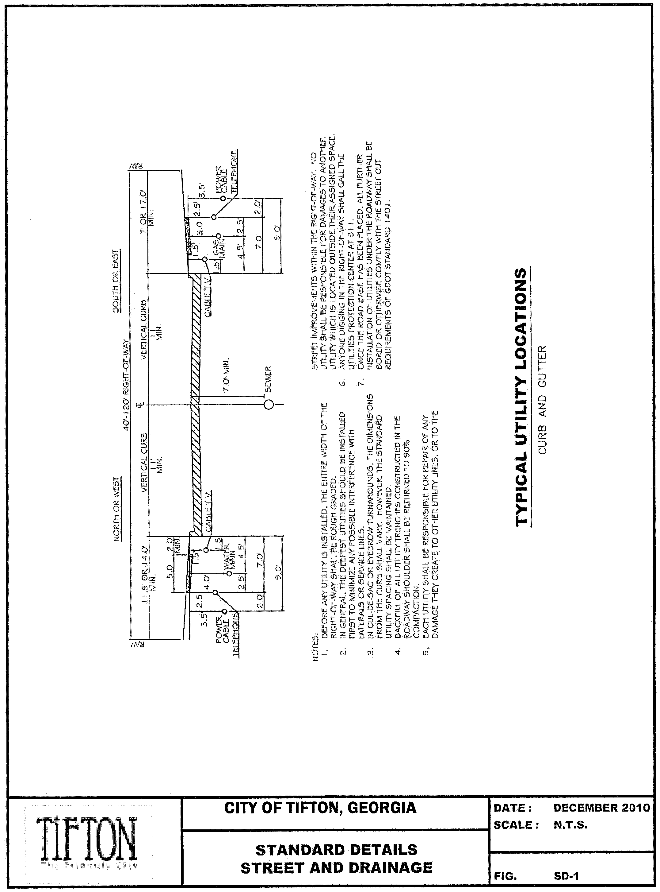
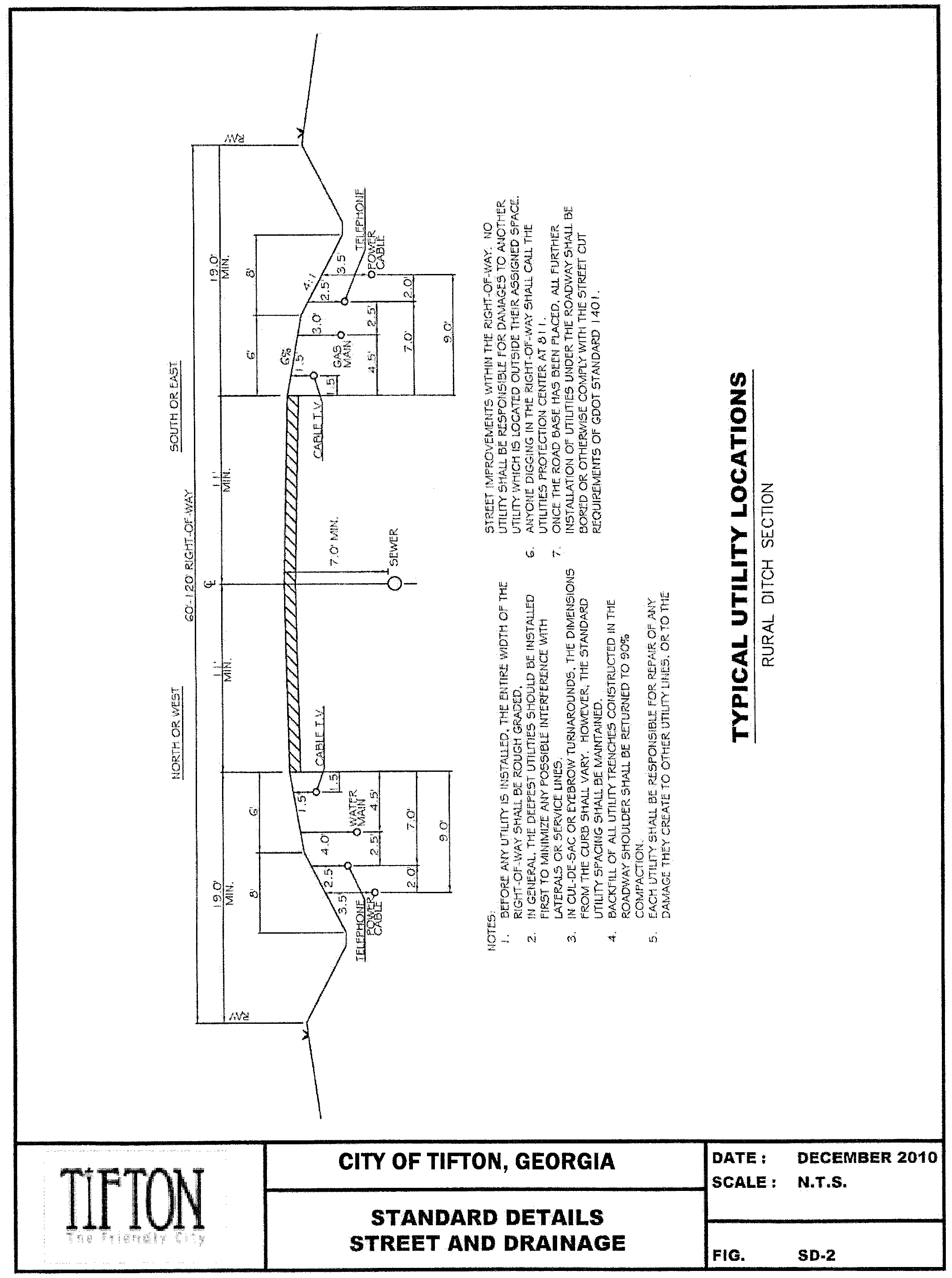
Utilities shall be located where possible in accordance with the proposed utility location detail.
4.2 Easements.
Easements having a minimum width of twenty (20) feet and located along the side or rear lot line shall be provided as required for utility lines, underground mains, cables and drainage.
Maintenance easements shall be provided when deemed necessary by the SDRC. When a subdivision or land development is traversed by a watercourse, drainage way, channel, or intermittent stream, a stormwater or drainage easement of at least twenty-five (25) feet shall be provided from the top edge of each bank. Such easements may be used as a location for Pedestrian Ways, bikeways and other amenities which do not conflict with the basic maintenance function of such easements.
4.3 Permits.
As outlined in the ULDC, a developer may be required to obtain the following permits from the County for development within City of Tifton:
• Land Disturbance Activity Permit
• Subdivision Permit
• Building Permit
• Driveway Permit
• Water System Extension Permit
• Sanitary Sewer Extension Permit
• Applicable Zoning Permits
• Applicable Variances
The developer shall consult the SDRC on any other County permits that may be required which are not listed herein.
Nothing in these Technical Standards shall impose any obligation on City of Tifton to obtain or assist in obtaining permits, approvals, and/or clearances from other local, state or Federal agencies having jurisdiction over elements of a project. It is solely the developer's responsibility to obtain all such required permits, approvals, and/or clearances. The developer shall furnish the County with copies of all such permits, approvals and/or clearances before authorization to proceed with development is requested.
Sec. 5. - Street design standards and specifications.
5.1 Design standards.
All roads and bridges constructed in City of Tifton shall be designed in accordance with the latest editions of the American Association of State Highway and Transportation Officials (AASHTO) design guides and specifications as well as Georgia Department of Transportation (GDOT) Standards except as provided in these technical standards.
5.2 Street classification.
Six (6) functional classifications are identified by the City of Tifton Subdivision Ordinance and the Tifton-City of Tifton Thoroughfare Plan. Any street not indicated on the thoroughfare plan will be classified by the SDRC. The six classification categories are as follows:
A.
Major Arterial Street: A street which is designated as such on the Thoroughfare Plan and which is intended to provide, within an identified planning period, swift, safe and convenient traffic movement within and through the county. A major thoroughfare.
B.
Secondary Arterial Street: A street which is designated as such on the Thoroughfare Plan and which is intended to provide easy and convenient traffic movement within the county.
C.
Collector Street: A street which is designated as such on the Thoroughfare Plan and which is intended to collect traffic from local streets and direct it safely to secondary major streets.
D.
Dead-end Streets: A street having only one end open for access to another street, and the other end being abruptly terminated with no turnaround (excludes cul-de-sacs). Future development of dead-end streets is not permitted within City of Tifton.
E.
Marginal Access Street: A street generally parallel to and adjacent to an arterial street providing access to abutting properties and protection from through traffic.
F.
Local Street: A street used for local circulation in areas providing access to abutting property. Local streets serving residential areas shall be designed to discourage use by through traffic.
5.3 Minimum right-of-way widths and dedication requirements.
The Thoroughfare Plan illustrates the functional classification of streets and the general location of future arterial and collector streets in the County. The right-of-way dedication requirements expressed below shall correspond to the functional classifications illustrated on the Thoroughfare Plan. Should a proposed subdivision adjoin an existing unimproved roadway, the developer shall dedicate additional right-of-way to meet the minimum right-of-way requirement for the applicable functional classification of the adjoining street.
Table 5.3.a. Minimum right-of-way and pavement widths
*local roadways are also known as rural minor roadways.
If a median is included as part of the site plan, minimum median width for a divided street shall be at least ten (10) feet measured from back of curb to back of curb.
The right-of-way width shall be sufficient to allow the required minimum pavement width, curb and gutter or ditch, utilities and a minimum ten feet separation of water mains from sanitary and storm sewers.
(Ord. No. 2019-11, 3-18-2019)
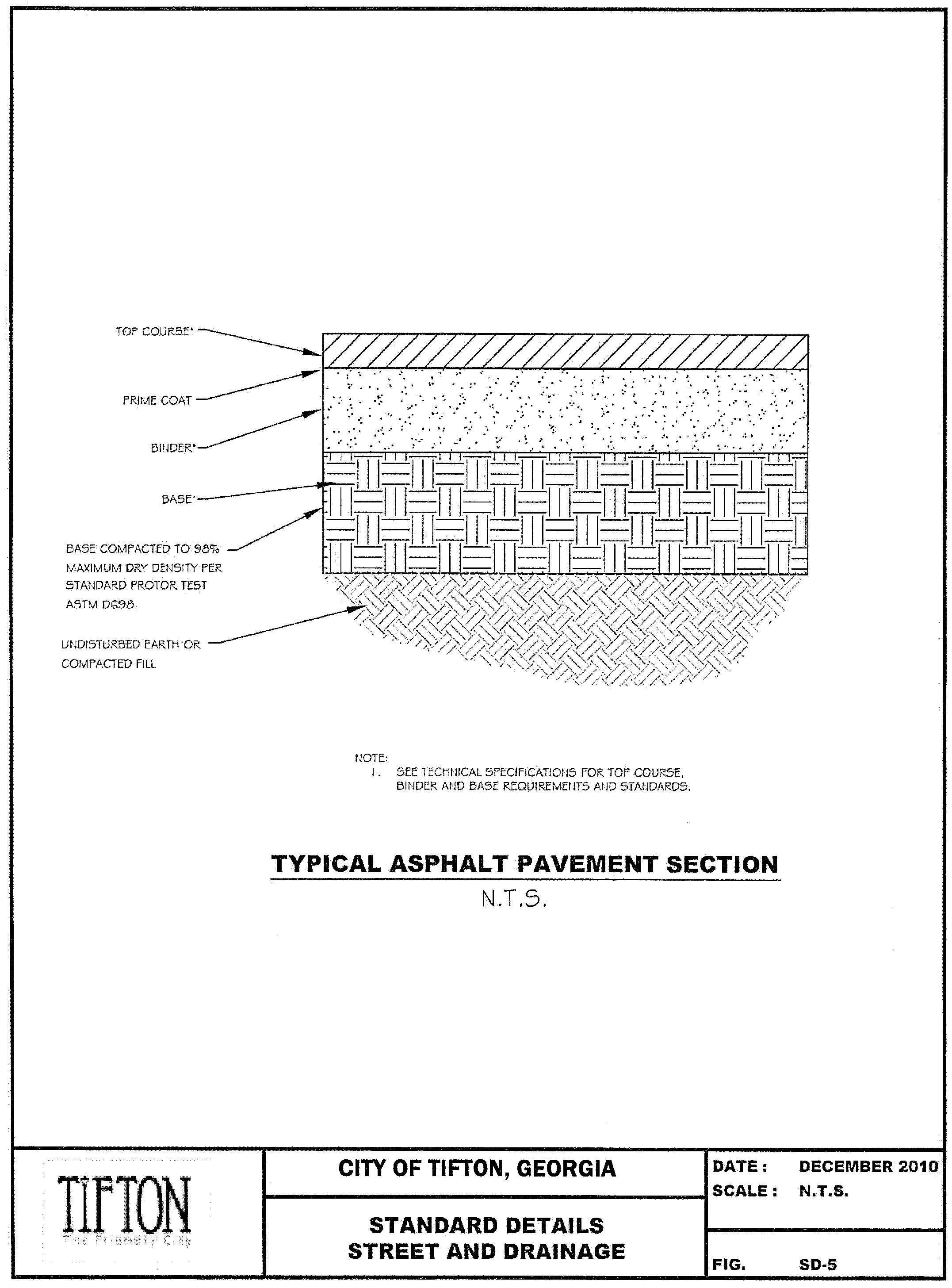
5.4 Roadway sectional composition.
The applicable standard shall be based on functional classification and the predominant zoning through which a street passes. See latest edition of the Georgia Department of Transportation (GDOT) Standard Specifications for the Construction of Roads and Bridges for specifications of referenced asphaltic concrete types. For all street classifications, before asphalt pavement is placed, a bituminous prime shall be applied to the base material in accordance with GDOT specifications. Application rate shall be a minimum of 0.15 gallons and a maximum of 0.20 gallons per square yard.
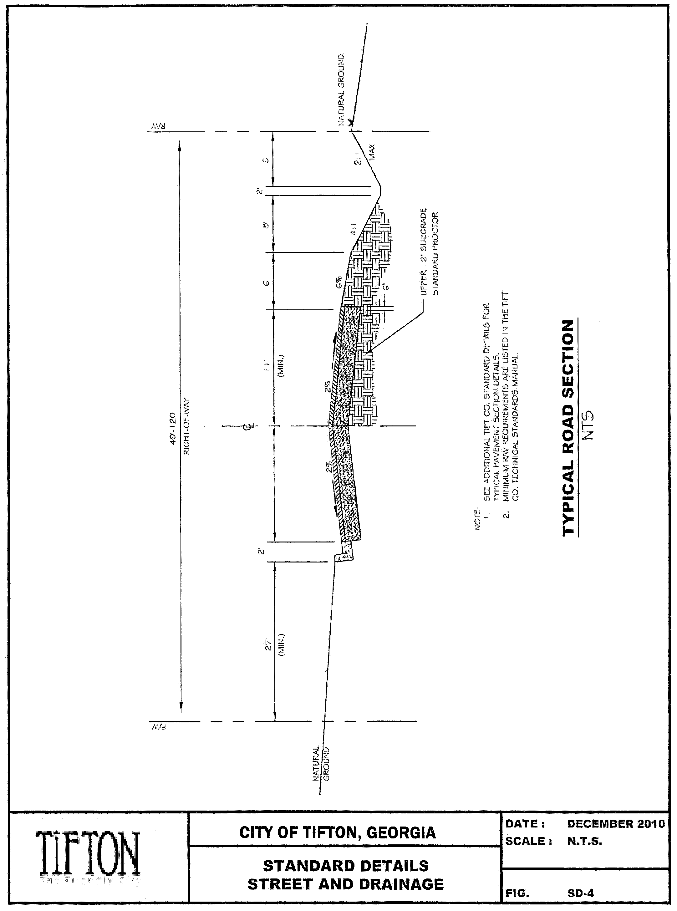
For typical roadway cross sections with asphalt pavements or concrete pavements, see the attached typical details.
5.4.1 Local Streets.
• 1½" - 12.5 mm Asphalt SuperPave (165 lbs/sq. yd.) top course or
1½" - 9.5 mm Asphalt SuperPave (165 lbs/sq. yd.) top course
• 6" - Graded aggregate base (GAB) or
6" - Soil cement (Soil cement shall be mixed in place)
Base shall be compacted to 98% maximum dry density per standard proctor test ASTM D698.
5.4.2 Collector Streets (for residential, office, institutional, and commercial developments).
Asphalt Pavement:
• 1½" - 12.5 mm Asphalt SuperPave (165 lbs/sq. yd.) (top course)
• 2" - 19 mm Asphalt SuperPave (220 lb/sq. yd.) (binder)
• 6" - Graded aggregate base* (GAB) or
6" - Soil cement** (Soil cement shall be mixed in place)
Base shall be compacted to 98% maximum dry density per standard proctor test ASTM D698.
* Graded aggregate base may include crushed concrete, limerock or granite.
**For soil cement, a mix design by a licensed Geotechnical Engineer in the state of Georgia must be submitted to the SDRC's Engineer for approval.
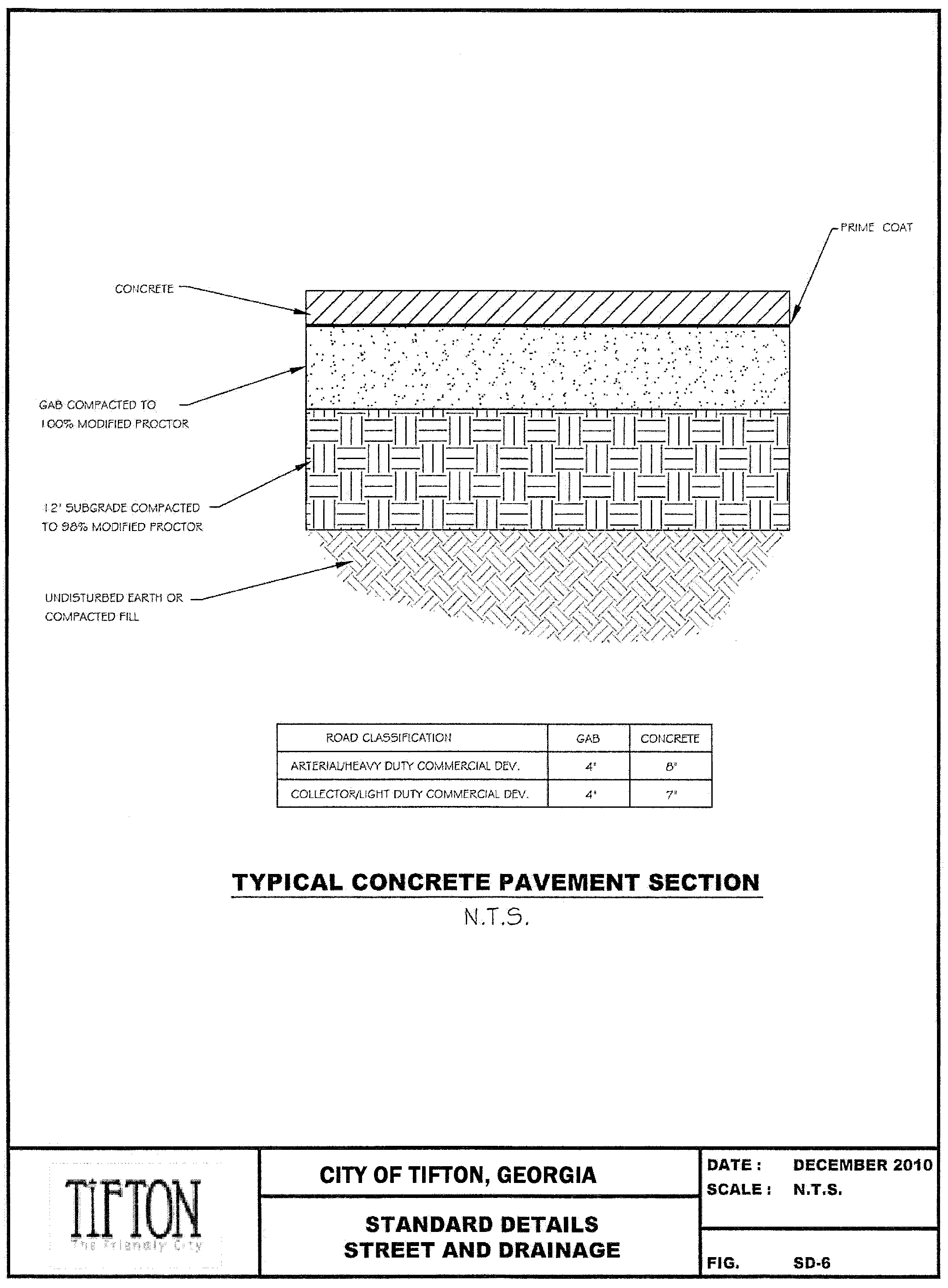
Concrete Pavement:
• 7" - Concrete pavement per specifications detailed in Section 5.5.5.
• 4" - Graded aggregate base course compacted to 98% maximum dry density per standard proctor test ASTM D698.
5.4.3 Arterial Roads (including industrial roads).
Asphalt Pavement:
• 1½" - 12.5 mm Asphalt SuperPave (165 lbs/sq. yd.) (top course)
• 2" - 19 mm Asphalt SuperPave (220 lb/sq. yd.) (binder)
• 3" - Asphaltic base 25mm Asphalt Superpave
• 8" - Graded aggregate base* (GAB) or
8" - Soil cement** (Soil cement shall be mixed in place)
Base shall be compacted to 98% maximum dry density per standard proctor test ASTM D698.
* Graded aggregate base may include crushed concrete, limerock or granite.
**For soil cement, a mix design by a licensed Geotechnical Engineer in the state of Georgia must be submitted to the SDRC's Engineer for approval.
Concrete Pavement:
• 8" - Concrete pavement per specifications detailed in Section 5.5.5
• 4" - Graded aggregate base course compacted to 98% maximum dry density per standard proctor test ASTM D698.
5.4.4 Commercial Development.
A.
Heavy Duty
Asphalt Pavement:
• 2" - 12.5 mm Asphalt SuperPave (220 lbs/sq. yd.) (top course)
• 3" - 19 mm Asphalt SuperPave (330 lbs/sq. yd.) (binder)
• 8" - Graded aggregate base* (GAB) or
8" - Soil Cement** (Soil cement shall be mixed in place)
Base shall be compacted to 98% maximum dry density per standard proctor test ASTM D698.
* Graded aggregate base may include crushed concrete, limerock or granite.
**For soil cement, a mix design by a licensed Geotechnical Engineer in the state of Georgia must be submitted to the SDRC's Engineer for approval.
Concrete Pavement:
• 8" - Concrete pavement per specifications detailed in Section 5.5.5.
• 4" - Graded aggregate base course compacted to 98% maximum dry density per standard proctor test ASTM D698.
B.
Light Duty
Asphalt Pavement:
• 2" - 12.5 mm Asphalt SuperPave (220 lbs/sq. yd.) (top course)
• 8" - Graded aggregate base* (GAB) or
8" - Soil Cement** (Soil cement shall be mixed in place)
Base shall be compacted to 98% maximum dry density per standard proctor test ASTM D698.
* Graded aggregate base may include crushed concrete, limerock or granite.
**For soil cement, a mix design by a licensed Geotechnical Engineer in the state of Georgia must be submitted to the SDRC's Engineer for approval.
Concrete Pavement:
• 7" - Concrete pavement per specifications detailed in section 5.5.5.
• 4" - Graded aggregate base course compacted to 98% maximum dry density per standard proctor test ASTM D698.
5.5 Subgrade, base and pavement material and construction specifications.
5.5.1 Testing. All tests and data described below shall be conducted or provided and paid for by the paving contractor of developer. Test results shall be submitted to the SDRC's Engineer for review and/or approval. Testing shall be performed by a licensed Geotechnical Engineer (or his/her authorized representative working under his/her direct supervision) in the State of Georgia who has been prequalified by the GDOT for Area Classes 6.04a or 6.04b and must be approved by the SDRC. A list of GDOT prequalified consultants is available on the GDOT's website.
5.5.2 Subgrade. All fill materials proposed for use in roadway construction that could affect the performance of pavements, curbs or utilities should meet the given requirements for structural fill. Structural fill material should be free of organics, deleterious material, debris and rocks greater than six (6) inches. Fill soils should have a plasticity index less than 20, a liquid limit less than 40 and a Standard Proctor (ASTM D698) dry density of at least 100 pcf.
Embankments shall be constructed in eight to twelve inch lifts. Individual lifts shall be compacted using sheep's foot rollers, vibratory compactors, pneumatic tire rollers or other equipment capable of obtaining the required compaction. The surface of the completed subgrade shall be bladed to a smooth and uniform texture. The centerline profiles shall conform to the established elevations with an acceptable tolerance of +/- ½ inch. The acceptable tolerance under a template conforming to the designed cross-section shall be +/- ¼ inch.
Soil density tests shall be performed on roadway fills four (4) feet in height and greater. The compaction tests will be performed to within twelve (12) inches of the final grade of the subgrade. For the fills requiring compaction tests they shall be compacted to ninety-eight (98) percent of maximum dry density per the standard proctor test (ASTM D698, AASHTO T99). One set of compaction tests shall be performed on every other twelve (12) inch lift at one hundred-foot intervals along the roadway fill section. A licensed Geotechnical Engineer in the state of Georgia (or his/her authorized representative working under his/her direct supervision) shall perform the tests. Where the subgrade compaction is determined to be less than the required degree, the developer shall remove, replace, and/or recompact the section in question, or use other means approved by the Engineering Department, until the density is determined to meet the required limit. Copies of all test results shall be submitted to the SDRC.
The compaction of the top twelve (12) inches of the subgrade shall be inspected by proof rolling. The subgrade shall have sufficient stability to support any and all types of construction equipment used to construct roadway without "pumping" (vertical and/or horizontal displacement of the subgrade). The "proof-roll" compaction inspection of the subgrade shall be by a vehicle with a minimum gross vehicle weight of 24,000 pounds, fully loaded with a minimum of 16 tons (32,000 lbs) of graded aggregate (54,000 lbs total weight minimum). The weight of the proof-roll inspection vehicle and the accompanying load shall be shown on a printed "load-out" ticket from a reputable quarry. Representatives of the SDRC shall be present and approve all subgrades. The contractor, at the contractor's expense, shall correct any areas not passing the proof-roll inspection.
The contractor shall be responsible for contacting the SDRC at least three (3) days prior to any proof-roll to schedule an on-site inspection of the proof-roll. Failure to perform all testing and arrange the on-site inspection may lead to a denial of acceptance of the road by the County. It may also lead to additional testing requirements at the contractor's expense.
5.5.3 Graded Aggregate Base (GAB). GAB may include limerock, crushed concrete base or granite. GAB materials should be tested for GDOT compliance by a licensed Geotechnical Engineer (or their authorized representative working under their direct supervision) in the State of Georgia who shall be approved by the SDRC.
A.
Placement of the base material shall be inspected and approved by the SDRC as specified below. The paving contractor/developer is responsible for requesting such inspections at least three (3) days in advance, and placement of base shall not be done until such inspections have been scheduled.
B.
The compacted base course (graded aggregate or crusher run) shall have sufficient stability to support any and all types of construction equipment used to construct the roadway without "pumping" (vertical and/or horizontal displacement of base due to any number of factors including too much water, not enough compactive effort, etc.), regardless of compaction. The "proof-roll" compaction inspection of the graded aggregate base shall be by a vehicle with a minimum gross vehicle weight of 24,000 lbs, fully loaded with a minimum of 16 tons (32,000 lbs) of graded aggregate (54,000 lbs total weight minimum). The weight of the proof-roll inspection vehicle and the accompanying load shall be shown on a printed "load-out" ticket from a reputable quarry. A licensed Geotechnical Engineer in the State of Georgia (or their authorized representative working under their direct supervision) must certify all proof-roll compaction inspections. A representative of the SDRC shall be present for all proof-roll compaction tests of all graded aggregate bases in the unincorporated areas of City of Tifton. The contractor, at the contractor's expense, shall correct any areas not passing the proof-roll inspection.
C.
The graded aggregate base thickness, as required in this Technical Standards Manual, shall not be deficient in any area by more than ½ total inches. Any deficient area shall be corrected by adding additional quantities of the same materials and rebuilt to the desired thickness. The contractor, at contractor's expense, and during the proof-roll compaction inspection process, shall do the measurement. Three holes shall be dug every 1500 feet or one hole per each 500 feet, to confirm the required thickness. At least one hole shall be dug for any areas less than the above footage. A representative of SDRC shall determine the hole locations and confirm the depth of graded aggregate base.
5.5.4 Soil Cement. A mix design for soil cement must be designed by a licensed Geotechnical Engineer in the state of Georgia and must be submitted to the Engineering Department for approval. Soil cement should be a minimum of 6" thick. The mix design should include forming pills of the proposed subgrade soils with different amounts of cement to determine an appropriate cement content to be used and to determine if the proposed soil materials are suitable or require blending/replacement. In-place soil-cement shall be cored, and the cores shall be measured for thickness and compression tested to determine if the required 3000 psi strength is obtained at 7 days. A minimum of 1 core per 500 feet of roadway in alternating lanes should be taken with no less than two (2) cores for each section of roadway. Individual core thicknesses should be no less than ½ inch below the required thickness with an overall average thickness at or above the specified value. Corrective work for cores below the thickness requirements or compressive strength will be required in accordance with GDOT Standard Specifications.
5.5.5 Concrete Pavement.
A.
Concrete pavement compressive strength shall be four thousand (4,000) psi at twenty-eight (28) days. Concrete test cylinders will be taken from each batch poured for every seven hundred fifty (750) feet of street-paving construction. These shall be tested according to ASTM C31-69 and C39-72 to ascertain the twenty-eight day compressive strength.
B.
A concrete slump test (ASTM C143-74) will be conducted at the same time that the cylinders are made. The concrete shall not be accepted which has a slump value greater than 2 ½ inches.
C.
Core samples shall be made at intervals of not less than five hundred (500) feet and not more than one thousand (1,000) feet of paving. A core sample report must be approved by the SDRC prior to final plat approval.
5.5.6 Asphalt Pavement.
A.
Placement of asphalt shall be inspected and approved by the SDRC as specified below. The paving contractor/developer is responsible for requesting such inspections at least three (3) days in advance, and placement of asphalt shall not be done until such inspections have been scheduled.
B.
Core samples shall be taken of the asphalt at intervals of not less than three hundred (300) feet and not more than five hundred (500) feet. Samples shall be taken from the center of the travel lane and samples shall alternate between travel lanes. The thickness of the asphalt shall not be less than ¼" from the plan dimensions. A core sample report must be approved by the SDRC prior to final plat approval.
5.5.7 Subdrains (Cross drains). Subdrains may be required at the SDRC's discretion depending on roadway and groundwater conditions on site. Refer to section 6.17 for technical criteria and design standards concerning subdrains.
5.6 Design speed and grade.
Table 5.6.a. Design Speed and Grade
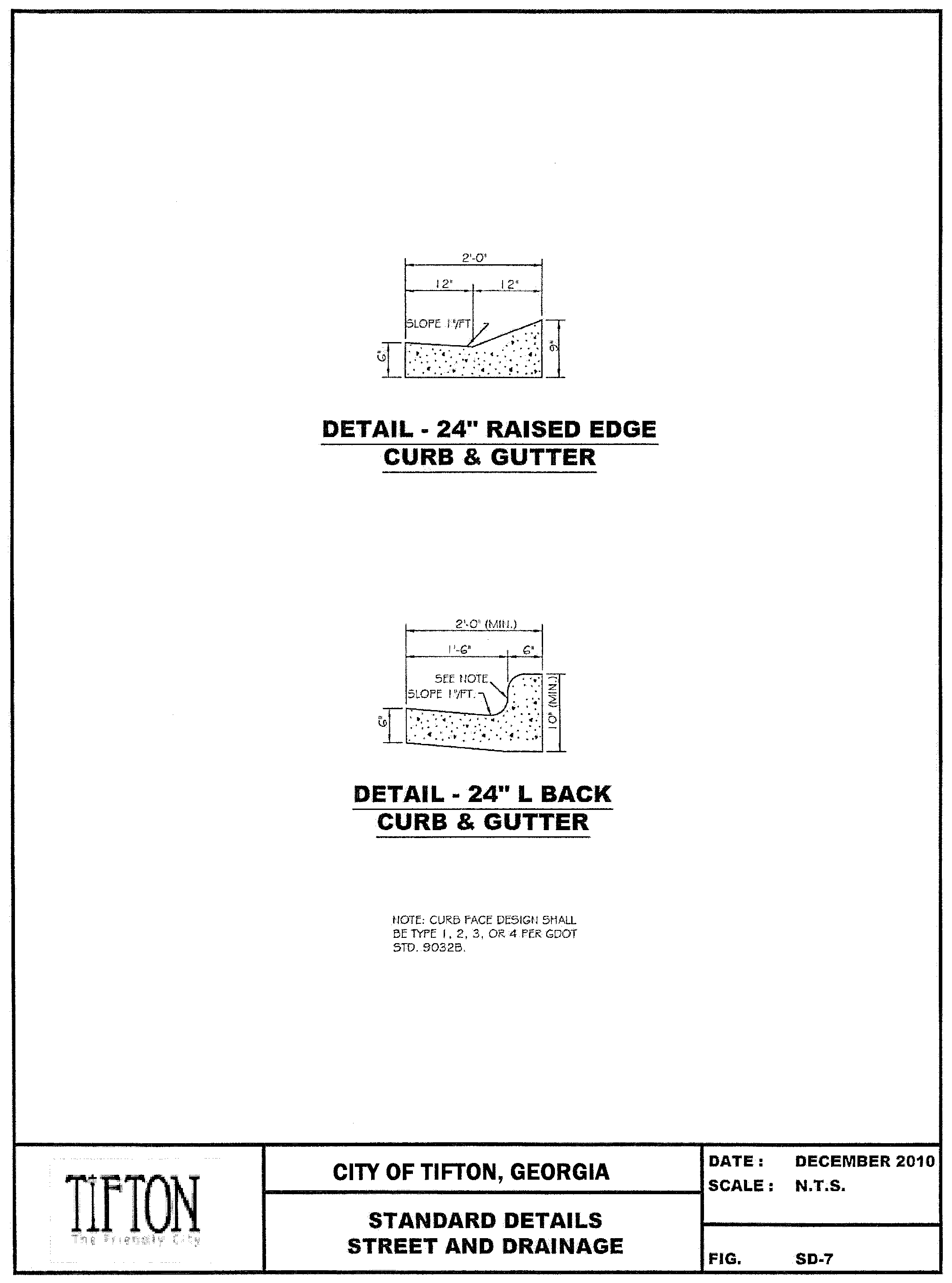
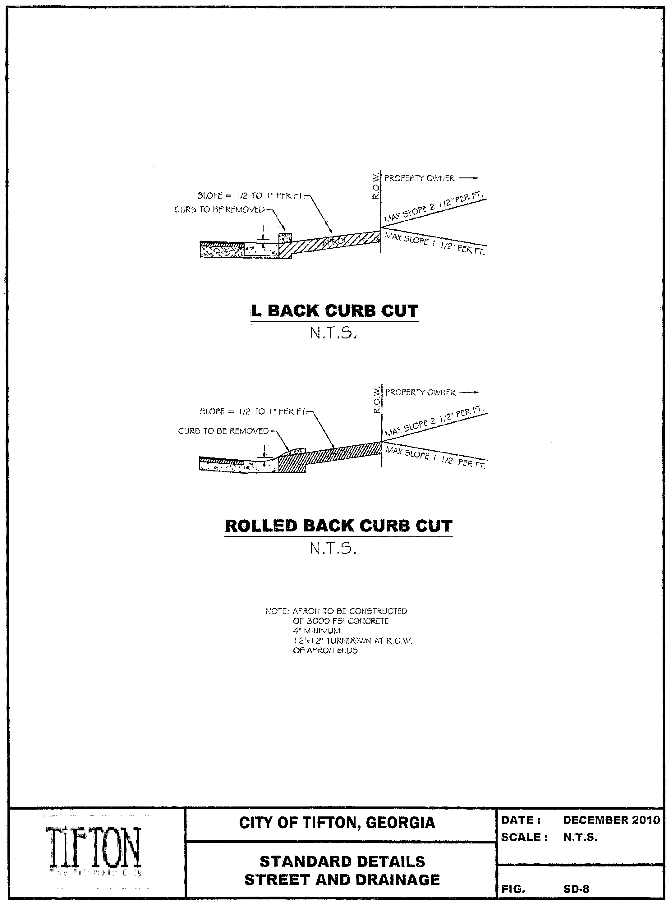
5.7 Curb and gutter.
Concrete curbs and gutters shall be constructed with Portland Cement Concrete having a twenty-eight (28) day breaking strength of three thousand (3,000) psi. Slip form or machine curb and gutter shall have expansion material minimum of one-half (1/2") inch thick with a maximum spacing of one hundred (100') feet and abut a solid structure where one (1) day's pour abuts a previous day's pour. Construction joins 1/4 - 1/3 the depth of the gutter shall be sawed or tooled at a maximum spacing of ten (10) linear feet. Concrete curb and gutter shall meet GDOT Standard 9032B, modified to eighteen inches (18") for commercial/parking lots and twenty-four inches (24") for all local and collector roadways designed with curb and gutter. When a standard curb is used, it shall be a minimum of six inches (6") (GDOT Std. 9032B Type 2 curb) in height. Curb cuts shall also be in accordance with GDOT Std. 9032B, Details of Recessed Curb. Typical details for curb and gutter, as well as curb cuts, are illustrated in the attached detail drawings. For major arterial roadways, the design must meet all applicable GDOT standards. Design and spacing requirements for curb and gutter are included in section 6.7.1.
5.8 Sight distance and alignment.
All driveways shall be located and streets aligned so as to provide at least the horizontal and vertical sight distances as listed below. All sight distances shall be determined by the methods found in the latest edition of A Policy on Geometric Design of Highways and Streets (AASHTO).
5.8.1 Horizontal Site Distance. Horizontal sight distance refers to the ability to detect objects in the roadway while negotiating a horizontal curve. The distance is measured from a point at which the height of the driver's eye is 3.50 feet above the roadway to a stationary object having a height of six (6) inches above the roadway.
Table 5.8.a. Minimum Horizontal Site Distance
5.8.2 Vertical Site Distance. Vertical site distance refers to the ability to detect an object in the roadway while negotiating the crest of a hill. The distance is measured the same as for horizontal curves.
Table 5.8.b. Minimum Vertical Site Distance
5.8.3 Minimum Horizontal Radii of Centerline Curvature.
Table 5.8.c. Minimum Horizontal Radii
5.8.4 Tangents. Between reverse curves there shall be not less than the following minimum tangents.
Table 5.8.d. Minimum Tangents
5.8.5 Super Elevation. The design of arterial and collector roadways may require the super-elevation of the travel surface on horizontal curves, as determined by design speed, in accordance with AASHTO Standards. The design and horizontal alignment for local streets serving residential areas should avoid the use of super-elevation where possible, as required by design speed. In all instances, the maximum super-elevation rates shall be in accordance with AASHTO and GDOT Standards. Under no circumstance is a curved street of any classification to be reverse super-elevated.
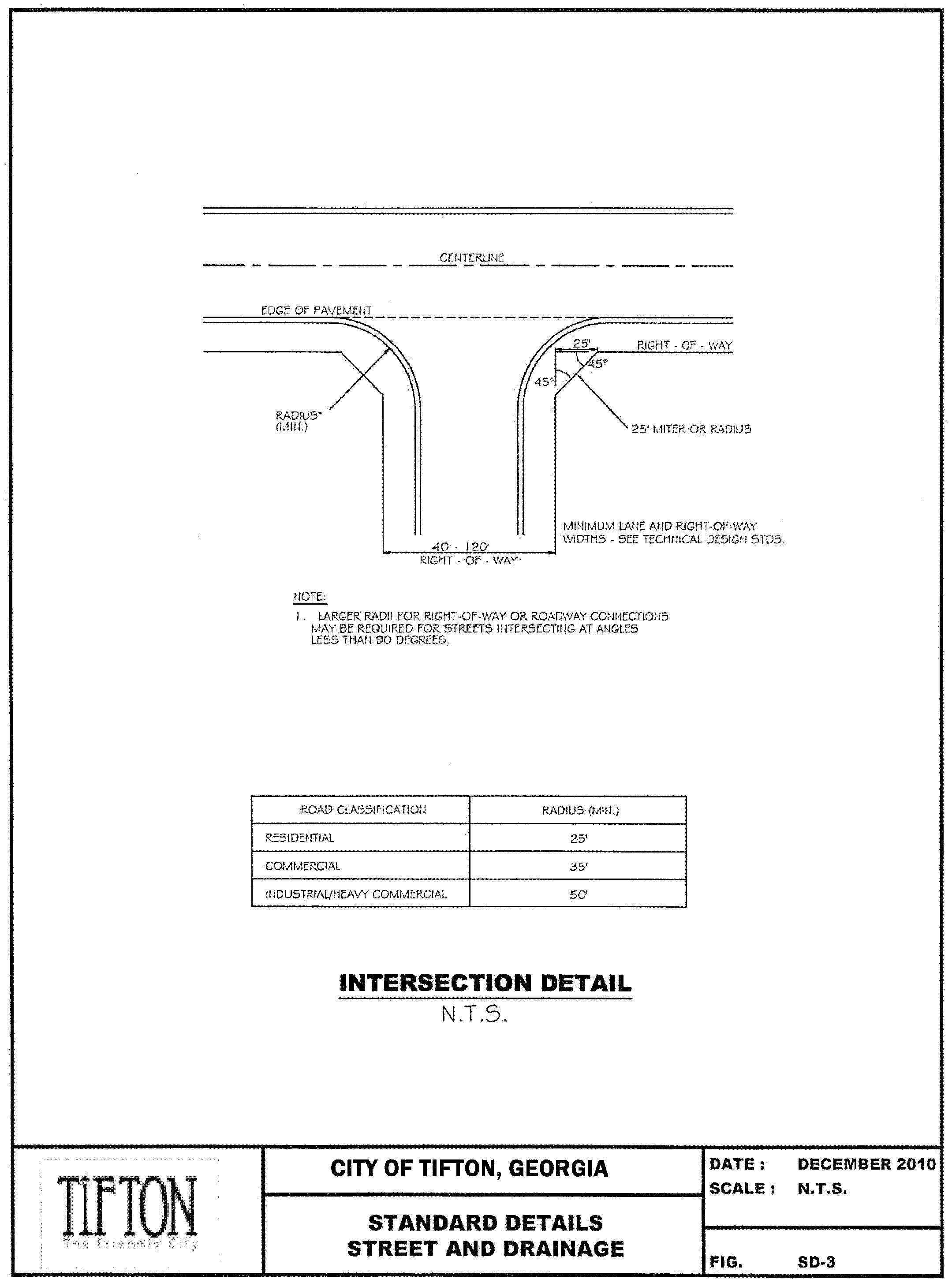
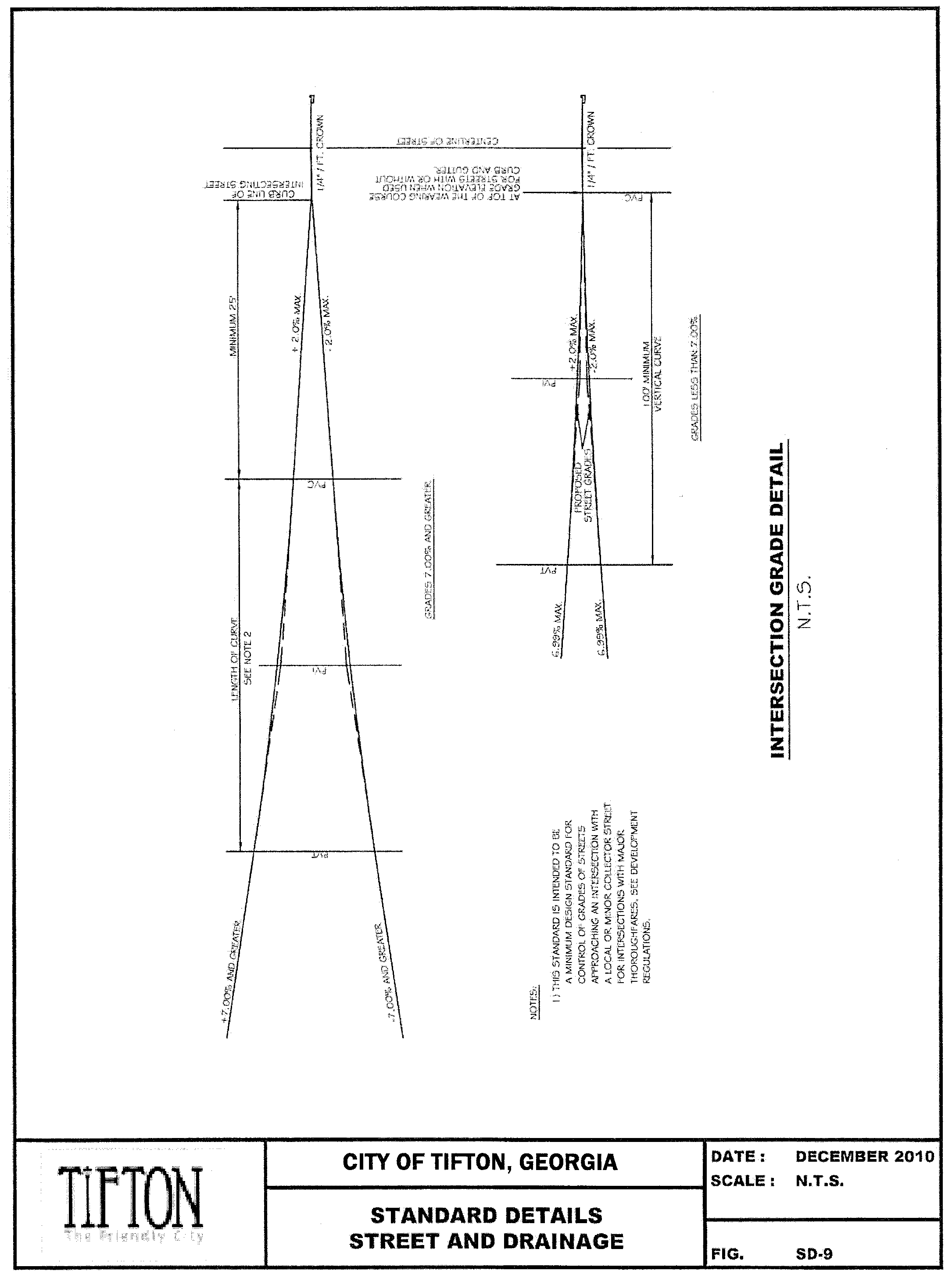
5.8.6 Intersections. In approaches to intersections, there shall be a leveling of the street at a grade not exceeding two (2) percent for a distance of not less than fifty (50) feet from the nearest right-of-way of the intersecting street (refer to typical details).
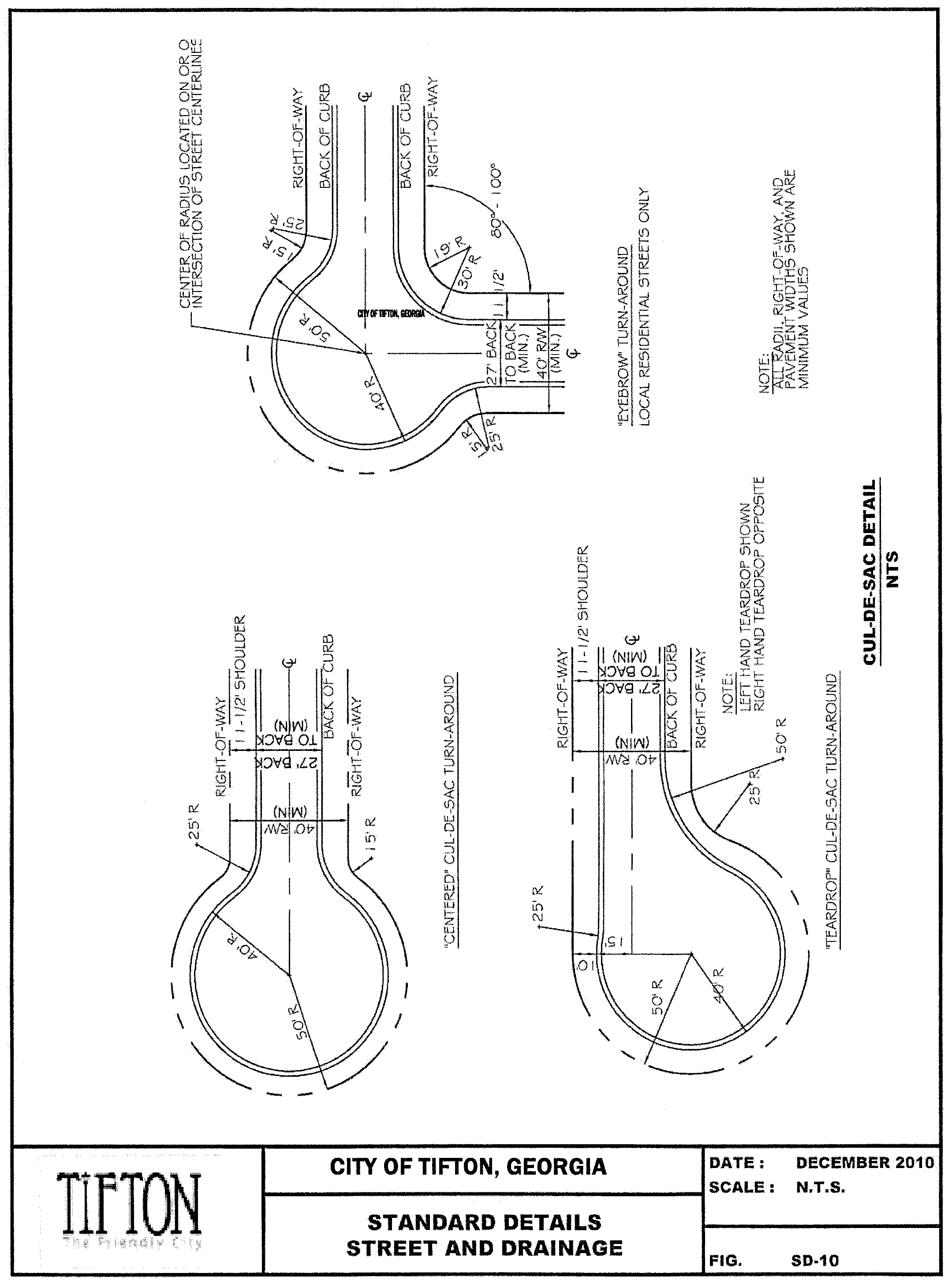
5.9 Minimum cul-de-sac specifications.
A.
Permanent cul-de-sacs shall be limited in length so that each cul-de-sac serves as street access for no more than twenty-five (25) lots.
B.
Cul-de-sacs shall terminate in a circular turnaround having a right-of-way of not less than 100 feet.
C.
Paving within the turnaround shall have an outside diameter of not less than eighty (80) feet.
D.
Islands are prohibited in cul-de-sacs.
E.
For typical cul-de-sac layout, refer to attached details.
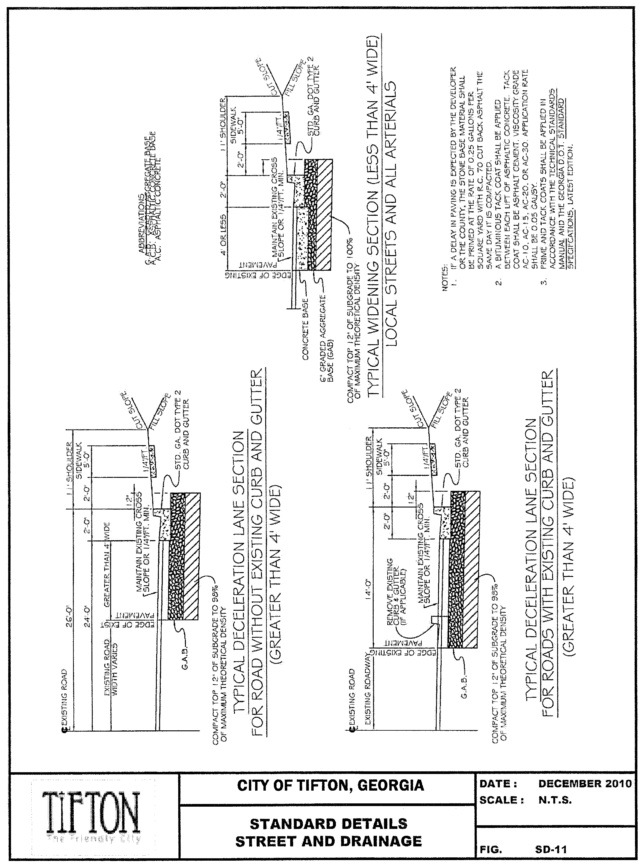
5.10 Acceleration and deceleration lanes.
Table 5.10.a. Minimum Deceleration Lane Design
For any driveway or street located on a major thoroughfare, except driveways serving one (1) to five (5) single-family residences, a deceleration lane shall be provided. The minimum length for deceleration lanes at all new street locations shall be as shown above except that either the SDRC or the GDOT district traffic and safety engineer, as applicable, may specify longer or shorter deceleration lanes based on grade, distance from an intersection, design speed, etc.
The Georgia DOT will determine the need for and design of acceleration lanes on state routes.
The SDRC shall determine the need for and design specifications for acceleration lanes along county streets.
Typical sections for the addition of deceleration and widening sections are included in the attached typical detail drawings.
5.11 Turn lanes.
Turn lanes, left and right, shall be designed in accordance with the Manual for Uniform Traffic Control Devices (MUTCD). The developer/contractor shall be responsible for the installation of turn lanes and intersection improvements where a new roadway meets an existing paved roadway within the County. The developer/contractor shall resurface all lanes within the improvement area when turn lanes are required.
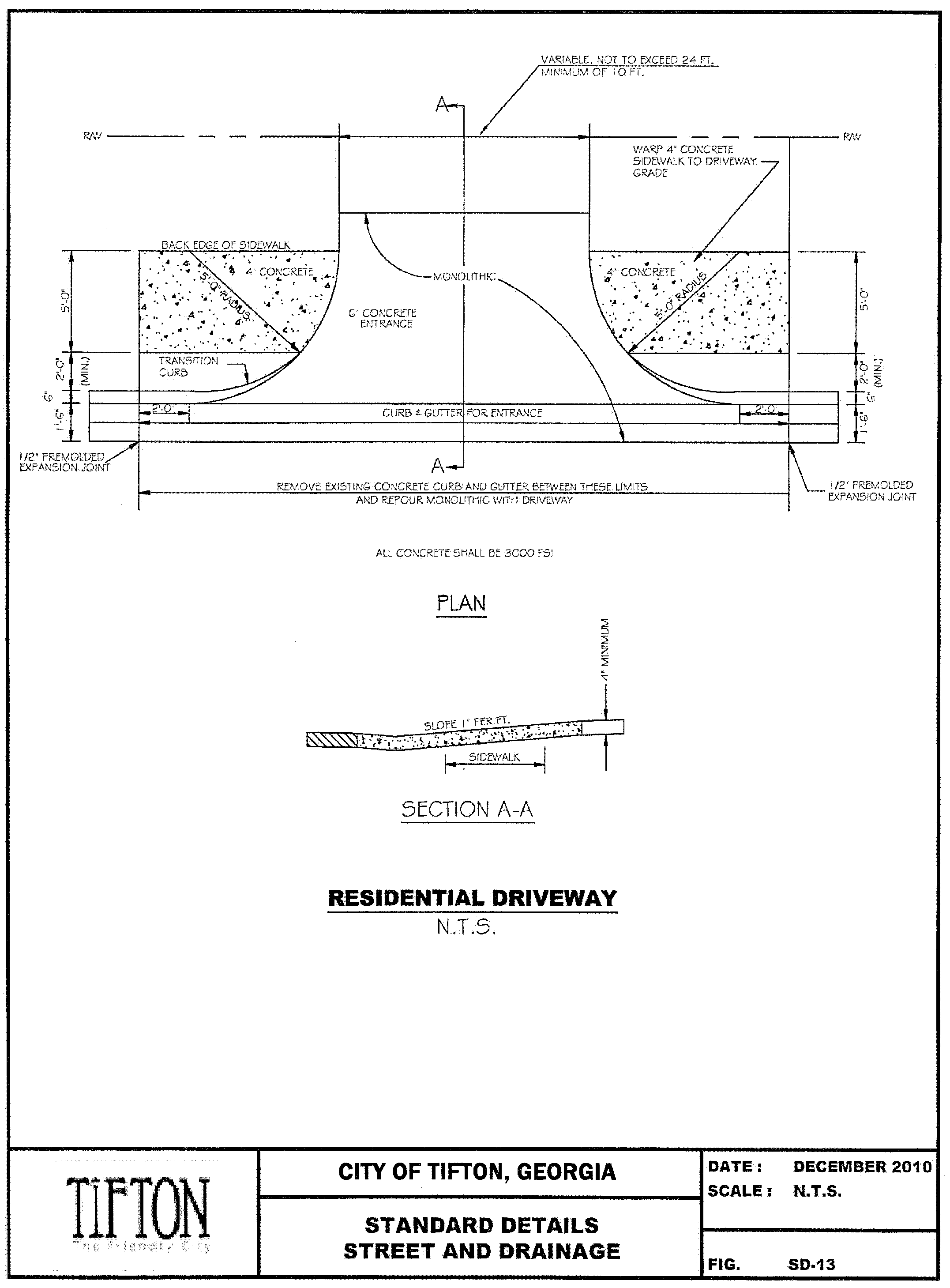
5.12 Driveways.
5.12.1 Driveway Dimensions. Residential driveways shall have a maximum width of twenty-four (24) feet measured at the right-of-way line from back of curb to back of curb (or edge of pavement if there is no curb).
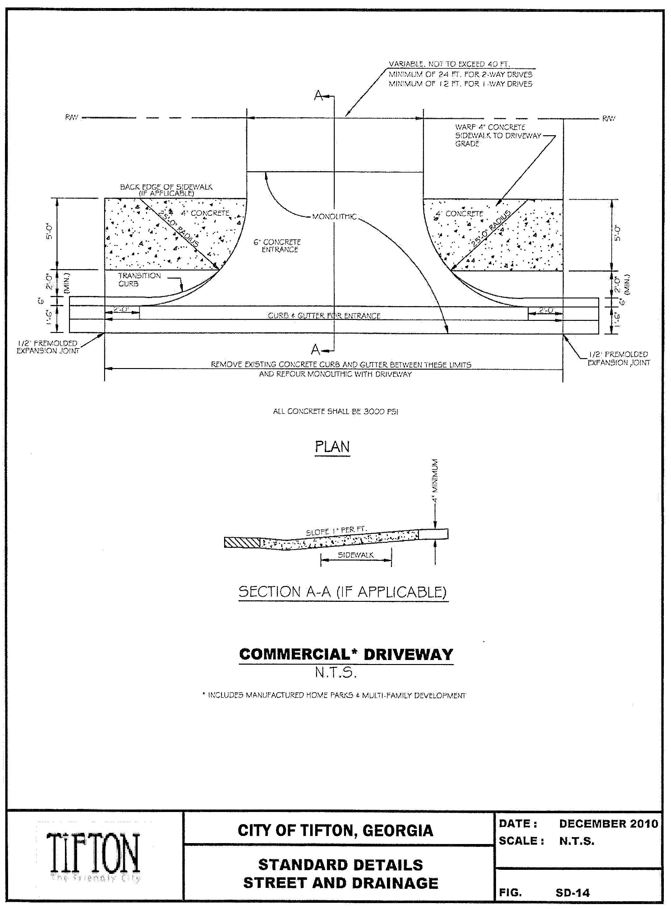
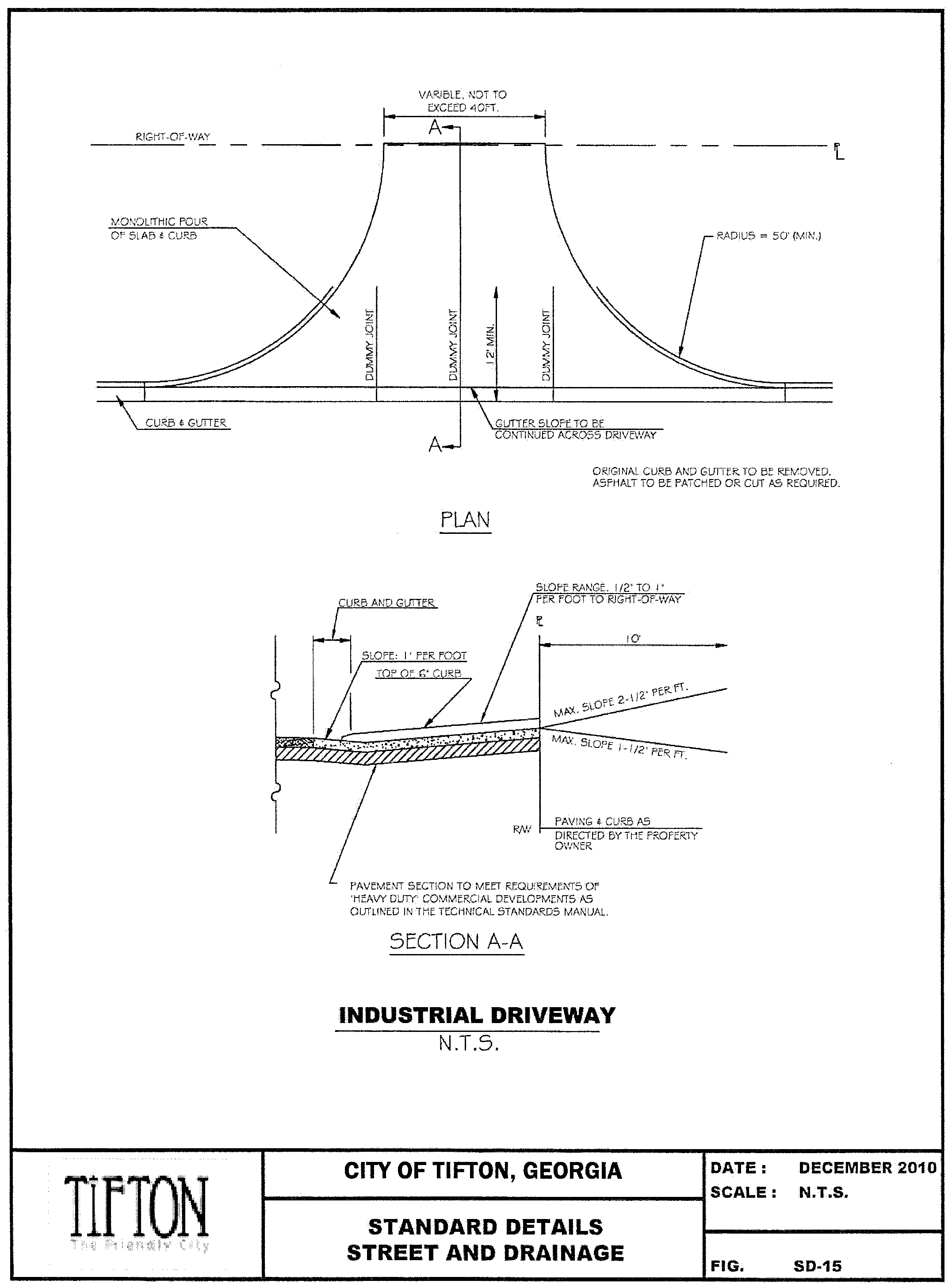
Commercial, industrial, manufactured home park and multi-family development driveways shall have a maximum width of forty (40) feet measured at the right- of-way line (back of curb to back of curb or from edge of pavement if there is no curb). For those businesses with frequent or heavy freight traffic, the SDRC will approve driveway widths and radii in excess of forty feet on a case by case basis.
Two way drives will be a minimum of twenty-four feet in width measured at the right-of-way line from back of curb to back of curb.
5.12.2 Typical Driveway Details. For typical driveway details, refer to the attached typical details.
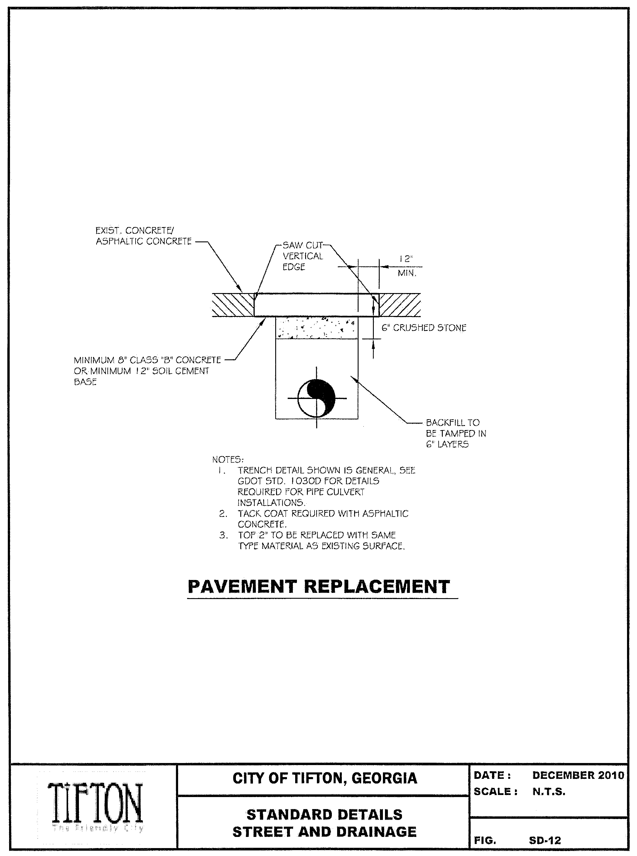
5.13 Street resurfacing (if required).
A.
All work shall be in conformance with the Georgia Department of Transportation Standard Specifications for Construction of Roads and Bridges, latest edition.
B.
All weak areas shall be removed and repaired with proper full depth patches. All debris (soil, GAB, and asphalt) shall be removed and disposed of properly.
C.
The surface to be overlaid shall be thoroughly cleaned and all debris removed.
D.
A track coat of asphalt (AC-10 or AC-20) shall be applied to the entire surface to be overlaid.
E.
The overlay thickness shall be 1 - 1 ½" inches of 9.5 mm SuperPave asphalt concrete. For lifts of 1 ½" inches or greater, 12.5 mm SuperPave asphalt concrete shall be used. The maximum lift thickness shall be 2" inches.
F.
Prior to placing the overlay, a leveling course of 4.75 mm SuperPave asphalt concrete shall be used where necessary or as determined by the SDRC or Road Department.
G.
The County will evaluate the existing pavement conditions and determine the overlay thickness using the methods in the Asphalt Institute's manual, Asphalt Overlays for Highway and Street Rehabilitation. For all streets other than residential, actual traffic counts will be obtained and coring, or other acceptable methods of obtaining the actual existing pavement thickness, will be utilized. In no case shall an overlay thickness be less than one (1) inch.
H.
For typical street resurfacing and replacement and saw cuts, refer to the attached typical details.
5.14 Street and traffic signs.
Developers shall be responsible for placing street signs and traffic signs in accordance with these regulations. Signs and posts shall be installed in accordance with the Manual for Uniform Traffic Control Devices (MUTCD) and must meet clearance, height above pavement, and all other applicable regulations. All required signs shall be in place prior to the occupancy of any structure and must be inspected and approved by the SDRC prior to the acceptance of a roadway by the County.
Sign posts shall be square tube with break-away support. Signs shall be Telespar (or approved equal) and meet the following criteria:
• Square posts
• 7/16" pre-punched holes on 1" centers
• 14 Gauge
• Steel with Pre-galv Plus coating
• Corner bolted
• Anchor a minimum of 36" 12-gauge tubing (1" - 2" left exposed above the surface)
• Shall have the following dimensions (or as approved by SDRC):
Table 4.14.a. Street Post Dimensions
5.14.1 Street Name Signs. Major street name signs shall be installed above the intersecting local street name sign. All street name signs shall be mounted parallel or nearly parallel to the street and shall be visible on both sides. A street name sign shall be installed for every street at an intersection.
Standard street name signs shall be extruded nine (9) inch blanks with six (6) inch letters. County road signs shall be white on green, and private road signs shall be white on blue.
5.14.2 Traffic Signs. Traffic control devices to include signs, signals, street markings, etc., shall be installed by the developer. The type and location of traffic control devices shall be determined by the SDRC's Engineer based upon the latest edition of the Manual on Uniform Traffic Control Devices (MUTCD), latest edition.
Stop signs shall be installed at every intersection. Stop signs shall be 30-inch unless at an intersection of 45 mph road or greater. In this case, a 36-inch stop sign is required. Speed limit signs shall be 24-inch by 30-inch. All other signs shall be in accordance with the MUTCD.
5.15 Striping and pavement marking.
The contractor shall be responsible for the installation of pavement markings to include, at a minimum, centerline striping, edge of pavement striping, stop bars, raised pavement markers (turtles), words, directional arrows and chevrons (hatches). Additional pavement markings may be required at the SDRC Engineer's discretion. All pavement markings except centerline striping and edge of pavement striping shall be thermoplastic. Stop bars shall be a minimum of twenty-four (24) inches, and words, chevrons, and directional arrow dimensions shall be in accordance with GDOT Standards (see GDOT details t01 through t19).
5.16 Utility locations.
In order to promote uniformity in installation and more effective and less damaging maintenance, a uniform system for locating utilities is hereby established. The locations are noted in the typical details. Applicable utilities and their locations shall be noted on subdivision construction plans and as-built drawings.
Detection tape for utilities may be required at the discretion of the SDRC. Detection tape shall be composed of a solid aluminum foil encased in a protective plastic jacket. Tapes shall be color coded in accordance with APWA color codes with the following legends: Water Systems, Safety Precaution Blue, "Caution: Water Line Buried Below". Colors may be solid or striped. Tape shall be permanently printed with no surface printing allowed. Tape width shall be minimum 2-inches when buried less than 10-inches below the surface. Tape width shall be minimum 3-inches when buried greater than 10-inches and less than 20-inches. Detection tape shall be equal to Lineguard Type III Detectable or Allen Systems Detectatape Wire. In addition, prior to backfill of trench the Contractor shall furnish and install 14 gauge coated copper wire. The wire shall be installed along the pipe during the backfill operation. Wire shall be brought up at each hydrant.
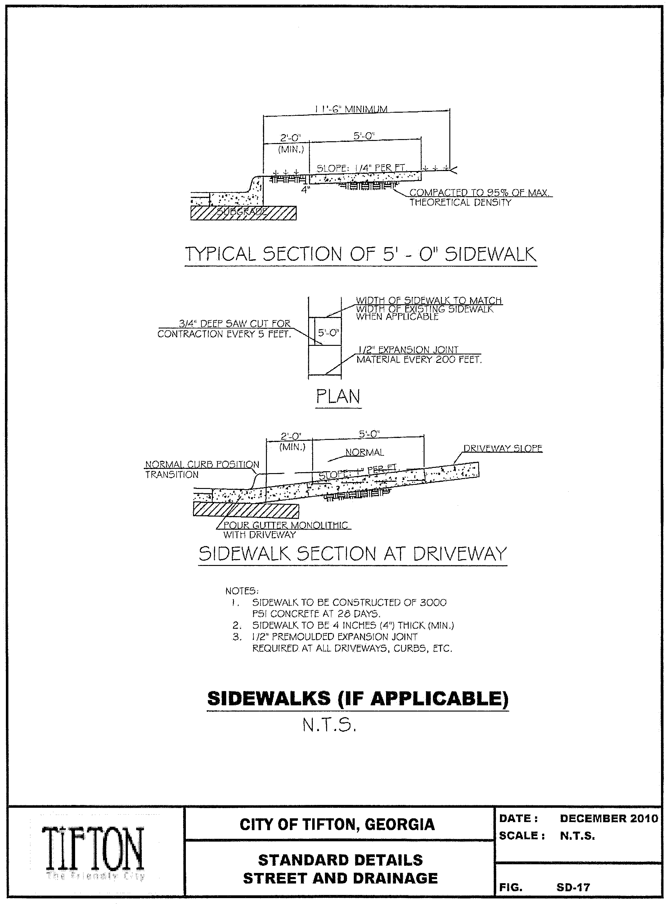
5.17 Sidewalks (if applicable).
A.
Sidewalks are required for all developments on parcels which connect to an existing sidewalk system (a neighboring parcel has a pre-existing sidewalk). In this case, the sidewalk will be carried across/through the development, aligning to the existing sidewalk system.
B.
Sidewalks shall be five (5) feet wide and shall be designed in accordance to all applicable American Disabilities Act (ADA) standards.
[C].
Sidewalks shall be constructed only on individual lots that have been permitted for construction.
[D].
For typical sidewalk cross-sections, refer to the attached typical details.
5.18 Landscape islands/traffic dividers (if applicable).
In order to promote uniformity in the configuration and construction of landscape islands/traffic dividers ("islands/dividers") within the right-of-way at entrances to residential, commercial, industrial or institutional developments, a uniform standard is hereby established.
A.
Where an island/divider is planned, the right-of-way shall be a minimum eighty (80) feet in width at the connecting public road. The right-of-way shall remain eighty (80) feet in width for a distance of 150 feet at which point the right-of-way will taper to the appropriate right-of-way width as required in Section 5.3.
B.
The island/divider shall be delineated with curb and gutter regardless of whether curb and gutter is required in the remainder of the development.
C.
The island/divider shall be at least 100 feet long and shall not be more than sixteen (16) feet in width from the back of curb to back of curb with a sixteen (16) foot travel lane on each side of the island/divider.
D.
No signs or structures shall be allowed in the island/divider. No trees or plants shall be placed in the island/divider that will block a person's view of oncoming traffic travelling within the connecting roadway. Any object encroaching into the right-of- way or obstructing the view of oncoming traffic shall be removed.
Sec. 6. - Stormwater design standards and specifications.
6.1 General requirements.
An adequate drainage system, separate and independent of any sanitary sewer system and including any necessary ditches, pipes, culverts, intersectional drains, drop inlets, bridges, etc., shall be provided for the proper drainage of all surface water for all applicable land developments. Sizing and location of all drainage structures shall be the responsibility of a qualified Georgia registered design professional. The County shall require the use of on-site control methods such as retention or detention to mitigate the stormwater and drainage impacts of the proposed land developments. The SDRC shall not approve any preliminary plat of a subdivision that does not make adequate provisions for storm and flood water runoff channels or basins as determined by the SDRC's Engineer.
No building permit shall be issued for any building within a subdivision or no development permit shall be issued for the development of land, if an adequate system of drainage and stormwater management is not present throughout the land to be developed.
For development or redevelopment projects, on-site control methods, such as retention or detention, shall be provided for the ENTIRE site when,
A.
The amount of impervious surface is 5,000 square feet or more, regardless of whether the impervious surface is new or being replaced.
B.
When the land disturbance activity associated with the proposed development/redevelopment is 1 acre or more.
6.2 Method of design and capacity.
Storm sewers, where required, shall be designed in accordance with the Georgia Stormwater Management Manual (GSMM), latest edition, and the County Stormwater Design Standards as outlined below. Copies of all design computations shall be submitted along with required plans.
Drainage improvements shall consider and accommodate, as necessary, potential runoff from the entire upstream drainage area as well as from within the site. The drainage improvements shall be designed to prevent effects on the upstream drainage system and increases in runoff to downstream systems for each of the design storms to the extent practicable.
6.3 Runoff computation.
The designer should consult Table 2.1.1-2 in the GSMM when deciding which hydrologic method to utilize. The following general applications should be applied:
A.
For all drainage areas less than 25 acres, the Rational Method shall be used.
B.
For all drainage areas greater than 25 acres, the SCS method or similar Unit Hydrograph Method shall be used. Computer methods with routing capability may also be used.
6.4 Design frequency.
A.
The 100-year average return frequency storm shall be used for the design of all onsite storm water conveyance systems.
B.
The 100-year average return frequency storm shall be used for all offsite drainage which enters the site and/or is conveyed through the site by the storm system.
C.
Detention systems shall be designed to meet standards 3, 4 and 5 of the GSMM.
6.5 Rainfall estimation.
A.
For the Rational method, Georgia Soil Conservation rainfall intensities shall be used.
B.
For the SCS method, the 24-hour rainfall depths as shown in the TR-55 Manual shall be used.
6.6 Runoff coefficients/Curve numbers.
A.
For the Rational method, standard runoff coefficients shall be used.
B.
For the SCS method, the curve numbers as shown in the TR-55 Manual shall be used.
6.7 Pre-development site conditions.
A.
For redevelopment sites, all existing impervious areas shall be treated as unimproved (i.e. forested) in the pre-development analysis.
For new development sites, existing conditions shall be defined as the conditions of the site at the time of application for a Land Disturbance Permit.
6.8 Inlet design.
6.8.1 Spread Limits.
A.
The maximum allowable spread in the roadway shall be based on the 2-year design storm and shall be limited to no more than six (6) feet of spread in the roadway gutter. Inlets shall be located along the roadway at sufficient intervals to intercept flows before they exceed the maximum spread limit. In no instance shall inlet spacing exceed three hundred (300) feet.
B.
The formulas for gutter flow shall be used to determine the spread in the roadway.
C.
At sag locations, the roadway shall have a minimum of 0.5% longitudinal slope within fifty (50) feet of the level point in the sag. For large flows, flanking inlets may be required on either side of the low point to prevent exceeding the spread limit.
6.8.2 Capture Efficiency.
A.
For the 10-year design storm, the capture efficiency for inlets on grade shall be no less than 90%, and the capture efficiency for inlets at sump locations shall be 100%.
B.
At sump locations, the capacity of the inlet shall be determined using the weir equation unless precast boxes with special inlets are used, which may be designed with the orifice equation. The minimum curb transition/apron length on either side of the basin shall be six (6) feet for inlets open on three (3) sides.
C.
Inlets shall not be allowed in the radius section at intersections, except where flows are very small, road grades are very flat, or the entire intersection is in a sag condition.
D.
Within a piped drainage system, an adequate number of manholes or inlets shall be constructed to provide for cleaning and maintenance of the stormwater system. In no instance shall spacing exceed three hundred (300) feet between structures.
6.8.3 Weir Opening Height. For inlets, the minimum allowable weir opening height shall be four (4) inches and the maximum allowable weir opening height shall be eight (8) inches. Trash racks shall be used as necessary or as required by the SDRC.
6.9 Pipe design.
A.
The Manning equation shall be used for pipe design, assuming pipe flowing full.
B.
The orifice equation shall be used to check the required headwater depths at all catch basins, junction boxes or pipe inlets along the system to predict and prevent surcharge conditions.
C.
Alternatively, a computer model using the Standard Step method or other approved energy-based method may be used to compute the hydraulic profile.
D.
For complex systems, the SDRC may require computation of the hydraulic profile.
E.
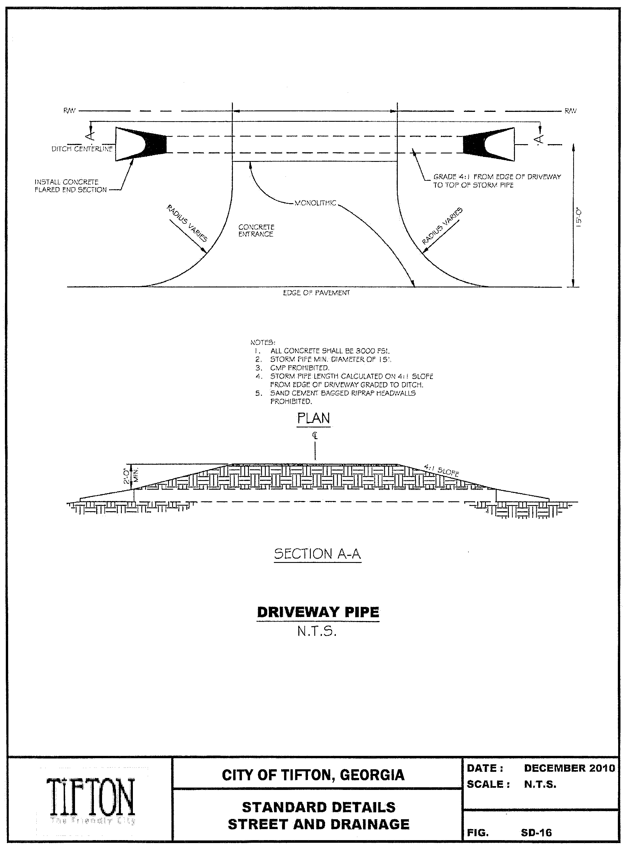
Minimum pipe size shall be 15" in diameter when using curb and gutter. A minimum of 18" diameter pipes are required for all ditch sections (i.e. driveway pipes), except for sock drain systems.
F.
The maximum slope for all drainage pipe shall be 10%. In cases where steep slopes are inevitable, the design professional should use concrete anchors or other factory recommended anchor systems. Details shall be provided on the construction plans.
G.
In the case, due to cover restrictions, dual pipes (double barrel) must be used, headwalls will be required. No more than two (2) pipes will be allowed at a crossing if a larger pipe or structure cannot be installed due to cover restrictions.
6.10 Detention ponds.
Detention ponds, either dry or with permanent pool, shall be designed in accordance with the GSMM to accommodate Minimum Standards 3, 4, and 5 of the GSMM, including Stream Channel Protection for the 1-year, 24-hr storm event, Overbank Flood Protection for the 2- through 25-year storm events and Extreme Flood Protection for the 100-year storm event. Ponds shall be designed to reduce the post-development peak flows of the 1- through 100-year storm events to the pre-development rates. An emergency spill way shall be provided to accommodate a storm event exceeding the 100-year storm.
Inlet pipes shall be placed so that the invert of the pipe is above the permanent pool elevation. Riprap, or other energy dissipation methods, should be utilized at the end of an outlet to prevent scouring and erosion.
Outlet structures shall be designed to prevent clogging in accordance with the GSMM.
An adequate maintenance access easement of twenty (20) feet must be provided around the entire perimeter of a detention pond. The access easement shall be sloped toward the pond with a slope no less than 1% and no greater than 5%.
The maximum depth of a pond shall be 10 feet.
(Ord. No. 2020-06, 6-15-2020)
6.11 Outfall structure design.
Rip-rap shall be installed around the top and sides of all outfall pipes. On steep slopes, the last joint of pipe on a plain end outlet shall be a full eight (8) foot joint. A precast headwall or an approved reinforced concrete headwall is required for all pipe outfalls thirty-six (36") inches and over. Where a drainage outfall is an substantial distance above the bottom of a stream or ditch into which it empties, a junction box with a rip- rapped stub will be required.
6.12 Energy dissipation.
A.
Energy dissipation measures shall be installed at all pipe outlets to prevent downstream channel erosion. Rip-rap aprons shall be designed in accordance with Georgia Stormwater Management Manual guidelines for Storm Drain Outlet Protection or other approved method.
B.
Precast manhole sections may be adapted for use as energy dissipaters at outfalls. The energy dissipater shall be designed so as not to adversely affect the hydraulic capacity of the system.
C.
Grouted rip-rap may be used in high velocity conditions or where safeguarding of the material is needed. The SDRC may require rip-rap to be grouted on steep slopes and/or high velocity conditions or when stabilization of the rip-rap is needed.
6.13 Roadway culvert design.
A.
Roadway culverts refer to structures installed under the roadway which convey flows from existing creeks, live streams, or drainage channels that originate upstream of the site and carry offsite flows through the site.
B.
The design of all roadway culverts shall comply with GDOT and FEMA guidelines.
C.
The following table shall be used for the design of all roadway culverts.
Table 6.12.a. Culvert Design
D.
The permanent impoundment of water on the upstream side of the culvert (i.e., dams) is not permitted.
6.14 Open channel design.
A.
Open channels refer to all overland diversions, existing and proposed, which convey storm flows through the site.
B.
Grassed channels - where steep slopes, highly erosive soils, or other conditions prevent the proper establishment of grass by seeding & mulching, sod or manufactured erosion control mats will be required. Where grassing is required, the work will not be accepted until grass is well established as determined by the SDRC.
C.
For all open channels, which cross or border on building lots, and where the 100- year flow exceeds 50 CFS, the 100-year flood line shall be computed and the lowest floor elevations shall be set at least two (2) feet above the flood elevation.
6.15 Pipe construction materials.
A.
Design Loading - At a minimum, all pipe materials shall be capable of supporting H-20 loading under minimum cover. All HDPE pipe shall also be of sufficient thickness to meet the design load requirements for the proposed cover height. Greater design loadings shall apply to industrial, commercial, or special situations as appropriate.
B.
Minimum Cover - Two (2) feet minimum cover shall be required for all pipe materials in the right-of-way, measured from the outside top of the pipe to the finished subgrade at the lowest point. Minimum cover requirements may be reduced based on class of pipe being utilized only if extenuating circumstances exist. In these cases, Class V RCP will be required.
C.
Bedding - Minimum bedding standards for High-Density Polyethylene (HDPE) pipe shall be such that stone bedding (i.e. No. 57 stone) shall be placed to half of the pipe diameter for all depths greater than four feet and/or in accordance with manufacturer's specifications, whichever is greater.
D.
Storm Drain - All storm drain pipes located under roadways that are accepted by the County for long-term maintenance, shall be constructed of reinforced concrete pipe (RCP - Class 3 or better) meeting Georgia Department of Transportation Standards. All longitudinal storm drain pipes shall be reinforced concrete pipe (RCP - Class 3 or better) or High-Density Polyethylene (HDPE). All pipes shall have a minimum diameter of 15 inches and must be designed and installed with adequate cover in accordance with manufacturer's specifications. In situations where the SDRC has reason to suspect that a pipe system may have not been installed properly, the SDRC may require at their discretion, video inspections of pipe systems to be provided at the Owner's expense prior to acceptance of the system.
E.
Side Drains - All side drain pipes (driveway pipes) located within the public right-of- way or dedicated County easements that are accepted by the County for long-term maintenance, shall be constructed of HDPE or reinforced concrete pipe (RCP - Class 3 or better) meeting Georgia Department of Transportation Standards. The minimum diameter of all pipes shall be 18 inches and shall meet the standards set forth in section 6.15.C above.
F.
All other pipe systems not within the public right-of-way shall be constructed of reinforced concrete pipe (RCP - Class 3 or better) or HDPE meeting Georgia Department of Transportation Standards. In the case where HDPE pipe originating from private property is joined to RCP, in the right-of-way, a transition structure, approved by the SDRC, must be provided at the right-of-way line by the Owner.
All pipes must have a minimum diameter of 15 inches and must be designed and installed with adequate cover in accordance with manufacturer's specifications. The minimum cover for pipes, which run along individual lot property lines in residential developments, shall be increased to three feet to account for the potential for damage due to residential fence construction.
In situations where the SDRC has reason to suspect that a pipe system may have not been installed properly, the SDRC may require at their discretion, video inspections of pipe systems to be provided at the Owner's expense prior to acceptance of the system.
6.16 Inlets and manhole construction.
A.
Inlets and manholes shall be constructed in accordance with GDOT Standard Specifications.
B.
All structures deeper than four (4) feet must be constructed with steps.
C.
The minimum drop from the edge of the roadway to the throat of the inlet shall be six (6) inches for the standard two foot (2') offset from the road. Greater offsets shall require greater drops to achieve the desired 25% cross-slope for the apron.
6.17 Subsurface drainage (if applicable).
Subdrains may be required at the SDRC's discretion depending on roadway and groundwater conditions on site.
A.
Subdrains shall be constructed in accordance with the manufacturer's recommendations.
B.
Subdrains shall be installed within 2 1/2' of the back of the curb and shall be properly connected to a permanent drainage structure such as a catch basin, or routed to a suitable location off the right-of-way.
C.
All subdrains shall have a minimum of two (2) feet of cover.
D.
Subdrains shall be installed prior to the base course.
E.
Subdrains are required on both sides of the street where mucking out and backfilling have been done, or where the water table is within two (2) feet of the road centerline elevation.
F.
Subdrains must be inspected and approved during installation.
6.18 Miscellaneous drainage requirements.
A.
The required roadway and developed land drainage shall be directed to a drainage channel within the immediate drainage basin provided the receiving channel has existing sufficient capacity or is improved to provide sufficient capacity for conveyance of the outfall flows. Under extenuating circumstances where this is not feasible, the design engineer shall document a good faith effort of the attempts made to provide the required information to the SDRC in compliance with the above provisions.
B.
Damming Structures - No dams or structures serving as dams to impound water, or any portion of such a structure shall be allowed in the right-of-way. This further means that no County road shall pass over such a structure without approval from the appropriate agencies.
C.
Drainage Outfall into a Pond or Lake - Where a drainage outfall discharges into a pond or lake, rip rap shall be placed under and around the end joint as needed and on slopes at the end of the pipe. The outfall invert elevation must be above the normal pool elevation of the lake.
D.
Drainage Outfall into a Stream or Ditch - Where a drainage outlet is a substantial distance above the bottom of a stream or ditch into which it empties, a drop structure (junction box) with a stub or other approved outfall design must be used. In all other instances, the outfall will be required to have rip rap placed under and around the end joint as needed and on slopes at the end of the pipe. All discharge pipes 36" and over shall have a precast headwall or site-built reinforced concrete or masonry headwall.
E.
Stabilization of Open Channels - All open channels used for conveyance of roadway drainage shall be properly stabilized to prevent erosion, and shall require rip rap at all direction changes exceeding 25 degrees or as directed by the SDRC.
F.
Drainage Easements - Drainage easements of the following widths shall be provided and dedicated for maintenance and public use:
Table 6.17.a. Drainage Easements
1.
For minor ditches with open channel flow, the required easement width shall be determined from the equivalent pipe size required to carry the flow and the easement width (listed above) corresponding to that calculated pipe size.
2.
For major ditches or channels, the easement width shall be centered on the ditch or channel and be equal to the maximum top width of the ditch plus twenty (20) feet.
6.19 Rip rap.
Stone shall be hard quarry, fieldstone or recycled concrete (see Section 6.20 below) which will withstand exposure to water and weathering. Stone shall vary in size from 6" minimum to 24" maximum, and the gradation shall be such that approximately 60% of the rip-rap is 10" in size. All rip-rap shall be hand placed or satisfactorily machine placed.
6.20 Crushed concrete.
Crushed, recycled concrete may be used in place of stone riprap. The concrete shall be clean and free of foreign materials, reinforcing wire and/or steel. Gradation and size shall meet the requirements of traditional riprap.
6.21 Location.
Drainage facilities shall be located in the road right-of-way where feasible, and shall be constructed in accordance with the GSMM and these standards and specifications. Catch basins shall be located at low points of streets. Where topography or other conditions are such as to make impractical the inclusion of drainage facilities within road rights-of-way, perpetual, unobstructed easements at least twenty (20) feet in width for drainage facilities shall be provided across property outside the road right-of-way and with satisfactory access to the road.
6.22 Discharge.
Drainage shall be designed so as to avoid concentration of storm drainage water from each lot or land development site to adjacent lots, land development sites, or vacant properties. Storm water shall not be discharged directly to streams, lakes, rivers, tidal waters or any other environmentally sensitive area. It shall be directed toward natural overland drainages. If water must be discharged to a stream, or other water body the water quality flowing into the stream must meet or exceed the water quality in the receiving waters. The water quantity flowing into the stream must be evaluated to ensure the stream channel can accommodate the increased flows and not disrupt or degrade the ecology of the water body.
It shall be County policy that an increase in the elevation of flooding on an adjacent property(s) shall be unacceptable. In situations where flood elevations on an adjacent property will be increased due to development and/or construction of a stormwater management system/facility, the required conveyance level of service may be increased by the SDRC to result in no impact to the adjacent property(s). This requirement may be waived at the SDRC's discretion if the adjacent property owner(s) provides a permanent drainage easement between the two property owners. The easement shall provide that the owner of the impacted property acknowledges that an increase in flood elevations will occur on their property as a result of the proposed development. Additionally, the easement shall include at a minimum a map showing the extent of the pre-development and post-development 100-year floodplains. The easement must be recorded with the County as an attachment to the affected property's land deed and shall be binding on all future property owners.
6.23 Grading and site drainage.
Lots or land development sites shall be laid out so as to provide positive drainage away from all buildings, and drainage for individual lots or land development sites shall be coordinated with the general storm drainage pattern for the area. Buildings and parking lots shall be appropriately drained to prevent damage to abutting properties or public streets. All disturbed or graded ground areas of a building site not used for buildings or open storage areas shall be appropriately stabilized and grassed or covered with plants or landscaping materials.
6.24 Stormwater management plan report.
All development projects must submit a stormwater management plan report outlining the hydrologic and hydraulic impacts of the site on the stormwater system. At a minimum, this report must include the following sections:
• Certification by a Qualified Registered Design Professional
• Project Narrative
• Existing Conditions Hydrologic Analysis
• Post-Development Hydrologic Analysis
• Stormwater Management System Design
• Downstream Analysis
• Erosion & Sedimentation Control Plan
• Planting Plan (if applicable)
• Operations & Maintenance Plan
The following subsections outline the requirements for each of the elements outlined above.
6.24.1 Professional Certification. Each report should begin with the following statement and be signed and sealed by the professional who prepared the report:
"I, (Name of Professional), a Registered (Professional Engineer / Land Surveyor/other qualified design professional) in the State of Georgia, hereby certify that the grading and drainage plans for the project known as (Project Name), lying in Land Lot (_____), of the (_____) District, located at (address), City of Tifton, Georgia, and identified on tax map (_______) as parcel (_____), have been prepared under my supervision, and, state that in my opinion, the construction of said project will not produce storm drainage conditions that will cause damage or adversely affect the surrounding properties. This (Day) day of (Month), (Year)."
6.24.2 Project Narrative. A brief narrative should be provided with the report outlining the project.
6.24.3 Existing Conditions Hydrologic Analysis. The existing conditions hydrologic analysis should provide the reviewer with a comprehensive evaluation of the site conditions prior to development of the project.
The designer should provide the following information with the Existing Conditions Hydrologic Analysis element of the report:
A.
Existing Conditions Narrative
• A written description of the existing conditions found at the site
• Analysis of runoff provided by off-site areas upstream of the project site
• Methodologies, assumptions, site parameters and supporting design calculations used in analyzing the existing conditions site hydrology.
B.
Existing Conditions Map
An existing conditions map should be provided with the report including but not limited to the following:
• Topography (2-ft. or less contour interval) of existing site conditions.
• Perennial/intermittent streams, wetlands, lakes and other surface water and water resources features.
• Natural Resources Inventory and Site Fingerprinting data per the procedures outlined in Section 1.0 of the Green Growth Guidelines (as necessary).
• Drainage basin and sub-basin delineations.
• Drainage basin and sub-basin delineations for each contributing drainage area upstream of the project site on an appropriate map.
• Existing stormwater conveyances and structural control facilities.
• Direction of flow and discharge points from the site including sheet flow areas.
• Any area of significant depression storage.
• Federal, State and local buffers and conservation areas.
The map should provide a clear understanding of the drainage patterns present throughout the site as well as drainage onto the site from upstream/adjacent areas.
C.
Existing Conditions Information
Pertinent information should be included in the report in table format that will enable the reviewer to understand how various parameters were applied in existing conditions analysis. Additionally, tables should be included documenting the results of the modeling.
• A table listing the acreage, soil types and land cover characteristics for each sub-basin.
• A table listing the total acreage, composite curve number and time of concentration for each sub-basin.
• A table listing the peak runoff rates and total runoff volumes from each sub-basin.
• A table listing the peak runoff rates and total runoff volumes for each drainage area upstream of the project site.
• A table listing the peak runoff rates and maximum water surface elevations for all detention facilities studied as part of the existing conditions analysis.
D.
Existing Conditions Model Diagram
A diagram of the hydrologic model for the existing site should be provided with the report showing each flow node.
6.24.4 Post-Development Hydrologic Analysis. The proposed conditions hydrologic analysis should provide the reviewer with a comprehensive evaluation of the site conditions following development of the project. The designer should provide the following information with this element of the report:
A.
Proposed Conditions Narrative
A written description of the proposed site conditions after construction should be provided. The narrative should describe the pertinent information and assumptions as to how the proposed conditions were analyzed by the designer.
B.
Proposed Conditions Map
A proposed conditions map should be provided with the report including but not limited to following:
• Topography (2-ft or less contour interval) of proposed site conditions.
• Perennial/intermittent streams, wetlands, lakes and other surface water features.
• Drainage basin delineations showing the location of each drainage sub- basin.
• Proposed stormwater conveyances and structural control facilities.
• Direction of flow and discharge points from the site including sheet flow areas.
• Location and boundaries of proposed natural resources feature protection areas.
• The map should provide an overview of the various drainage patterns proposed for the site as well as drainage onto the site from upstream areas.
C.
Proposed Conditions Tables
Tables should be included in the report that will allow the reviewer to understand how the applicable parameters were developed and utilized in modeling the proposed conditions for the site. Additionally, tables should be included documenting the results of the modeling.
• A table listing the acreage, soil types and land cover characteristics for each sub-basin.
• A table listing the total acreage, composite curve number and time of concentration for each sub-basin.
• A table listing the peak runoff rates and total runoff volumes from each sub-basin.
• A table listing the peak runoff rates and total runoff volumes for each drainage area upstream of the project site.
• A table listing the peak runoff rates and maximum water surface elevations for all detention facilities studied as part of the proposed conditions analysis.
D.
Proposed Conditions Model Diagram
A diagram of the hydrologic model for the proposed site should be provided with the report showing each flow node.
6.25 Stormwater management system design.
The stormwater management system design should provide the reviewer with a comprehensive description of the proposed stormwater management system components on site. The designer should provide the following information in the report:
6.25.1 Stormwater Management System Map.
• The stormwater management system map should document the various components of the stormwater runoff system for the site.
• Location of all structural and non-structural stormwater controls
• Location of all existing stormwater controls to remain after development
• Location of all proposed stormwater controls
• Location of all proposed impoundment type controls (i.e. detention ponds, stormwater ponds, stormwater wetlands, etc.)
• Location of all natural resource areas that will be incorporated into the stormwater management plan for the site.
• Location of all conveyance structures
• All impoundment type controls should be labeled with the following information as a minimum: maximum water surface elevations; depth and storage volumes for the design storm(s); and depth of maximum water surface if the design storm event is exceeded (i.e. top of dam) as well as volume calculations.
• All inlets to conveyance structures should be labeled with the following information: maximum design water surface and maximum potential water surface elevations.
• All pipes should be labeled with the following: length, diameter, material of construction and slope.
• Map showing all contributing drainage areas/sub-basin delineations.
• Soils Map, NWI Map (if necessary), USGS Quad Map, FEMA Map.
• Geotechnical information from the Natural Resources Conservation Service (NRCS) for the site indicating soil types, seasonal high ground water, and percolation rates (if necessary).
6.25.2 Narratives. The following narrative information should be provided:
• Narrative describing that the proper structural stormwater controls have been selected for the site conditions.
• Design calculations and elevations for all existing and proposed stormwater conveyance elements including stormwater drains, pipes, culverts, catch basins, channels, swales, areas of overland flow, etc.
• Design calculations and elevations for all structural water quality controls to be utilized for water quality improvement.
• Design calculations showing that the design meets the applicable requirements as set forth herein.
• Type of storm routing software utilized for design (if applicable).
6.25.3 Downstream Analysis. The downstream analysis should provide the reader with a comprehensive picture of the downstream areas and their capacity to accommodate stormwater runoff from the proposed development.
• Maps
a.
Drainage basin delineations showing the point at which the contributing area of the project represents 10% of the total drainage basin area as defined in Section 2.1.9.2 of the Georgia Stormwater Management Manual (latest edition).
b.
Identify culverts, channels and other structural stormwater controls that the stormwater runoff from the site will eventually pass through prior to the 10% point as identified above.
• Narratives
a.
Provide a narrative with associated calculations to how the demonstrate was performed and to show that no adverse impacts will occur after construction of the proposed site.
6.25.4 Planting Plan. A planting plan should be included in the report for all water quality controls that utilize vegetation as a pollutant removal method.
6.25.5 Operations & Maintenance Plan. A narrative of what maintenance tasks will be required for the stormwater controls specified for the site as well as the responsible party(s). The designer should consult the Georgia Stormwater Management Manual (latest edition) for additional insight on this issue.