
Lady Lake City Zoning Code
CHAPTER 14
WATER, REUSE WATER AND SEWER STANDARD SPECIFICATIONS
Sec. 14-1.- Introduction.
The specifications set forth herein are meant to provide minimum standards for the construction of water and sewage transmission and collection facilities which meet the following conditions:
a)
Facilities to be constructed within the Town of Lady Lake rights-of-way.
b)
Facilities to be turned over to the Town of Lady Lake.
c)
Facilities to become a permanent part of the Town of Lady Lake utilities system.
These specifications are not meant to be totally restrictive in nature; that is, they do not depict the only acceptable method of design. Rather, their purpose is to describe minimum acceptable standards of construction and to promote uniformity where practical. It is felt that adherence to the standards presented in this booklet will benefit both the citizens of Town of Lady Lake and the operators of the facilities.
Should any design be submitted which varies significantly from the standards set herein or uses materials other than those recommended it should be accompanied by appropriate supporting documentation or engineering studies. Any variance must be approved by the Engineers and Commission.
Please note that all plans submitted for review must be in conformance with all federal, state, county, and Town regulations established by recognized private and governmental agencies, unless stated otherwise in these specifications.
Sec. 14-2. - Basic information.
a)
Authority.
1)
Approval. These design standards are accepted and approved by the Town Commission.
2)
Scope and intent. It is intended for these development procedures to establish minimum engineering requirements for projects submitted to the Town. The development procedures will apply to all development and construction projects, both public and private, within the jurisdiction of the Town of Lady Lake.
3)
Variances. Variances shall be allowed as specified in the Developmental Procedures and Regulations chapter.
4)
Penalties and enforcement.
A)
Any person who shall violate or fail to comply with any of the provisions of this chapter shall, upon conviction, be punished by a fine not to exceed five hundred dollars ($500.00) or six (6) months in jail or both. The Town Commission may enforce the provisions of this chapter by seeking injunctive relief or any other remedies provided by law.
B)
The Town shall have the authority to enforce the provisions of this chapter by the discontinuance of water service in the event of violation hereof. All water used in violation of a declaration of water shortage shall be billed at three times the regular rate.
5)
Changes to these standards. Changes to these standards may be made by Ordinance adopted by the Town Commission.
b)
General.
1)
100-year flood. The developer and his engineer are reminded that all water and sewer system components must be floodproofed against the 100-year flood occurrence and against inflow and infiltration, as required in the Building and Fire Codes chapter.
2)
Utility coordination. It shall be up to the developer to coordinate all utilities within his development.
3)
Notification. The Town shall be notified in writing of proposed date of the beginning of construction of the water and sanitary sewer facilities. Any time that work is to stop for a period of time in excess of two (2) working days, the Town shall be notified of such interruption.
4)
Power and authority of inspectors. Duly authorized employees of the Town bearing proper credentials and identification shall be permitted to enter upon all properties for the purpose of inspection, observation, measurement, sampling and testing in accordance with the provisions of this Code.
5)
Record drawings. Record drawings and other information, as required in Inspections and Acceptance section of the "Development Procedures and Regulations" chapter, shall be submitted at the completion of construction.
6)
Erosion control. Contractor is responsible for designing, providing, and maintaining effective erosion and sediment control during construction. The control measures must ensure that erosion and sedimentation will either be eliminated or maintained within acceptable limits as established by Lake County Environmental Services, Florida Department of Environmental Services, St. Johns River Water Management District, and applicable Town regulations. In the event such protection is inadequate, it will be the developer's responsibility to remove any downstream siltation prior to the time of final inspection.
7)
Warranties. The Town shall be provided five (5) year warranties on all pumps, motors, electrical panels, etc., by the contractor prior to final acceptance by the Town.
8)
Transfer of private ownership. When transfer of private facilities to public ownership takes place, all such private facilities shall be brought up to the current Town standards at no cost to the Town insofar as construction and maintenance are concerned, before the Town will accept such facilities. The Town is to be furnished copies of detailed cost breakdowns of project, all approvals, permits, certificates of completion, etc., to or from other agencies such as Lake County, Florida Department of Environmental Protection, St. Johns River Water Management District, Florida Department of Transportation, railroads, etc., before proceeding with construction. Proof of satisfactory completion of water and sewer facilities, positive water bacteriological tests, and submission of quick claim deeds, bills of sale, prior and current permits, warranties, manufacturers manuals, and a ten (10) percent two (2) year maintenance bond, and evidence of release of liens from contractors and subcontractors shall be furnished to the Town prior to acceptance.
9)
Property ownership. All facilities to be owned or maintained by the Town shall be located on Town property, within Town's right-of-way or on easements dedicated to the Town for the uses intended
10)
Trade names. Wherever a product is called for by name "or equal" shall be assumed to be included. The inclusion or use of a trade name is simply for information and is not an endorsement of the product.
11)
Drawing water from fire hydrants. A permit shall be required from the Department before water is drawn from any fire hydrant or other service outlet, except by the fire department in the regular discharge of its duties, and only after arrangements have been made for payment to the Town for water so drawn at a just and reasonable rate.
12)
Damaging equipment. It shall be illegal and subject to the punishment provided herein for any person to maliciously or willfully break, damage, destroy, uncover, deface or tamper with any structure, appurtenance or equipment which is a part of the Town water or sewerage systems.
c)
Discharge into Town Systems.
1)
No person shall discharge or cause to be discharged any stormwater, surface water, groundwater, roof runoff, subsurface drainage or industrial processed waters into the Town sewerage collection and treatment system.
2)
No person shall discharge or cause to be discharged any of the following described waters or waste into the Town sewerage system:
A)
Any liquid or vapor having a temperature higher than one hundred fifty (150°) degrees F.
B)
Any water or waste which may contain more than one hundred parts per million, or mg/l, of fat, oil, grease or wastewater required by ordinance to be treated with a pollutant interceptor or grease trap.
C)
Any gasoline, benzene, naphtha, fuel oil, or other flammable or explosive liquid, solid or gas.
D)
Any garbage that has not been properly shredded.
E)
Any ashes, cinders, sand, mud, straw, shavings, metal, glass, rags, feathers, tar, plastics, wood, or any other solid or viscous substance capable of causing obstruction to the flow in sewers or other interference with the proper operation of the sewerage works.
F)
Any waters or wastes have a pH lower than 6.2 or higher than 8.0, or having any other corrosive property capable of causing damage or hazard to structures, equipment, and personnel of the sewerage works.
G)
Any waters or wastes containing a toxic or poisonous substance in sufficient quantity to injure or interfere with any sewage treatment process, constitute a hazard to humans or animals, or create any hazard in the receiving waters of the sewage treatment plant.
H)
Any noxious or malodorous gas or substance capable of creating a public nuisance.
d)
Water Shortage Conditions. This section shall be enforced from time to time by the Town Commission at any regular or specially called public meeting declaring that a water shortage condition exists in the Town and shall be enforced until such time as the Town Commission at a regular or specially called meeting declares that the state of shortage no longer exist.
1)
Application of regulations. The provisions of this section shall apply to all persons using water in the service territory, regardless of whether any person using water shall have a contract for water services within the service territory.
2)
Certain uses prohibited. Between the hours to be designated by the Town Commission in its declaration that a state of water shortage exists, the use and withdrawal of water by any person for the following purposes is hereby prohibited:
A)
Watering yards. The sprinkling, watering or irrigating of shrubbery, trees, lawns, grass, ground cover, plants, vines, gardens, vegetables, flower, or any other vegetation.
B)
Washing mobile equipment. The washing of automobiles, trucks, trailers, trailer-houses, or any other type of mobile equipment.
C)
Cleaning outdoor surfaces. The washing of sidewalks, driveways, filling station aprons, porches, and other outdoor surfaces.
D)
Swimming pools. Swimming and wading pools not employing a filter and recirculating system.
E)
Escape through defective plumbing. The escape of water through defective plumbing, which shall mean the knowing permission for defective plumbing to remain out of repair.
3)
Exceptions. The Town Manager shall have the authority to permit a reasonable use of water in any case necessary to maintain adequate health and sanitation standards. Any user of water may apply for a temporary permit from the Department for relief from the provisions of this section provided a written request for authorization to use water shall indicate that a hardship exists and the nature of the hardship.
Sec. 14-3. - Utility excavation, trenching, and backfilling.
a)
General. The provisions set forth in this Section shall be applicable to all underground sewer and water piping installations, regardless of location, unless prior approval is received from the Town for special design considerations.
b)
Materials.
1)
Wood sheeting. Wood sheeting to be left in place shall be pressure treated with preservative in accordance with the current requirements of the American Wood Preservers Association Manual of Recommended Practice. The creosote oil used shall conform to the requirements of the State of Florida Department of Transportation, Standard Specifications for Road and Bridge Construction, when tested in accordance with AASHTO T60.
2)
Steel sheeting. Steel sheeting to be left in place shall be as specified in ASTM Designation A328.
3)
Concrete. Required concrete for anchors, thrust blocks, encasements or protective slabs shall have a minimum two thousand five hundred (2,500) pounds per square inch compressive strength.
c)
Workmanship.
1)
Trench dimensions and trench grade.
A)
Trench dimensions. Trench dimensions shall be according to OSHA regulations.
B)
Trench grade. Standard trench grade shall be defined as the bottom surface of the utility to be constructed or placed within the trench. Trench grade for utilities in rock or other non-cushioning material shall be defined as six (6) inches below the outside of the bottom of the utility, which six (6) inches shall be backfilled with extra utility bedding material. Excavation below trench grade that is done in error shall be backfilled to trench grade and compacted.
2)
Utility bedding.
A)
Class B (minimum utility bedding). The bottom of the trench shall be shaped to provide a firm bedding for the pipe. The pipe shall be firmly bedded in undisturbed soil, or hand shaped unyielding material. The bedding shall be shaped so that the pipe will be in continuous contact therewith for its full length.
B)
Class A (special utility bedding). Should special bedding be required due to depth of cover, impact loadings, or other conditions, Class A" bedding methods shall be installed consisting of sand or suitable crushed rock.
3)
Unsuitable material below trench grade. Soil unsuitable for a proper foundation encountered at or below trench grade, such as muck or other deleterious material, shall be removed for the full width of the trench and to the depth required to reach suitable foundation material, unless special design considerations received prior approval from the Town. Backfilling below trench grade shall be in compliance with the applicable provisions.
4)
Extra utility-bedding material. When rock or other non-cushioning material is encountered at trench grade, excavation shall be extended to six (6) inches below the outside of the bottom of the utility, and a cushion of sand or suitable crushed rock shall be provided.
5)
Sheeting and bracing. In order to prevent damage to property, injury to persons, erosion, cave-ins, or excessive trench widths, adequate sheeting and bracing shall be provided in accordance with standard practice and in accordance with all safety, protection of property, and other applicable laws and regulations, including OSHA and the Florida Statutes.
6)
Excavated material. Excavated material to be used for backfill shall be neatly deposited at the sides of the trenches where space is available, but far enough back from the trench to avoid unsafe loadings on the trench wall which may cause hazardous working conditions. Where stock pilings of excavated material is required, the contractor shall be responsible for obtaining the sites to be used and shall maintain his operations to provide for natural drainage and not present an unsightly appearance.
7)
Material disposal. Excess, unsuitable, or cleared or grubbed material resulting from the utility installation, shall be removed from the work site and disposed of at locations secured by the contractor. Excess excavated material shall be spread on the disposal site and graded in a manner to drain properly and not disturb existing drainage conditions.
8)
Borrow. Should there be insufficient satisfactory material from the excavations to meet the requirements for fill material, borrow shall be obtained from pits secured by the contractor.
9)
Dewatering. Utilities shall be laid "in the dry" unless otherwise approved. Dewatering systems shall be utilized in accordance with good standard practice and must be efficient enough to lower the water level in advance of the excavation and maintain it continuously to keep the trench bottom and sides firm and dry.
10)
Obstructions. It shall be the contractor's responsibility to acquaint him with all existing conditions and to locate all structures and utilities along the proposed utility alignment in order to avoid conflicts. Where actual conflicts are unavoidable, work shall be coordinated with the facility owner and performed so as to cause as little interference as possible with the service rendered by the facility disturbed.
11)
Backfill.
A)
Backfill material shall be clean earth fill composed of sand, clay and sand, sand and rock, crushed rock, or an approved combination thereof.
B)
When trenches are cut in pavement or areas to be paved, compaction as determined by AASHTO Specification T-180, shall be, for each six (6) inch backfill lift, equal to ninety-eight (98) percent of maximum density, with compaction in other areas, with prior Town approval, not less than ninety (90) percent of maximum density. Density tests shall be provided for trenches within pavement or across roads.
C)
If, in the opinion of the Town, densities are questionable, density tests for determination of the above specified compaction shall be made by a testing laboratory approved by the Town at the expense of the contractor. Test locations will be determined by the Town.
D)
If any test results are unsatisfactory, the contractor shall re-excavate and re-compact the backfill at his expense until the desired compaction is obtained.
E)
Protective concrete slabs shall be installed over the top of trenches, where required, to protect the installed pipe against excessive loads.
F)
Existing sidewalks and driveways removed, disturbed, or destroyed by construction, shall be replaced or repaired by the contractor at his expense.
12)
Roadway and pavement restoration.
A)
Pavement or roadway surfaces cut or damaged shall be replaced by the contractor in equal or better condition than the original, including stabilization, base course, surface course, curb and gutter, or other appurtenances. The contractor shall obtain the necessary permits and all applicable authorizations from the proper agencies prior to any roadway work. Additionally, the contractor shall provide advance notice to the appropriate authority, as required, prior to construction operations.
B)
Restoration shall be in accordance with requirements set forth by the Town. The materials of construction and method of installation, along with the proposed restoration design for items not referred to or specified herein, shall receive prior approval from the Town.
C)
Where existing pavement is removed, the surfacing shall be mechanical saw cut prior to trench excavation, leaving a uniform and straight edge, with minimum disturbance to the remaining adjacent surfacing. The width of cut for this phase of existing pavement removal shall be minimal.
D)
Immediately following the specified backfilling and compaction, a temporary sand seal coat surface shall be applied to the cut areas. This temporary surfacing shall provide a smooth traffic surface with the existing roadway and shall be maintained until final restoration.
E)
Density tests shall be provided for trenches in pavement or across roadways as specified in an earlier subsection.
13)
Protection and restoration of property. During the course of construction, the contractor shall take special care and provide adequate protection in order to minimize damage to trees and vegetation that are to be preserved, surfaced areas, and structures within the construction right-of-way easement or site, and take full responsibility for the replacement or repair thereof.
14)
Cleanup. Work site cleanup and property restoration shall follow behind construction operations without delay.
d)
Utility Site Preparation and Restoration.
1)
General. This section covers clearing, grubbing, and stripping of the utility construction site. Along the proposed pipe line route, as indicated on the plans, the contractor shall remove the surface materials only to such widths as will permit a trench to be excavated which will afford sufficient room for proper efficiency and proper construction. The Contractor shall locate existing utilities in the areas of work in accordance with Sunshine State One Call regulations, Chapter 556, "Underground Facility Damage Prevention and Safety Act". All applicable Town and FDOT regulations shall be followed. Where sidewalks, driveways, pavements and curb and gutter are encountered, care shall be taken to protect against fracture or disturbance beyond reasonable working limits All fractured, broken or disturbed surfaces shall be restored to their original condition prior to completion of the work.
2)
Clearing and grubbing.
A)
Clearing. The surface of the ground for the area to be cleared and grubbed shall be completely cleared of all timber, brush, stumps, roots, grass, weeds, rubbish, and all other objectionable obstructions resting on or protruding through the surface of the ground. Clearing operations shall be conducted so as to prevent damage to trees and shrubs to be preserved, existing structures and installations and to those under construction, and so as to provide for the safety of employees and others.
B)
Grubbing. Grubbing shall consist of the complete removal of all stumps, roots larger than one and one-half (1½) inches in diameter, matted roots, brush, timber, logs and any other organic or metallic debris not suitable for foundation purposes, resting on, under or protruding through the surface of the ground to a depth of eighteen (18) inches below the subgrade. All depressions excavated below the original ground surface for or by the removal of such objects shall be refilled with suitable materials and compacted to a density conforming to the surrounding ground surface.
C)
Stripping. In areas so designated, top soil shall be stripped and stockpiled. Topsoil so stockpiled shall be protected until it is replaced as applicable.
D)
Disposal of cleared and grubbed material. The contractor shall at his expense dispose of all material and debris from the clearing and grubbing operation in accordance with all applicable ordinances.
3)
Dust control. Contractor shall control dust resulting from clearing and grubbing operations to prevent nuisance to adjacent property owners and the general public.
4)
Restoration. Restoration of all surfaces including road subbase, soil cement, limerock base, asphaltic concrete surface, Portland cement concrete pavement and driveways, sidewalks and concrete curbs shall be in strict accordance with FDOT Standard Road Construction Specifications latest edition. All grassing and mulching shall be done as specified in the FDOT Standard Road Construction Specifications. Solid sodding shall be placed on all slopes greater than four to one (4:1), within ten (10) feet of all proposed structures and where existing sod is removed or disturbed by the work. In addition, contractor shall restore all storm drains, culverts, inlets and storm manholes to equal or better condition in accordance with the FDOT Standard Road Construction Specifications.
Sec. 14-4. - Casing pipe boring and jacking.
a)
General.
1)
The provisions of this section shall be the minimum standards for the installation of casing pipe by the boring and jacking method for placement of sewer and water pipelines.
2)
Unless a special exception is made for good reason, all underground pipelines crossing existing Town roadways, Florida State highways, and railroads shall be installed under these traffic ways within bored and jacked steel casing pipe. Specific crossing requirements shall be obtained in advance from the authority having jurisdiction.
3)
It shall be the responsibility of the contractor to submit the necessary permit documents and data to the appropriate authority and receive approval thereof prior to commencement of construction.
b)
Casing Pipe Materials and Installation.
1)
Dimensions and materials. Casing pipes crossing under Town roadways shall be located at suitable approved alignments in order to eliminate possible conflict with existing or future utilities and structures, with a minimum of thirty-six (36) inches depth of cover between the top of the casing pipe and surface of the roadway where practicable. Casings shall be new prime steel pipe conforming to the requirements of ASTM Designation A-139, Grade B, except where PVC is acceptable to the Town. The minimum casing pipe size and wall thickness shall be as shown in the following table for the sewer and water carrier pipe size indicated. The three (3) inch, six (6) inch or eight (8) inch casing pipes may be moled instead of using bore and jack.
2)
Areas not under jurisdiction. For casing pipe crossings under roadways, railroads, or other installations not within the jurisdiction of the Town, the contractor shall comply with the regulations of said authority in regard to design, specifications and construction. However, in no case shall the minimum casing pipe diameter and wall thickness, for a specific carrier pipe size, be less than that specified above.
3)
Workmanship.
A)
The boring and jacking operations shall be done simultaneously with continuous installation, until the casing pipe is in final position. Correct line and grade shall be carefully maintained. Add-on sections of casing pipe shall be full-ring butt welded to the preceding length, developing water-tight total pipe strength joints. The casing installation shall produce no upheaval, settlement, cracking, movement or distortion of the existing roadbed or other facilities. Following placement of the carrier pipe within the steel casing, masonry or bituminous plugs are to be installed at each open end.
B)
Casing pipe holes shall be mechanically bored through the soil by a cutting head on a continuous auger mounted inside the pipe. The auger shall extend a minimum distance beyond the end of the pipe casing to preclude formation of voids outside of the pipe shell.
C)
The casing pipe shall be adequately protected to prevent crushing or other damage under jacking pressure.
D)
Required boring and jacking pits or shafts shall be excavated and maintained to the minimum dimension. Said excavations shall be adequately barricaded, sheeted, braced and dewatered as required.
E)
Other methods than those noted above for the installation of casing pipes are subject to Town approval prior to their use.
Sec. 14-5. - Pipe, fittings, valves, fire hydrants and appurtenances.
a)
General.
1)
This section includes the material and installation standards for pipe, fittings, valves, fire hydrants, and appurtenances, as applicable to sewerage, reuse and water installations.
2)
Required specialty items not included under this Section shall be high quality and consistent with approved standards of the industry for the applicable service installation.
3)
All material to be furnished by contractor or developer.
4)
All materials to be manufactured in the USA.
b)
Pipe and fittings.
1)
General. All pipe and fittings shall be clearly marked with the name or trademark of the manufacturer. All pipe and fittings shall be suitable for one hundred fifty (150) P.S.I. working pressure. Minimum depth from surface of ground to top of pipe shall be thirty-six (36) inches except as shown on approved plans and specifications.
2)
Identification and warning.
A)
PVC.
1)
Identification. All buried PVC pipe shall be either colored PVC pipe (blue for potable water, green for sewer, purple for reclaimed water) or, if white PVC is used, it shall have a two (2) inch wide stripe painted on the top ninety (90) degree of the pipe in one (1) of the above-referenced colors.
2)
Warning tape. All buried PVC pipe shall have an early warning tape (metallic or plastic) located eighteen (18) inches above the pipe.
3)
Tracing wire. All buried PVC pipe shall have a tracing wire located on top of it (One (1) inch maximum separation), and taped to the pipe at five (5) feet intervals, for the purpose of locating the pipe using an electronic device. The wire shall be insulated fourteen (14) gauge copper. Splices, where required, shall allow for electrical continuity from valve box to valve box.
B)
Cast and ductile iron.
1)
Identification. All buried cast or ductile iron pipe shall have a two (2) inch wide stripe painted on the top of it, as specified in the subsection above for PVC.
2)
Warning tape. All buried cast and ductile iron pipe shall have early warning tape (metallic or plastic) located eighteen (18) inches above the pipe.
3)
Tracing wire. All buried cast and ductile iron pipe shall have a tracing wire located on top of it (One (1) inch maximum separation), and taped to the pipe at five (5) feet intervals, for the purpose of locating the pipe using an electronic device. The wire shall be insulated fourteen (14) gauge copper. Splices, where required, shall allow for electrical continuity from valve box to valve box.
C)
HDPE pipe.
1)
Identification. All buried HDPE pipe shall have a two (2) inch wide stripe painted on the top of it, as specified in the subsection above for PVC.
2)
Warning tape. All buried HDPE pipe shall have early warning tape (metallic or plastic) located eignteen (18) inches above the pipe.
3)
Tracing wire. All buried HDPE pipe shall have a tracing wire located on top of it (One (1) inch maximum separation), and taped to the pipe at five (5) foot intervals, for the purpose of locating the pipe using an electronic device. The wire shall be insulated fourteen (14) gauge copper. Splices, where required, shall allow for electrical continuity from valve box to valve box.
3)
Cast and ductile iron.
A)
Cast iron pipe shall be in accordance with ANSI Standard A21.6. Pipe shall be laid in accordance with ANSI Standard A21.1. Thickness class shall be governed by design conditions; minimum thickness class shall be 52.
B)
Ductile iron pipe for water, reclaimed and wastewater shall be in accordance with ANSI/AWWA A21.51/C151. Pipe shall be laid in accordance with ANSI Standard A21.50. Pressure class shall be governed by design conditions, depth of bury, surge conditions, etc.; however, minimum pressure class shall be one hundred fifty (150) P.S.I.
C)
Cast and ductile iron pipe fittings shall conform to ANSI/AWWA A21.10/C110 latest.
D)
Cast and ductile iron pipe joints shall conform ANSI/AWWA A21.11/C111.
E)
Joints.
1)
"Push-On" and mechanical type joints shall be in accordance with ANSI/AWWA A21.11/ C111 latest.
2)
Restrained joint assemblies with mechanical joint pipe shall be mechanical joint retainer glands and conform to the latest revision of ANSI/AWWA A21.11/C111.
3)
Flanged connections shall be in accordance with ANSI Standard B16.1, 125 lb. standard.
4)
No leaded joints or connection of any kind will be permitted.
5)
PVC fittings prohibited above two (2) inches in diameter, unless otherwise specifically approved by the Town.
6)
Transition connections between dissimilar pipe sizes or materials shall be made by mechanical joint connection or approved connection by Town.
F)
Coatings and linings.
1)
Buried cast and ductile iron pipe and fittings for force mains, or when used as gravity sewer service, shall receive an interior coal-tar epoxy lining of forty (40) mils nominal thickness, thirty-five (35) mils minimum for both pipe and fittings. Exterior coating shall be an asphaltic coating one (1) mil thick.
2)
Buried cast and ductile iron pipe and fittings for water service shall receive an exterior asphaltic coating and shall be cement mortar lined and sealed in accordance with ANSI/AWWA A21.4 /C104 latest.
4)
Polyvinyl chloride (PVC).
A)
Pipe four (4) inches and larger shall be manufactured from clean virgin Type 1, Grade 1, rigid, unplasticized polyvinyl chloride resin conforming to ASTM Designation D 1785. The pipe shall bear the National Sanitation Foundation (NSF) seal for potable water pipe. Pipe shall meet the requirements of AWWA C900, (D.R. 18) or C909 latest edition "Standard for polyvinyl chloride (PVC) pressure pipe, four (4) inches through twelve (12) inches for water" and shall be furnished, in cast iron pipe equivalent outside diameters, with rubber gasketed joints as listed C900 Standard. Pipe shall have a minimum thickness standard dimension ratio (SDR) of twenty-one (21), two hundred (200) P.S.I. (ASTM 2241) for sewer force mains and a minimum of pressure rating of one hundred fifty (150) psi and have a maximum dimension ratio of eighteen (18) for potable water. A minimum thickness SDR of thirty-five (35) (ASTM D3034 & ASTM F679) for gravity sewer mains will be required. All pipes less than four (4) inches shall be SCH forty (40) minimum. All PVC pressure pipe shall be in accordance to AWWA C900 and AWWA C905 and have a minimum working pressure of one hundred (100) psi and a maximum dimension ratio of twenty-five (25).
B)
PVC pipe for water, reclaimed and forcemain shall have the integral bell push on type joints conforming to ASTM D3139 and ASTM D3212 for gravity sewer. Joints for pipe four (4) inches in diameter and larger shall be rubber compression ring type. Pipe shall be extruded with integral thickened wall bells without increase in SDR. Rubber ring gaskets shall consist of synthetic compounds meeting the requirements of ASTM Designation D1869, and suitable for the designated service. Connections for pipe less than four (4) inches will be solvent welded sleeve type joint. Fittings for use with pipe less than four (4) inches shall be solvent welded joints, SCH 80 minimum. Fittings for use with pipe four (4) inches and larger will be cast iron or ductile iron with mechanical joint rubber compression ring type joints.
5)
High density polyethylene (HDPE) pipe.
A)
HDEP pipe shall be in accordance with AWWA C906 and shall have an outside diameter equal to ductile iron pipe for the same size. Pipe shall have a minimum dimension ratio of eleven (11) for use with ductile iron pipe fittings and have a working pressure of one hundred fifty (150) psi. For wastewater HDPE shall comply with ASTM D1248, ASTM D2513, ASTM D3035 and ASTM F714.
B)
HDPE joints shall conform to AWWA C906.
C)
HDPE fittings shall be fusion-bonded fittings. HDPE fittings shall be joined to the HDPE pipe by thermal fusion. Fittings shall be molded or fabricated conforming to AWWA C906. Molded fittings shall conform to ASTM D2683 for socket-type fittings, ASTM D3261 for butt-type fittings or ASTM F1055 for electro fusion-type fittings. For wastewater all fabricated HDPE fittings shall be manufactured to a minimum thickness of DR 13.5.
6)
Copper pipe and tubing. Pipe or tubing shall meet AWWA Standard C-800 latest. Fittings shall be threaded brass, with approved compression connections.
7)
Tapping saddles. Tapping Saddles shall be of two (2) types:
A)
Stainless steel full circle Ro-Mac type SST, assuring a full circumferential seal, or approved equal.
B)
Mechanical joint type with outlet, flange ANSI B16.1, one hundred twenty-five (125) lb. standard. Mueller #615 or #715, assuring a full circumferential seal, or approved equal.
8)
Service saddles. Service saddles shall be as manufactured by Smith & Blair, Inc., or approved equal. Units for cast, ductile iron, or PVC pipe shall be double strap. Sealing gasket shall be suitable for the applicable service and straps shall be corrosion resistant stainless steel or equivalent alloy steel.
9)
Water/Reuse Service Line. All service lines are to be two (2) inches tap with one (1) inch service line for single services and two (2) inch service line with one (1) inch branch off for double services. Service pipe to be Poly pipe or SCH 80. All fittings to be PVC SCH eighty (80) or brass for service lines. Curb stops to be Ford B11-223W. Corporation stops to be Ford #FB 1600. All services under road to be sleeved.
c)
Valves, Fire Hydrants and Appurtenances.
1)
Valves. The valve type, size, rating, flow direction arrow if applicable and manufacturer shall be clearly marked on each unit. Valves shall open left (counterclockwise) with an arrow cast in the metal of operation hand wheels and nuts indicating the direction of opening. Valves deeper than eight (8) feet must have permanent extensions to a minimum of four (4) feet below ground level. Sufficient valves shall be provided on water and reuse water systems to facilitate effective isolation of the pipe system for repairs and maintenance. On straight runs of water and reuse mains, valve spacing shall not exceed one thousand (1,000) feet. Additional valves shall be provided where water and reuse mains intersect and extensions are anticipated so that isolation of pipe segments can be facilitated.
A)
Valves for underground service. Valves from two (2) inches through twelve (12) inches for underground service shall be iron body, non-rising stem type and shall be equipped with a two (2) inches square cast iron operating nut with corrosion protection coating inside and out, resilient seated valve which meets all C-509 requirements of AWWA Standard (water, reuse and sewer), Mueller A2370-20, American Darling CRS-80, or approved equal. Valves twelve (12) inches and larger for underground service, shall be iron body, bronze mounted, conforming to AWWA Standard C500, solid wedge double disc (water, reuse or sewer) non-rising stem type, and shall be equipped with two (2) inch square cast iron operating nut, Mueller #2380-20, American Darling Model #55 or approved equal. All dead end lines will have valves at end the size of main line pipe with blow off attached. End line valves shall be adequately restrained to the pipeline such that they may be excavated and the line extended without shutting off-line pressure.
B)
Valves for above-ground service for fire systems only. Valves shall be iron body, bronze mounted gate valves, conforming to AWWA Standard C-500, solid wedge for sewage or double disc for water, with the exception that valves shall be outside screw and yoke (OS & Y) rising stem type. Valves shall have cast iron hand wheels or chain operators with galvanized steel chains, as required. Valves for fire suppression system shall be approved by the appropriate fire officials and a detector valve may be required. All fire lines shall require backflow prevention devices to isolate lines from the Town's system.
C)
Valves three (3) inches and smaller. Valves three (3) inches and smaller shall be bronze body Federal Spec., one hundred fifty (150) P.S.I. minimum working pressure with threaded joints equal to American 3 FG or Red and White 280. The use of this type of valve would have to be approved by the Town.
2)
Backflow devices.
A)
Double check valve assembly shall be designed to specification of the USC Cross Connection Control Laboratory, AWWA Standard C-506 and A.S.S.E. #1015. Double check valves shall be Hersey Model FDC for three-fourths (¾) inches through two (2) inches and Model #2 for two and one-half (2½) inches through ten (10) inches, Watts #709 Series three-fourths (¾) inches through ten (10) inches or approved equal. Double check valve assembly from two and one-half (2½) inches and up shall be furnished with OS & Y gate valve shut-offs.
B)
Reduced pressure zone valve shall be designed to specification of the USC Cross Connection Control Laboratory, AWWA Standard C-506 and A.S.S.E. #1013. Reduced Pressure zone valve shall be Hersey Model FRP-II for sizes three-fourths (¾) inches through two (2) inches and Model 36CM for sizes three-fourths (¾) inches through ten (10) inches, or approved equal. Reduced pressure zone valve assembly from two and one-half (2½) inches and up shall be furnished with OS & Y gate valve shut-offs.
C)
Pressure vacuum breaker shall be designed to specification of USC Cross Connection Control Laboratory, A.S.S.E. #1020, spring loaded, single float and disc with independent 1st check, furnished with shut-off valves and ball type test cocks. Pressure vacuum breaker shall be Watts #800, Febco #765, or approved equal.
D)
Dual check valves shall be installed at the meter and shall meet A.S.S.E. Standard #1024 such as Ford #HHS 31-323 for three-fourths (¾) inches and Ford HHS 31-344 for one (1) inch.
3)
Check valves. Valves shall be iron body, bronze mounted stainless steel hinge pin, outside lever and spring operated, swing type, and equipped with removable inspection covers. Units shall be rated for one hundred fifty (150) P.S.I. minimum working pressure and shall permit full flow area equal to that of the connecting pipe, Mueller #2600-6-02 or approved equal. Valves deeper than eight (8) feet must have permanent extensions to a minimum of four (4) feet below ground level.
4)
Plug valves (PV). Valves shall be iron body, non-lubricated, eccentric type, with resilient faced plugs, and capable of drip-tight shut off at the rated pressure if applied at either port. Operation of all valves eight (8) inches or larger and smaller sizes in exposed locations which require hand wheels or chain wheels, shall be by approved gear actuators, equipped with position indicator and stop, and shall be furnished by the valve manufacturer. Gear actuators for buried or submerged installations shall be furnished with sealed enclosures. Valves shall be equipped with actuating nuts, cast iron hand wheels or chain operators, with galvanized steel chains, as appropriate for the installation and type of operator. Valves and appurtenances shall be Series 100, as manufactured by DeZurik Corp., or approved equal. Valves deeper than eight (8) feet must have permanent extensions to a minimum of four (4) feet below ground level.
5)
Valve Boxes. Units shall be adjustable, cast iron, minimum interior diameter of five (5) inches, with covers cast with the applicable inscription in legible lettering on the top: "SEWER", "WATER" or "REUSE". Boxes shall be suitable for the applicable surface loading and valve size. Valve boxes not in the pavement shall have around their tops concrete pads, which will be flush with the top of the curb, with minimum dimensions of eighteen inches by eighteen inches by six inches (18" X 18" X 6").
6)
Meter boxes. Boxes will be of plastic construction as manufactured by NDS or approved equal.
7)
Fire hydrants.
A)
Hydrants shall comply with AWWA Standards C502, "Fire Hydrants for Ordinary Water Works Service", and shall be equipped with a minimum of one (1) pumper outlet nozzle, four and one-half (4½) inches in diameter and two (2) hose nozzles, two and one-half (2½) inches in diameter. Threads, nozzle caps, operating nuts and color shall conform to NFPA Standards. Units shall be traffic type with breakable safety clips or flange, and stem with safety coupling located below barrel break line to preclude valve opening. Hydrants shall be dry top type. Outlet nozzles shall be on the same plane, with minimum distance of eighteen (18) inches from center of nozzles to ground line. Valve shall be compression type with five-fourteenths ( 5/14 ) inches minimum opening unless otherwise requested and show inlet connection to be six (6) inches minimum.
B)
Hydrants shall be installed plumb and in true alignment with the connection pipes to the water main. They shall be securely braced against the end of the trench (undisturbed soil) with concrete thrust blocks. The gravel or crushed stone for the drain sump, followed by backfilling, shall be carefully placed and compacted. Installed hydrants shall be painted red for the final coat.
C)
Fire hydrant classifications and color. All hydrants are to be painted red and should be classified in accordance with their rated capacities (at twenty (20) psi residual pressure):
Class A - Rated capacity of 1,000—1499 gpm
Class B - Rated capacity of 500—999 gpm
Class C - Rated capacity of less than 500 gpm
d)
Installation Standards.
1)
Piping, fittings, valves, fire hydrants and appurtenances shall be installed in accordance with these standards.
2)
Piping shall be installed along straight line and grade between fittings, manholes, or other defined points unless definite lines of alignment, deflection or grade change have been established. Modification to approved alignment or grade during construction shall receive prior approval from the Town and all resulting design considerations shall be resolved by the contractor.
3)
Materials shall be cleaned and maintained clean, with all coatings protected from damage. The interior of the pipe shall be free of dirt and debris, and when work is not in progress all open ends shall be plugged.
4)
Pipe, valves, fittings, or other items shall be inspected prior to installation, and any items showing a fracture or other defect shall be rejected. However, cast or ductile iron pipe showing an end crack, with no fracture indicated beyond that visible, may be salvaged by cutting off the damaged section twelve (12) inches past, providing the remaining pipe is sound.
5)
Underground piping shall not be driven to grade by striking it with an unyielding object. When the pipe has been properly bedded, enough compacted backfill shall be placed to hold the pipe in correct alignment. If necessary, precaution should be taken to prevent flotation.
6)
Jointing shall be by an approved method and shall not require undue force to accomplish full satisfactory seating and assembly. Connections at structures shall be cut accurately and worked into place without forcing and shall align with the connecting point.
7)
Underground pressure piping systems shall be thoroughly braced with concrete thrust blocks at fire hydrants, fittings, valves, and plugs. Hydrants, control valves, and plugs at pipe ends shall be mechanically tied to fittings and pipe by tie rods. Fittings shall not be encased in concrete or thrust blocks covered prior to inspection. If the soil does not provide firm support, then suitable tie rods and clamps, or restrained joint assemblies to support the fittings properly shall be provided. When tie rods and/or clamps are used, they shall receive two heavy coats of bituminous paint to minimize corrosion.
8)
Subaqueous pipe laying may be permitted where conditions make it impractical to lay pipe in the "dry", provided the contractor submits his plans for laying pipe under water to the Town and obtains advance approval thereof.
9)
Disinfecting of all potable water pipes shall be accomplished by the contractor following approved pressure testing. Unless alternate procedures are set forth under the applicable service Standard, said disinfecting procedures shall be in accordance with AWWA Standard C 601.
10)
Cast and Ductile Iron Pipe (CI & DI) installation shall be performed in accordance with the applicable provisions of AWWA Standard C 600.
11)
Polyvinyl Chloride (PVC) pipe lubrication and/or solvent for pipe and fitting joints shall be non-toxic (NSF approved for potable water). Following making, solvent type joints shall not be disturbed for five (5) minutes and shall not have internal pressure applied for twenty-four (24) hours, or as recommended by the pipe manufacturer.
Sec. 14-6. - Sanitary gravity sewers.
a)
Design Standards. This section includes general technical criteria for the design and installation of sanitary gravity sewer systems. The developer shall comply with the applicable requirements specified within WPCF Manual of Practice No. 9, and Chapter 20 of the Ten-State Standards-Recommended Standards for Sewage Works, latest editions, and as established by the Florida Department of Environmental Protection.
1)
System design.
A)
Average daily flow (ADF). The sewer system design shall be based on full ultimate development as known, or projected. The average daily flow (ADF) from domestic units shall be calculated at the minimum rate of two hundred ninety-four (294) gallons per household per day, which will normally cover infiltration, but should conditions be unfavorable such as high ground water conditions, an additional allowance shall be included. Single-family residences shall be computed at the rate of 2.94 persons per connection and multi-family or mobile home dwellings at 2.5 persons per unit. Flow requirements from commercial, industrial, institutional, or other special development areas shall be established from existing records or by estimated projections using the best available data; however, in no case shall a rate of less than two thousand (2,000) gallons per acre per day be used, unless specifically approved otherwise.
B)
Maximum daily flow. Gravity sewers shall be designed on the basis of ultimate development maximum rates of flow. The maximum flow ranges from 2.0 to 2.5 as a minimum up to a maximum of 4.0 times the cumulative ADF, depending on the number of houses contributing.
C)
Sewer size computation. Sanitary sewers shall be sized to provide ample capacity for the maximum flow rates. The minimum allowable size for any sewer, other than service connections, shall be eight (8) inches in diameter. All sewers shall be designed at slopes providing a minimum velocity of not less than two (2) feet per second and not more than fifteen (15) feet per second when flowing full or half-full. Said computation shall be based on Manning's Formula using a roughness coefficient ("N") of not less than 0.013, unless justifiably approved otherwise. In general, the following minimum slopes shall be provided for sewer sizes to forty-two (42) inches:
Minimum slopes slightly less than those indicated may be considered in extreme situations; providing the depth of flow will not be less than 0.3 of the pipe diameter or the velocity less than 1.6 feet per second at design average daily flow, and justifiable reasons for the modification are presented to the Town.
D)
Design considerations.
1)
Sewers twenty-four (24) inches in diameter or less shall be installed with straight alignment and grade between manholes, with manhole spacing not to exceed four hundred (400) feet for sewers fifteen (15) inches or less, and five hundred (500) feet for sewer eighteen (18) inches to thirty (30) inches.
2)
Sewer mains shall be located as dictated by available right-of-way, or in an easement if necessary. Mid-block and rear-yard locations are not allowed.
3)
All sanitary sewers shall terminate at manholes.
2)
Manholes.
A)
Manholes shall be precast concrete. The minimum inside diameter of manholes shall be forty-eight (48) inches for sewer sized to twenty-four (24) inches in diameter or less, with submittal of special designs for larger pipes. The maximum inside diameter of a manhole shall be seventy-two (72) inches for sewer sized thirty-six (36) inches and larger in diameter. Manholes are to be placed at the ends of jack and borings section for gravity sewer lines.
B)
Pre-cast reinforced manholes shall be in accordance with ASTM Designation C478, with pre-formed flexible plastic joint sealer conforming to Federal Specification SS-S-0210 (GSA-FSS), "Ram-Nek", as manufactured by the K.T. Snyder Co., Inc. Houston, Texas, or approved equal.
C)
Manholes are generally to be located in the right-of-way or easements out of the pavement wherever reasonably possible.
D)
Manhole frames and covers shall be gray cast iron conforming to ASTM Designation A48, Class 30, and shall have a minimum twenty-four (24) inch opening. Covers shall have no perforations and shall be marked with the word "Sewer". Frames and covers shall be fully bedded in mortar to the correct finish grade elevation, with adjustment brick courses placed below. There will be no steps allowed in manholes.
E)
Manhole flow channels shall have smooth and carefully shaped bottoms, built up sides, and benching constructed from concrete. Channels shall conform to the dimensions of the adjacent pipe and provide changes in size, grade, and alignment evenly.
F)
The interior surfaces of all manholes shall be protected by the application of two (2) coats of Koppers Bitumastic No. 300M, or approved equal. Exterior surfaces shall receive two (2) coats of Koppers Bitumastic Black Solution or approved equal.
G)
Sewer cleanouts not in the pavement shall have around their tops concrete pads, which will be flush with the top of the curb, with minimum dimensions of eighteen inches by eighteen inches by three inches (18" X 18" X 3").
H)
Manholes shall not be located in drainage swales or any other low area likely to collect or pond water during rains.
I)
Compaction prior to manhole placement shall not be less than ninety-eight (98) percent maximum density.
3)
Service laterals.
A)
A six (6) inch minimum sewer service lateral shall be supplied for residential units and may provide for single or double connections. Service for multifamily, commercial, and industrial lots shall be sized based on the anticipated highest sewer demand of allowed land uses, but in no case less than six (6) inches in diameter. All services shall be installed at an adequate depth so as to serve the entire buildable area of the subject lot, allowing for minimum slopes of one (1) percent. Service laterals shall terminate at the right-of-way and shall be less than one hundred (100) feet in length.
B)
Installation shall be performed by the proper methods, including the wye branches installed in the sewer main at the point of connection, and the service pipe and required fittings extended to the property line, perpendicular to said line, terminating with stopper end or fittings.
C)
On curbed streets, the exact location for each installed service shall be marked by etching or cutting an "S" in the concrete curb and painted red. Where no curb exists or is planned, locations shall be adequately marked by a method approved by the Town.
4)
Grease traps.
A)
General. All food preparation/service establishments shall have outside grease traps sized as discussed herein. All wastewater flow from the kitchen areas of these establishments must flow through approved grease traps prior to entering the collection system. The traps will be sized according to the latest Health Department requirements.
B)
Fast food restaurants. Single grease trap capacity shall be sized at the rate of ten (10) gallons per seat.
C)
General restaurants. Single grease trap capacity shall be sized at the rate of twenty (20) gallons per seat.
D)
24-hour restaurants. Single grease trap capacity shall be sized at the rate of thirty (30) gallons per seat.
E)
Convention center/manufacturing cafeterias. Single grease trap capacity shall be sized at the rate of three (3) gallons per meal.
F)
Miscellaneous food preparation/service establishments. Developer's engineer shall consult with Town personnel before finalizing the design.
G)
Garages and vehicle service facilities, including car washes. Developer's engineer shall consult with Town personnel before finalizing the design.
b)
Construction Standards.
1)
General. The materials of construction and general installation procedures shall comply with the specific applicable standards set forth under the previous sections: "Utility Excavation, Trenching and Backfilling", "Casing Pipe Boring and Jacking", and "Pipe, Fittings, Valves, Fire Hydrants and Appurtenances".
2)
Pipe depth and protection. The minimum allowable cover for gravity sewers shall be thirty-six (36) inches vertically from the top of the pipe to finish grade.
3)
Pipe bedding. Special care shall be exercised in the design and installation to provide adequate bedding for the type of pipe used, taking into consideration trench width and depth, superimposed loadings above grade and the material below trench grade. Pipe loadings capabilities shall be computed in accordance with established design criteria and special supporting bedding or facilities shall be provided as required.
4)
Connections at structures. Where sanitary sewers connect to structures, pipe joint bell shall not be installed at the wall face. Core bore into the existing manholes and use Kor-N-Seal flexible connectors or approved equal with stainless steel straps on all pipe to manhole connectors.
5)
Transition connections. Where pipes of alternate materials are to be connected between manholes, suitable manufacturers approved transition couplings shall be installed.
6)
Pipe cutting. The cutting of pipe shall be performed by the proper tools and methods as designated by manufacturer.
7)
Protection of water systems. Water lines will be placed above sewer lines and the horizontal separation between sanitary sewers and existing or proposed water mains shall not be less than ten (10) feet. Unless sewer pipes cross below water mains with a vertical separation of eighteen (18) inches between the bottom of the water pipe and the top of the sewer, the sewer shall be twenty (20) feet of ductile iron pipe in accordance with ANSI standard A21.51. Minimum thickness class shall be fifty-two (52), and shall be laid in accordance with ANSI standard A21.50, with the center of the DIP located at the point of crossing.
c)
Testing.
1)
The contractor shall perform testing of all sanitary gravity sewers, as set forth in the following and shall conduct said tests in the presence of representatives from the Town and/or other authorized agencies with forty-eight (48) hours advance notice provided.
2)
The installed sewers shall be "air tested" between manholes using the latest technology device in order to ascertain that they are clear and to correct alignment.
3)
Sanitary sewers to be tested shall be within sections of no more than four hundred (400) feet in length. Testing shall not proceed until all facilities are in place and concrete cured. All piping shall be thoroughly cleaned prior to testing to clear the lines of all foreign matter.
4)
Infiltration shall not exceed fifty (50) gallons per day per inch of diameter per mile as measured between manholes. Testing shall proceed for a continuous period of twenty-four (24) hours, with infiltration amounts measured in accordance with "Recommended Practice For Low Pressure Air Testing Of Installed Sewer Pipe," as established by the Uni-Bell PVC Pipe Association.
5)
Should any test fail, necessary repairs shall be accomplished by the contractor, and the test repeated until the established limits are obtained. Any repairs shall be performed under the supervision of the Town and by methods receiving prior approval by the Town.
Sec. 14-7. - Sanitary sewage force main.
a)
General.
1)
This section includes the general requirements for design and installation of force main systems serving sanitary sewage pumping stations.
2)
The developer shall comply with the applicable criteria set forth in WPCF Manual of Practice No. 9/ASCE Manual of Practice No. 37, latest edition, and the Department of Environmental Protection requirements. Additionally, ASCE publication Pipeline Design for Water and Wastewater, latest edition, may be used as a design guide, if not in conflict with other requirements.
3)
The relevant provisions of other sections of this chapter shall be applicable to this section unless otherwise indicated herein or approved by the Town.
b)
Design.
1)
Collection system design.
A)
Size. Force main systems shall be of adequate size to efficiently transmit the total ultimate peak operational flows, applied by the connected sewage pumping station(s) to the effluent point. Consideration shall be given to possible future connections of other gravity sewers, pumping stations, and force mains and this probability shall be reviewed with the Town. Capacity computations shall be coordinated with the proposed pumping system(s), along with any future flow requirements, if applicable. The minimum force main diameter shall be four (4) inches.
B)
Velocity. In order to provide adequate pipeline cleansing, force main flow velocity shall not be less than two (2) feet per second at ultimate design minimum pumping capacity, however, with multiple pumping station systems or phase development, this requirement may be difficult to meet and the system design shall receive special attention regarding cleaning maintenance, pumping rates, future upgrading of systems by changing impellers, pump changes, parallel force mains and other ways to increase future capability.
C)
Operational cost considerations. In addition to initial capital expenditure, long term pumping station operational costs shall also receive consideration when sizing force main systems or making decisions concerning whether gravity service or lift station service is to be provided.
2)
Joint restraining. Pressure piping fittings and other items requiring restraint shall be braced with thrust blocks or restraining assemblies as required by design. Restraining devices shall be designed for the maximum pressure condition (testing) and the safe bearing loads for the horizontal thrust, if thrust blocking is used.
3)
Air and vacuum venting. Where the force main profile is such that air pockets or entrapment could occur resulting in flow blockage, provisions for air release and/or venting shall be provided. Where free flow will occur during operation or after pumping stops, combined air release and vacuum valve assemblies shall be provided.
4)
Valve locations. Sufficient valves shall be provided on force main systems to facilitate effective isolation of the pipe system for repairs and maintenance. On straight runs of force mains, valve spacing shall not exceed two thousand (2,000) feet. Additional valves shall be provided where force mains intersect and extensions are anticipated so that isolation of pipe segments can be facilitated. At future connection branches or ends, the valves shall be restrained by methods other than thrust blocking in order to facilitate said connection without system shut down.
5)
Branch connections. Tee fitting connections are acceptable provided the connection is adequately blocked or otherwise restrained.
6)
Clean-out connections. Should force mains appear to be susceptible to sedimentation clogging, as created by depressed crossings or extended low flow (velocity) periods, suitable clean-out connections shall be provided.
7)
Terminal discharge. Force mains shall enter the terminal facility (gravity sewer manhole, pumping station wet well, or other) at a point not more than one (1) foot above the operational water level of said receiving unit.
c)
Construction Standards.
1)
General. The materials of construction and general installation procedures shall comply with the specific applicable standards set forth under the previous Sections: "Utility Excavation, Trenching and Backfilling", "Casing Pipe Boring and Jacking", and "Pipe, Fittings, Valves, Fire Hydrants and Appurtenances".
2)
Pipe depth and protection. The standard minimum cover for sewage force main systems shall be thirty-six (36) inches from the top of the pipe to finish grade. Where this condition cannot be met, special consideration will be given. Additional depth may be required where future surface improvements are planned or anticipated.
d)
Testing.
1)
Hydrostatic testing. The contractor shall perform hydrostatic testing of all sanitary sewage force mains, as set forth in the following, and shall conduct said tests in the presence of representatives from the Town and/or other authorized agencies with forty-eight (48) hours advance notice provided.
2)
Testing within sections. Piping and appurtenances to be tested shall be within sections between valves or adequate plugs, with prior approval from the Town. Testing shall not proceed until concrete thrust blocks are in place and cured, or other restraining devices installed. All piping shall be thoroughly cleaned and flushed prior to testing to clear the lines of all foreign matter. While the piping is being filled with water, care shall be exercised to permit the escape of air from extremities of the test section, with additional release cocks provided if required.
3)
Testing pressure and procedure. Hydrostatic testing shall be performed at not less than 150 PSI minimum for all sizes of force mains. The testing procedure shall continue for an uninterrupted period of not less than two (2) hours. Testing shall be in accordance with the applicable provisions as set forth in Section 4 of AWWA Standard C600. The allowable rate of leakage shall be less than the number of gallons per hour determined by the following formula (for one hundred fifty (150) PSI):
L = SD (P)1/2
133,200
Where: L = Allowable leakage in gallons per hour.
S = Length of pipe tested, in feet.
D = Nominal diameter of the pipe in inches.
P = Average test pressure during leakage test in pounds per square inch gauge.
The allowable leakage per one thousand (1,000) feet of pipeline for PVC plastic pipe with elastomeric joints can be determined from the following table:
Sec. 14-8. - Sewage pumping stations.
a)
General.
1)
This section includes the general requirements for the design and installation of sewage pumping stations (lift stations).
2)
The developer shall comply with the applicable regulations established by the Florida Department of Environmental Protection. Additionally, the criteria provided in Chapter 30, "Sewage Pumping Stations", of the "Ten-State Standards - Recommended Standards For Sewage Works", and WPCF Manual of Practice No. 9/ASCE Manual of Practice No. 37, latest edition, may generally be utilized as design guidelines, if not in conflict with state, county, Town, or other regulatory agency requirements.
3)
The relevant provisions included elsewhere in this chapter shall be applicable to this Section, unless otherwise indicated herein or approved by the Town.
b)
Design Standards.
1)
Design flows.
A)
Sewage pumping stations shall be designed for the total ultimate development flow from all contributory areas. The design average daily flow shall be computed at the unit rates set forth under Appendix "A". The maximum required pumping capability shall be the product of selected peak factors times the accumulative average daily flow (ADF) from the total service area.
B)
In general, the following factors shall be applicable for the range of flow contributions indicated (million gallons per day average daily flow: MGD-ADF), unless larger values are required or smaller amounts are justified, with prior approval from the Town.
Note: Special analysis shall be made for flows beyond 2.00 MGD-ADF and peak factors less than 2.5.
2)
Pump selection.
A)
For pumping stations with a maximum flow demand of one thousand (1,000) gallons per minute (GPM) or less, a minimum of two (2) pump units shall be provided (one (1) operating to meet maximum demand and one (1) standby). Where the peak design flow exceeds one thousand (1,000) GPM, three (3) or more units shall be included in the facility (with two (2) operating to meet maximum demand and one (1) in standby).
B)
The selected sewage pump system shall have the minimum capability of pumping the design peak flow at the maximum computed system total dynamic head (TDH) requirements.
C)
Head-capacity curves shall be prepared for the proposed pumping system in order to determine the various operational conditions. Hydraulic computations shall be in accordance with good engineering practice, with pipe friction loss calculated by the "Hazen-Williams Formula", using standard friction factors based on the materials utilized.
3)
Wet well design. The wet well structure shall provide a minimum capacity between operational water levels sufficient to allow a minimum of five (5) minutes between successive starts of each pump, when the influent rate is one half the maximum one pump capacity. Low water levels shall provide adequate submergence to preclude pump inlet vortexing, air binding or other design considerations. Operational maximum high water levels shall not exceed the invert elevation of the lower influent pipe, with high water alarm no higher than the 0.8 point of said pipe. A minimum size hopper bottom shall be provided, with the wet well floor sloping to say bottom at a slope of not less than one to one (1:1). Additionally, where the wet well extends below the ground water table, the structure shall be designed to eliminate any possibility of flotation.
4)
Station water system (non-potable). All sewage pumping stations shall be provided with a station water system, with adequate capacity and pressure, for wash-down or other requirements. Said supply shall be completely separated from the potable supply by use of reduced pressure type backflow preventors or other Town approved protective systems.
5)
Emergency pump connections. Sewage pumping stations shall be equipped with stationary stand-by power generator connections to provide for emergency auxiliary pumping. The emergency generator receptacle shall be a model AR2042-S22 unless otherwise approved by the Town.
6)
Sewage Pumps, Motors, and Standby Generators.
A)
Sewage pumping units shall be capable of handling solids, fibrous materials, heavy sludge and other matter normally found in wastewater. Pumps shall be electric motor driven and of a proven design that has been in sewage service under similar conditions for at least five (5) years. Pumps shall provide the required peak design performance requirements and be suitable for operation within the total hydraulic range of operation.
B)
Pump motors. Pump motors should be non-overloading, excluding service factor, throughout the entire published performance curve. Three (3) normally-closed heat sensing miniature switches connected in series and embedded within the motor windings shall be provided to shut-off power and initiate alarm light for motor over temperature condition.
C)
Pump controls. Each pumping station control system shall include a liquid level controller which shall sense the sewage level in the wet well and provide appropriate signals to the logic circuits to produce the required mode of operation for the pumping facilities. Primary pump control shall be accomplished by the use of a Flygt APP series pump controller in conjunction with a level sensing probe. An independent two (2) float backup system shall be provided for system redundancy. Capability shall be provided for manual start-stop control for all pumping units, as well as the normal automatic control from the liquid level sensing and logic circuits. An automatic alternator shall change the starting sequence on each pump cycle. High and low water level alarm system shall be provided. Each sewage pump shall be provided with an elapsed time meter to indicate pump running time. The submersible station controls shall be housed within a NEMA 4X type 304 stainless steel enclosure with a three (3) point latch and provisions for padlocking. Lightning and surge protection shall be provided on the disconnect switch ahead of the pump control panel. The panel shall include an exterior alarm light, audible horn and exterior silence button.
D)
Submersible pump facilities. Sewage pumping stations of the submersible type are suitable where the peak design flow rate does not exceed one thousand (1,000) gallons per minute or the pump motor size is twenty (20) horsepower or less. Said installation shall include the removable pump units, aluminum access frame and cover, stainless steel pipe pump guide bars, pump discharge connection and other necessary appurtenances. Pumps shall be as manufactured by ITT Flygt Corporation. Other manufacturers are not acceptable.
E)
Factory built facilities. Factory built facilities shall have prior Town approval before inclusion in proposed plans.
F)
Emergency on-site stand-by generator. An on-site standby emergency generator shall be required to be installed at lift stations with seven hundred (700) GPM flow or an eight (8) inch force main, and/or as required by the Department of Environmental Protection, and/or under special circumstances due to remoteness of site for lift stations smaller than the above cited standards.
c)
General Notes. The following general notes concerning lift stations shall be added to the construction plans:
1)
Pumps to be as manufactured by ITT Flygt Corporation or approved equal, as approved by the Town.
2)
The primary liquid level sensing device shall be a multi-sensored probe as provided by ITT Flygt Corporation. Two (2) liquid level sensing floats as manufactured by Anchor Scientific or ITT Flygt Corporation shall also be provided.
3)
Wetwell access hatch to be minimum thirty inches by forty-eight inches (30" X 48"), three hundred (300) lb/ft 2 load rating, checkered aluminum plate with padlock staple and hasp, recessed handle and three hundred sixteen (316) stainless steel fittings and accessories as manufactured by "Halliday" or approved equal. Hatch frame to be integrally cast in top with safety grate. Provide "master" keyed locks.
4)
Control panel to be as provided by ITT Flyght Corporation or equal in a Nema 4X type three hundred four (304) stainless steel enclosure. Cabinet to be aluminum dead front construction with continuous hinge. The control panel shall include the following: Flygt APP series pump controller, phase and power failure protection, pump alternator with alternator test, heavy duty circuit braker, NEMA motor starters with overload protection, emergency generator circuit breaker with interlock, emergency generator plug-in receptacle, alarm horn, alarm light and alarm silence button . Duplex 120v receptacle to be provided in panel. Shop drawings required for approval.
5)
Power source to be three (3) phase, 60 HZ, two hundred thirty (230) volt min. All wiring as per N.E.C.
6)
All nuts, bolts, washers, and miscellaneous hardware to be three hundred sixteen (316) stainless steel.
7)
Lightning arrestors shall be provided as required by the Town.
8)
Quick disconnect hose couplings shall be four (4) inches nominal diameter for force mains 6" diameter and under; force mains greater than six (6) inches in diameter shall have six (6) inches diameter couplings. Primary stations shall have six (6) inch diameter couplings as well.
9)
Plug valves on by-pass lines shall be buried with access through cast iron street boxes. Valves to be supplied with two (2) inch operator nuts and "T" handle operator wrenches. Handles shall project three feet zero inches (3'0") above finish grade when in place.
10)
All wet well and valve box construction joints to be sealed with "RAM-NEK" tape and apply any hydrous cement to leak free state.
11)
A six feet zero inches (6'0") high chain link fence enclosure with three (3) strand barbed wire top and double gates shall be provided as required by the Town or variance required.
12)
Cast iron street boxes shall be as manufactured by "NEENAH" or approved equal. Boxes to be adjustable.
13)
All exposed and embedded conduits to be galvanized.
14)
The base and part of the walls (two (2) feet +/-) to be supplied as one (1) precast section.
15)
Pressure gauges to be located behind the check valve to prevent damage to the gauges.
16)
One (1) pump within the wetwell shall be equipped with a Flygt MixFlush valve.
Sec. 14-9. - Water and reuse distribution systems.
a)
General. This section sets forth the general requirements for the design and installation of water and reclaimed water distribution systems.
b)
Design Standards.
1)
System size computation.
A)
Normal flow demands for design shall be calculated on the basis of full ultimate development as known or projected. The average daily flow for domestic use shall be calculated at the minimum rate of one hundred ten (110) gallons per day per capita, with 2.94 persons per single-family residence, and 2.5 persons per multi-family or mobile home dwelling unit. Maximum day instantaneous demand to be used for design shall be 1.0 gallons per minute (GPM) per single-family residence and 0.7 GPM per dwelling unit for each multi-family or mobile home unit. Flow demands for commercial, industrial, or other special developments shall be established using the data in Appendix "A".
B)
Fire flow. Water distribution systems and/or water main extensions shall be designed and constructed in accordance with the fire protection requirements of the Insurance Services Office (National Board of Fire Underwriters), as stated in their publication "Guide for the Determination of Required Fire Flows", latest edition, if not in conflict with the following:
1)
Fire flows in single-family residential areas shall provide a minimum of five hundred (500) GPM at a twenty (20) pounds per square inch (PSI) residual pressure.
2)
Fire flows in commercial, institutional, industrial areas and apartment or multi-unit complexes shall provide a minimum of seven hundred fifty (750) GPM at a twenty (20) PSI residual pressure. Larger commercial/industrial parks or industrial plants, major shopping centers, schools, and similar uses shall have a fire flow capacity as determined necessary by the fire official.
3)
The fire official may consider such alternatives that may provide for alternate fire protection water supplies. These alternatives may include, but are not limited to, fire sprinkler systems and water storage tanks with approved distribution systems.
4)
Sufficient pressure shall be provided within the system to maintain twenty (20) PSI residual pressure while providing required fire flows. The system shall be capable of providing the required fire flows for duration of at least two (2) hours.
C)
The minimum design for water distribution systems shall provide for at least one hundred (100) percent of the combined maximum day demand rate and required fire flow for said rate, with special provisions for peak flows in excess thereof. The allowable minimum service pressure under said design condition shall not be less than twenty (20) PSI. Design computation shall be by the "Hardy Cross" procedure or other applicable methods, as dictated by the system configuration. Design flows and method of computation shall be subject to review and approval by the Town.
D)
Credited fire hydrant flows. The maximum credited flow from any given hydrant is one thousand (1,000) GPM at twenty (20) PSI residual. If flow requirements exceed one thousand (1,000) GPM, then additional hydrants will be required.
E)
Fire flow calculations are based on Insurance Services Office Rating Schedule. They are based on the following criteria with certain revisions:
1)
Construction type.
2)
Occupancy type.
3)
Square footage.
4)
Exposure.
A copy of the fire flow calculations and methodology used is available in the Lake County Fire/Rescue Administrative Offices, 315 W. Main Street, Tavares, FL 32778.
2)
System design.
A)
Valve locations. Valves shall be provided for all branch connection, loop ends, fire hydrant stubs, or other locations, as required to provide an operable, easily maintained and repaired, water and reuse distribution system. Valves are to be placed so that the maximum allowable length of water or reclaimed main required to be shutdown for repair work shall be three hundred (300) feet in commercial industrial or high density residential districts and five hundred (500) feet in residential districts or as needed for isolation of water main, to be during review process by the Town.
B)
Fire hydrant spacing. Distance from or spacing of fire hydrants shall be a minimum of eight hundred (800) feet in residential, five hundred (500) feet in commercial, and three hundred (300) feet in industrial areas from the furthermost point of any structure, as the Fire Department would lay hose or as otherwise specified by the Fire Department to meet determined water flow requirements for fire protection and/or increase fire protection effectiveness. Fire hydrants shall be connected to water mains of six (6) inch minimum size which are of satisfactory loop design in low density residential subdivisions and a minimum of eight (8) inch mains in all other areas. Connections to dead end stubs are acceptable, provided that said stubbed water main is not less than eight (8) inches and will provide acceptable flow. The last twenty (20) feet of a pipe lateral closest to and serving a single fire hydrant may be reduced to six (6) inches to enable the control valve to be sized to six (6) inches.
C)
Joint restraining. Pressure piping fitting and other items requiring restraint shall be braced with thrust blocks or other approved restraining assemblies. Said restraining devices shall be designed for the maximum pressure condition (testing) and safe bearing loads for horizontal thrust, if thrust blocking is used.
D)
Pipe depth and protection. The standard minimum cover for water and reuse distribution systems shall be three (3) feet from the top of the finish grade. However, should this design not be feasible, protective concrete slabs shall be provided over the pipe within the limits of the lesser cover. Where waterways, canals, ditches or other cuts are crossed, protective concrete slabs shall also be installed across and to ten (10) feet each side of the bottom. Additionally, approved utility crossing signs shall be placed on the pipe alignment at each side of the canal, etc.
E)
Air venting and blow-offs. Where the water main profile is such that an air pocket or entrapment could occur, resulting in flow blockage, methods for air release shall be provided. Air venting capabilities shall be provided for distribution mains by appropriately placing fire hydrants, blow-offs, or other manual devices. At critical points on major mains, automatic air release assemblies shall be installed. Special care shall be taken to preclude any cross-connection possibility in the design of automatic air release valve application. All dead end water mains, temporary or permanent, shall be equipped with a manually operated blow-off at the terminal.
c)
Construction Standards.
1)
General. The materials of construction and general installation procedures, with the exception of fire hydrants, shall comply with the specific applicable standards set forth under the previous sections: "Utility Excavation, Trenching And Backfilling", "Casing Pipe-Boring And Jacking", and, "Pipe, Fittings, Valves, Fire Hydrants and Appurtenances".
2)
Fire hydrant placement.
A)
Hydrant placement is to be a minimum of six (6) feet and a maximum of nine (9) feet from the curb or paved road surface unless otherwise approved. No fence, tree, post, shrub, or other object which could block the hydrant from normal view or obstruct the hydrant's use shall be located within four (4) feet of the hydrant. Unless otherwise requested by the Fire Official, the four and one-half (4½) inch large volume connection shall face the nearest roadway. The center of the steamer port shall be eightee (18) inches minimum and twenty-four (24) inches maximum above final grade. Steamer port shall be correctly positioned for proper connection.
B)
Fire hydrant marker is a blue device visible during daylight and reflective at night, which is to be approved by the Fire Department as permanently installed on the road surface. All fire hydrants installed after the effective date of this chapter shall be required to have fire hydrant marker(s) installed. Hydrant markers are to be installed by the developer, owner, or contractor.
3)
Connections at structures. Where pipes are to extend into or through structures, flexible joints are to be provided at the wall face.
4)
Special exterior protection for corrosion. Extra protection shall be provided for underground cast or ductile iron pipe and fittings within areas of severe corrosive conditions. This shall be accomplished by the installation of polyethylene encasement through the area of concern. The soil test evaluation to determine the necessity for extra protection in suspect areas shall be as set forth in ANSI/AWWA A21.5/C105. Additionally, where other existing utilities are known to be cathodically protected, cast or ductile iron pipe crossing said utility shall be installed parallel to and within ten (10) feet of, existing pipes and protection of new pipes shall also be provided. Steel pipe shall not be installed in severe corrosion areas.
5)
Service connections. Connections to water mains four (4) inches and larger shall be made by drilling the appropriate size hole and installing a service saddle, with services to smaller sizes accomplished by in-line fittings. A fitting shall be installed with the service line extended to the property line, perpendicular to said line, and terminating with a plugged curb stop, pending meter installation. On curbed streets the exact location for each installed service shall be marked by etching or cutting a "W" in the concrete curb and painted blue. Where no curb exists or is planned, locations shall be adequately marked by a method approved by the Town.
d)
Testing.
1)
The contractor shall perform hydrostatic testing of all water distribution systems, as set forth in the following and shall conduct said tests in the presence of representatives from the Town and/or other authorized agencies, with forty-eight (48) hours advance notice provided.
2)
Piping and appurtenances to be tested shall be within sections between valves, unless alternate methods have received prior approval from the Town. Testing shall not proceed until concrete thrust blocks are in place and cured, or other restraining devices installed. All piping shall be thoroughly cleaned and flushed prior to testing to clear the lines of all foreign matter. While the piping is being filled with water, care shall be exercised to permit the escape of air from extremities of the test section, with additional release cocks provided if required.
3)
Hydrostatic testing shall be performed at one hundred fifty (150) PSI pressure, unless otherwise approved by the Town, for a period of not less than two (2) hours. Testing shall be in accordance with the applicable provisions as set forth in Section 13, AWWA Standard C600. The allowable rate of leakage shall be less than the number of gallons per hour determined by the following formula:
L = SD (P)1/2
133,200
Where: L = Allowable leakage in gallons per hour.
S = Length of pipe tested, in feet.
D = Nominal diameter of the pipe in inches.
P = Average test pressure during leakage test in pounds per square inch gauge.
The allowable leakage per one thousand (1,000) feet of pipeline for PVC plastic pipe with elastomeric joints can be determined from the following table:
4)
The testing procedure shall include the continued application of the specified pressure to the test system, for the two (2) hour period, by way of a pipe taking supply from a container suitable for measuring water loss. The amount of loss shall be determined by measuring the volume displaced from said container.
5)
Should the test fail, necessary repairs shall be accomplished by the contractor and the test repeated until within the established limits. The contractor shall furnish the necessary labor, water, pumps, gauges and all other items required to conduct the required water distribution system testing and perform necessary repairs.
e)
Disinfecting. Following the pressure testing, the contractor shall disinfect all sections of the water distribution system, and receive approval thereof from the appropriate agencies, prior to placing in service. Advance notice shall be provided to the Town before disinfecting procedures start. The disinfection shall be accomplished with the applicable provisions of AWWA Standard C651-86, "Disinfecting Water Mains", and all appropriate agency approvals.
1)
Care shall be taken to provide disinfection to the total system and extremities shall be carefully flushed to accomplish this end. After disinfection has been accomplished, samples of water for bacteriological analysis shall be collected and submitted to and as directed by the Florida Department of Health & Rehabilitation Services or other appropriate approval agency. Should these samples or subsequent samples prove to be unsatisfactory, then the piping shall be disinfected and the test repeated until a sufficient number of satisfactory samples are obtained.
2)
The contractor shall furnish all equipment and materials and perform the work necessary for the disinfecting procedures, including additional disinfection as required.
Sec. 14-10. - Water, reuse and sewer connections and extensions.
a)
Water, Reuse and Sewer Connections.
1)
General. All water, reuse and sewer connections shall be made in accordance with the rules and regulations which shall be adopted from time to time by the Town Commission of the Town of Lady Lake and established using the data in Appendix "B". All lines are to be looped and tied-in to prevent any dead-end lines. The Town will not accept infrastructure that is self serving and can not be utilized for future growth.
2)
Connection with water system required. The owner of every lot or parcel of land within the service territory shall connect with, or cause the plumbing of any building or buildings thereon to be connected with, the water system of the Town of Lady Lake, or franchised private utility system (as per Appendix "B") upon the approval of the Town Manager and use such facilities within two (2) months following notification to do so by the Town Manager.
3)
Connection with sewer system required. The owner of each lot or parcel of land within the service territory upon which lot or parcel of land any building or trailer used as a dwelling is now situated, or shall hereafter be situated, shall connect or cause such building or buildings or trailer or trailers to be connected with the public sewer facilities of the sewer system of the Town of Lady Lake, or franchised private utility system (as per Appendix "B") upon approval of the Department, and use such facilities within two months following notification to do so by the Department.
4)
Sewer connections require Town water. No Town sewer service shall be provided without Town water service where water service is available except as determined by the Town Manager. If water service is not provided, the customer shall install a meter approved by the Town on any private water supply and the Town shall read the meter for purposes of calculating sewer charges or the Town may establish a flat fee based on the ERUs reserved.
5)
Exceptions to connections. This section shall not be construed to require or entitle any person to cross the private property of another to make any such sewer, reuse or water connection.
6)
Separate connections for each separate unit. Each building, whether occupying one (1) or more lots, and whether it shall occupy any lot or parcel jointly with any other residential building, shall be billed separately for the payment for the water fees, reuse fees and sewer fees, and separate connections and meters will be required for each building, unless the Department determines it is in the Town's best interest to approve the use of a master meter.
7)
Connections may be made by Town. If any owner of any lot or parcel of land within the service territory shall fail and refuse to connect with and use the facilities of the water, reuse and sewer system of the Town after notification by the Town, as provided herein, then the Town shall be authorized to make such connections, entering on or upon any such lot or parcel of land for the purpose of making such connections. The base facilities charge of the Town shall apply beginning twenty (20) days after notification by the Department to connect. The Town shall thereupon be entitled to recover the cost of making such connection, together with accrued base facilities charges, impact fees, interest and attorney's fees, by suit in any court of competent jurisdiction.
In addition and as an alternative means of collecting such costs or making such connections, the Town shall have a lien on such lot or parcel of land for such cost, which lien shall be of equal dignity with the lien of state and county municipal taxes. Such lien may be foreclosed by the Town in the same manner provided by the laws of Florida for the foreclosure of mortgages upon real estate.
8)
Unlawful connection. No person shall be allowed to connect into any water line, reuse line or sewer line owned by the Town or use water, reuse or sewer services without the written consent of the Town. Connections shall be made only under the direction and supervision of the Department. Any person who makes or receives any benefit from any connection to or use of water, reuse or sewer service without such consent of the Town shall be subject to the penalties hereinafter provided and will be required to pay the Town for the use of utility services at a rate three times the normal customer charge, base facilities charge, volume charge, excess volume surcharge, and excess sewage strength charge. The department will estimate the amount of utility services unlawfully used.
9)
Connecting existing plumbing.
A)
Whenever it is desirable or required to connect existing plumbing with the Town sewer main, reuse main and/or water line, the owner or plumber contemplating doing such work shall notify the Department, which will inspect the plumbing and notify the owner or plumber what alterations will be necessary to place the plumbing in an acceptable condition for such connection. Alterations shall be made within two months of notification. Any owner or plumber who shall make any connection without the approval of the Department shall be subject to the penalties hereinafter provided.
B)
Maintenance of plumbing system. The owner of the property shall be responsible for maintaining the water, reuse and sewer pipes leading to and connecting from the plumbing system to the Town distribution lines and sewer mains. This includes providing adequate access to the meter box.
C)
Failure to maintain plumbing system. Failure to keep the pipe leading from the plumbing system to the sewer main and the pipe leading from the water meter to the plumbing system clean and maintained in a proper manner will give the Town the right to cut off the water connection, which shall not be reconnected until the sewer and/or water pipe is cleaned, repaired, and maintained properly. Any violation of this provision by reconnecting the water supply or sewer service, until such pipes are cleaned, repaired, and maintained properly, shall be considered a violation of this Code and subject to the penalties hereinafter provided.
10)
Back flow prevention devices. All customers requesting service from the Town water system shall first be required to install backflow prevention devices for the protection of the Town potable water system. Such devices will meet specifications adopted by the Department.
11)
Irrigation systems.
A)
No cross connections between the Town's water supply system and any other water supply system shall be allowed. (See Appendix "C" for Cross Connection and Backflow Prevention Ordinance No. 2008-25).
B)
All irrigation system using the Town's water supply, private well, or pump pulling water from a pond or reservoir as a source shall have a reduced pressure backflow preventer installed to prevent drainage from the irrigation system into the Town's water system, groundwater, pond or reservoir.
C)
All residential and commercial irrigation systems shall be inspected and approved by the Town Building Department before initial operation.
D)
All residential and commercial use of the reuse water system must comply with the Town of Lady Lake Ordinance No. 2005-42 in Appendix "D".
b)
Water, Reuse and Sewer Extensions.
1)
General. Water and reuse distribution and sewage collection systems shall include all component parts of water distribution system including valves, fittings, laterals, hydrants and all appurtenances as shown upon the approved design of such water and reuse distribution system and all the components of the sewage collection system, including all collection lines, manholes, force mains, lift or pumping stations, including the site for same, and all other appurtenances as shown on the approved design for installation of such sewage collection systems.
2)
Extensions within developments. Each developer shall be responsible for the design, installation, inspection and testing of the complete water and reuse distribution and sewage collection systems located in the street or streets adjoining or within the boundaries of the developer's property. The developer with title to such facilities shall transfer title to the facilities to the Town upon completion of construction, inspection, and testing.
3)
Extensions to developments. The location, size or proposed density of a developer's property may make the feasibility of utility service to the property dependent upon the developer's extension of water and reuse distribution and sewage collection facilities from the developer's property to facilities of the Town adequate in size to convey flows between the developer's property and Town's facilities. It is the Town's policy to expand its water, reclaimed and sewer system in an orderly, economical manner, and in those cases in which the Town would not normally be expanding its system to serve a developer's project at that time and such an extension requires an expenditure by the Town for transmission facilities for which the Town incurs extraordinary costs, then the developer shall be required to construct or pay the cost of the facilities associated with serving his project. In this event, the Town shall negotiate an agreement with the developer requesting service setting forth the developer's responsibility for off-site facilities and the Town's responsibility for requiring such facilities to be oversized to meet future demands. In addition to and in lieu of direct funding of conveyance facility construction by the developer, the Town may require a refundable advance by the developer to further temporarily defray the cost of any extension of water and/or sewer mains and pumping stations necessary to connect the developer's property with the then terminus of the Town's water, reuse and sewer facilities. This provision recognizes instances in which a developer may be required to advance funds to construct facilities sized in accordance with the Town's Master Plan. All amounts expended by the developer pursuant to such an agreement over and above the developer's hydraulic share for facilities shall be refunded to developer in accordance with the terms and conditions of a refunding agreement which the Town will execute with the developer. Town may assume a portion of the cost of such projects when it deems it to be in the best interest of the Town utility system. The refund agreement shall provide for a plan of refund based upon the connection of other properties, to the extent of their hydraulic share, which will be served by the facilities installed by the developer. In the event that more than one developer has paid a refundable advance or has directly funded construction of conveyance facilities used by another developer from whom impact fees are collected, the developer having first funded facilities shall have first right of cost recovery until his investment less the cost of his own reserved share of such capacity is recovered. Notwithstanding the provisions of this section, the Town will limit the life of such refund agreement to a term of not more than five (5) years, after which time any portion of the refund not made to the developer by the terms and conditions of the refund agreement will have lapsed and thereafter such refund agreement shall be canceled. The developer shall not be entitled to any interest upon the refund of the developer's advance.
4)
Existing agreements. Town recognizes that certain developer agreements have been executed by the Town and developers in the past. Nothing in this section shall be construed to abrogate, obviate or avoid the respective parties' obligations in those agreements.
Sec. 14-11. - Rates and charges.
a)
Equivalent Residential Units. Each water, reuse water and sewer customer's impact fees and base facility charge shall be established on the basis of the number of equivalent residential units (ERUs) of service required by each customer using the data in Appendix "A".
b)
Impact Fees.
1)
Impact fee imposed. An impact fee shall be imposed on each equivalent residential unit (calculated per Appendix "A") responsible for creating the need for additional system expansion based on the equitable portion of the cost of funding the extension of the Town's sewer, reuse and water systems. The obligation to pay the impact fee shall occur at the earliest of the following dates: when the capacity is reserved or when a building permit is issued.
2)
Change in land use. If a building permit is issued for an existing customer which results in a change in equivalent residential unit designation, the total number of ERU's for the old and new parts of the facility will be computed according to the definition of ERU's and impact fees shall be assessed on the difference.
3)
Use of proceeds. The proceeds accumulated by reason of the establishment of the impact fees may be used only for capital expenditures for the expansion of the Town's water system, reuse system or wastewater system. The funds may be used for extending, oversizing, separating or constructing new additions to the treatment plant or distribution and/or collection and interceptor facilities so as to meet the increased demand which additional connections to the system create. Approval for the use of impact fees shall come from the Town Commission as recommended by the Town's consulting Engineers.
4)
Time payment of impact fee. Upon showing of hardship, the Town may allow payment of the water, reuse and/or sewer impact fees in whole or in part over a period not to exceed three (3) years at an interest rate of ten (10) percent or as determined by the Town Commission. A lien for any such amount due shall be executed in recordable form reflecting the payment schedule and filed in the public records of Lake County, Florida. Upon all payments being made in full, the lien shall be released of record.
5)
Refund of impact fees. There shall be no refund of impact fees paid.
6)
Basis of impact fees. The impact fees imposed by this section were structured by the municipality based on two major but variable factors:
A)
The present level of construction cost of water and reuse distribution, sewer collection and water and wastewater treatment systems.
B)
The cost of constructing treatment facilities that meet the requirements prescribed by the Florida Department of Health and Rehabilitative Services and the Florida Department of Environmental Protection.
7)
Review of impact fees. The impact fee amounts will be reviewed at the direction of the Town Commission to determine if the cost of system improvements necessitates a change in the amount of the fee.
c)
Base Facilities Charge.
1)
Where lines are available. This base facilities charge shall apply to every connected equivalent residential unit (ERU) and to each ERU reserved for future use in a development. This charge will apply until the facility is permanently disconnected from the system. For developments that have entered into an agreement with the Town for reserving capacity, the fee shall commence upon certification by the Department that the transmission, collection and distribution lines are ready for use and the point of connection has been made. For temporary disconnections, customers will pay the base facilities charge for each month the facility is disconnected.
2)
Where capacity is reserved but lines are not available. The Town may charge less than the standard fee until lines are ready for use.
d)
Volume Charge.
1)
A charge will be imposed that is directly related to the volume of water and reuse consumed or sewage treated. The volume charge shall be increased twenty (20) percent by further action of the Town Commission in the event that the Water Management District declares a water use emergency in Lake County.
2)
Customers residing out of town limits surcharge. Volume charges for service outside the Town limits shall be surcharged twenty-five (25) percent or per resolution of the Town Commission based upon the in-town volume charges as described in the rate schedule. As a prerequisite to providing utility service(s) to property outside of the Town limits, the Town shall require the property owner(s) to execute an irrevocable, recordable covenant agreeing to annex the property when it becomes contiguous to the town, pursuant to F.S. ch 171.
e)
Excess Charges.
1)
Excess volume surcharge. A charge will be made for providing service to any customer in excess of the level of capacity purchased by the customer as represented by the number of ERUs assigned to the customer and for which the customer purchased capacity through impact fees and pays a base facilities charge. Such excess volume use may be prohibited by the Department if additional necessary capacity is not available.
2)
Excess sewage strength charge. All sewage discharged into the sanitary sewer system which has an average concentration of biochemical oxygen demand (BOD5) of two hundred fifty (250) milligrams per liter (mg/1) or greater or an average concentration of suspended solids of two hundred fifty (250) mg/1 or greater shall be subject to an excessive strength charge. The amount of the excessive strength charge shall be equal to the customer's standard base facilities and volume charges multiplied by the greater of the two factors: the amount of the customer's average concentration of BOD5 in mg/1 divided by two hundred fifty (250), minus one (1); or the amount of the customer's average concentration of suspended solids in mg/1 divided by two hundred fifty (250), minus one (1). Any customer may sample its sewage and have it analyzed by an analytical laboratory approved by the Florida Department of Environmental Protection and the Department of Utility Services. The Department may sample and conduct an analysis of the sewage produced by any customer to determine sewage strength. Where such analysis demonstrates that the customer's sewage strength exceeds the standards given above, the customer will be subject to the excessive sewage strength charge and shall reimburse the Department for the cost of such analysis.
3)
Excess capital cost charge. The Town may impose a charge where a water, reuse and/or sewer system is acquired by the Town at a cost in excess of that for which impact fees have been paid.
f)
Specific Service Charges.
1)
Water service connection. A water service connection charge will be imposed when the Town constructs a water lateral from the customer's property to the watermain in the adjacent street.
2)
Reuse service connection. A reuse water service connection charge will be imposed when the Town constructs a reuse lateral from the customer's property to a main in the adjacent street.
3)
Sewer service connection. A sewer service connection charge will be imposed when the Town constructs a sewer lateral from the customer's property to a main in the street.
4)
Sewer service disconnection. A charge will be imposed when the Town disconnects sewer service for non-payment. The Town will charge the customer for all direct labor, direct materials, direct overhead, fringe benefit factor, and for the Town's indirect costs pursuant to a formula established by the Department.
5)
Meter installations only. A charge, not including the cost of the meter vault, will be imposed where an existing available usable service lateral is presently installed.
g)
Miscellaneous Service Charges.
1)
Reconnection during normal working hours. 8:00 a.m. to 4:30 p.m.; Monday through Friday (excluding holidays). This charge is made upon initial service connection, change from temporary to permanent service, reconnection after delinquency shut-off, or for transfer of service, from one location to another, where there was an existing account.
2)
Reconnection during off-duty hours. A charge shall be made for service reconnection during other than normal working hours as specified above.
3)
Meter re-reads and leak inspection. This charge is for special inspection at request of customers. If the re-read is a result of an error of the initial meter reading, this charge will not be assessed to the customer. The leak inspection charge will be assessed, except where the leak occurred in Town-owned facilities.
4)
Delinquency charge. Town shall charge an additional amount on all outstanding balances including assessments, fees, charges, and other fees due if payment is not made in total by each payment deadline date.
5)
General service calls. In all instances where the Town is requested to respond to a service call to correct a problem that was not caused by the Town, the Town may charge the responsible party for all direct labor, direct materials, direct overhead, fringe benefit factor and the Town's indirect cost rate pursuant to a formula established by the Town.
6)
Meter test. Upon request of a customer, the Department shall test a water and/or reuse meter to determine if the meter is operating within established standards (ninety-five (95) to one hundred one and one-half (101.5) percent of true). If the meter has been tested within the last five years, there shall be a non-refundable service charge if the meter is found to be operating accurately. If the meter is in error, i.e., outside the range of ninety-five (95) to one hundred one and one-half (101.5) percent of true, then a billing adjustment will be made for a period not to exceed the past six (6) months of actual service. There shall be no charge for testing in the event the water meter has not been tested within the last five (5) years. The service charge may be applied against monies due in the event a meter is found to be inaccurate with respect to the range established above after testing.
7)
Damage repair. All damage caused by failure of a contractor or customer to properly locate and isolate water, reuse and sewer facilities shall be repaired by the Town and charged to the responsible party; or in the alternative, the Town may hire a contractor to perform the repair work and charge the responsible party for the repairs. In addition, the responsible party shall be fined for each such instance in accordance with provisions of this section.
8)
Line location. Shall be Sunshine One Call (811).
9)
Engineering services. These fees will be assessed to defray the cost of processing a developer's application for a subdivision or site plan, reviewing the plans and inspecting the water, reuse and sewer facilities as constructed.
10)
Inspection fee. Town shall charge on the basis of a flat fee established by the Town or time, materials and overhead, whichever is greater.
11)
Other miscellaneous charges. The Town may impose other charges as necessary and appropriate to recover the costs of providing utility services.
h)
Additional Costs for Complex Connections. The specific service charges adopted by the Town are based on the average historical costs of such services. If a particular service required by a customer is determined by the Department to have a cost which greatly exceeds the average, then such cost of service shall be negotiated between the Department and the customer and reduced to a written instrument approved by the customer and the Department.
i)
Annual Fire Protection Charges (Private). These charges are established to defray the cost of providing extra capacity in the water system and maintaining water and fire protection facilities for customers having sprinkler systems, private fire lanes, etc., and they are designed to recover a portion of the availability cost and customer cost. In addition, this cost covers the additional capacity and expense associated with line size and hydrants in the fire district.
1)
Hydrants. If a hydrant is accessible by a private entity only, then that entity shall be charged.
2)
Fire system. Each private facility with a fire protection system shall be charged annually.
j)
Billing Charge. A charge will be applied to each bill issued by the Department for billing services.
k)
Deposits Required; Refund Policy.
1)
The Town shall require a deposit for each water, reuse and sewer account opened, transferred to another name, or reconnected to the system based on the number of ERUs. Upon discontinuance of service and rendering of final bill, the deposit shall be refunded, less any amount remaining unpaid. However, no refunds will be issued for less than one dollar ($1.00).
2)
In the event any customer service is shut off for non-payment, prior to reconnection the customer will pay the accrued base facilities charge plus, if at the discretion of the Town Manager it is necessary to insure payment, a deposit equal to twice the customer's average monthly bill in lieu of following the schedule set forth hereafter.
3)
Customers who have not been assessed late payment fees or have not been shut off for non-payment for a period of twenty-four (24) months can receive a credit refund of their deposit upon written request; except that deposits of customers who are tenants or owners who otherwise rent or lease the structure served by water, reuse or sewer utilities will be retained until the service is discontinued or the property is sold.
4)
New construction accounts. On new construction accounts, water may be provided to the contractor subject to a deposit determined by the Department. This deposit is refundable on cancellation and upon payment of the construction account for water used, base facilities charge and billing charge, and provided further that this deposit shall be forfeited if the building is occupied prior to the cancellation and payment of the construction account for water used.
l)
Water, Reuse and Sewer Service Billing.
1)
No water, reuse or sewer service shall be furnished or rendered free of charge to any person whatsoever, and the Town and each agency, department or instrumentality that uses any service shall pay at the rate fixed by resolution of the Town Commission. A minimum bill shall be rendered monthly whether service is used or not.
2)
Bills for monthly charges and fees should be submitted and shall be payable upon receipt but no later than 3:00 p.m. on the twentieth (20th) day from the date of the bill. If any monthly bill remains unpaid after 3:00 p.m. on the twentieth (20th) day from the date of the bill, a penalty shall be imposed and added to the bill. Any payment remaining unpaid for a period of thirty (30) days past the bill date shall constitute a lien in favor of the Town against the property serviced and the Town shall record said lien in the public records of Lake County, Florida. The Town is authorized to discontinue service when payment is not received within thirty (30) days of the bill date and shall not reinstate service until full payment is received, together with a reconnection fee and a deposit as set forth herein.
3)
If service has been discontinued, anyone tampering with the meters or sewer connection shall be guilty of a misdemeanor as provided by law.
4)
If any customer issues a check to The Town which is unpayable due to insufficient funds or other reason, the Department may collect a charge from the customer and require that subsequent payments be made with cash.
5)
All rates and charges shall be established by resolution of the Town Commission.
6)
For any abnormal or unusual activities that adversely affect the Town and create a financial burden on the Town either directly or indirectly, the Town can seek financial reimbursement upon review and approval of the finance department and the Town Manager.
APPENDIX "A" - EQUIVALENT RESIDENTIAL UNIT DETERMINATION
WATER AND SEWER ERU = 250 GPD
Each water and sewer customer's impact fees and base facility charge shall be established on the basis of the number of equivalent residential units (ERUs) of service required by each customer. The following chart shows the basis for calculating each customer's minimum number of ERUs.
In cases where a customer's property use extends to more than one (1) category listed below, the number of ERUs shall be calculated as the sum of the number of ERUs associated with each type of property use and its respective square footage or other basis used for calculating the number of ERUs. Where the calculated number of ERUs is a fraction, the calculated number shall be rounded up to the next highest whole number to calculate the number of assigned ERUs.
General Notes
1.
One (1) equivalent residential unit (ERU) shall, for the purposes of this Section, have an assigned value of 1.000. One (1) ERU is hereby established and determined to be equal to a flow of two hundred fifty (250) gallons per day (GPD). The "total equivalent residential unit value" for an establishment shall be calculated by multiplying the ERU factor listed above times the number of units.
2.
For all establishments not listed above, the total equivalent residential unit (ERU) value shall be determined by multiplying the number of fixture units, as published in the Standard Plumbing Code, latest edition, by twenty-five (25), and then dividing that numerator by two hundred fifty (250). For example:
Total ERU Value = Number of Fixture Units × 25
250
3.
The sewer capital charge shall be determined by using the following formula:
Total ERU Value ×___ = Sewer Capital Charge
In no event shall the total ERU value used to calculate a sewer capital charge for any separate establishment be less than 1.000.
RECLAIMED WATER (REUSE WATER)
1.
An equivalent residential unit (ERU) for reclaimed water is two hundred seventy-four (274) GPD or eight thousand two hundred (8,200) Gallons Per Month. The residential irrigated area is defined as sixty (60) percent of a one-fourth (¼) acre lot being equal to six thousand five hundred thirty-four (6,534) square feet using thirty-two (32) irrigation events per year of three-fourths (¾) inches each. Engineers or landscape professionals may submit actual water usage figures for commercial and industrial developments based upon planting material, irrigation system design, and typical watering schedules for established plantings for Town approval.
(Ord. No. 2010-10, § 1(Exh. A), 6-7-2010)
APPENDIX "B" - WATER AND SEWER CONNECTION MATRIX
Notes:
X = The development is required to connect as a condition for acquiring the building permit.
A = Site is located in rural residential area.
B = These single-family residential units and developments can obtain a permit from the Town of Lady Lake to operate on a private system with an agreement to connect to the regional system when available. All properties affected per these requirements will be required to have language placed in their deeds disclosing that the property owner must make future connections to the Town's regional system when utilities become available. System availability occurs when a line and/or lift station exist in a public easement or right-of-way and plant has sufficient capacity. Permits shall be conditioned upon demonstration of compliance with applicable federal, state, and local permit requirements. The final determination for the type of commercial establishment which can obtain a permit shall be at the discretion of the Town.
*When determining distance from system, the route to the parcel or subdivision shall have accessibility through a public easement or public right-of-way.
**Upon review of supporting documentation and engineering studies as to why the required connection to Town Utility(ies) is not practical, financially or beneficially to the Town or surrounding properties, Town Manager, or his designee, may grant a waiver to the connection matrix.
***The Town has the option to allow a small industrial development to be on a septic tank or private treatment plant if it meets requirements, constructs dry lines and agrees to connect to the Town system when available. System availability occurs when a line and/or lift station exist in a public easement or right-of-way and plant has sufficient capacity.
****A site zoned agricultural or has agricultural uses may be exempt from connecting to central services. Proposals shall be reviewed by Public Works and Growth Management with final determination made by the Town Manager.
(Ord. No. 2010-10, § 1(Exh. A), 6-7-2010)
APPENDIX "E" - STANDARD DETAIL DRAWINGS
Sheet Index
SECTION E100 GENERAL
Fig. E101 ..... Bedding and Trenching — Type A
Fig. E102 ..... Bedding and Trenching — Type B
Fig. E103 ..... Canal, Drainage Ditch or Swale Crossing
Fig. E104-1 ..... Restrained Pipe Table Water and Reclaimed Water Mains
Fig. E104-2 ..... Restrained Pipe Table Force Mains
Fig. E105-1 ..... Thrust Collar (150 psi) Water and Reclaimed Water Mains
Fig. E105-2 ..... Thrust Collar (100 psi) Force Mains
Fig. E106 ..... Bore and Jack
Fig. E107 ..... Gate Valve and Box Water and Reclaimed Water Mains
Fig. E108 ..... Butterfly Valve and Box Water and Reclaimed Water Mains
Fig. E109 ..... Plug Valve Wastewater
Fig. E110 ..... Typical Valve Box Cover
Fig. E111 ..... Adjustable Sealed Valve Box
Fig. E112 ..... Valve Collar
Fig. E113 ..... Pipe Line Marker
Fig. E114 ..... Pipe Locating Wire
Fig. E115 ..... Air or Combination Air/Vacuum Release Valve Detail for Vault — Wastewater
Fig. E115-1 ..... Air or Combination Air/Vacuum Release Water & Reclaimed
Fig. E116 ..... Location of Public Water System Mains in Accordance with F.A.C. Rule 62-555.314
Fig. E117-1 ..... Aerial Crossing and Access Barrier Water and Reclaimed Water
Fig. E117-2 ..... Sign for Aerial Crossing and Access Barrier for Water and Reclaimed Water
Fig. E118 ..... Residential Service Locations (Typical)
Fig. E119-1 ..... Single Family Residential Utility Plan (Typical)-Water
Fig. E119-2 ..... Single Family Residential Utility Plan (Typical)-Wastewater
Fig. E119-3 ..... Single Family Residential Utility Plan (Typical)-Reclaimed Water
Fig. E120 ..... Water and Reclaimed Water Services (Typical)
Fig. E121-1 ..... MJ Tapping Sleeve and Gate Valve Assembly for Water and Reclaim Water
Fig. E121-2 ..... MJ Tapping Sleeve and Gate Valve with Plug Valve for Wastewater
Fig. E122 ..... General Notes
Fig. E123 ..... Open Swale Driveway
Fig. E124 ..... Curb and Gutter Driveway
Fig. E125 ..... Typical Section Local Road
Fig. E126 ..... Typical Section Collector Road
Fig. E127 ..... Street Sign
Fig. E128 ..... Silt Fence
Fig. E129 ..... Tree Protection Barrier
Fig. E130 ..... Dumpster Enclosure
Fig. E131 ..... Asphalt Roadway Open Cut Detail
SECTION E200 WATER DISTRIBUTION
Fig. E201-1 ..... Blow Off Valve (Standard)
Fig. E201-2 ..... Blow Off Valve (Automatic)
Fig. E202 ..... Detector Check Valve Meter Assembly
Fig. E203 ..... Fire Hydrant Assembly
Fig. E204 ..... Fire Line Master Meter Assembly
Fig. E205 ..... Reduced Pressure Backflow Preventer
SECTION E300 WASTEWATER COLLECTION
Fig. E301 ..... Precast Concrete Manhole
Fig. E302 ..... Manhole Connection
Fig. E303 ..... Manhole in Grass Area
Fig. E304 ..... Standard Manhole Frame and Cover
Fig. E305 ..... Service Lateral
Fig. E306 ..... Force Main or Gravity Sewer Connection
Fig. E307 ..... Grease Trap
SECTION E400 WASTEWATER PUMP STATIONS
Fig. E401 ..... Pump Station General Notes
Fig. E402 ..... Duplex Pump Station Dimensions and Elevations Table
Fig. E403 ..... Triplex Pump Station Dimensions and Elevations Table
Fig. E404-1 ..... Duplex Pump Station Site Plan
Fig. E404-2 ..... Duplex Pump Station Plan
Fig. E404-3 ..... Duplex Pump Station Section
Fig. E405-1 ..... Triplex Pump Station Site Plan
Fig. E405-2 ..... Triplex Pump Station Plan
Fig. E405-3 ..... Triplex Pump Station Section
Fig. E406 ..... Chain Link Fence
Fig. E407-1 ..... Pump Station Wall
Fig. E407-2 ..... Cantilever Swing Gate
Fig. E408 ..... Water Service Connection
Fig. E409 ..... Electrical Legend
Fig. E410-1 ..... Pump Station Control Panel (240V) Front & Plan View
Fig. E410-2 ..... Pump Station Control Panel (240V) Rear View
Fig. E411 ..... Duplex Pump Control Schematic (240V)
Fig. E412-1 ..... Pump Station Control Panel (480V) Front & Plan View
Fig. E412-2 ..... Pump Station Control Panel (480V) Rear View
Fig. E413 ..... Duplex Pump Control Schematic (480V)
Fig. E414 ..... Duplex Control Panel Enclosure Dead Front Layout
Fig. E415-1 ..... TVSS Installation
Fig. E415-2 ..... RTU Panel
Fig. E415-3a ..... 21' Tower Assembly 115 MPH Rating
Fig. E415-3b ..... 21' Tower Assembly 115 MPH Rating
Fig. E416-1 ..... Pump Station Grounding (Typical)
Fig. E416-2 ..... Cover and Door Grounding
Fig. E416-3 ..... Ground Test Well
Fig. E416-4 ..... Fence Post Grounding (Typical)
Fig. E417 ..... Pump Station Specifications
SECTION E500 RECLAIMED WATER DISTRIBUTION
Fig. E501 ..... Reclaimed Water Signage "Do Not Drink Water"
Fig. E502 ..... Reclaimed Water Signage "Do Not Swim"
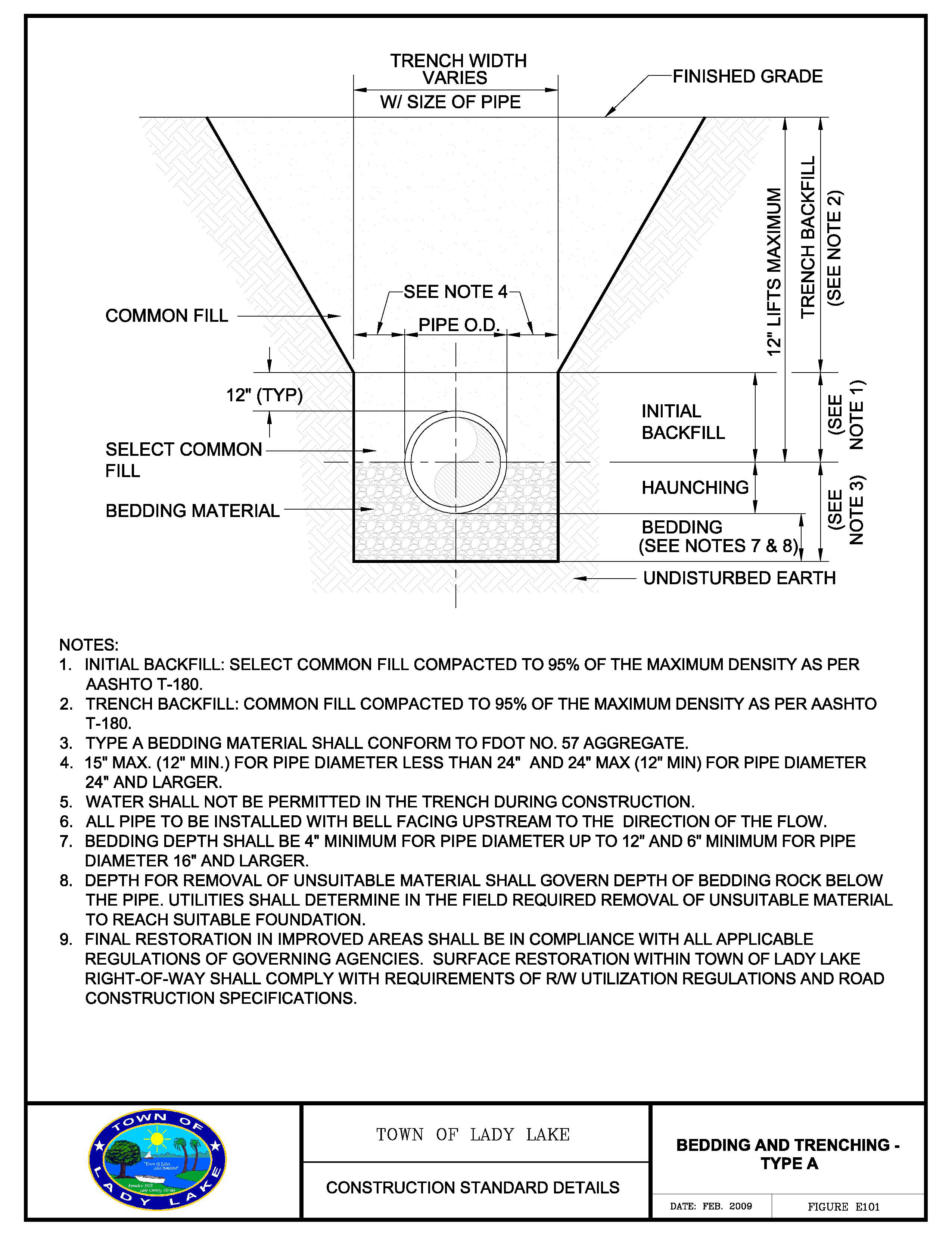
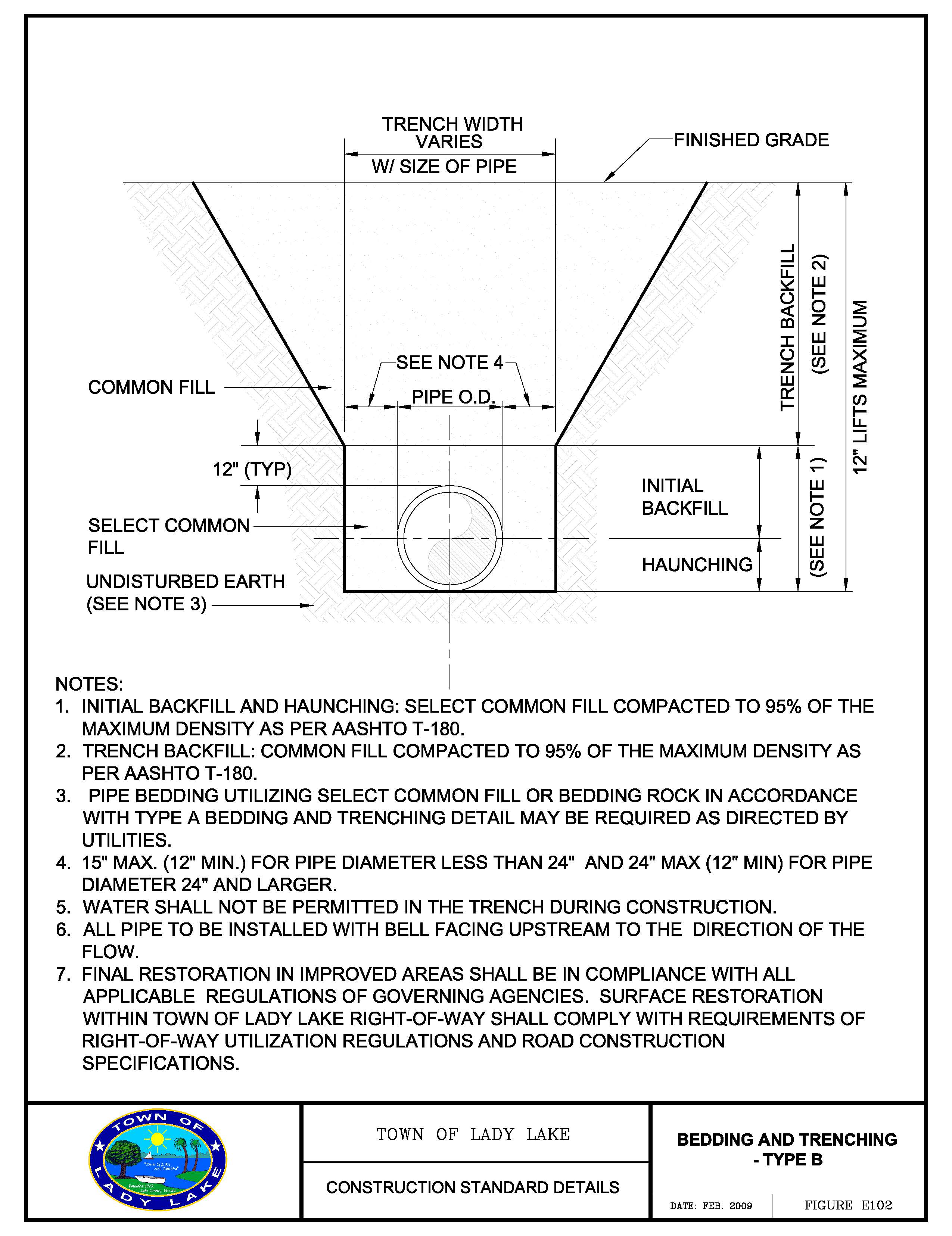
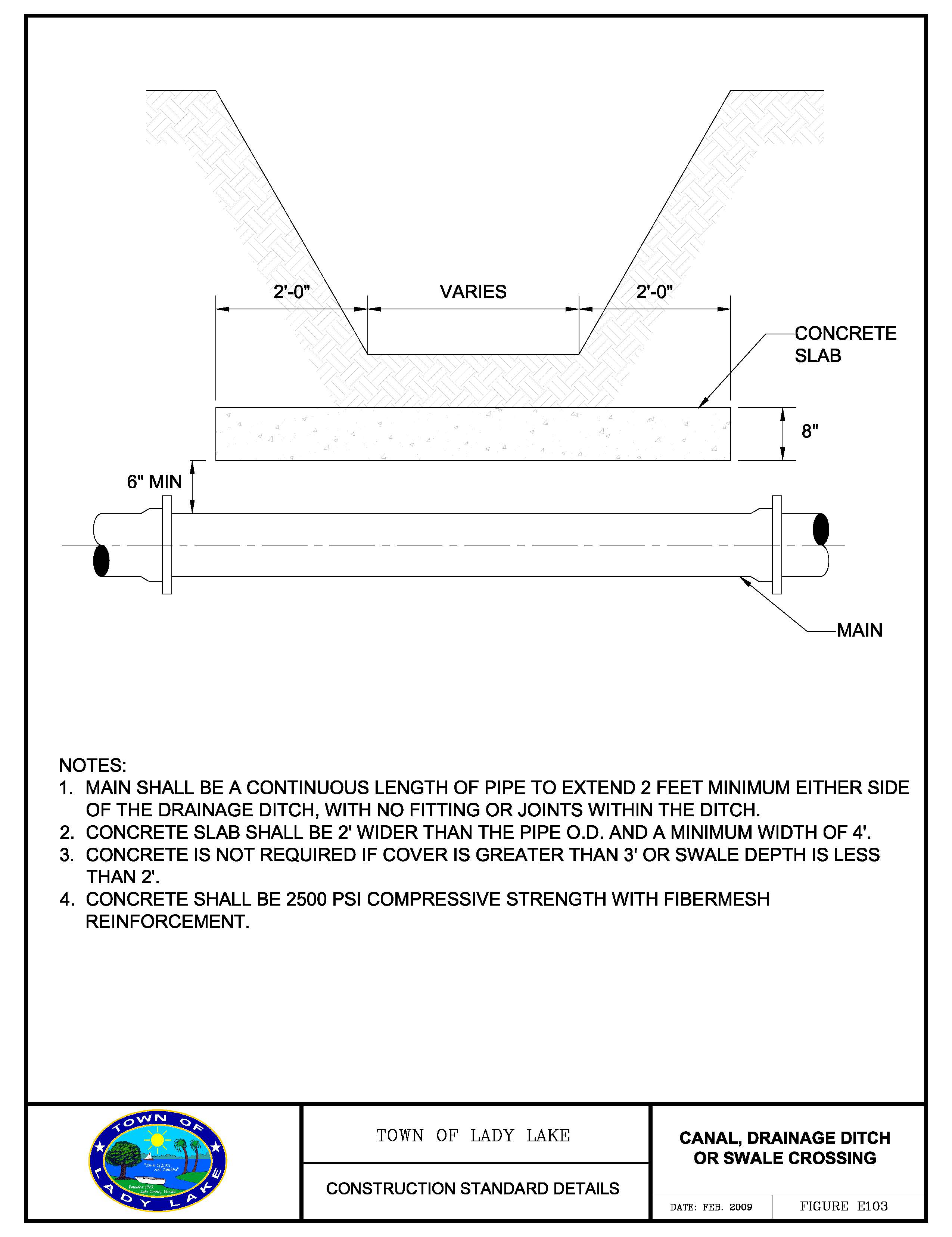
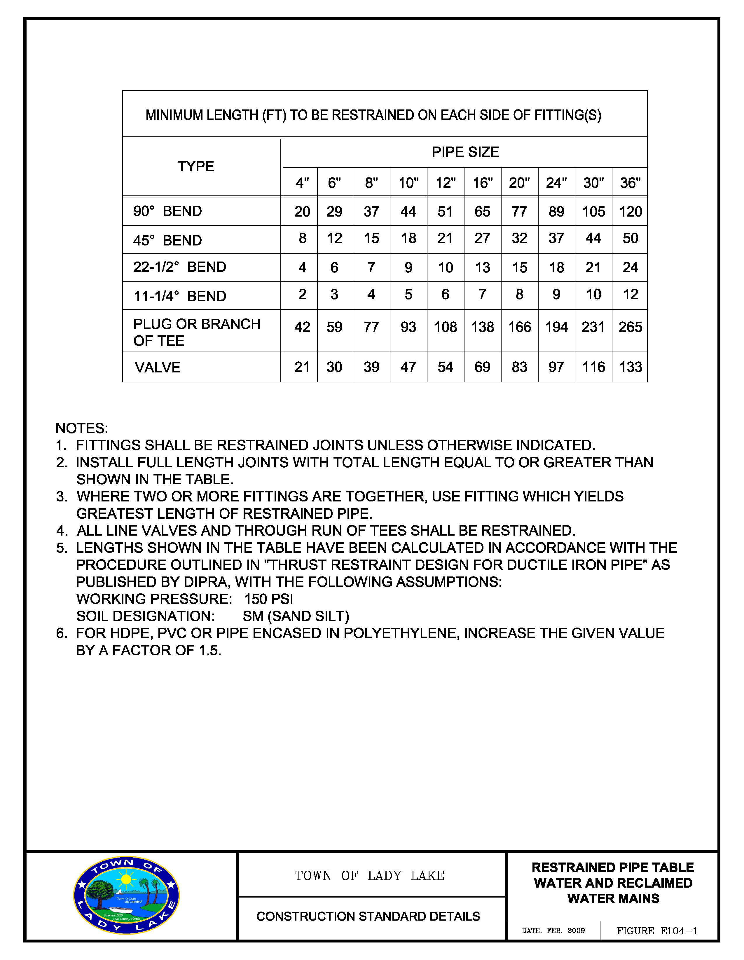
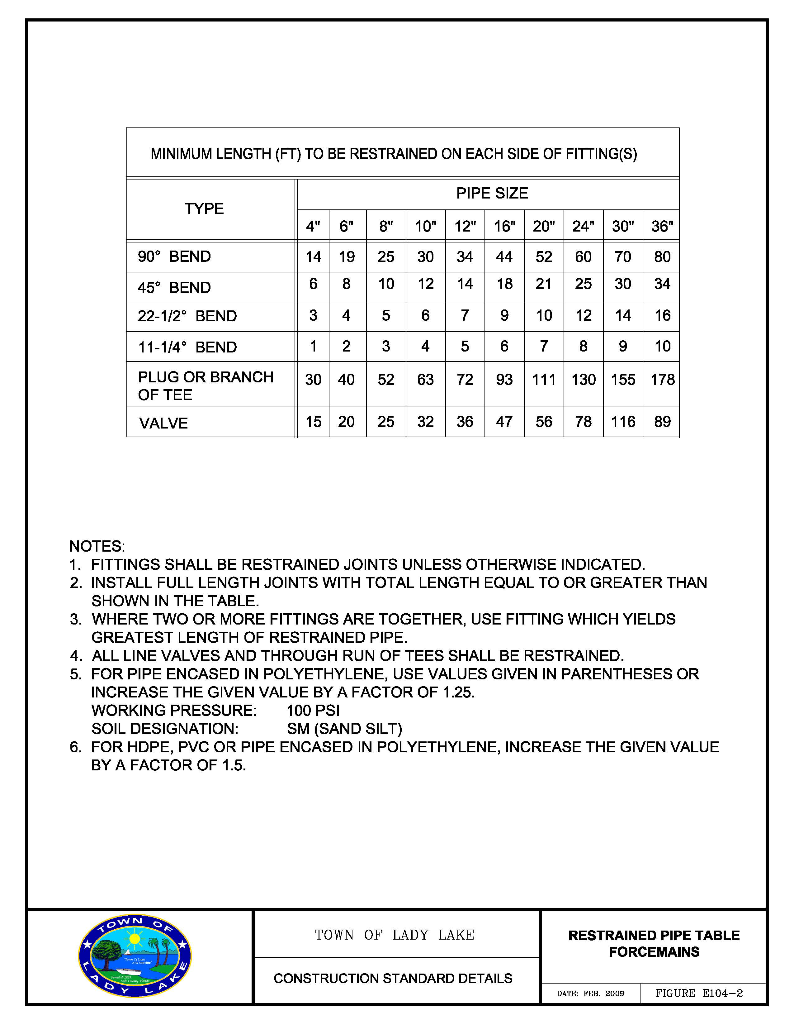
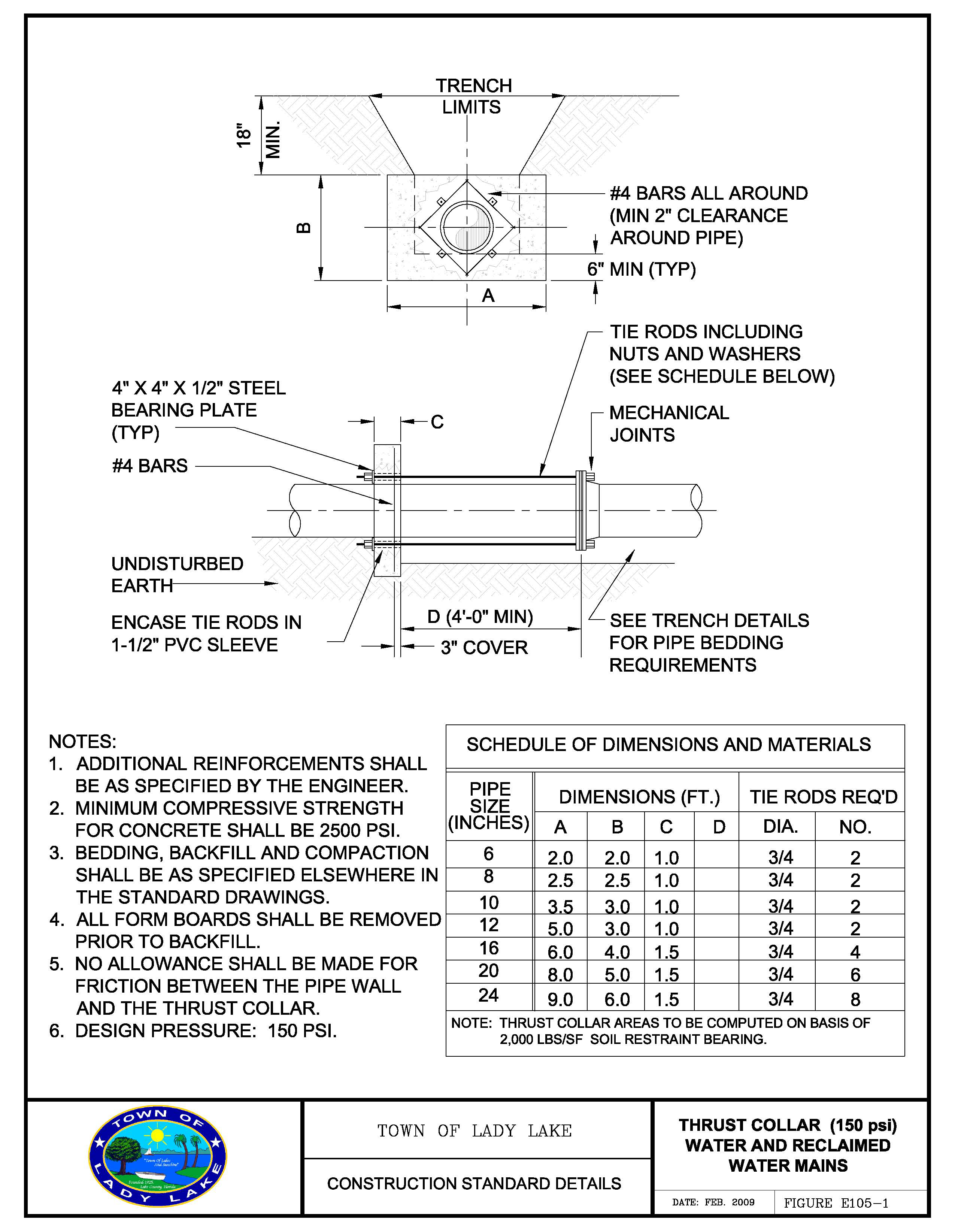

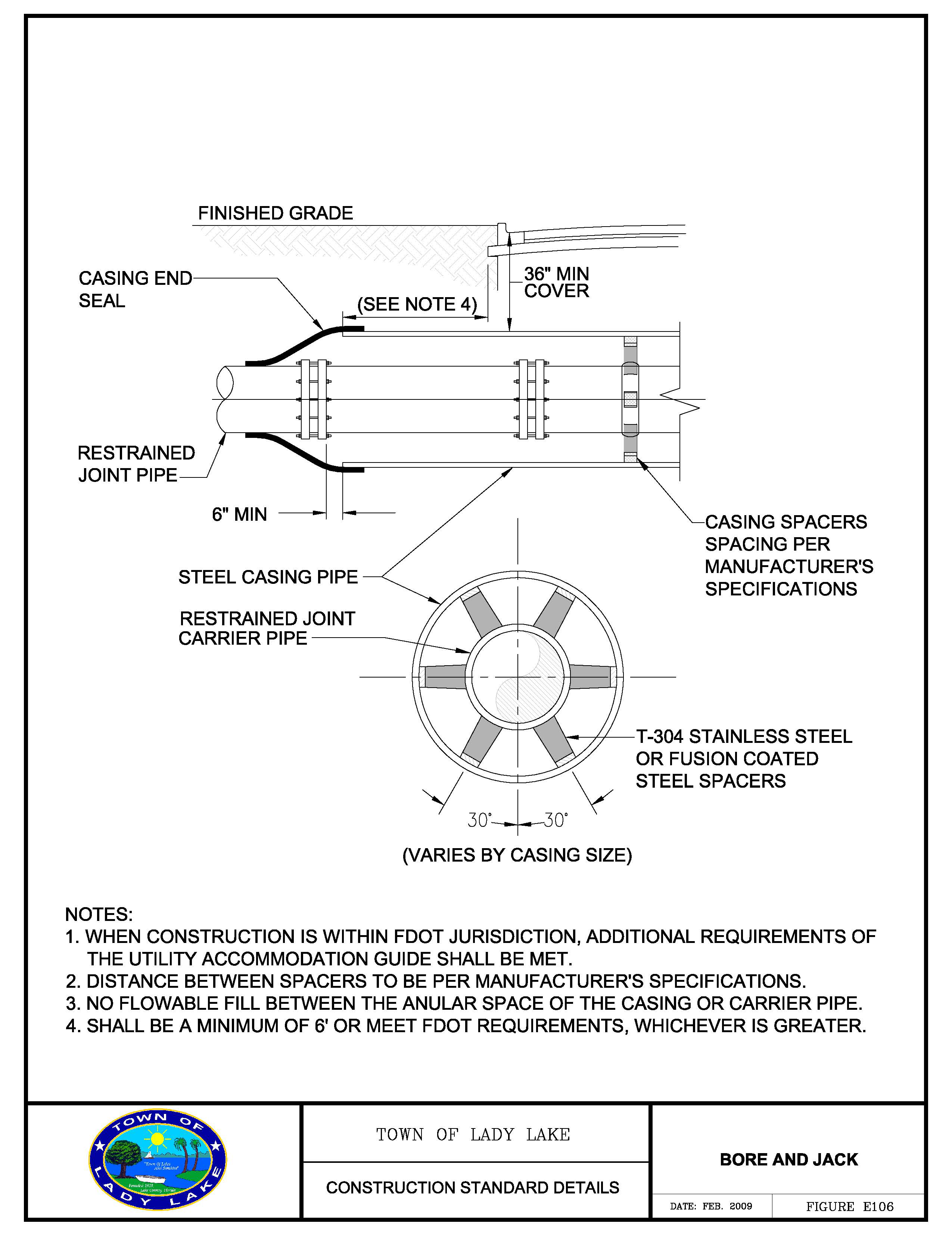
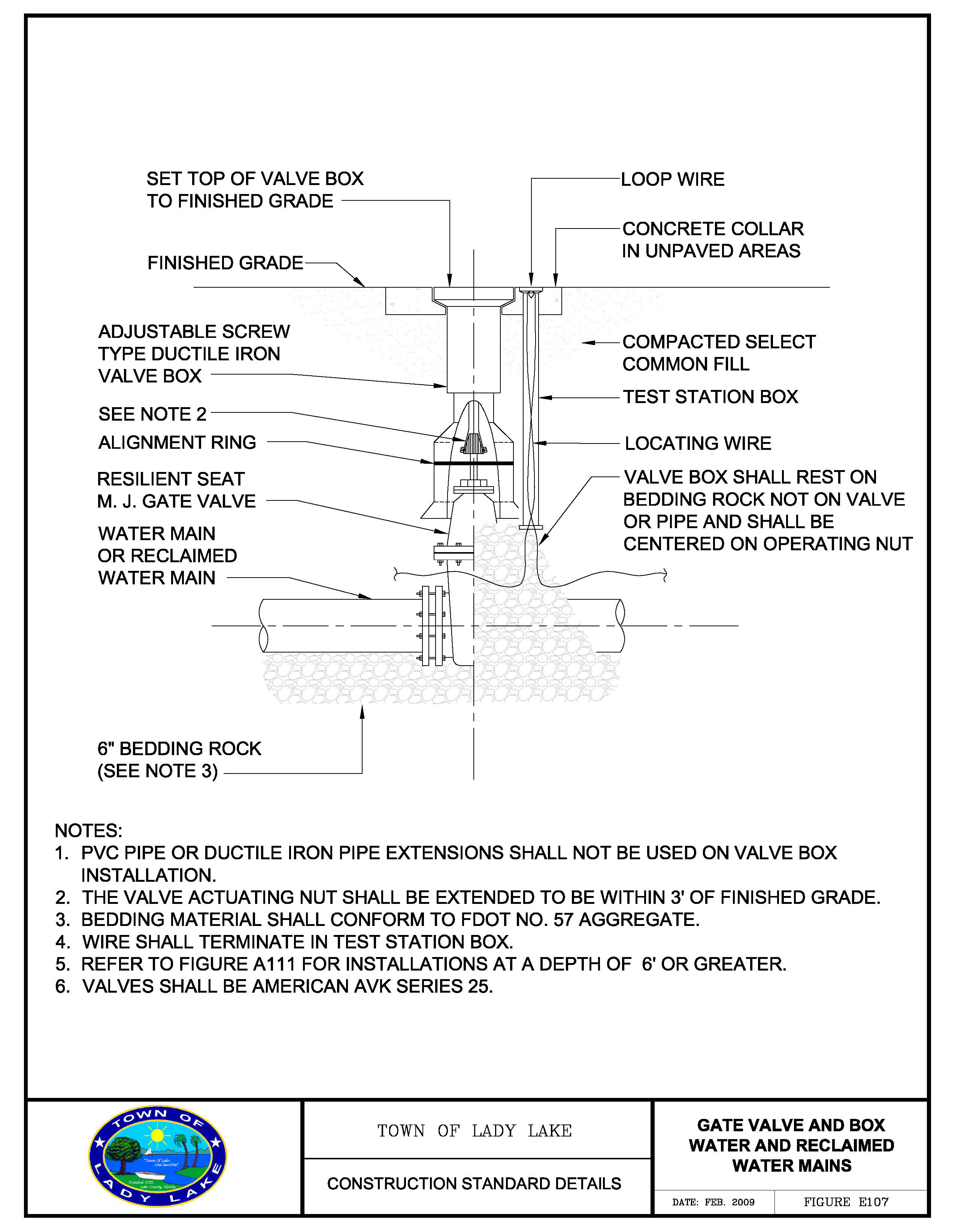
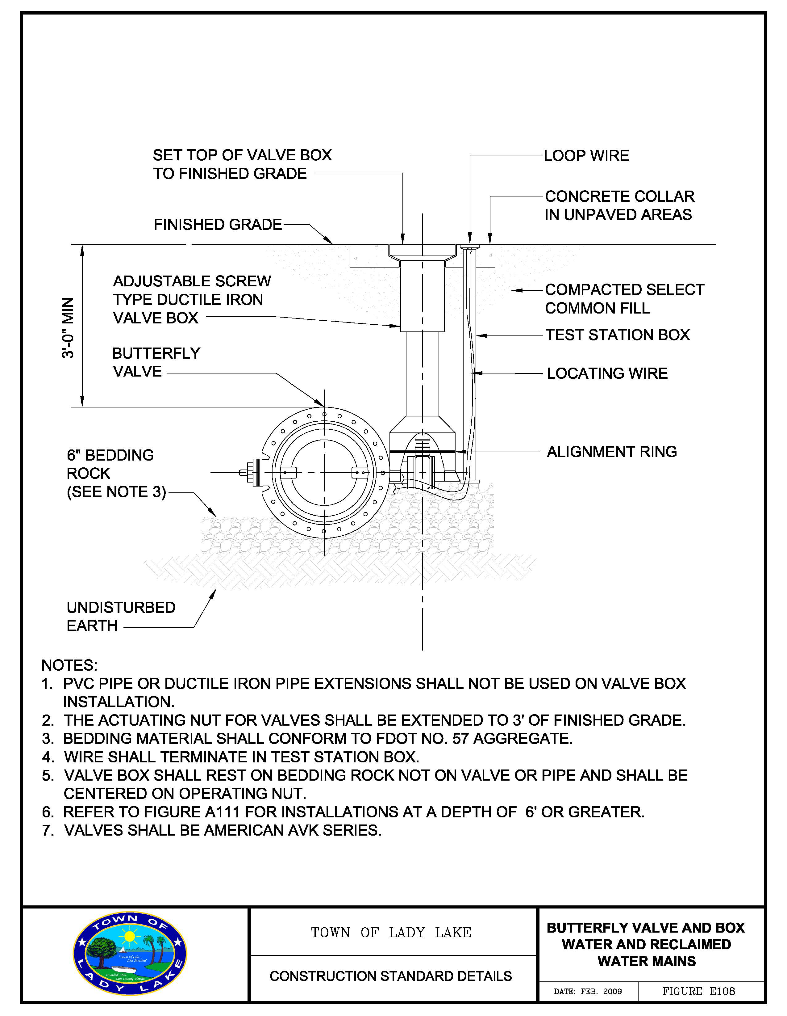
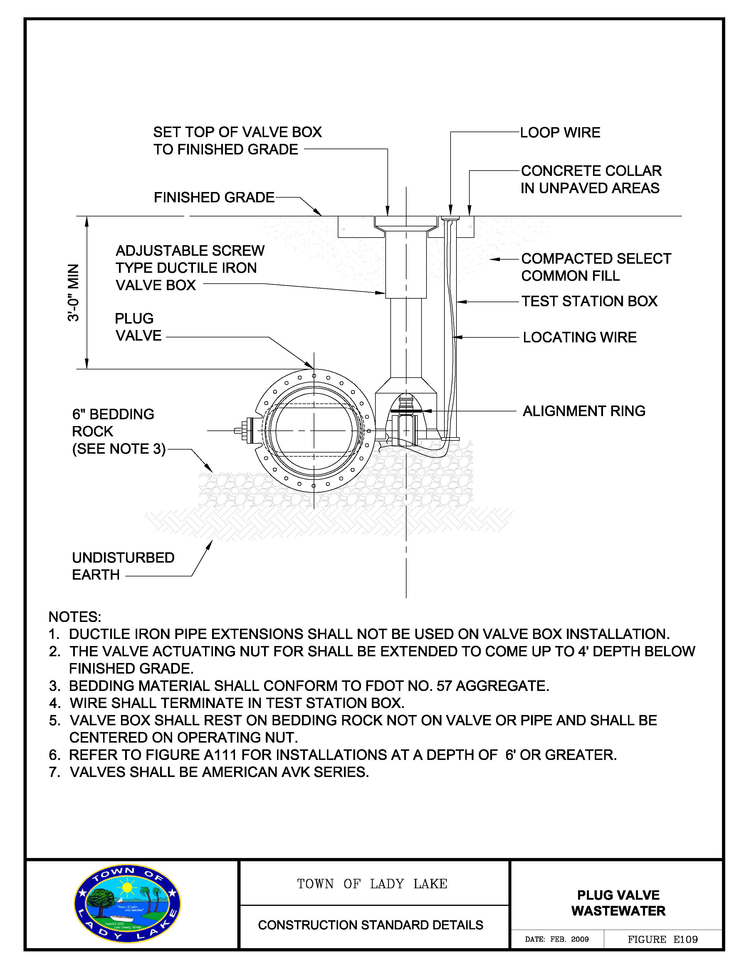
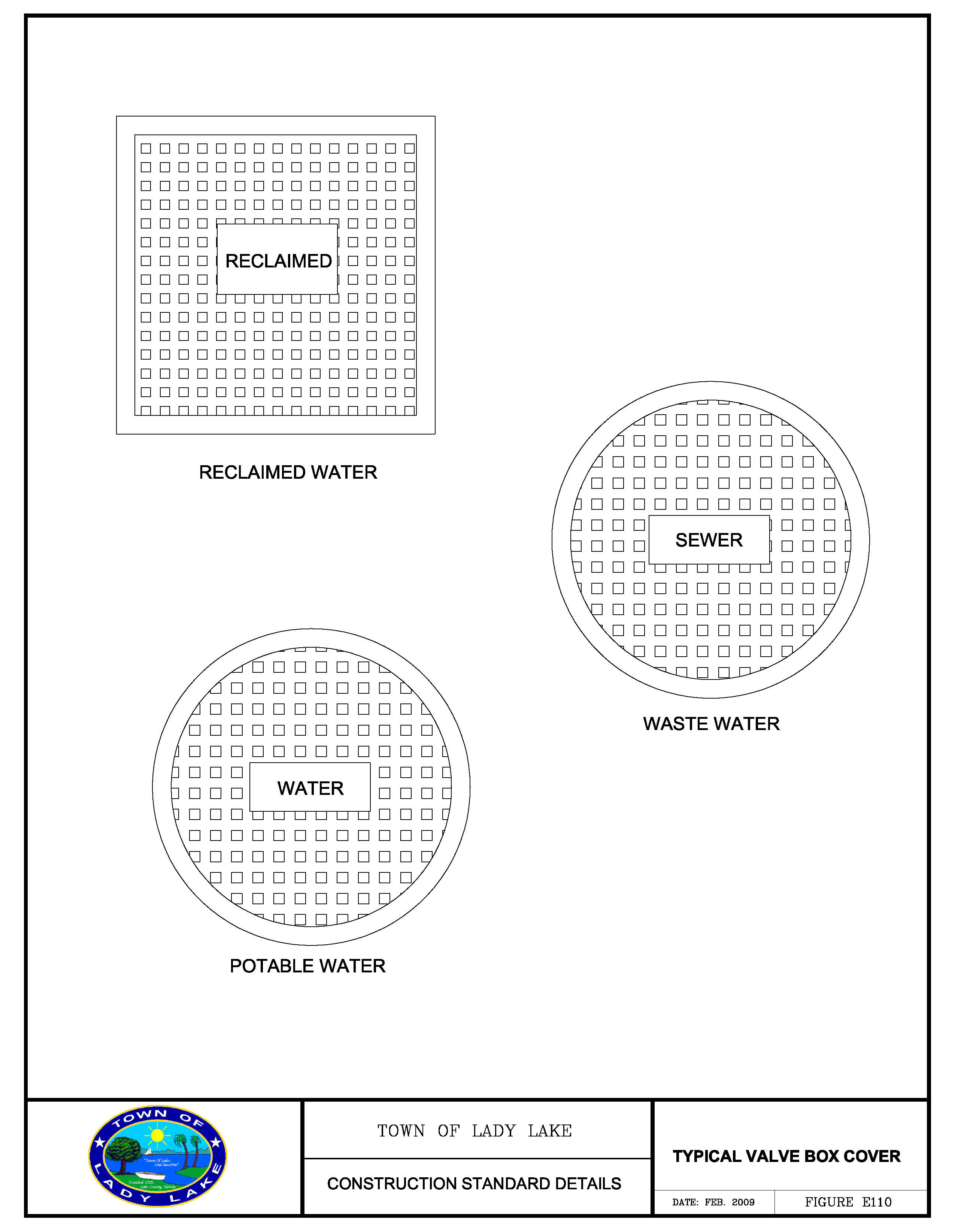
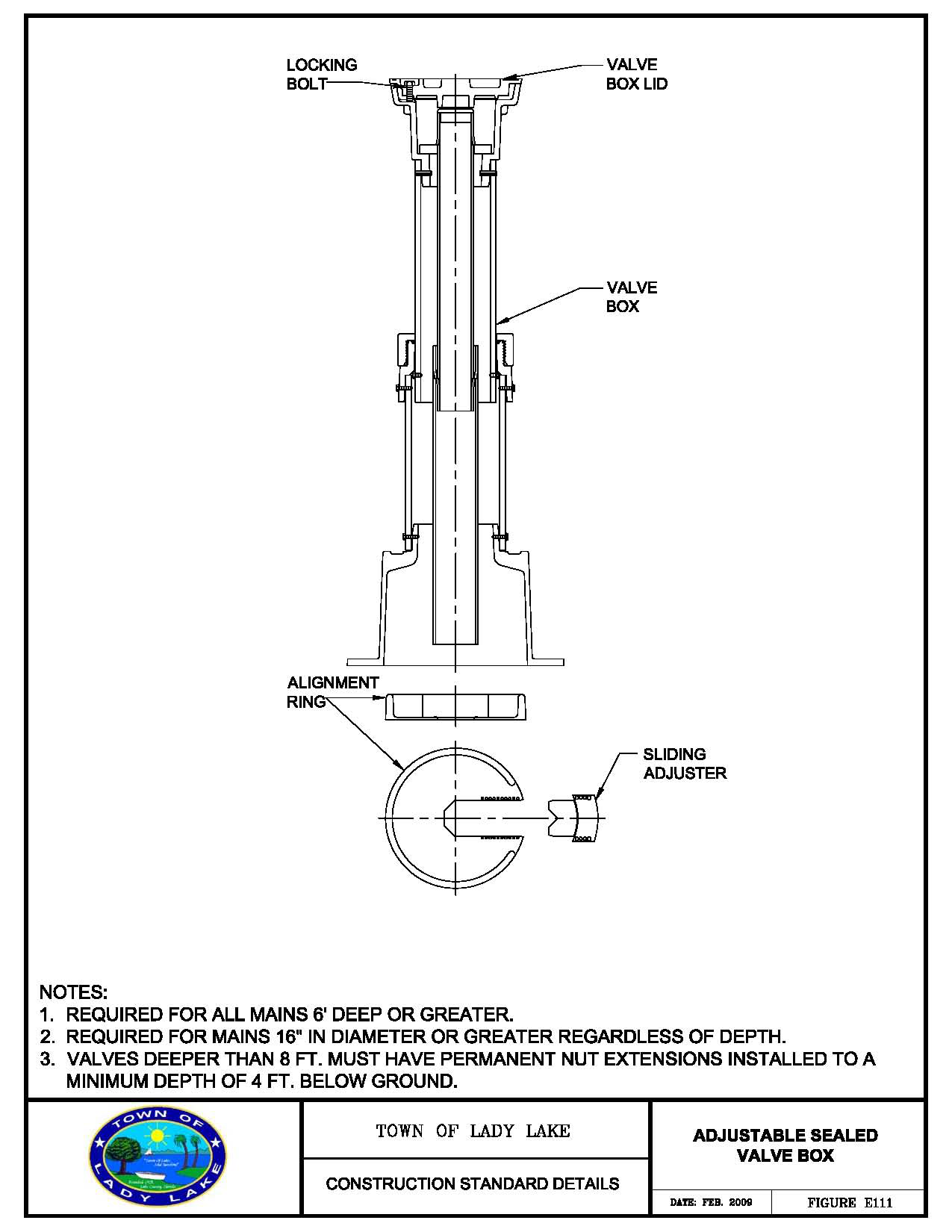
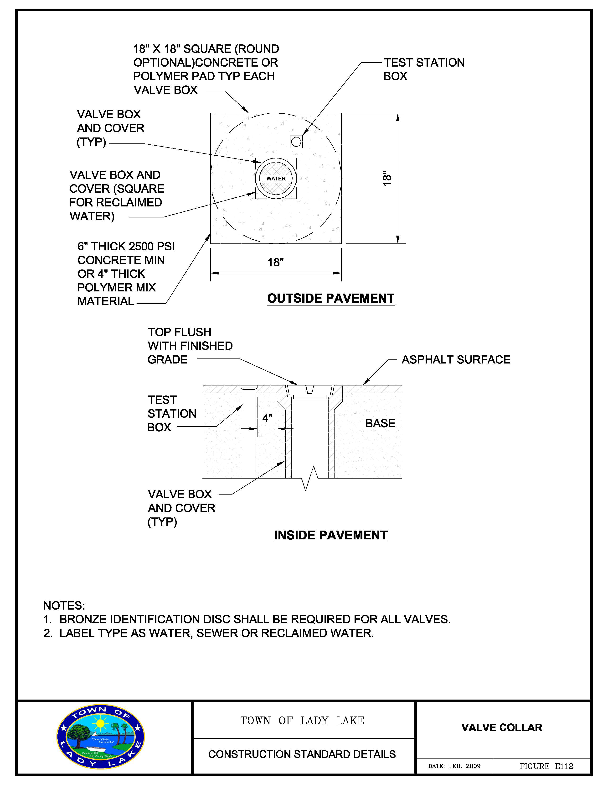
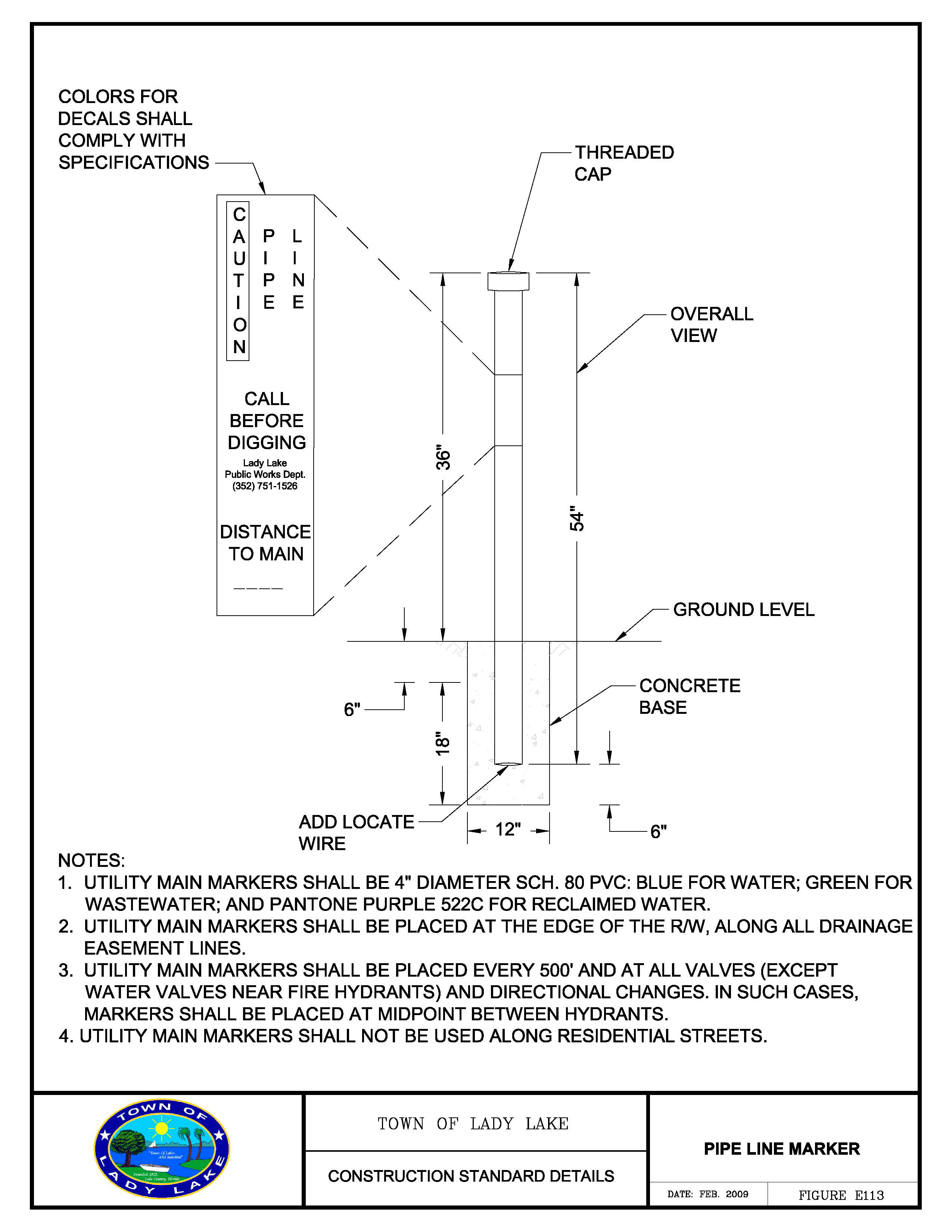
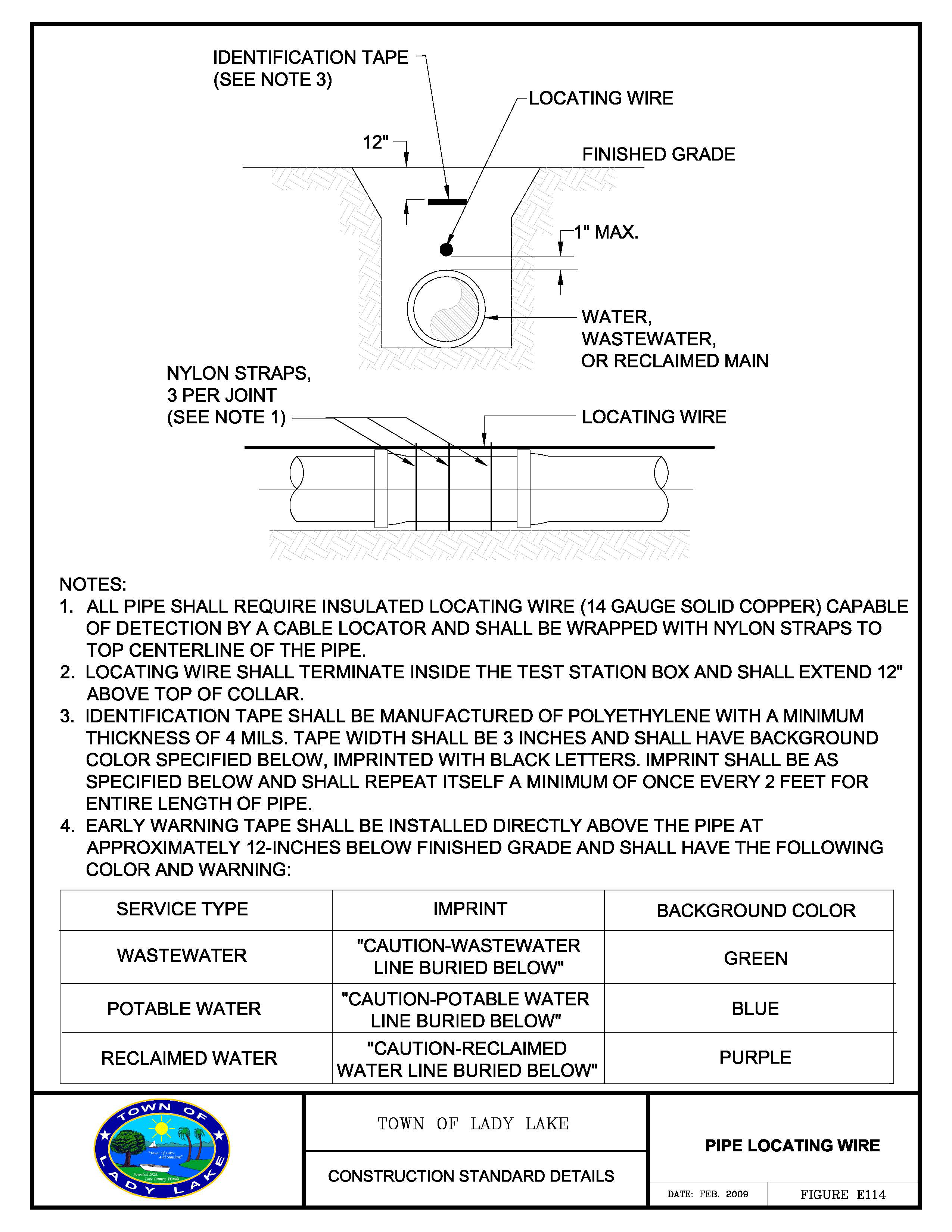
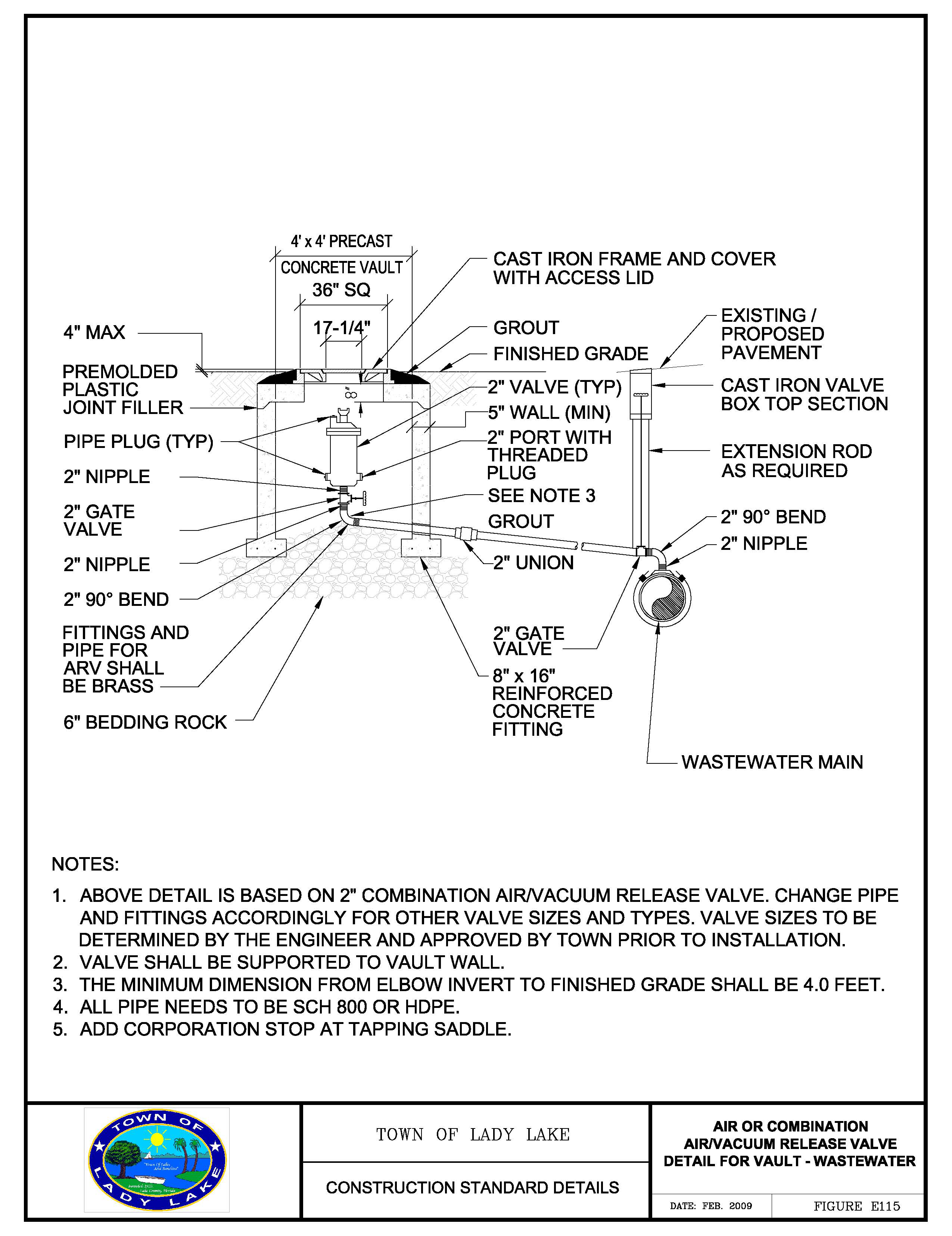
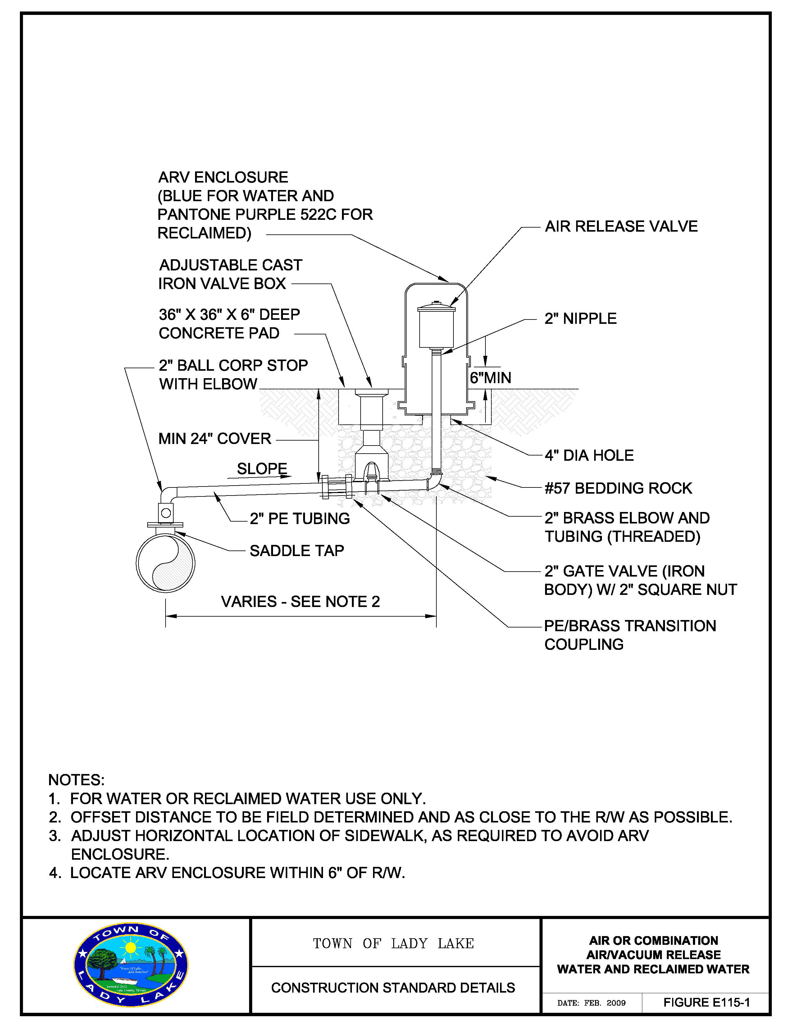
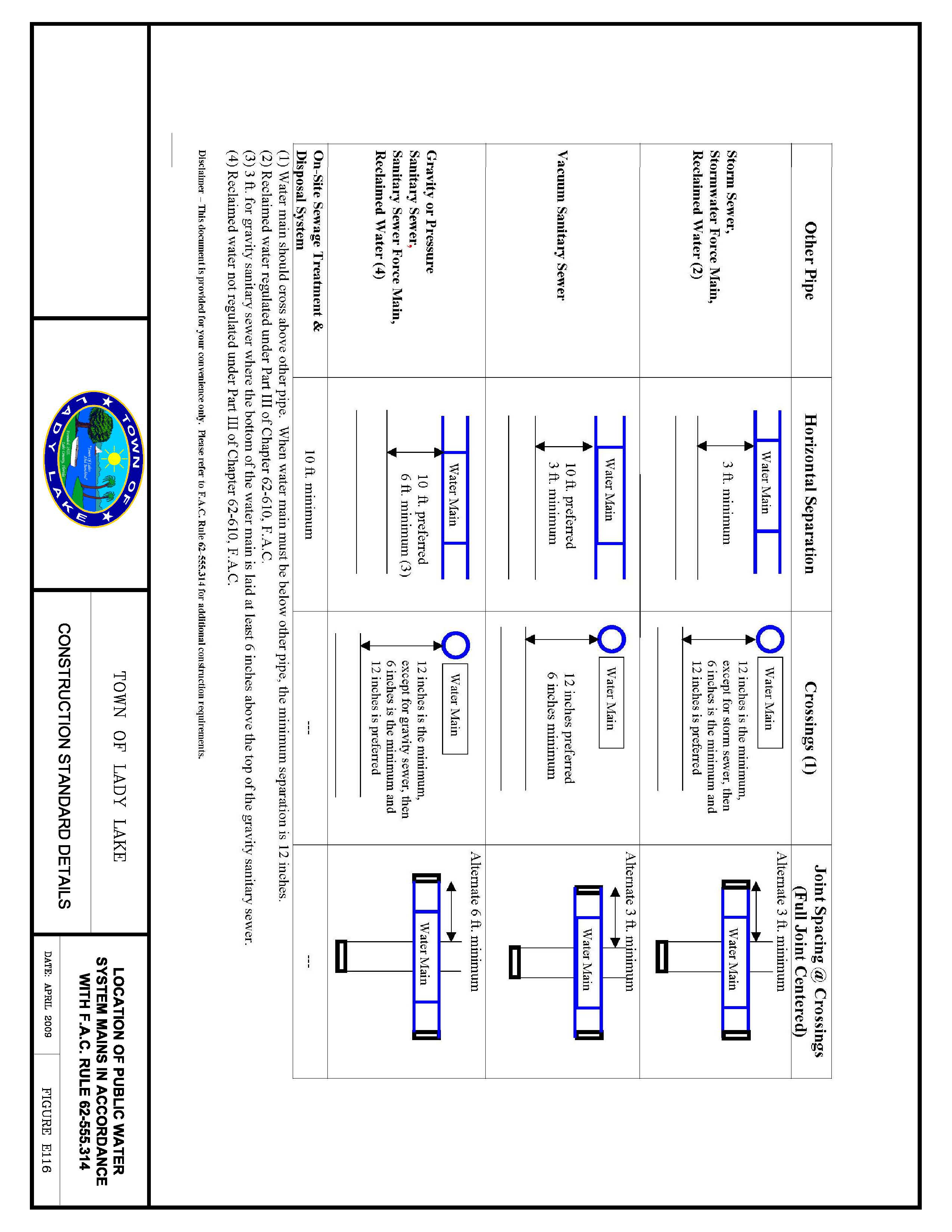
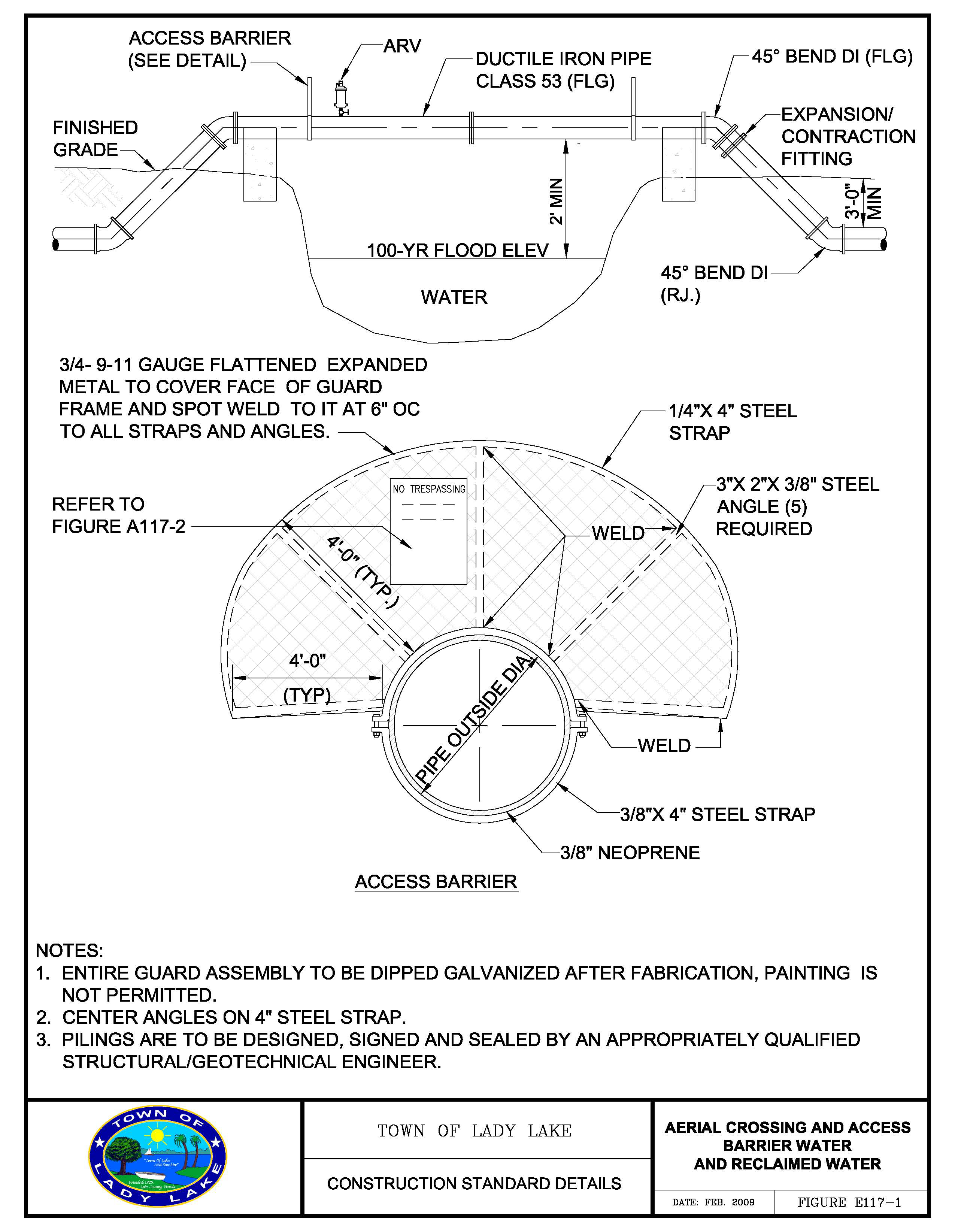
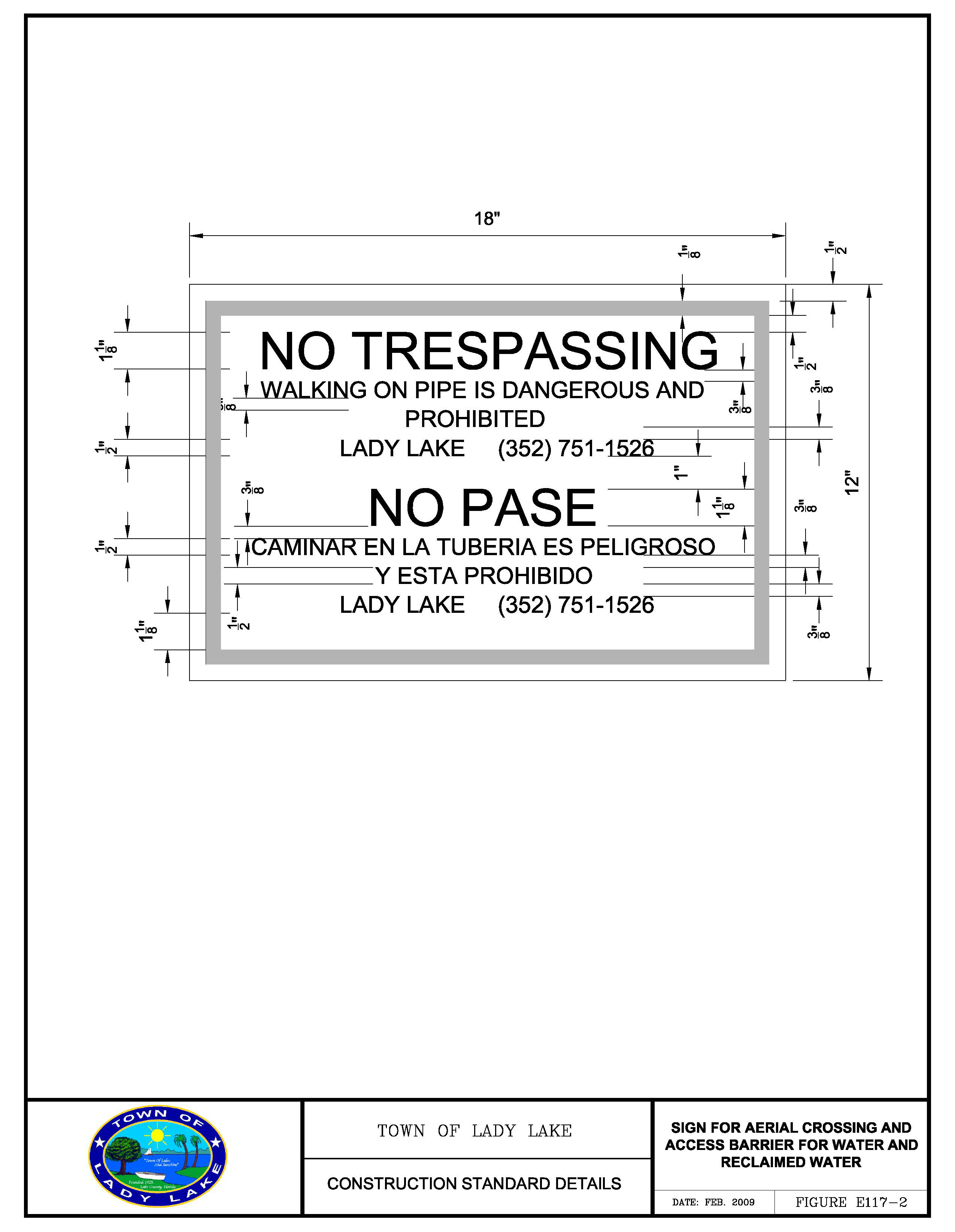
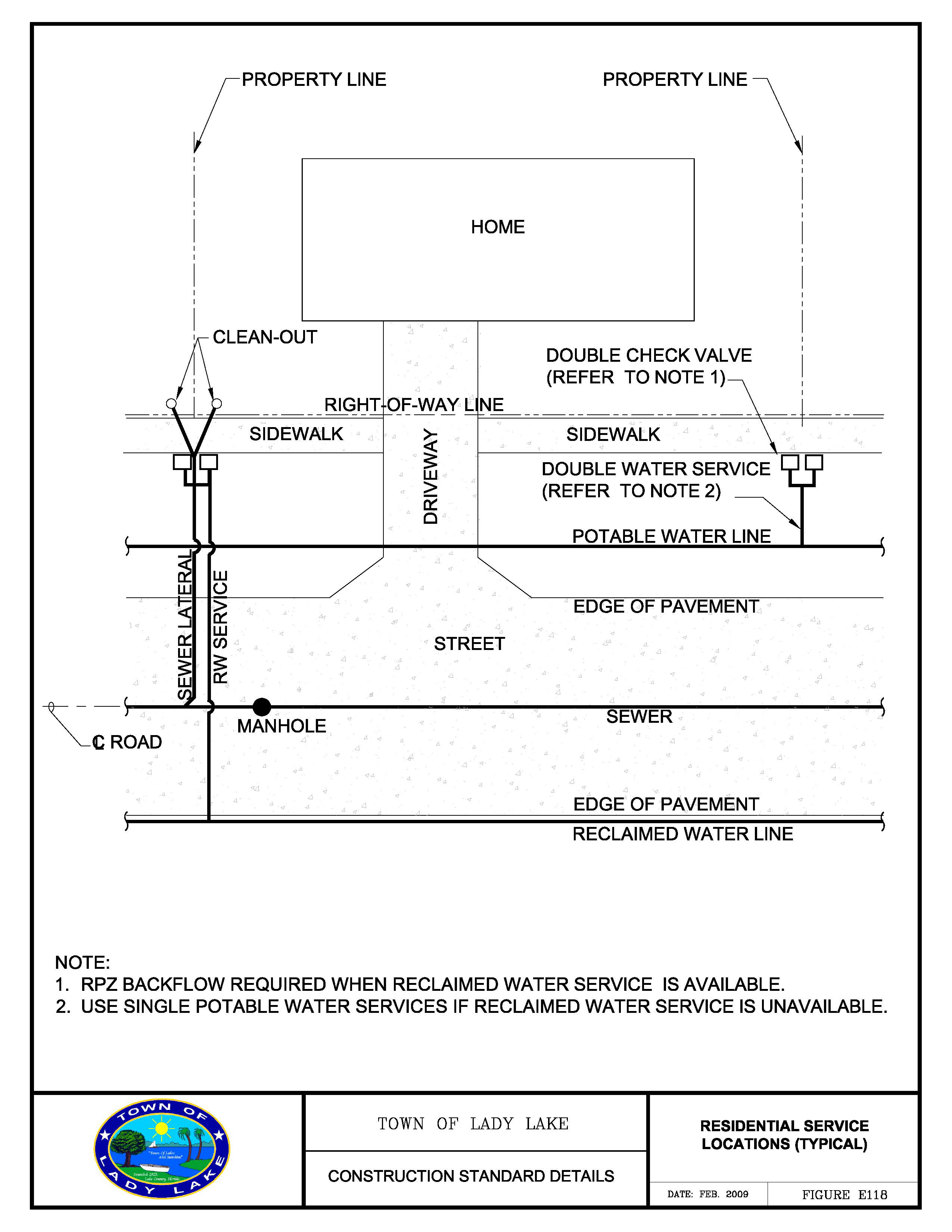
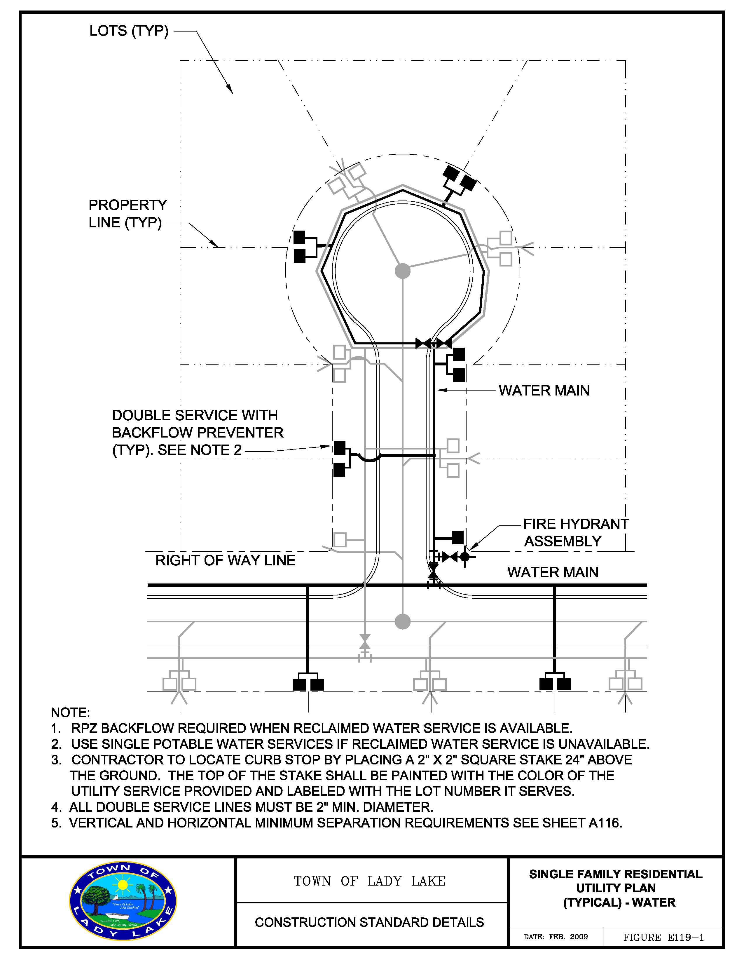
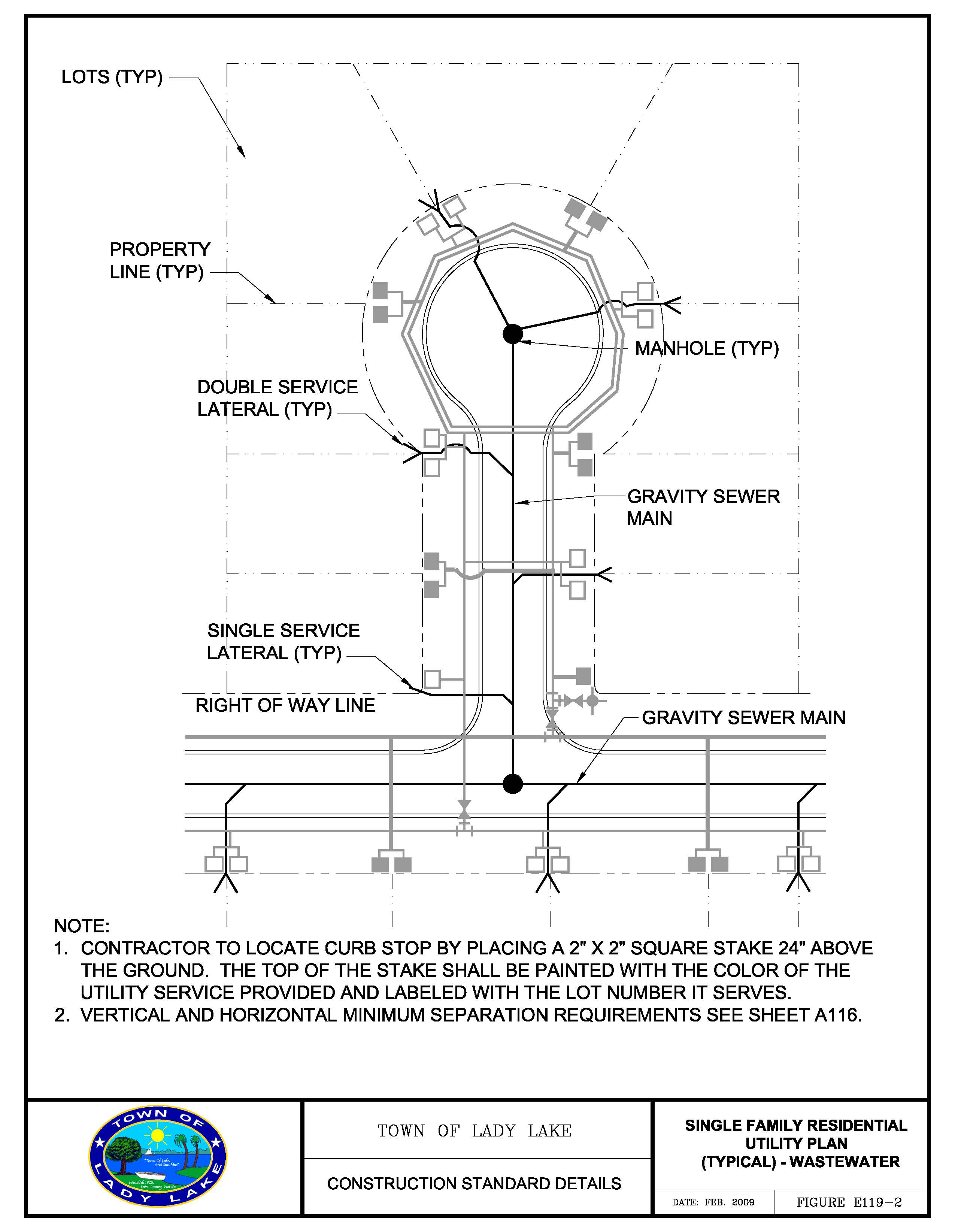
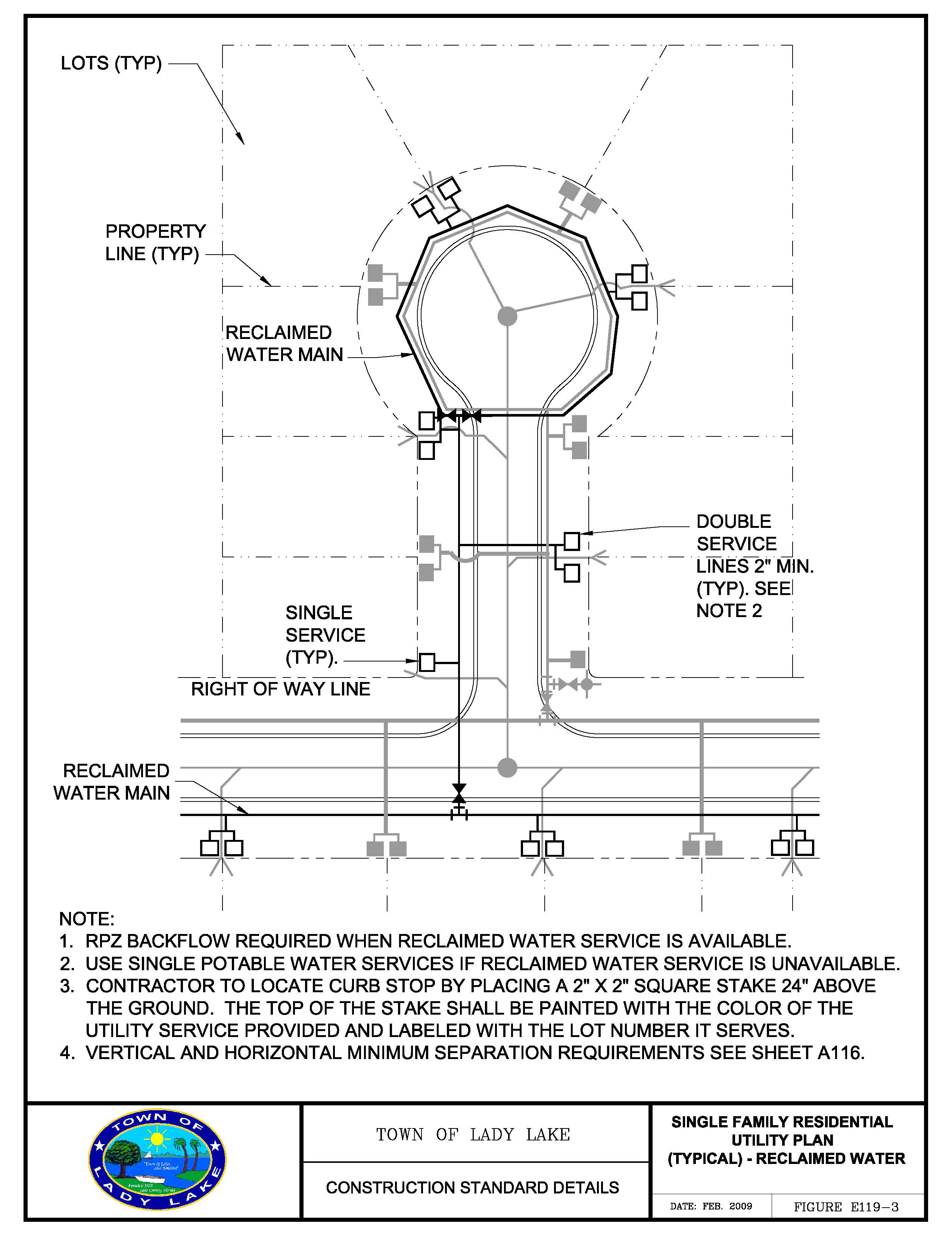
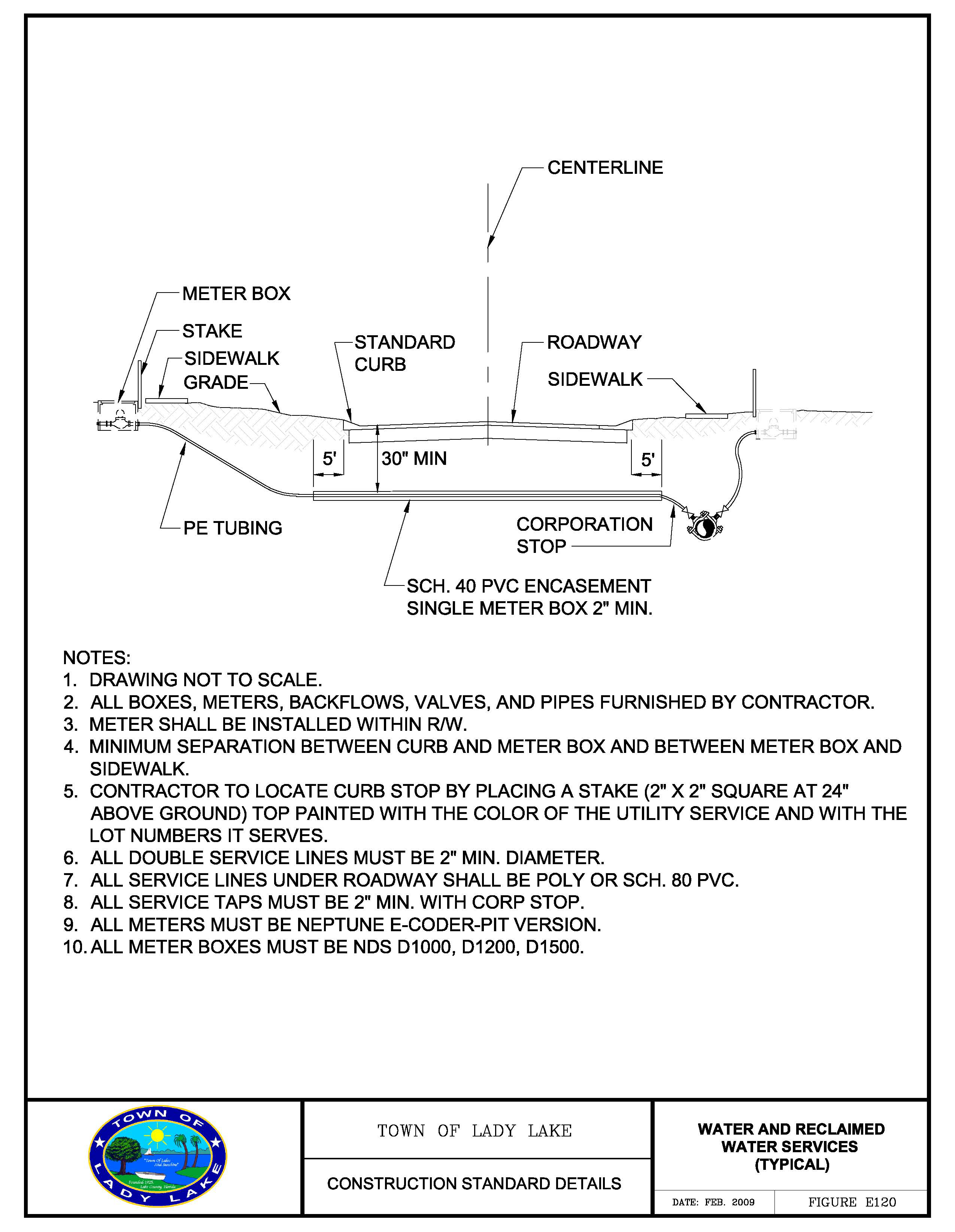
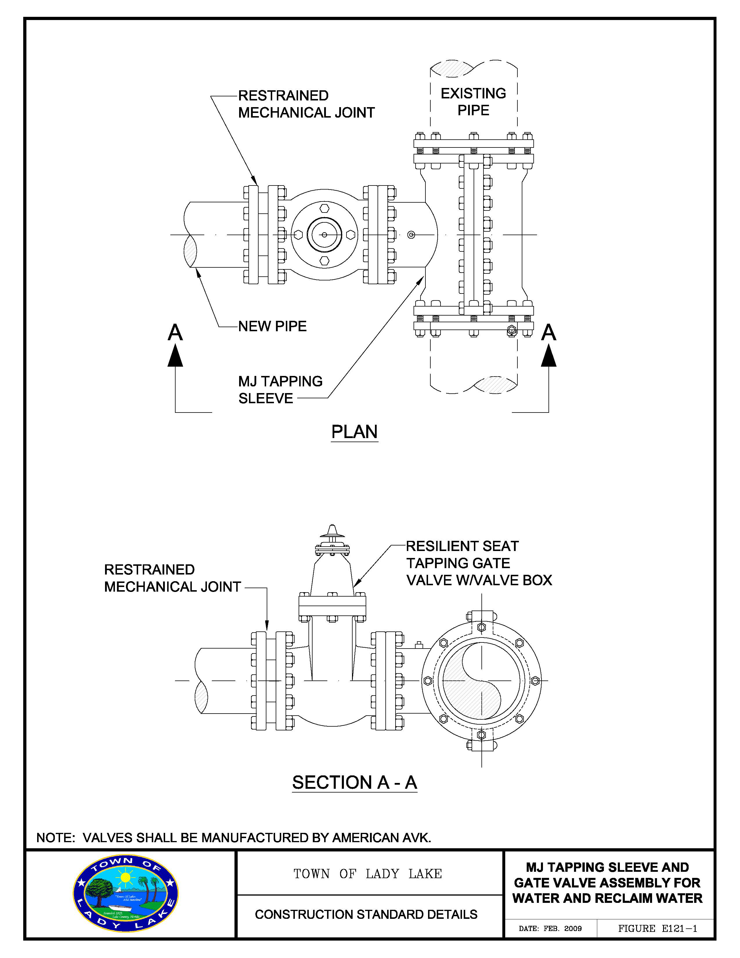
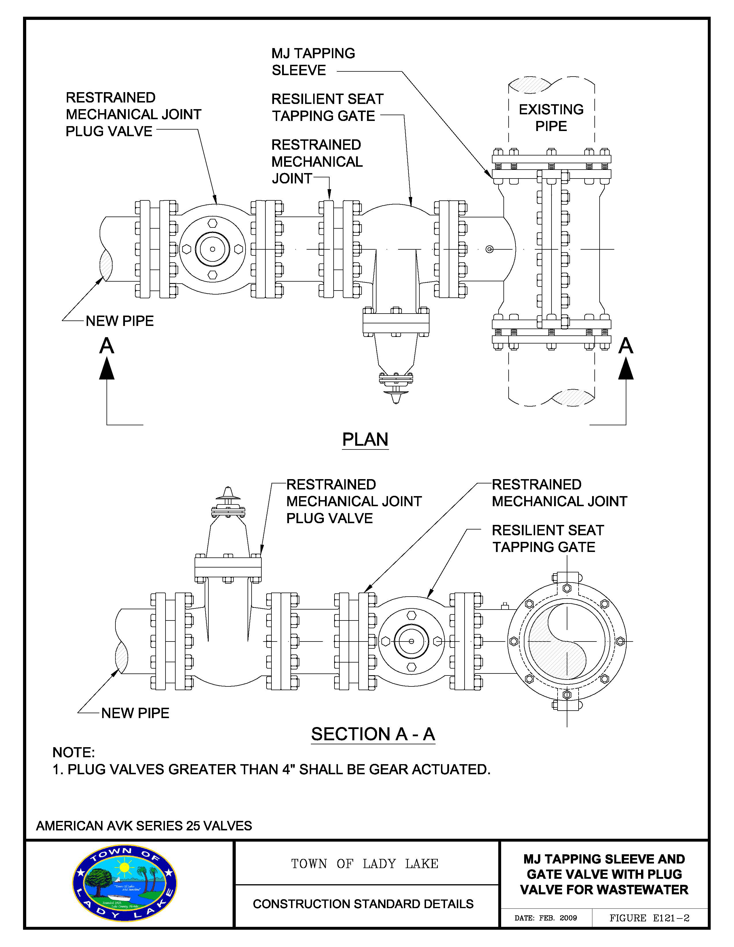
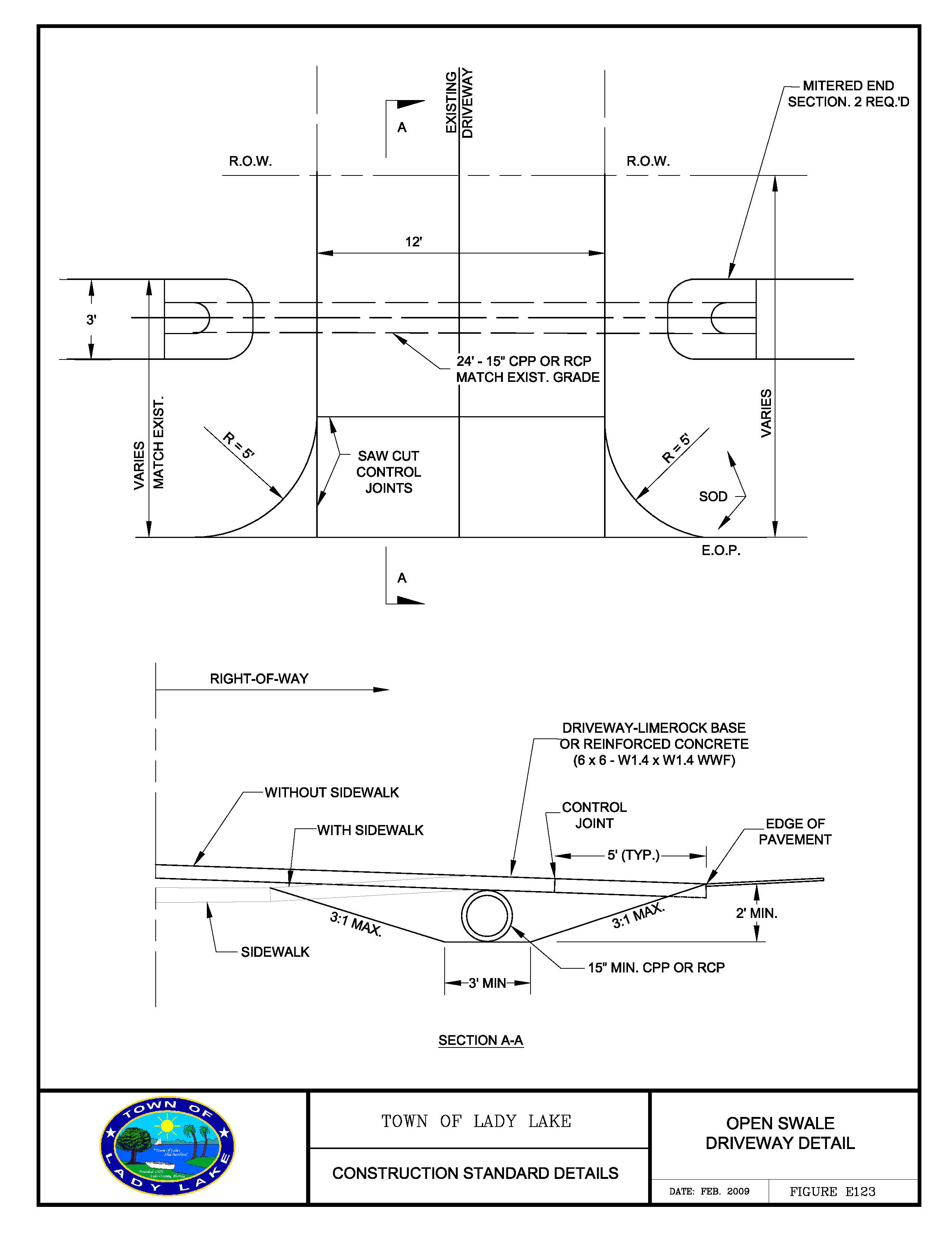
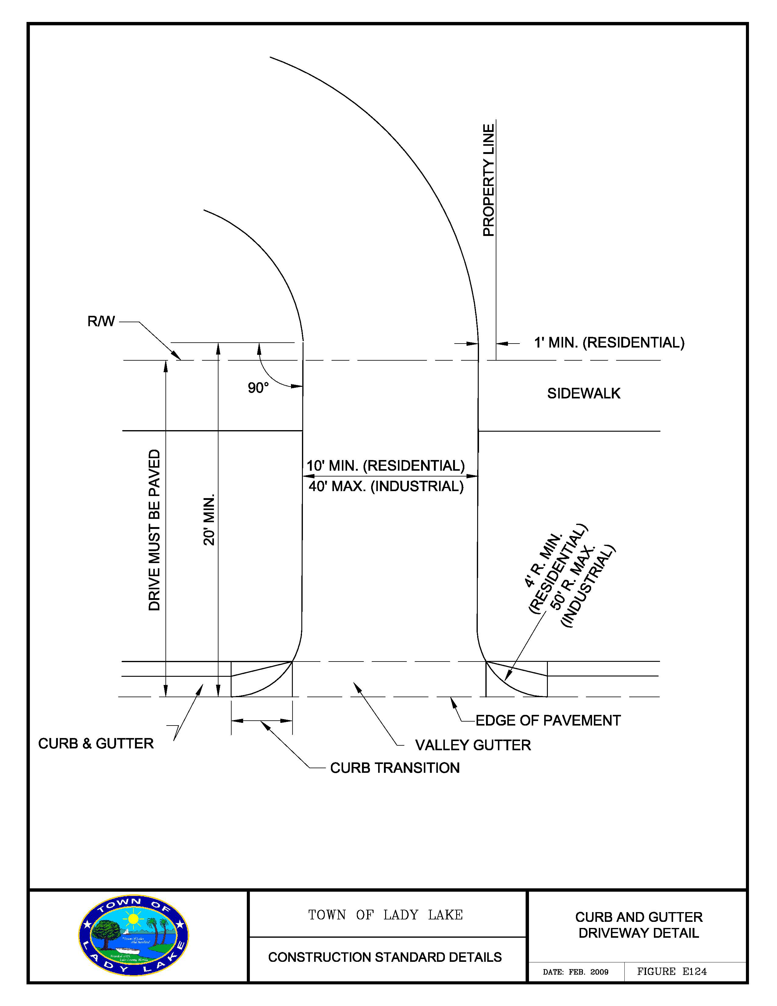
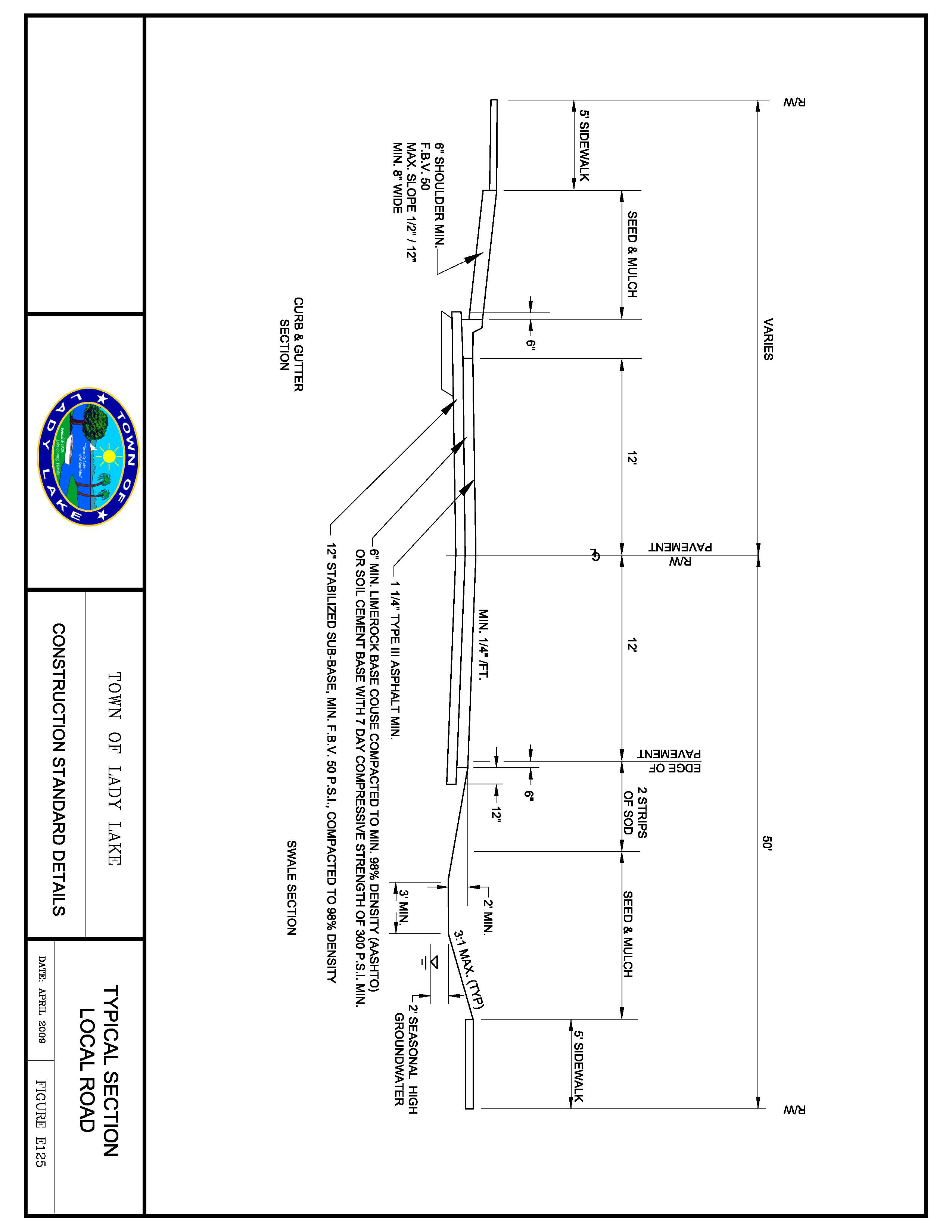
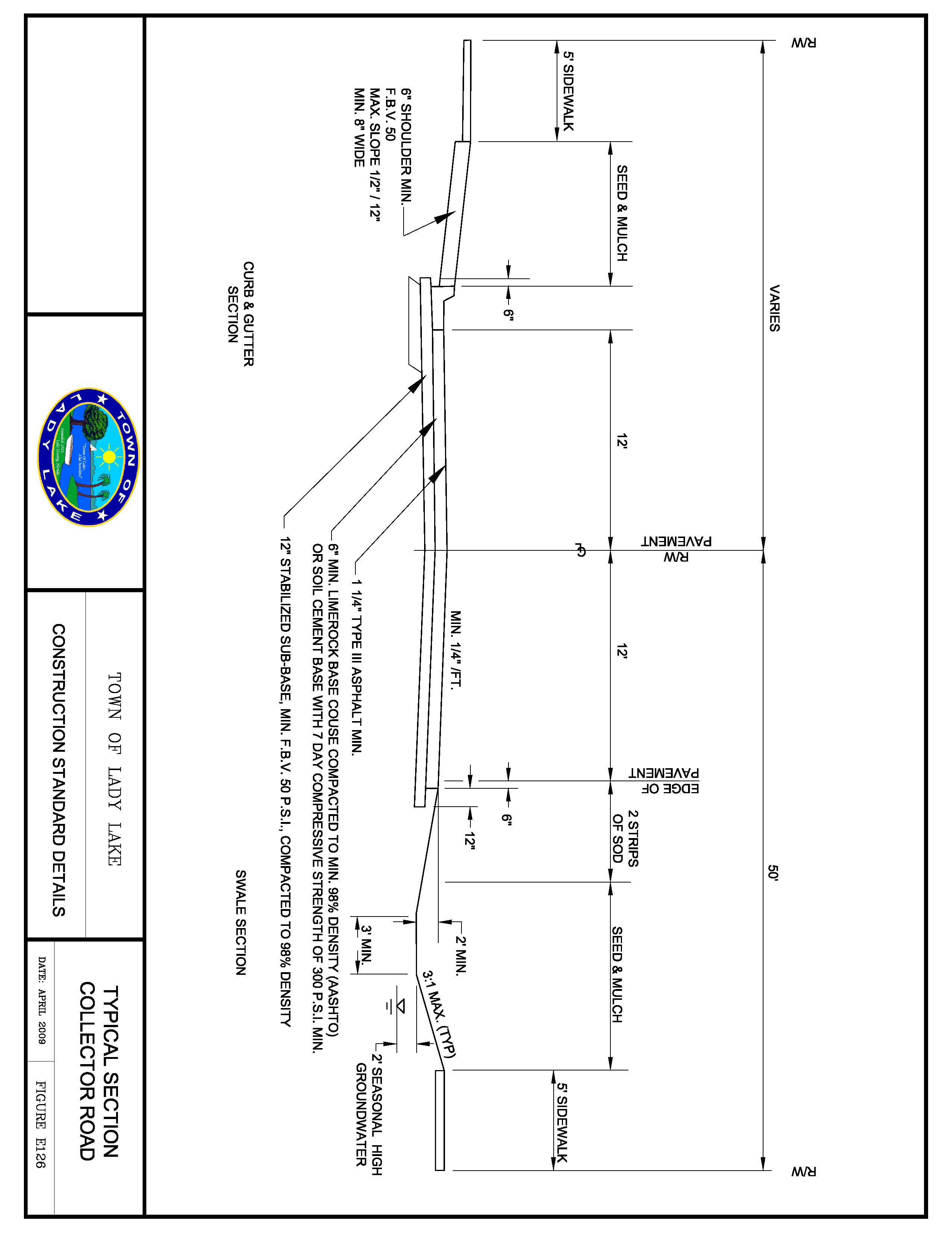
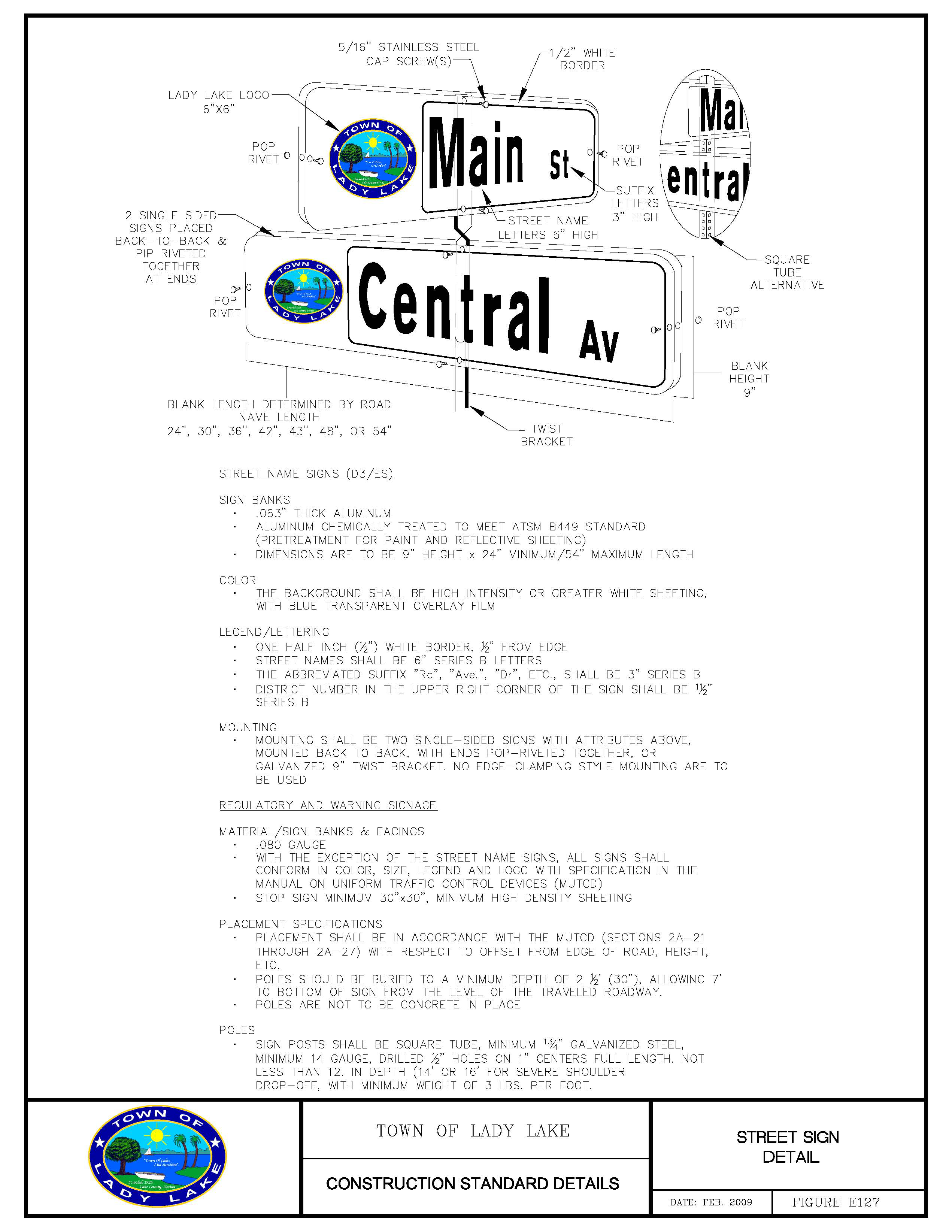
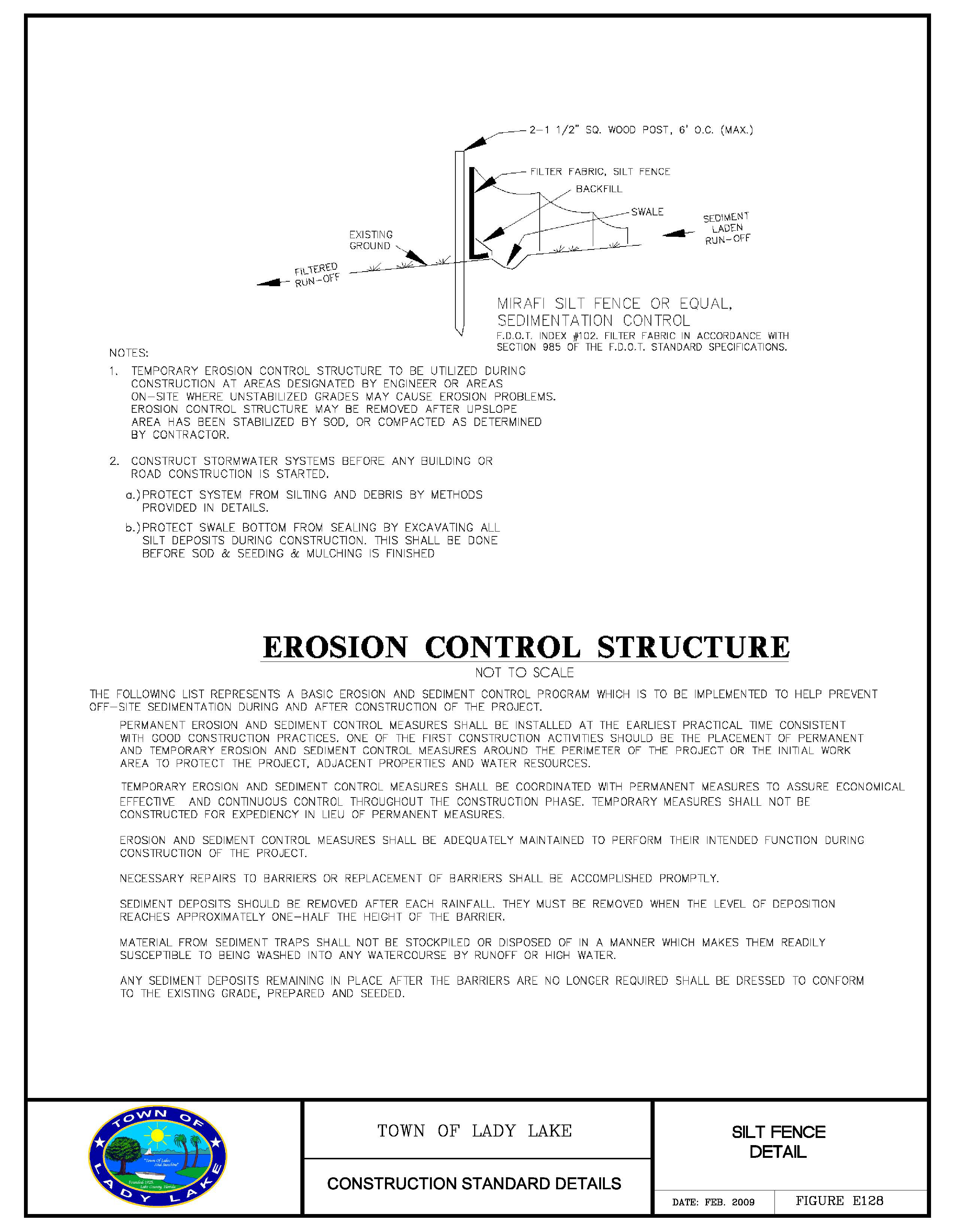
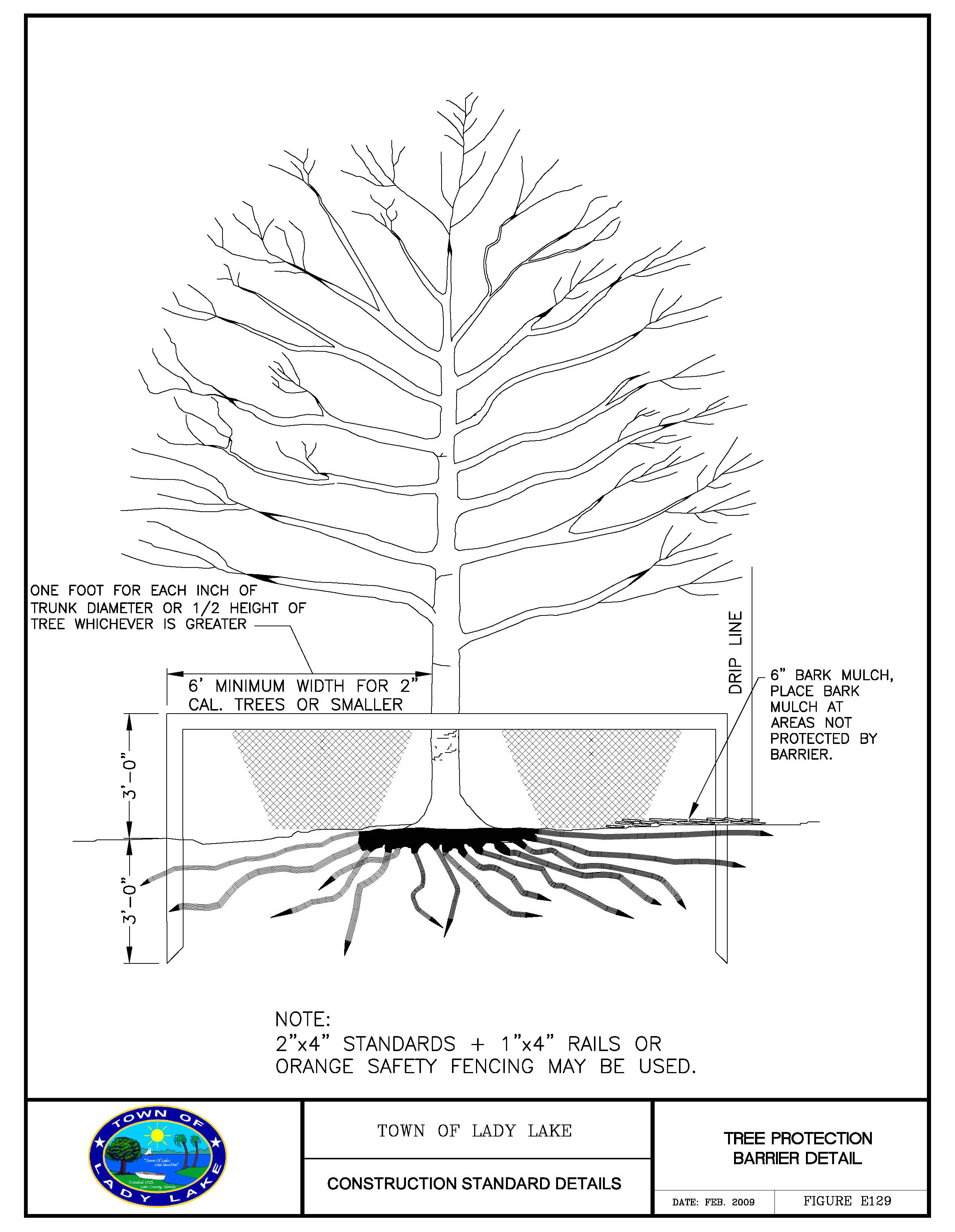
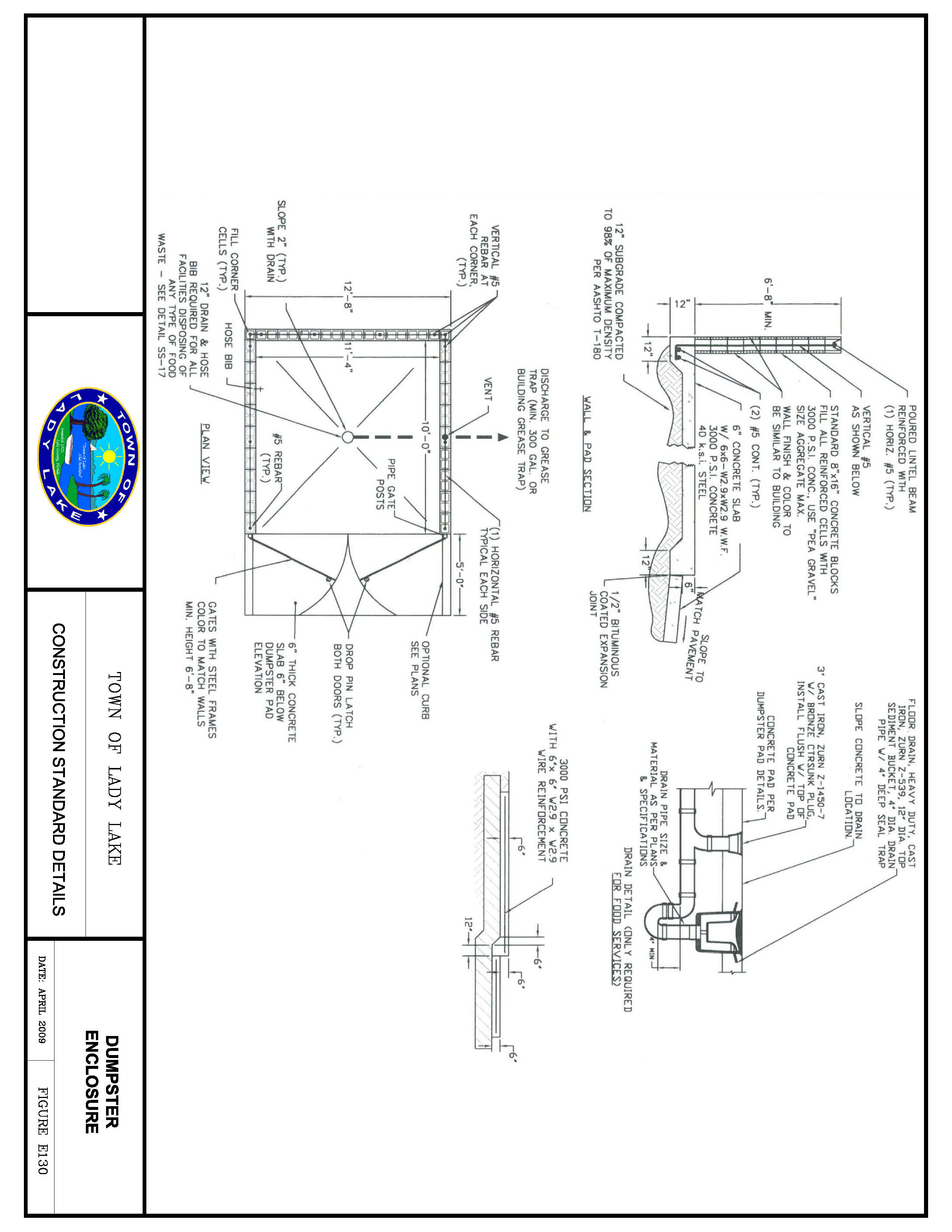
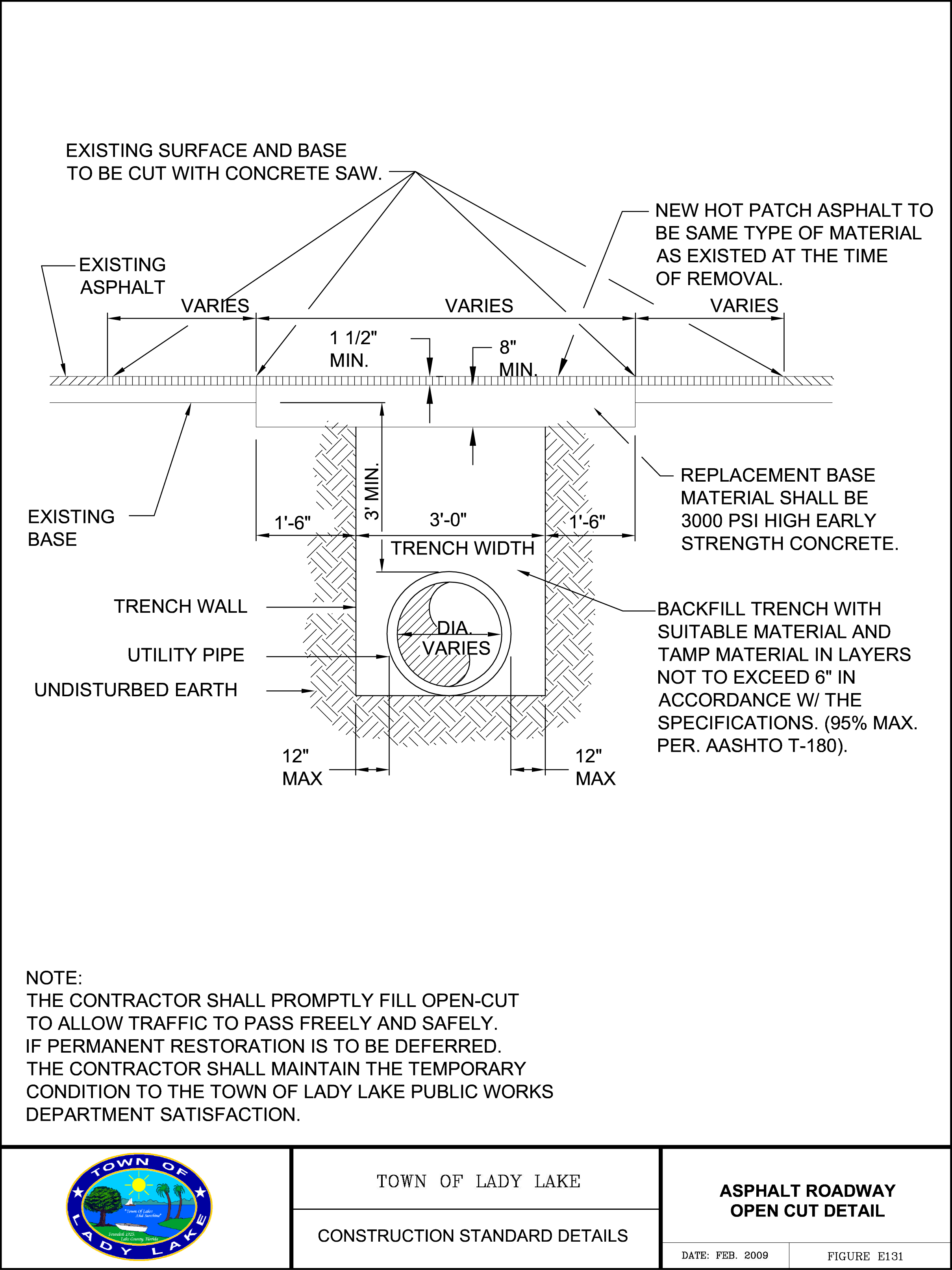

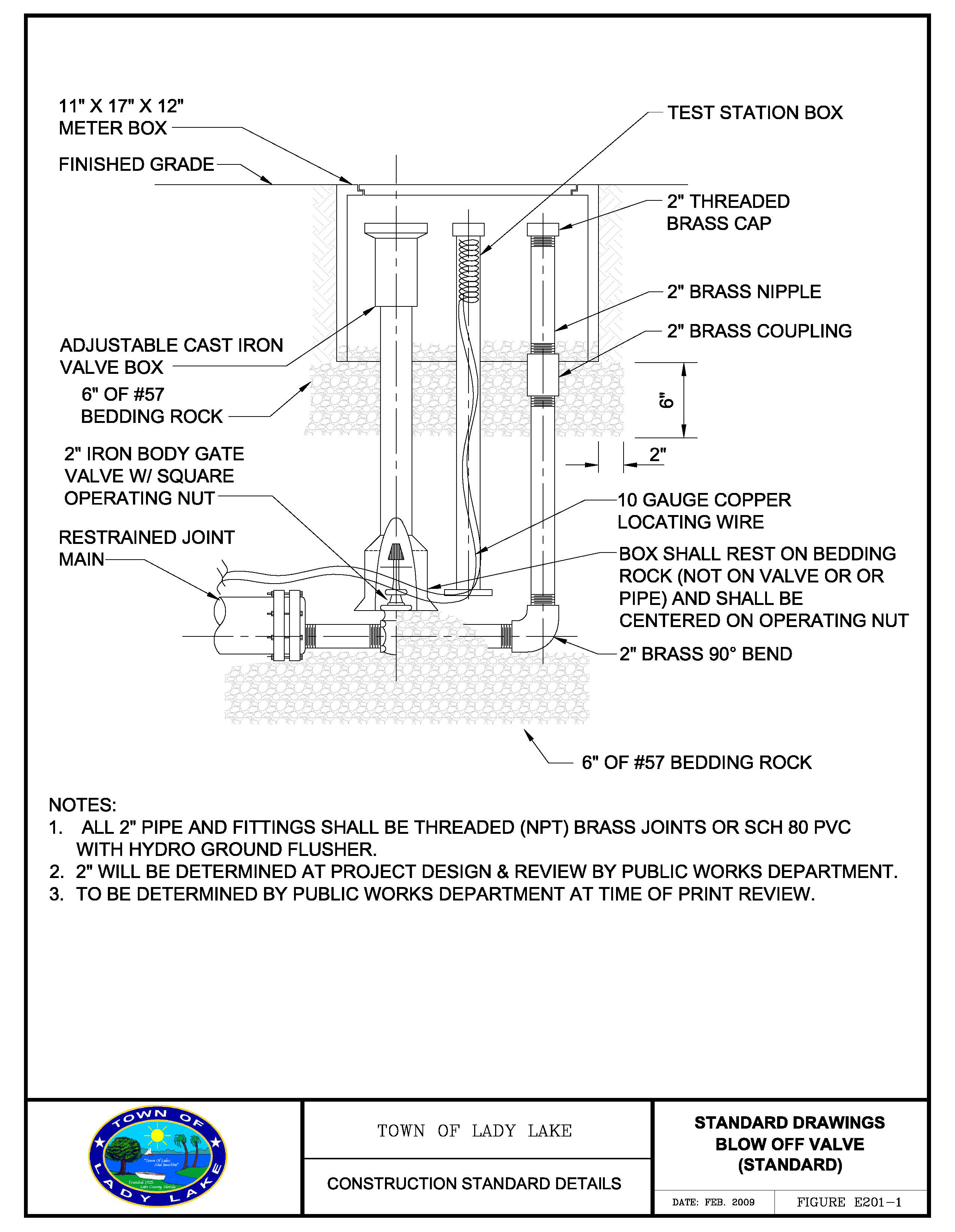
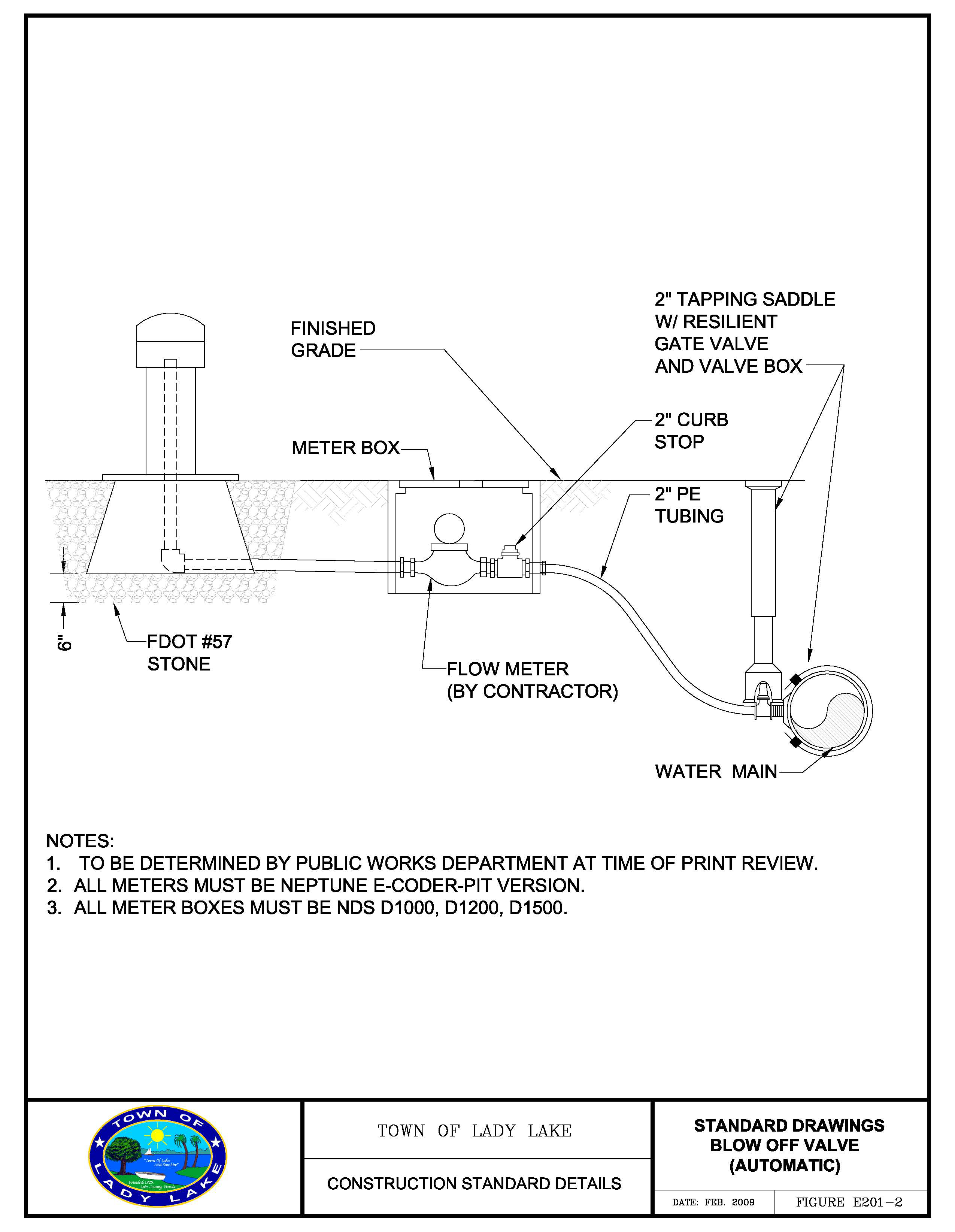
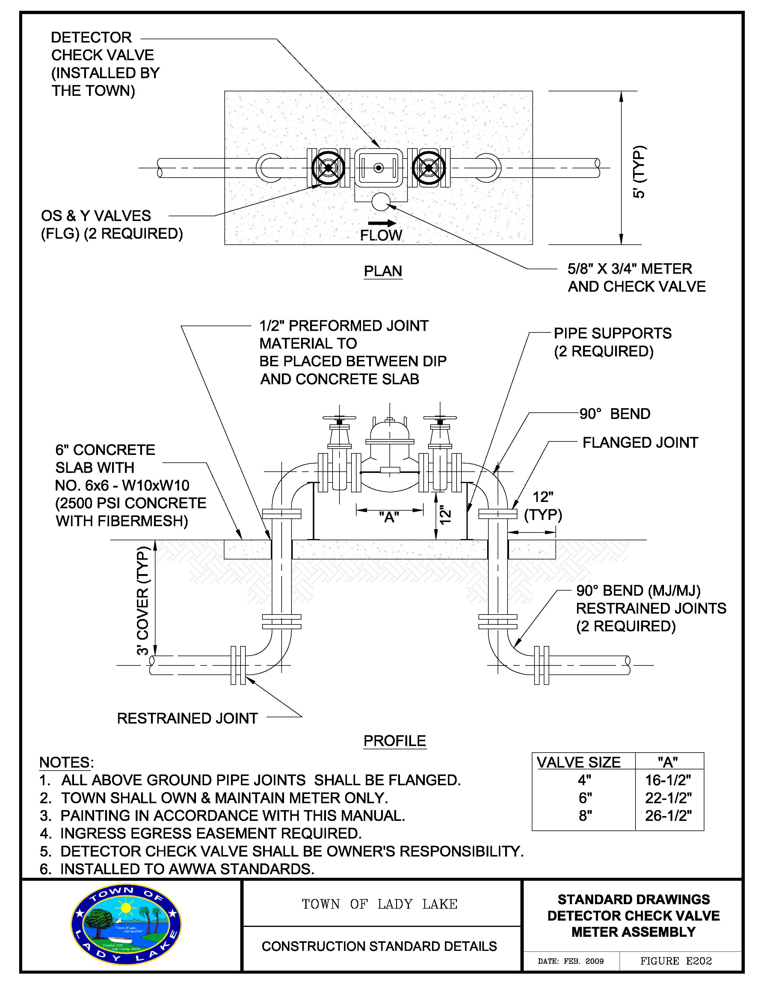
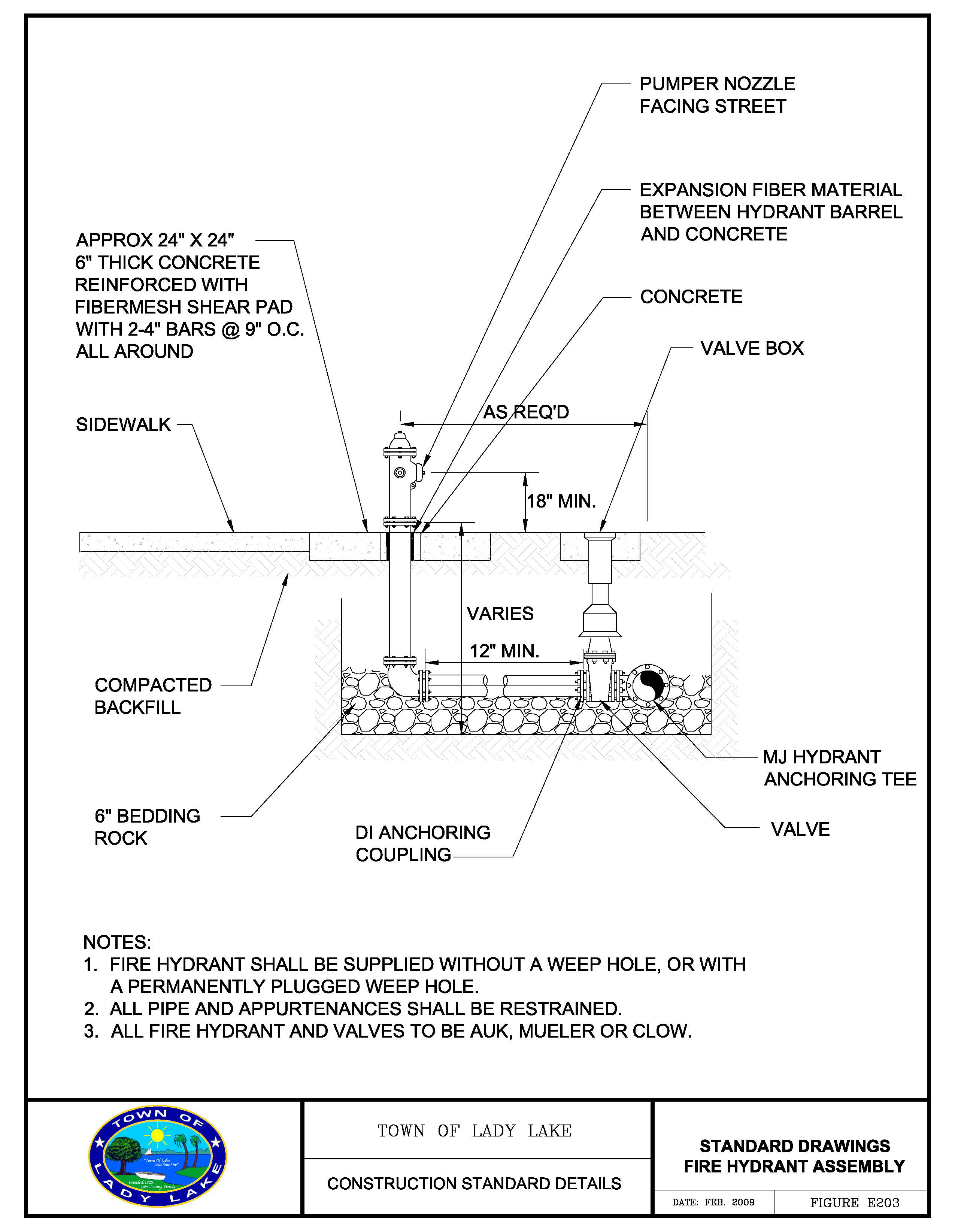
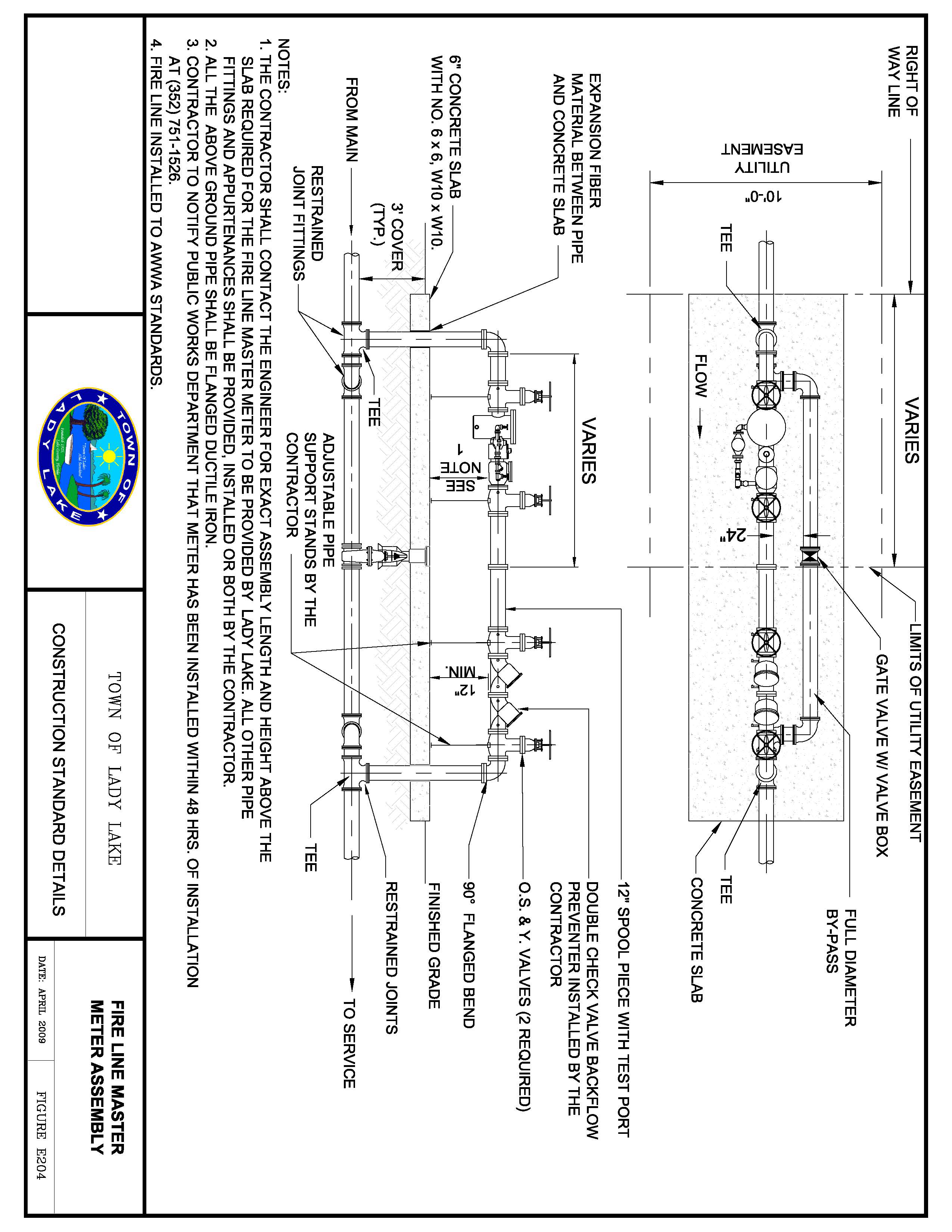
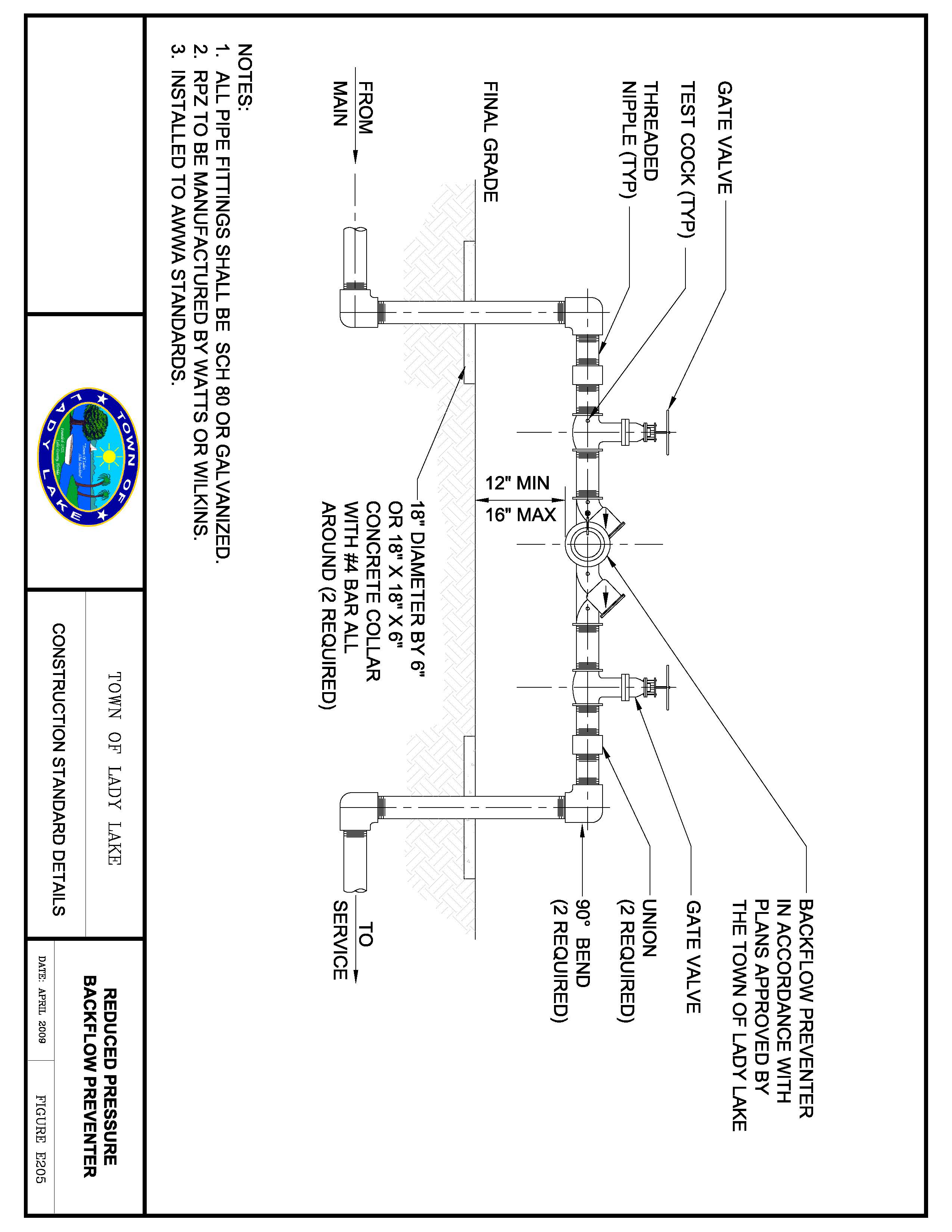
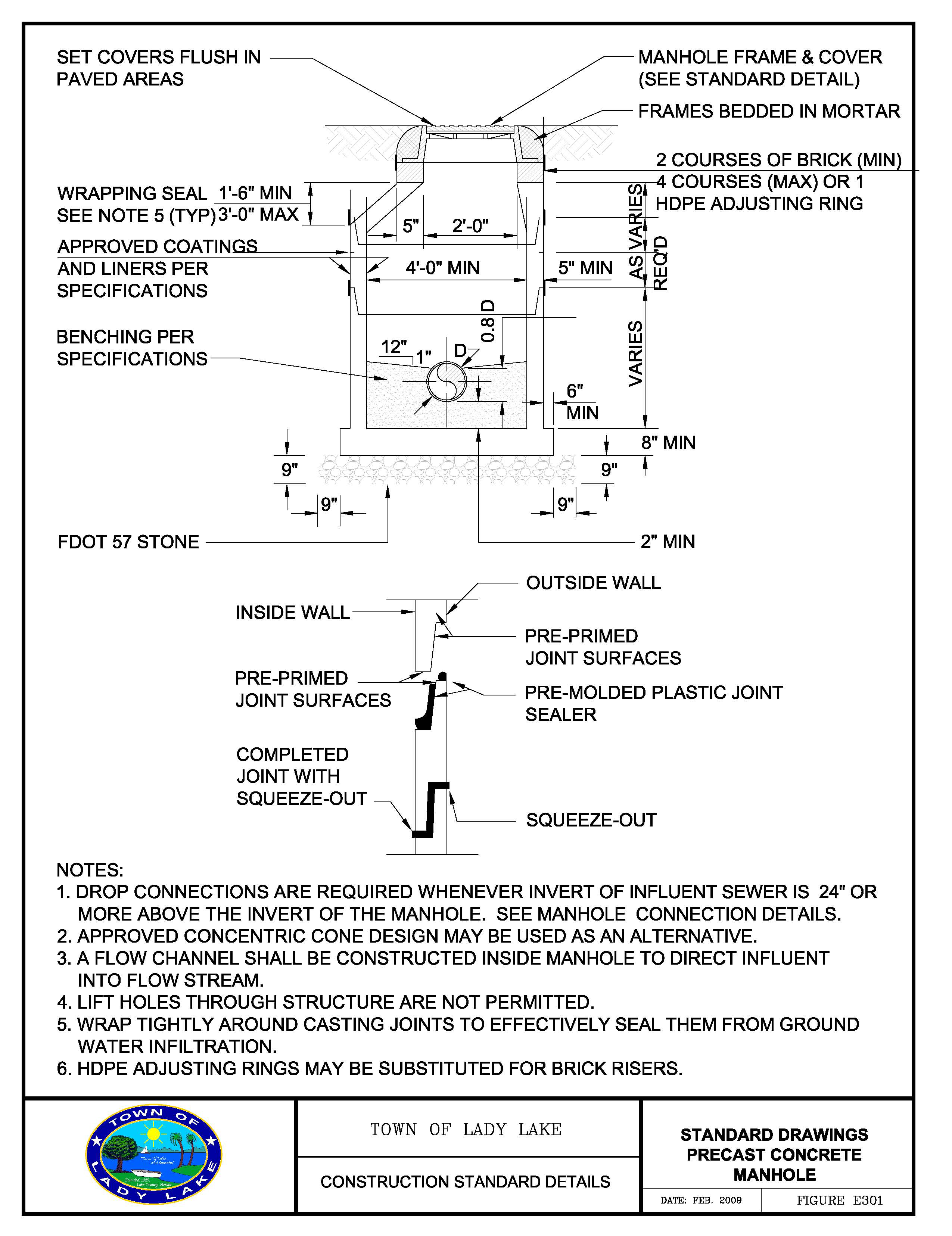
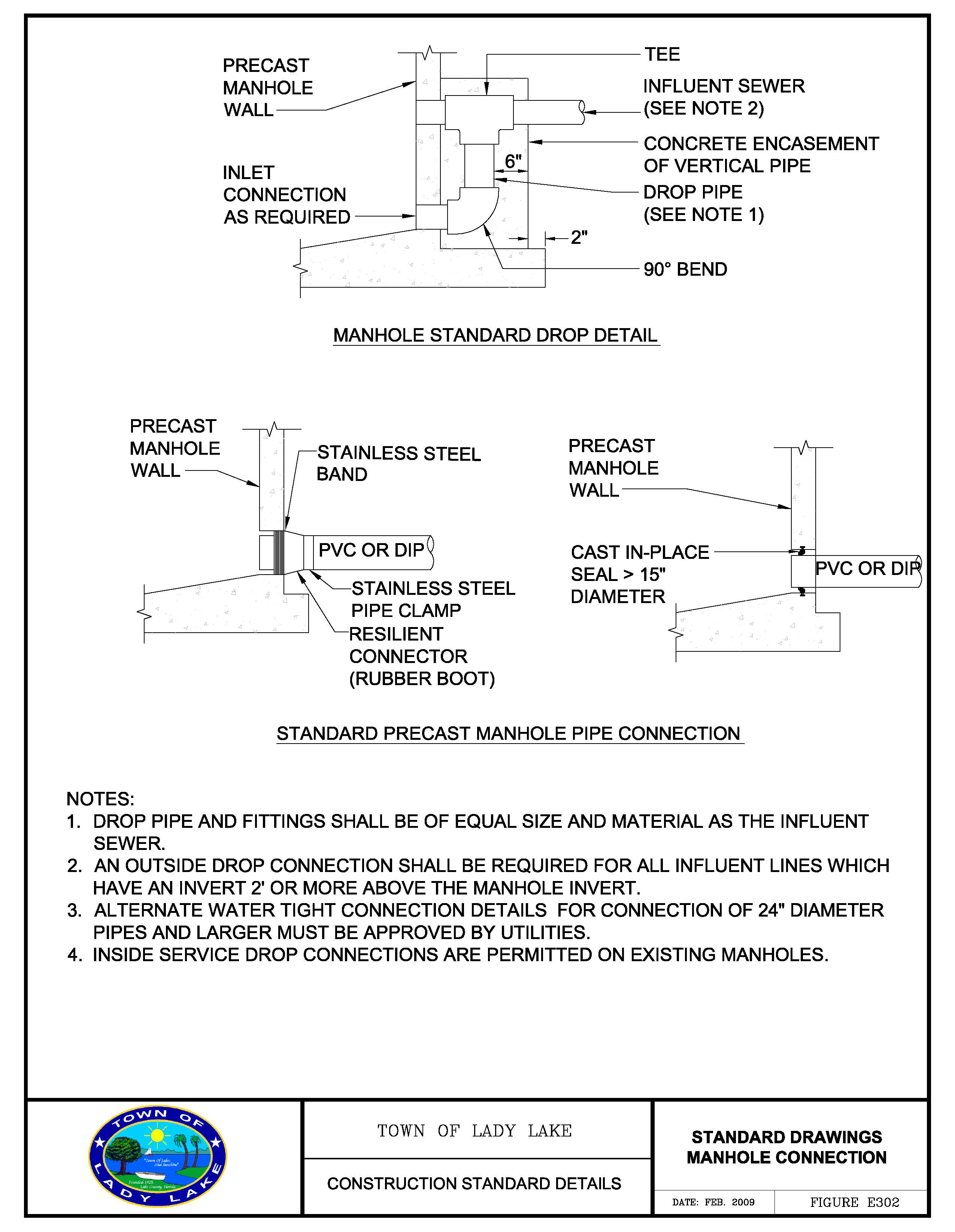
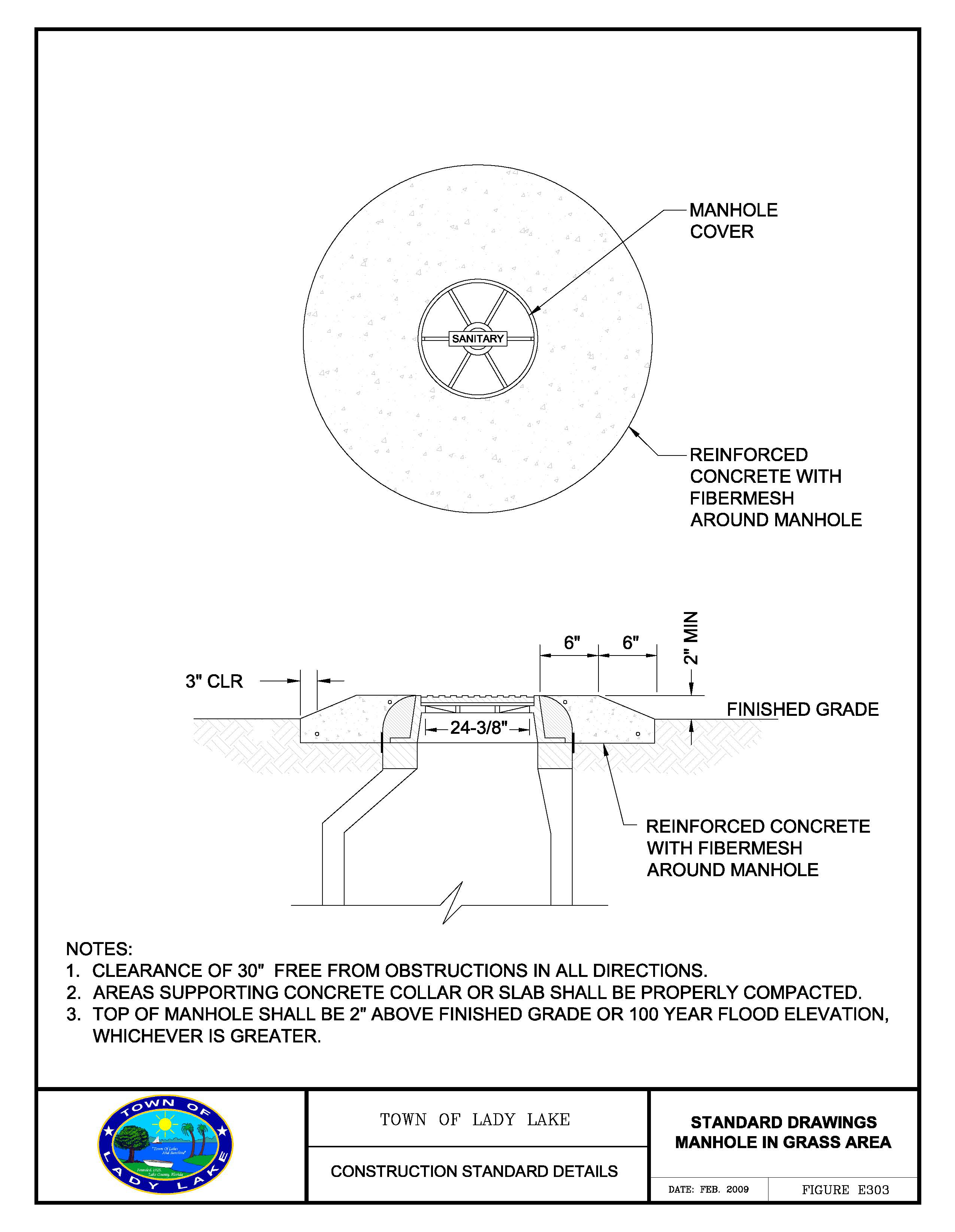
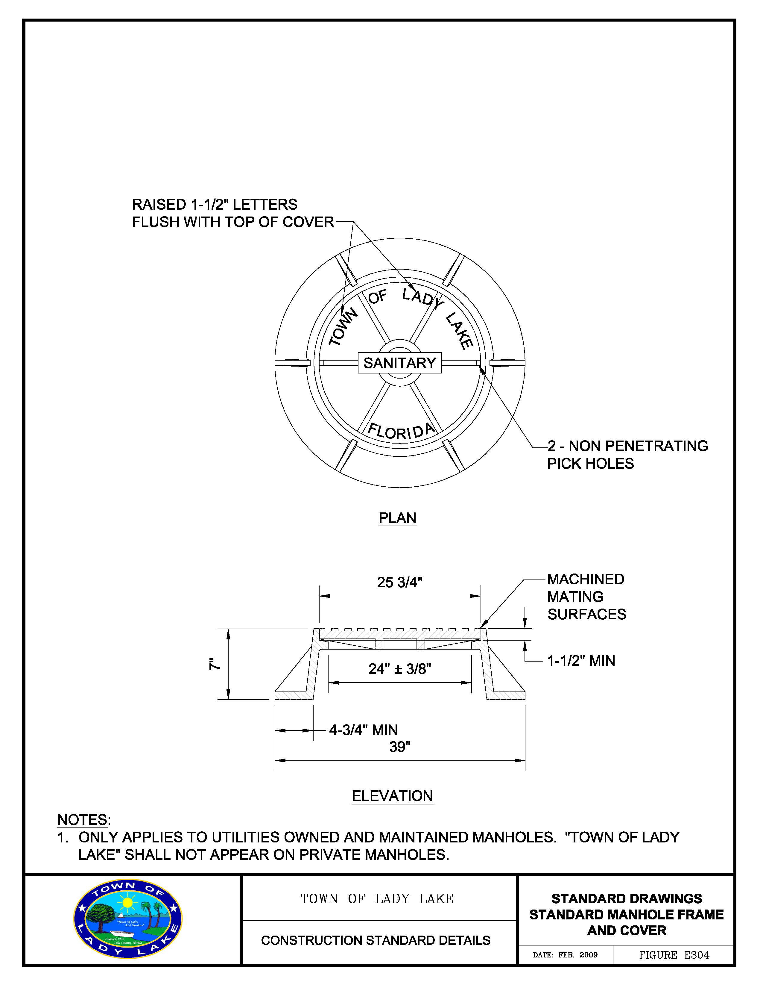
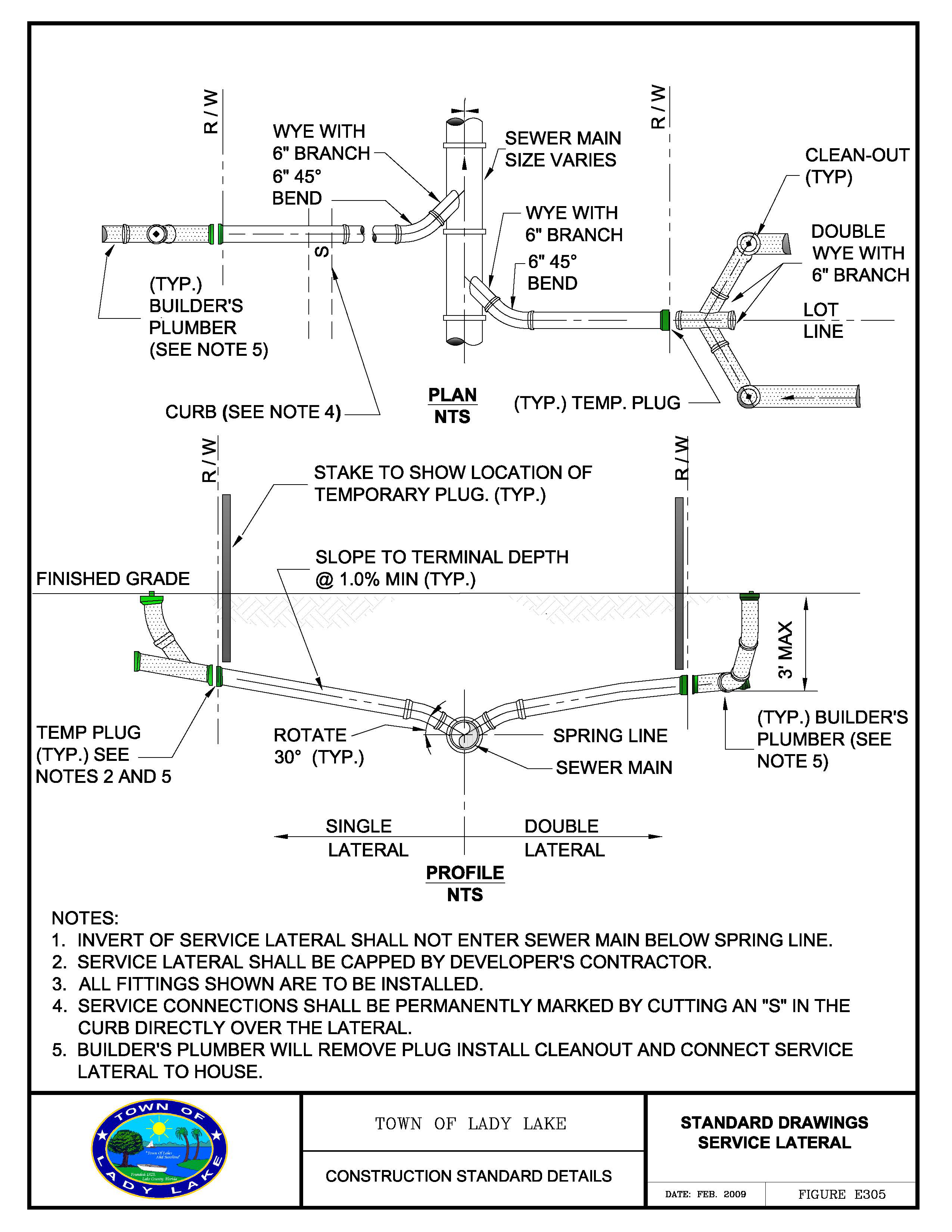
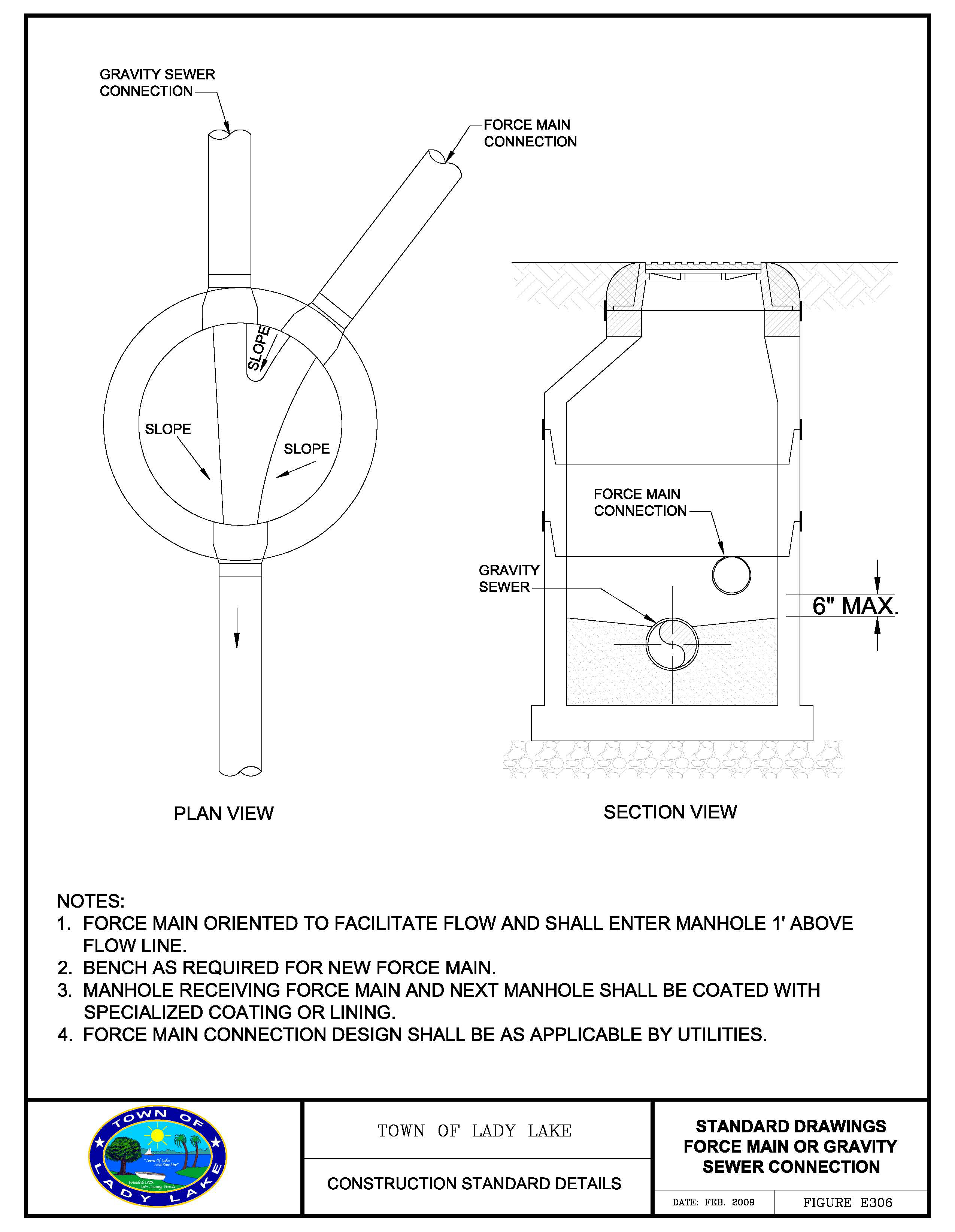
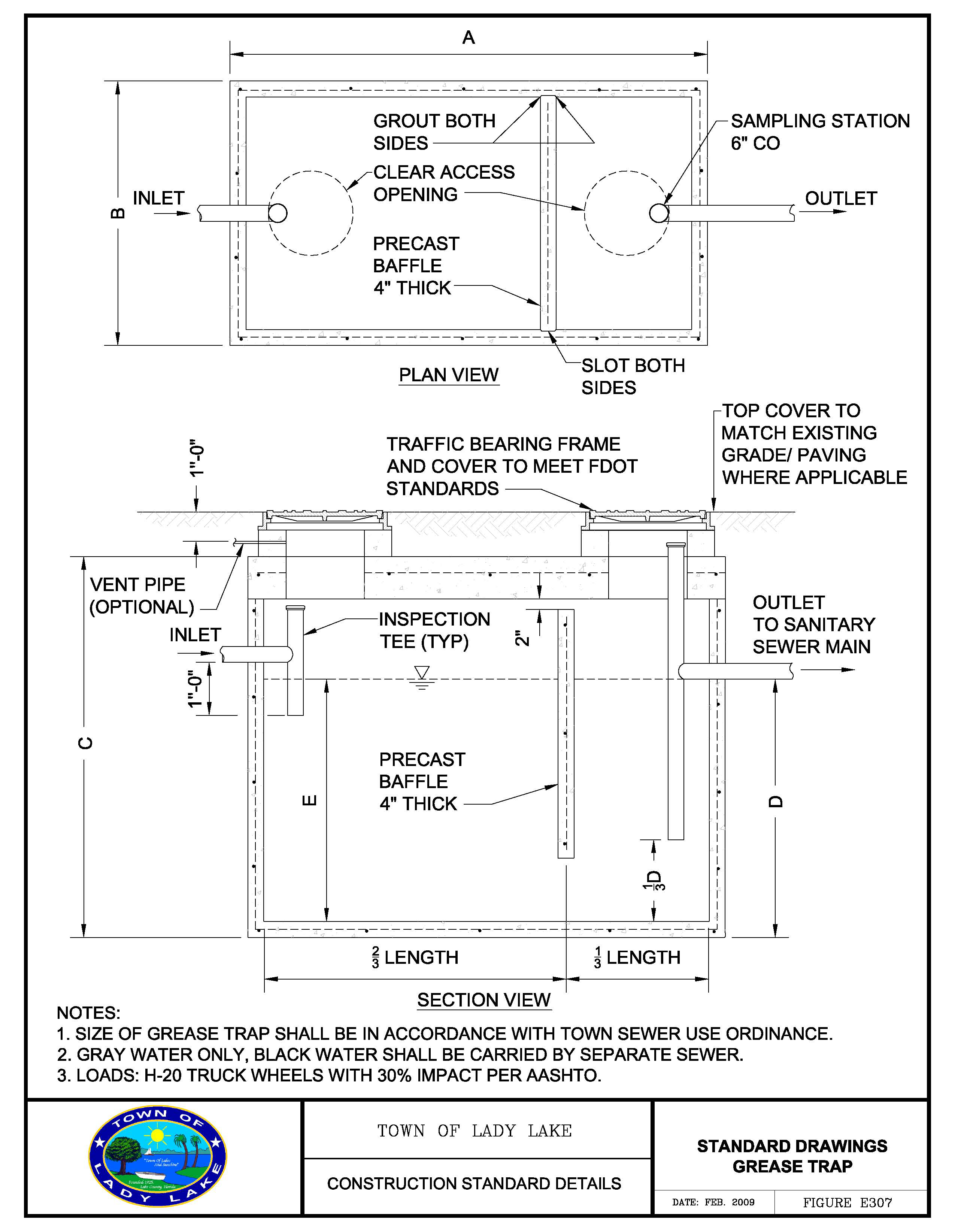
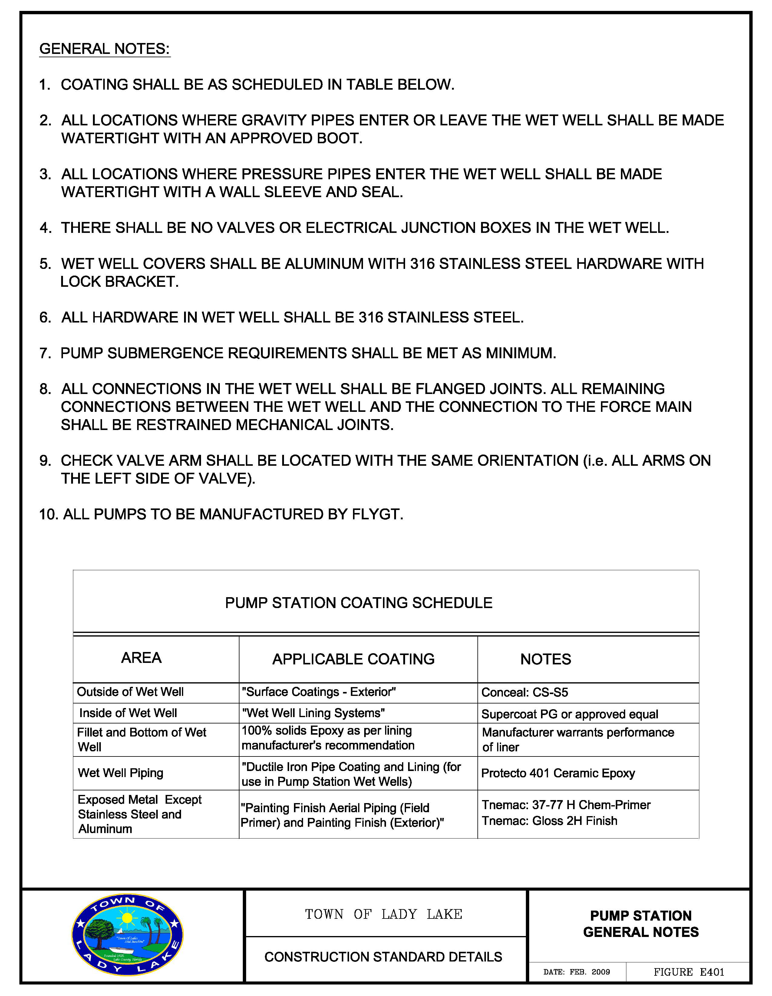
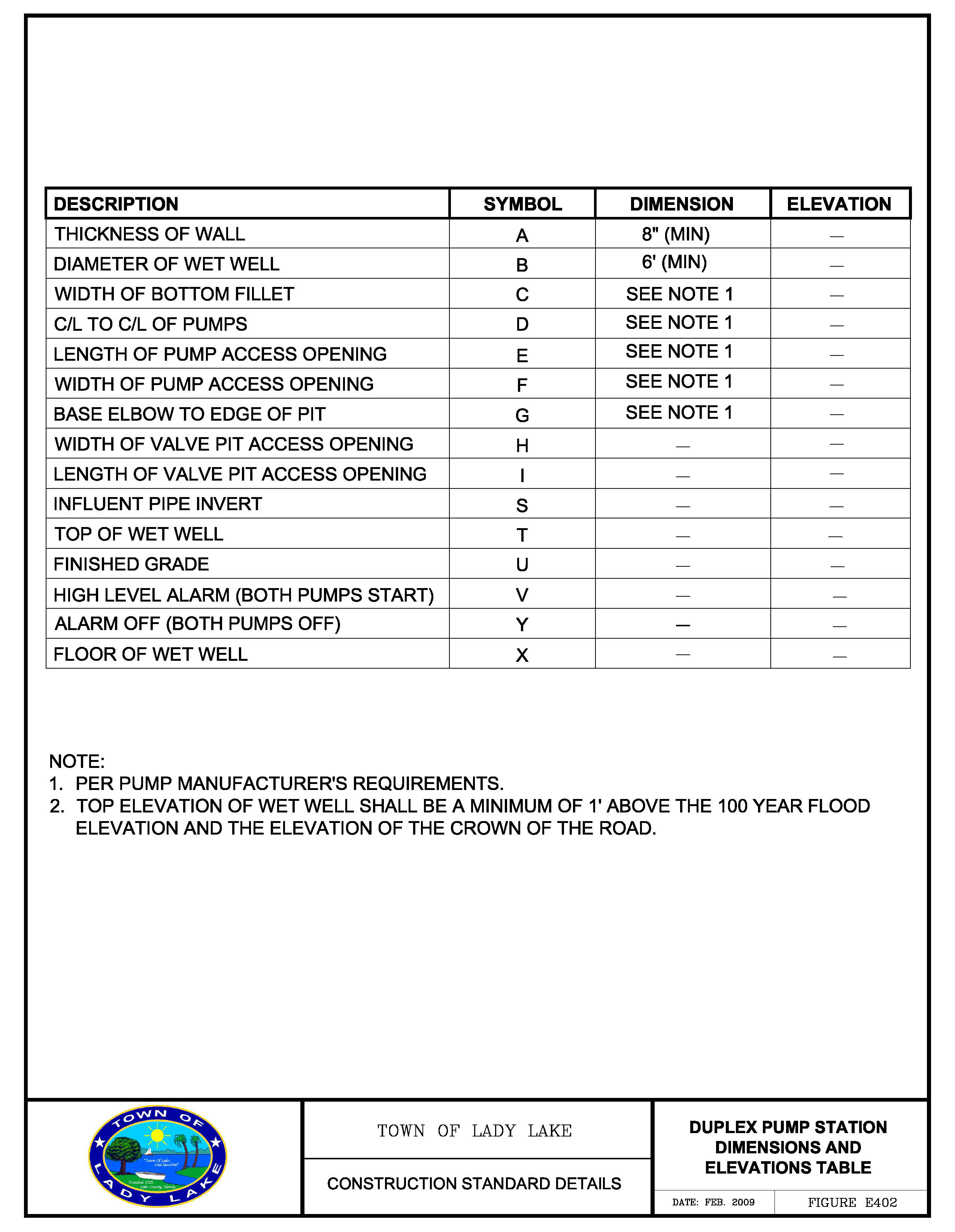
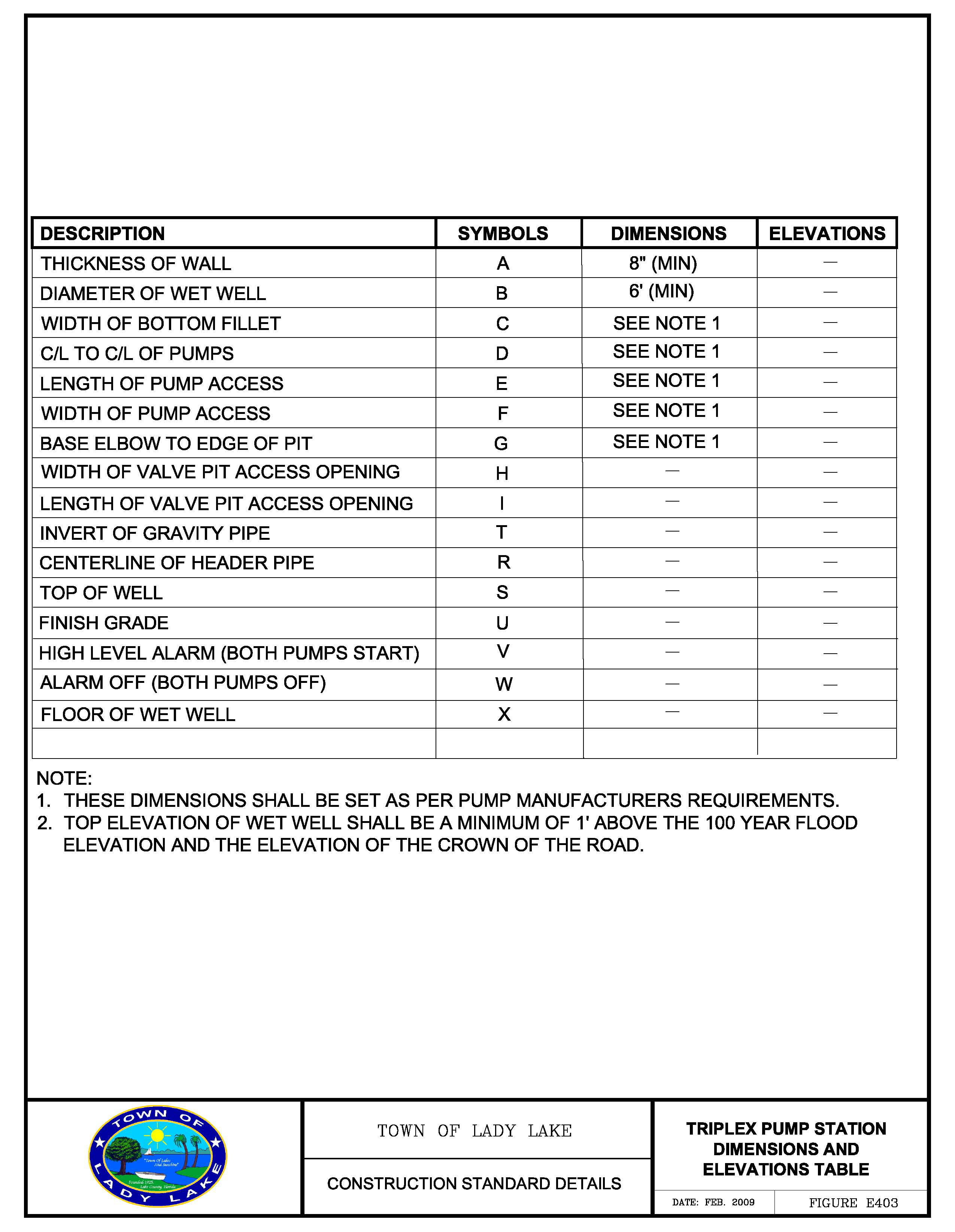
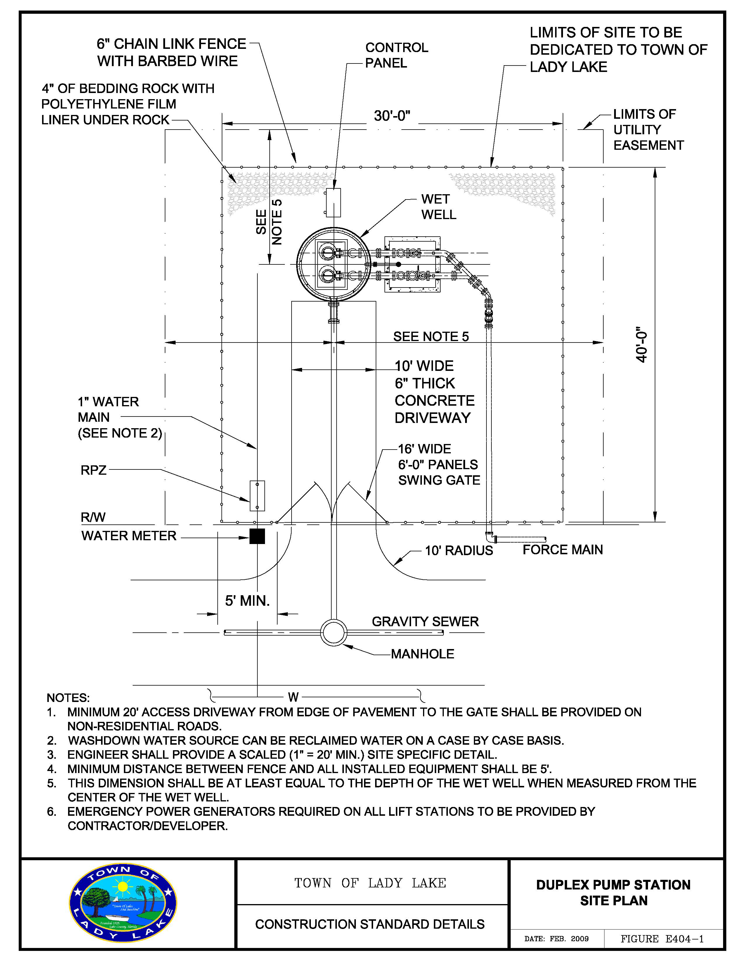
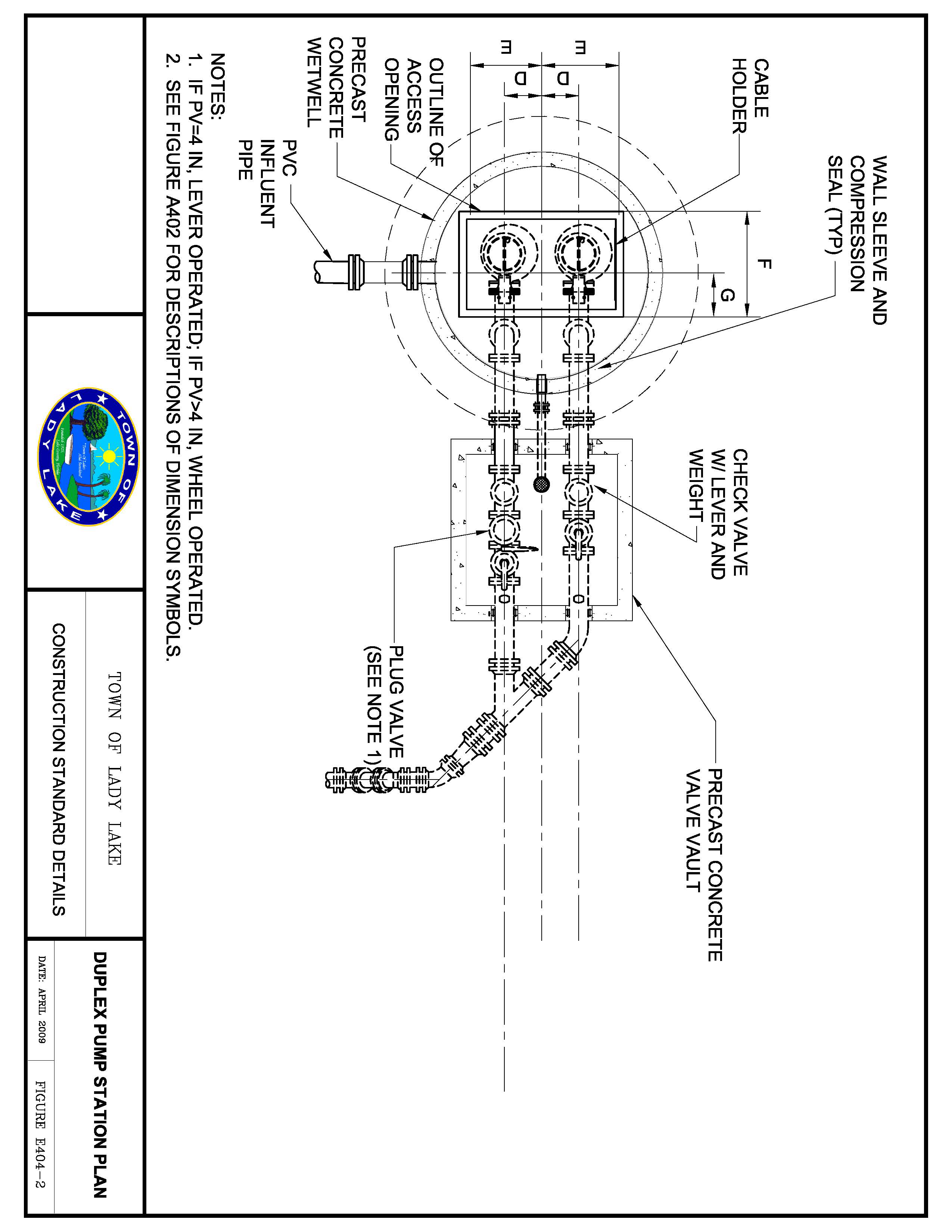
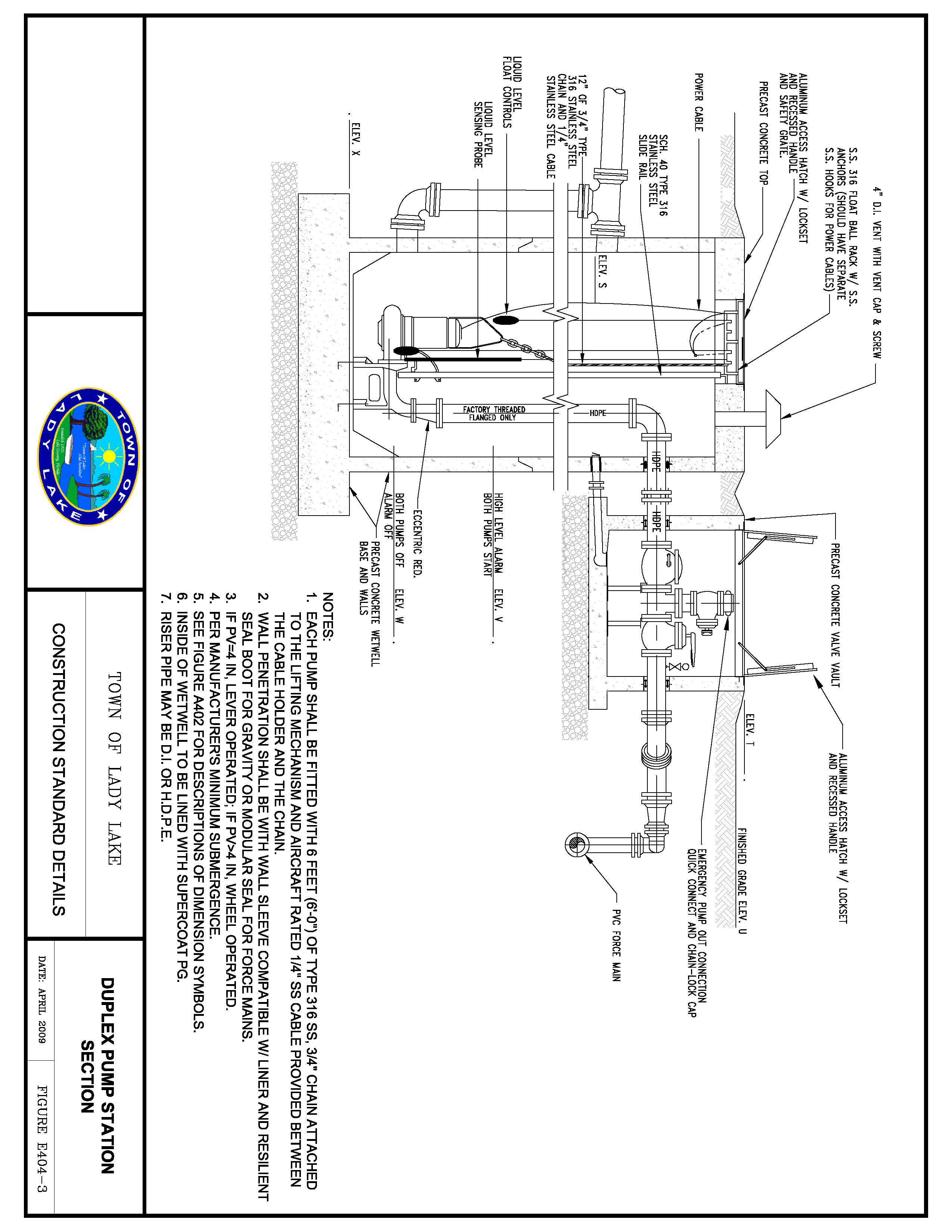
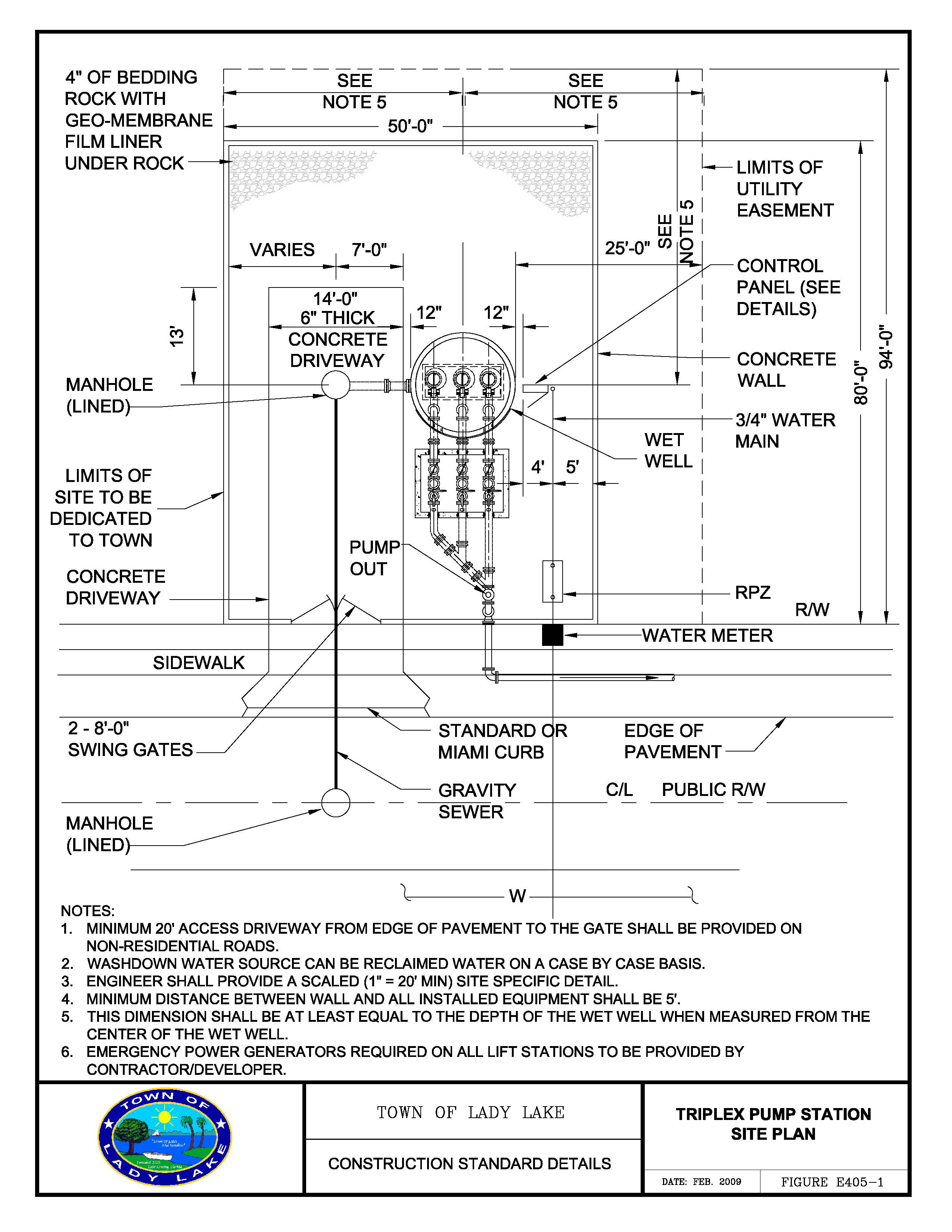
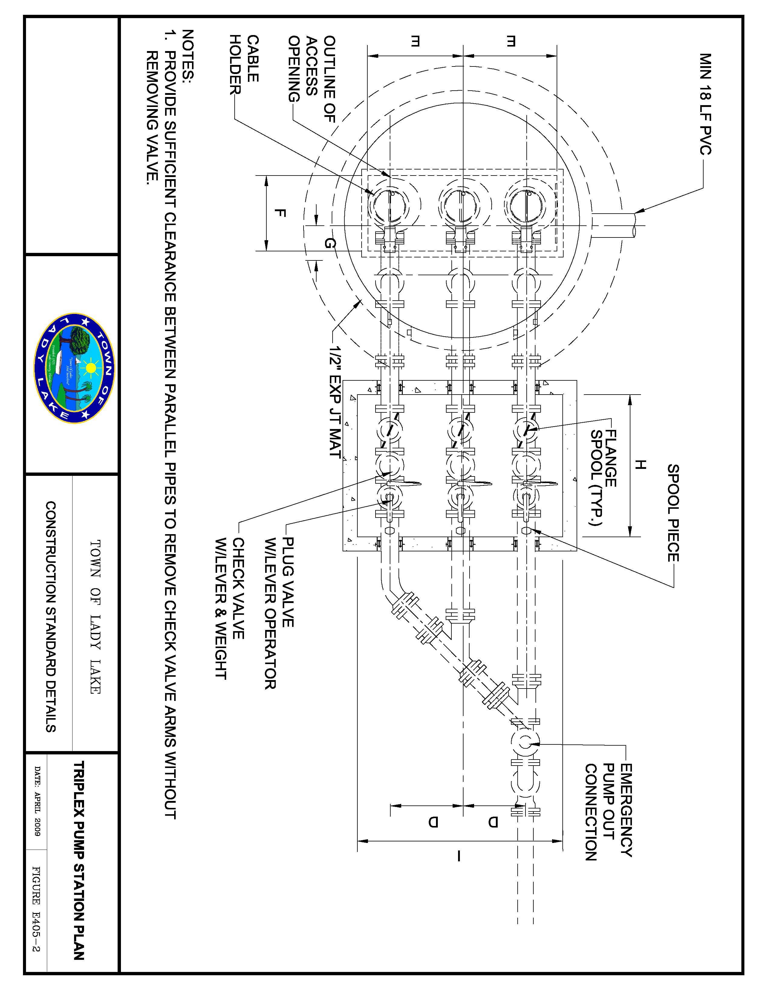
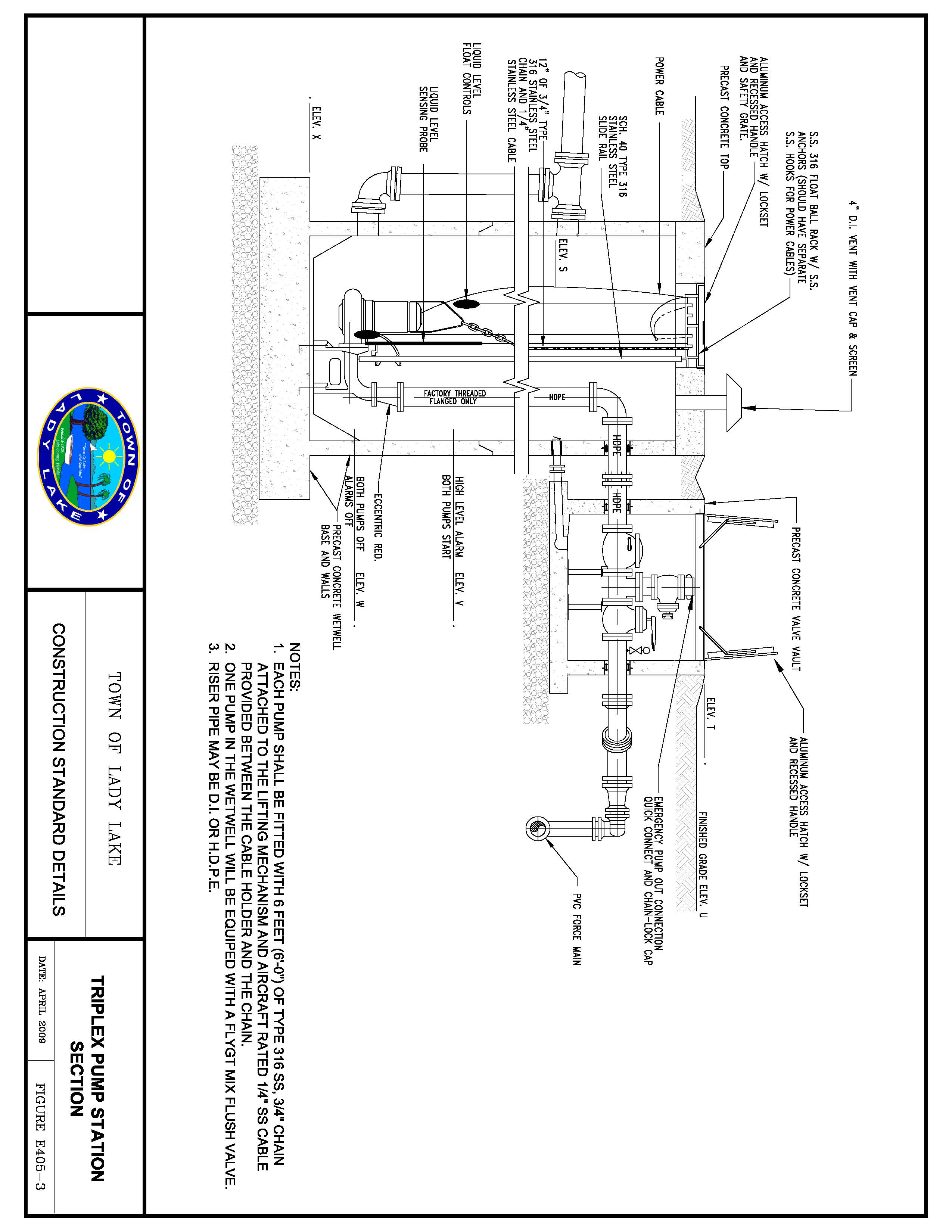
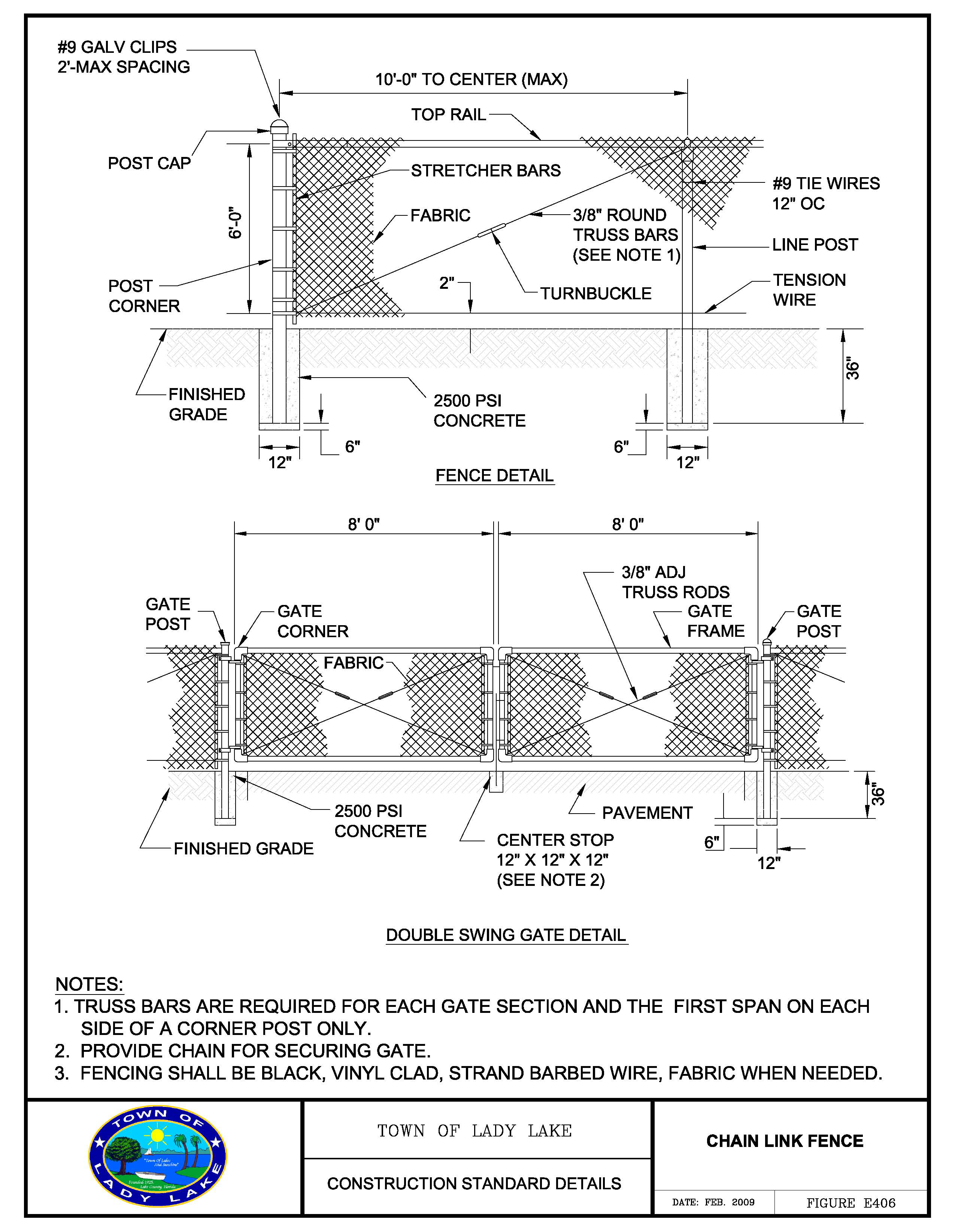
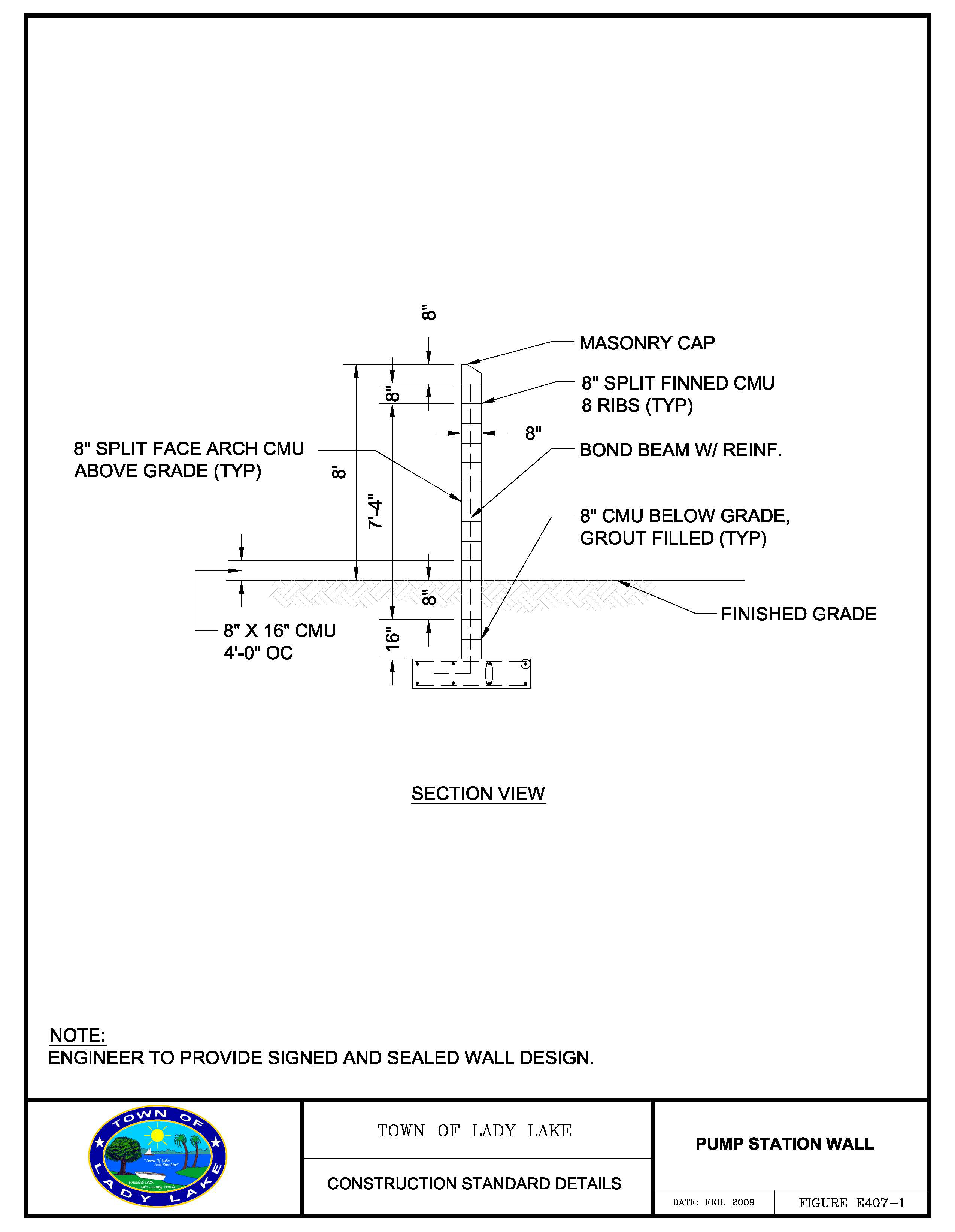
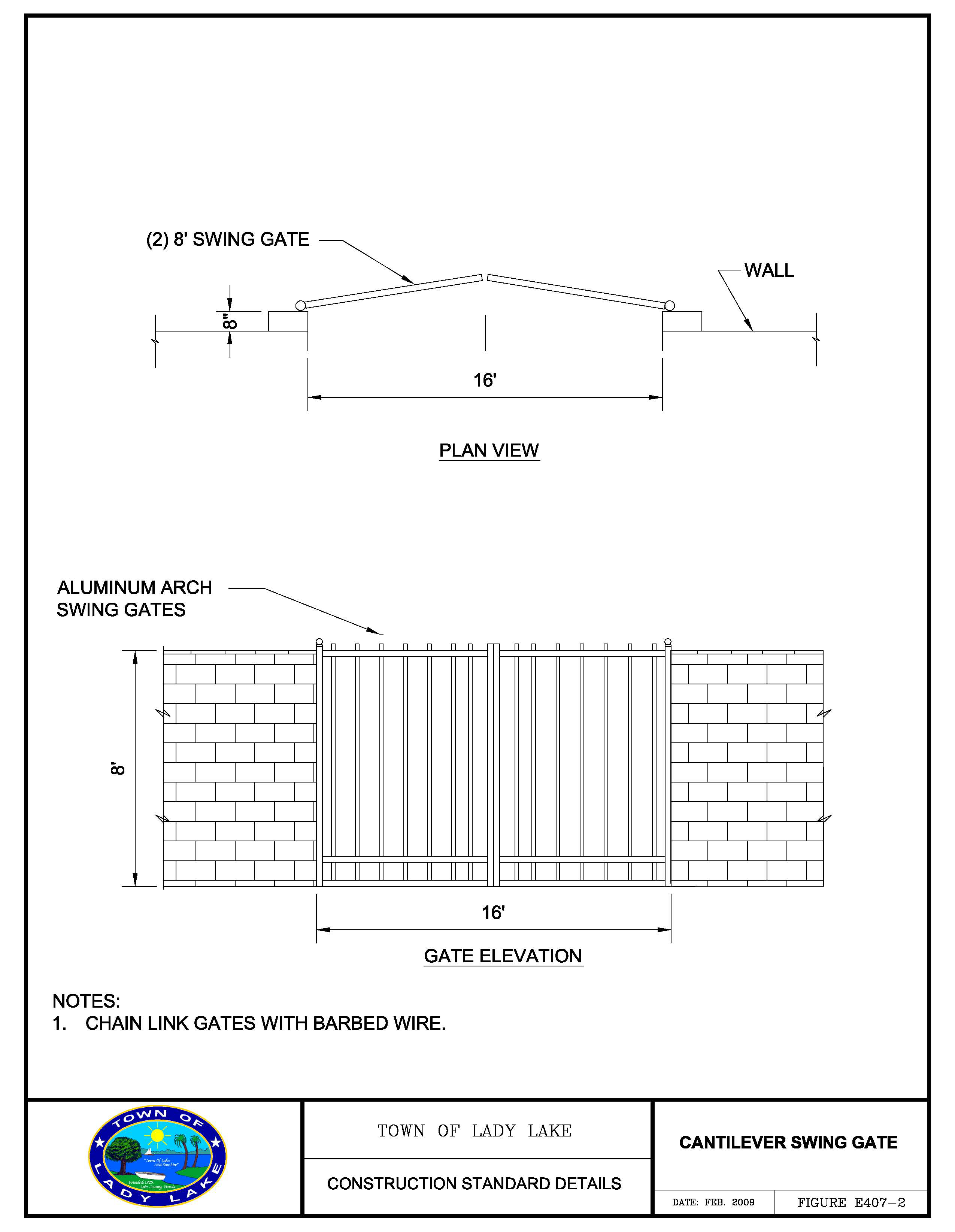
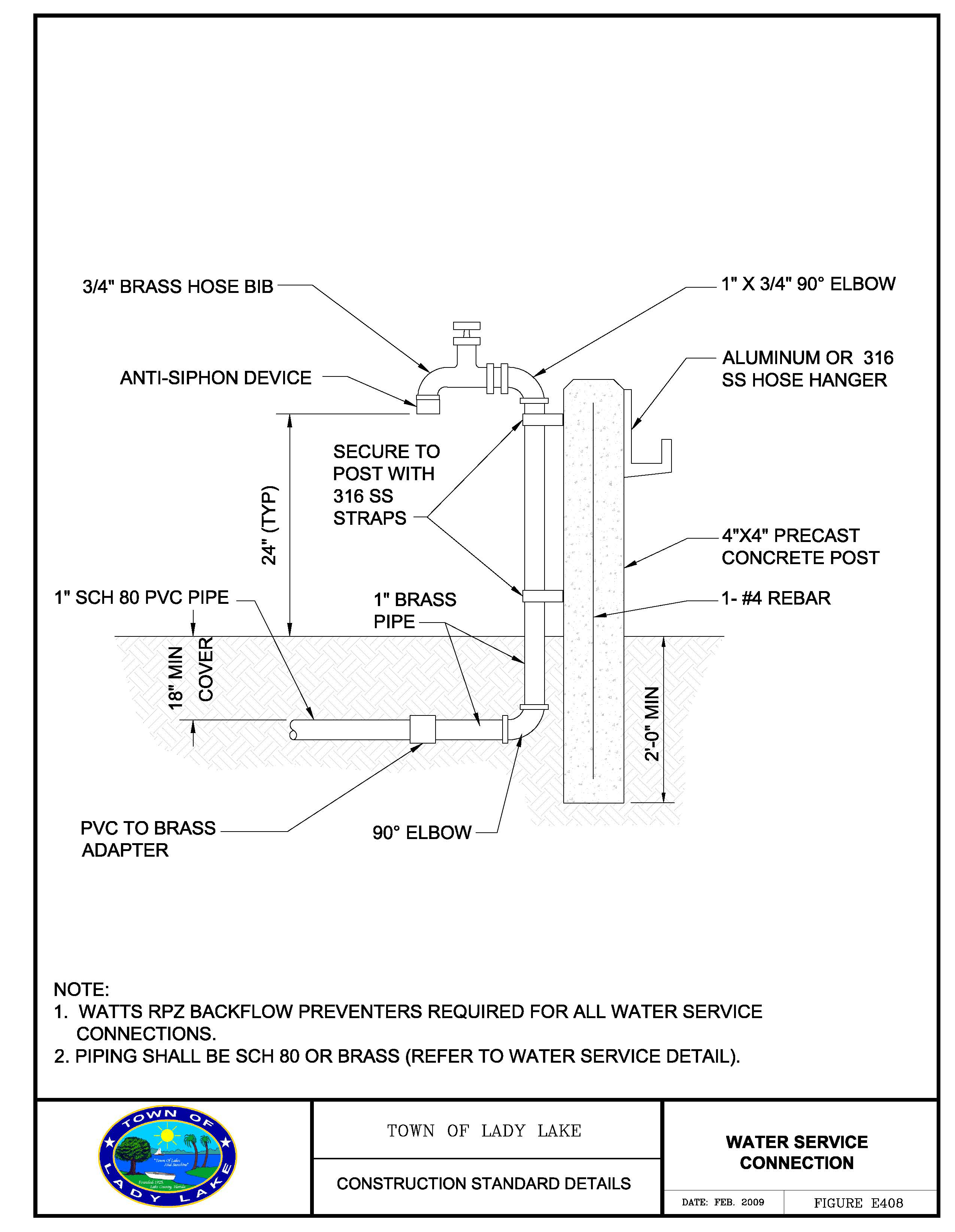
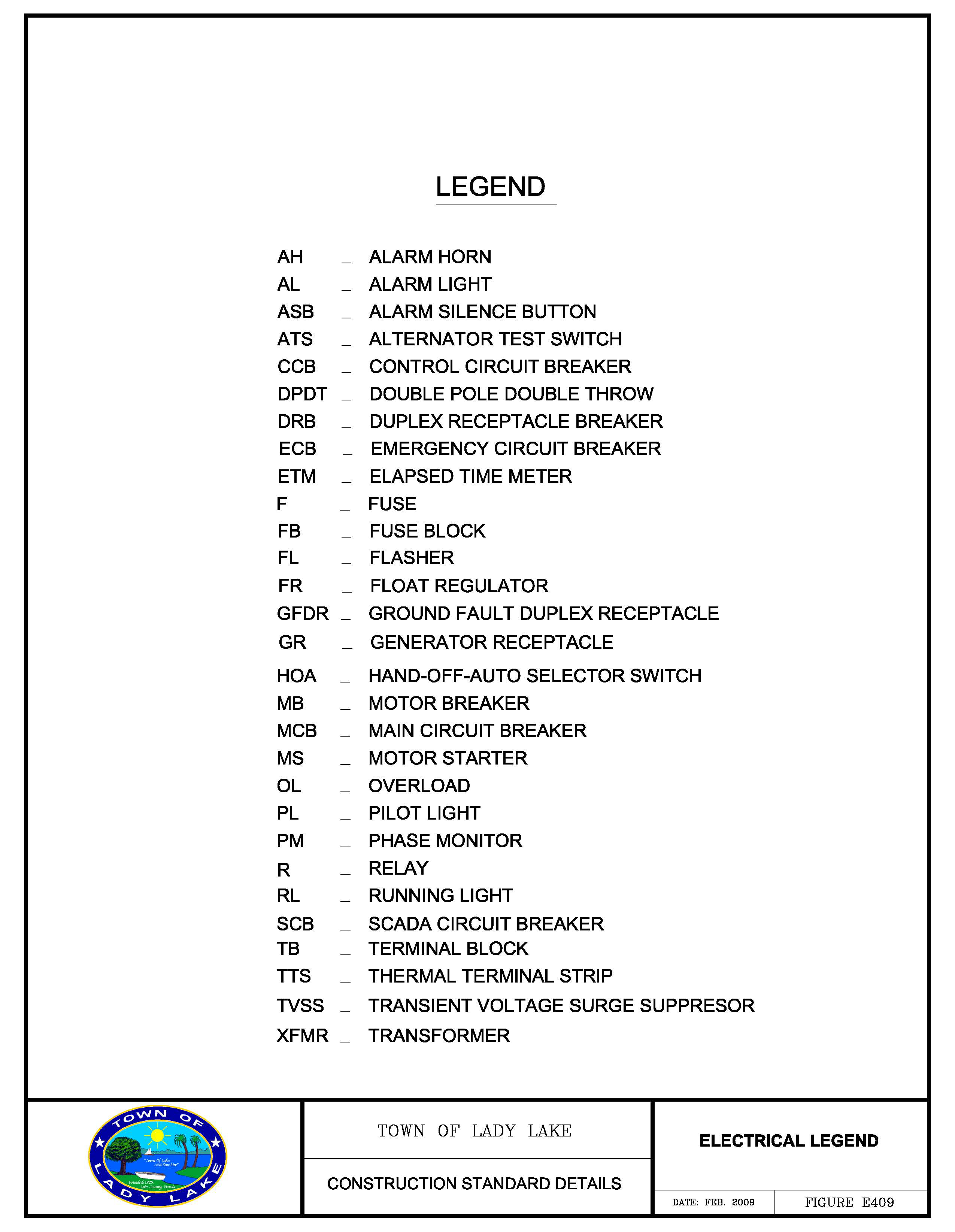
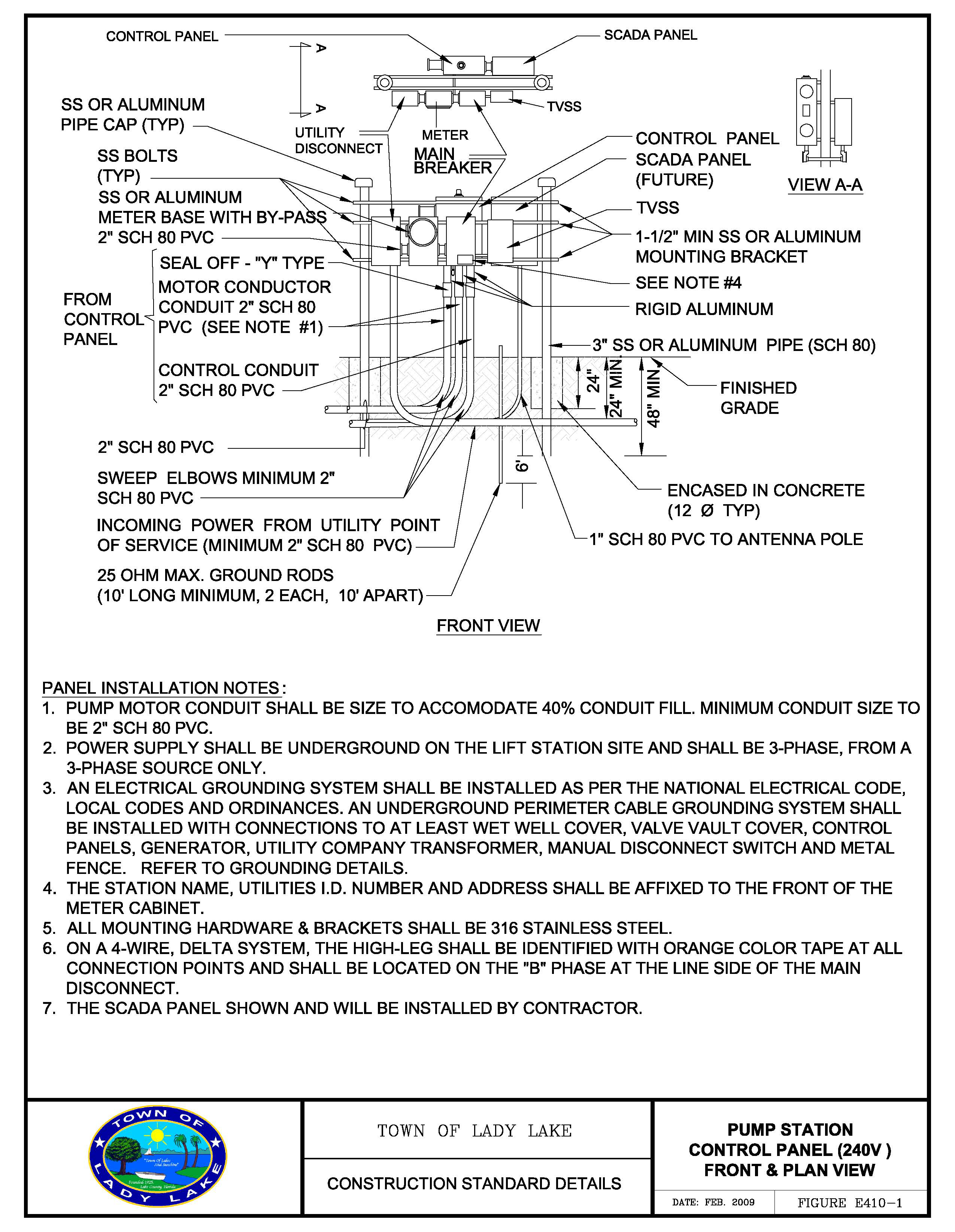
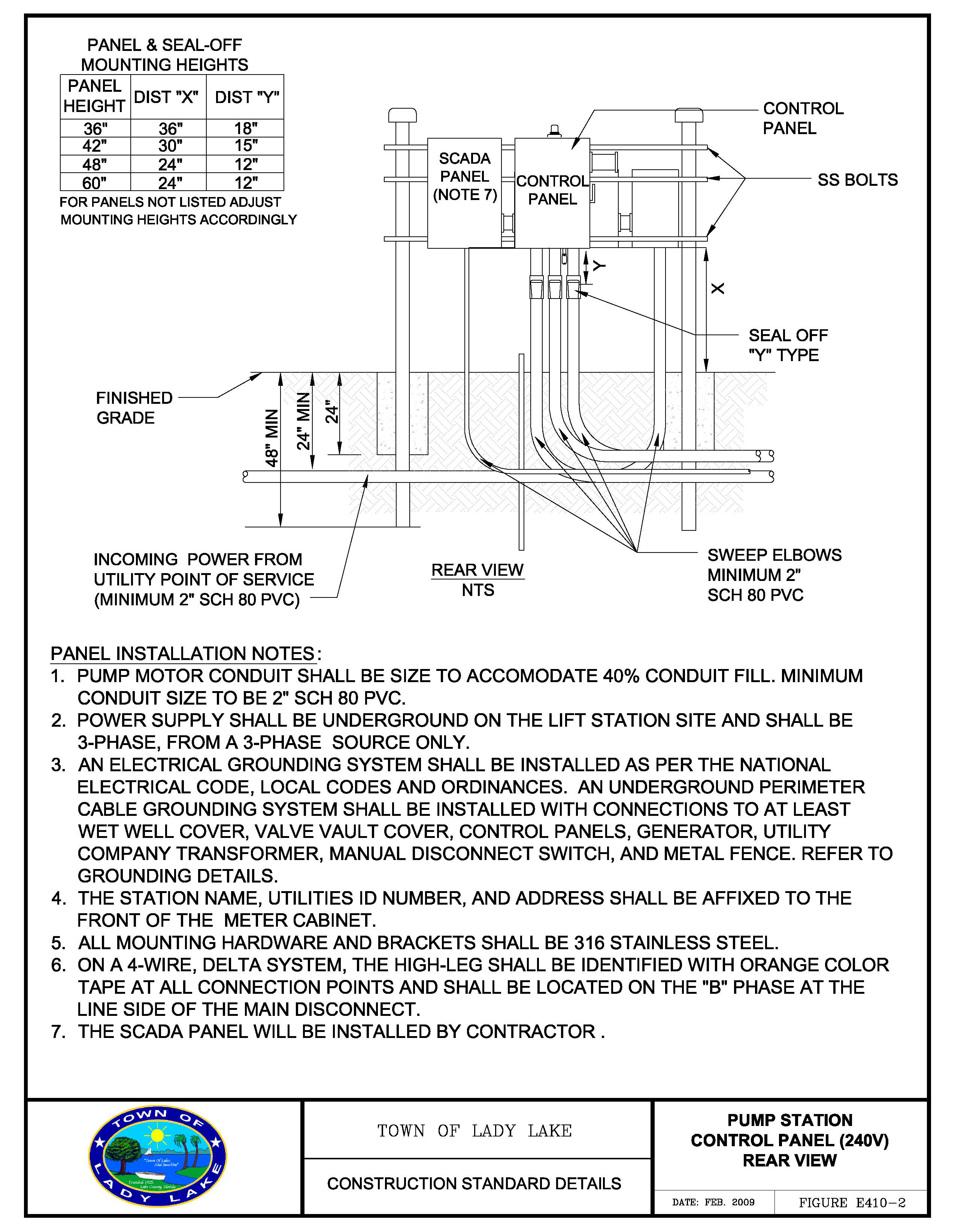
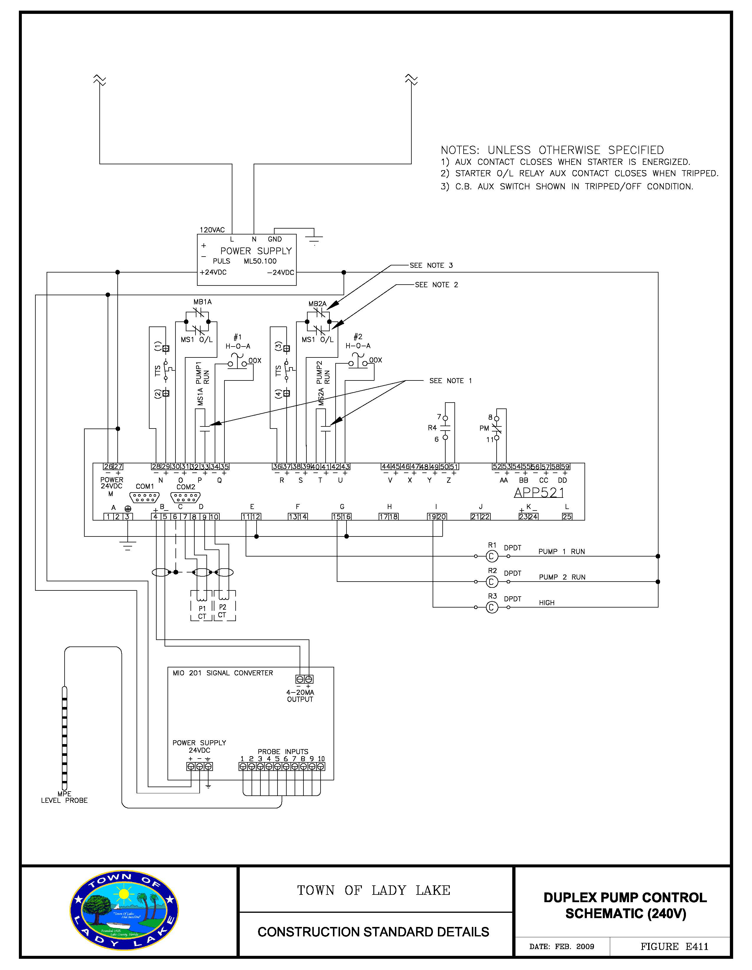
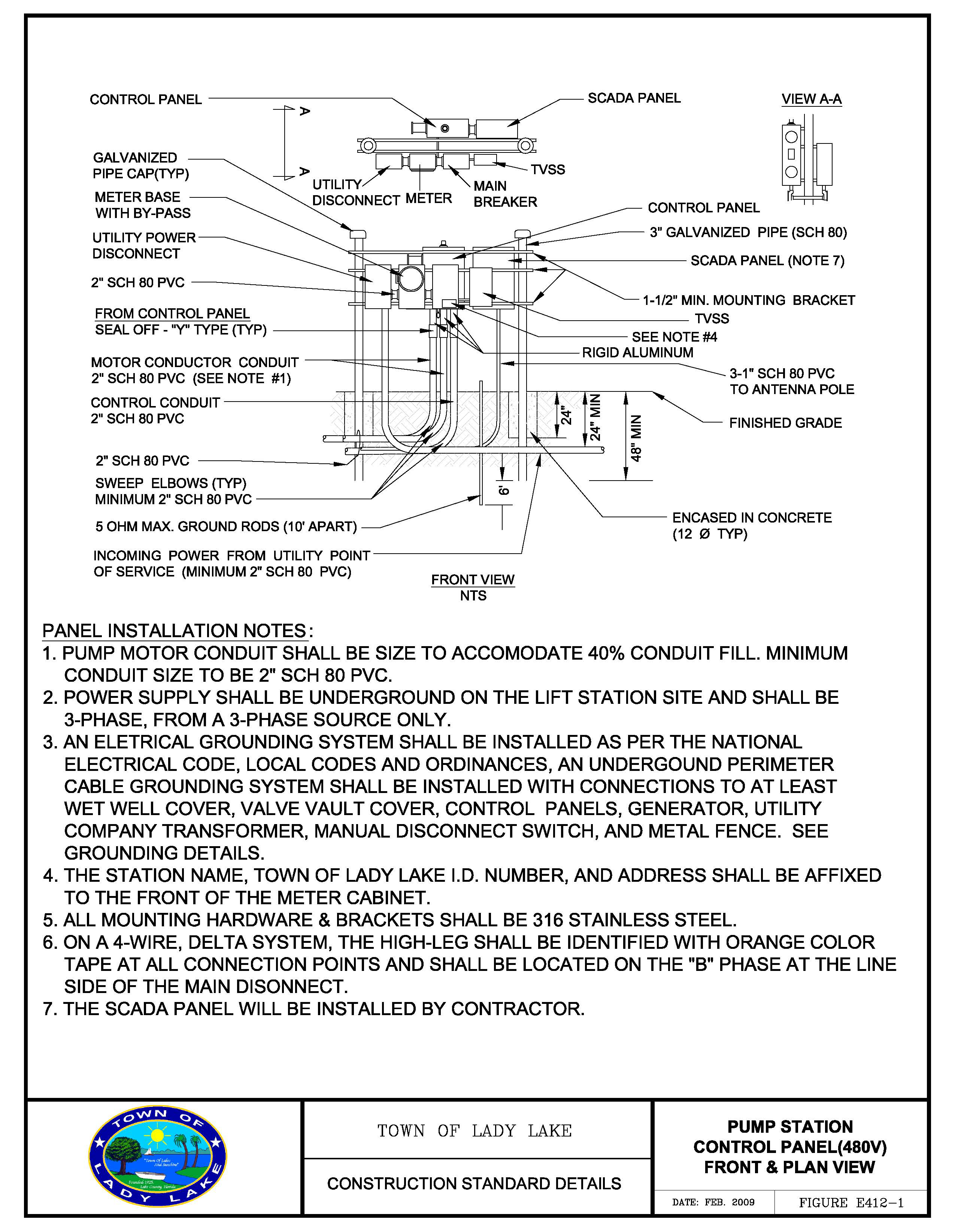
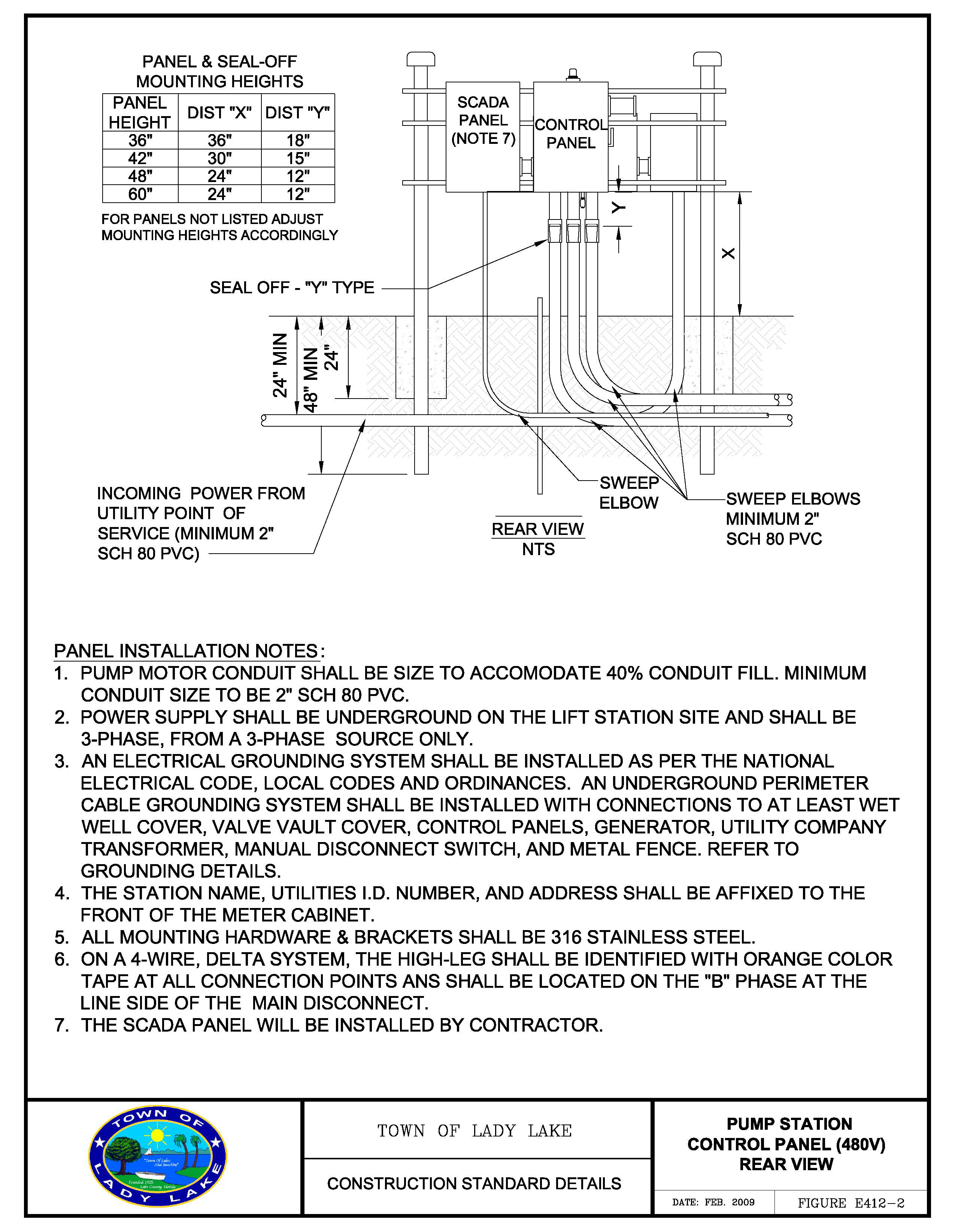
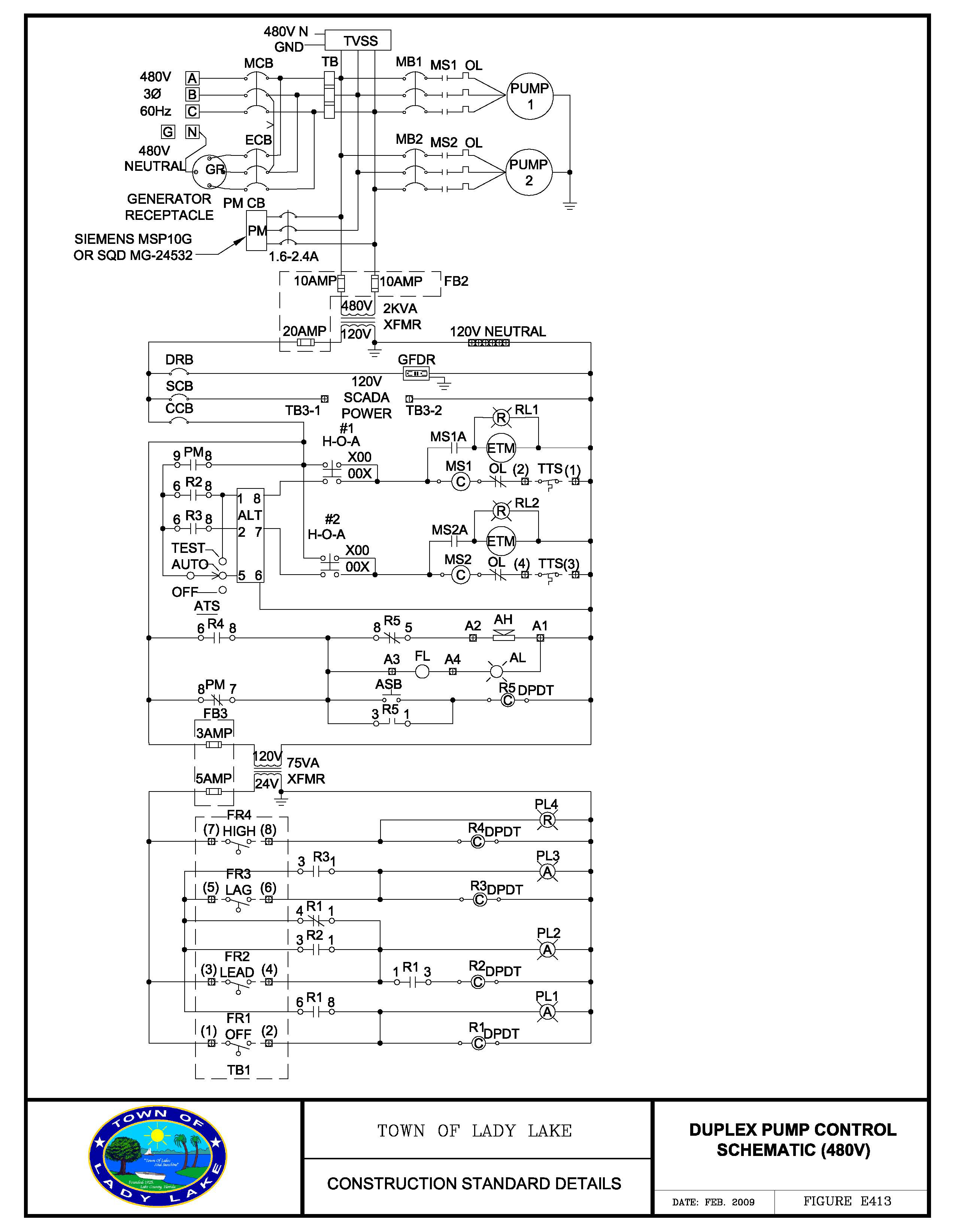
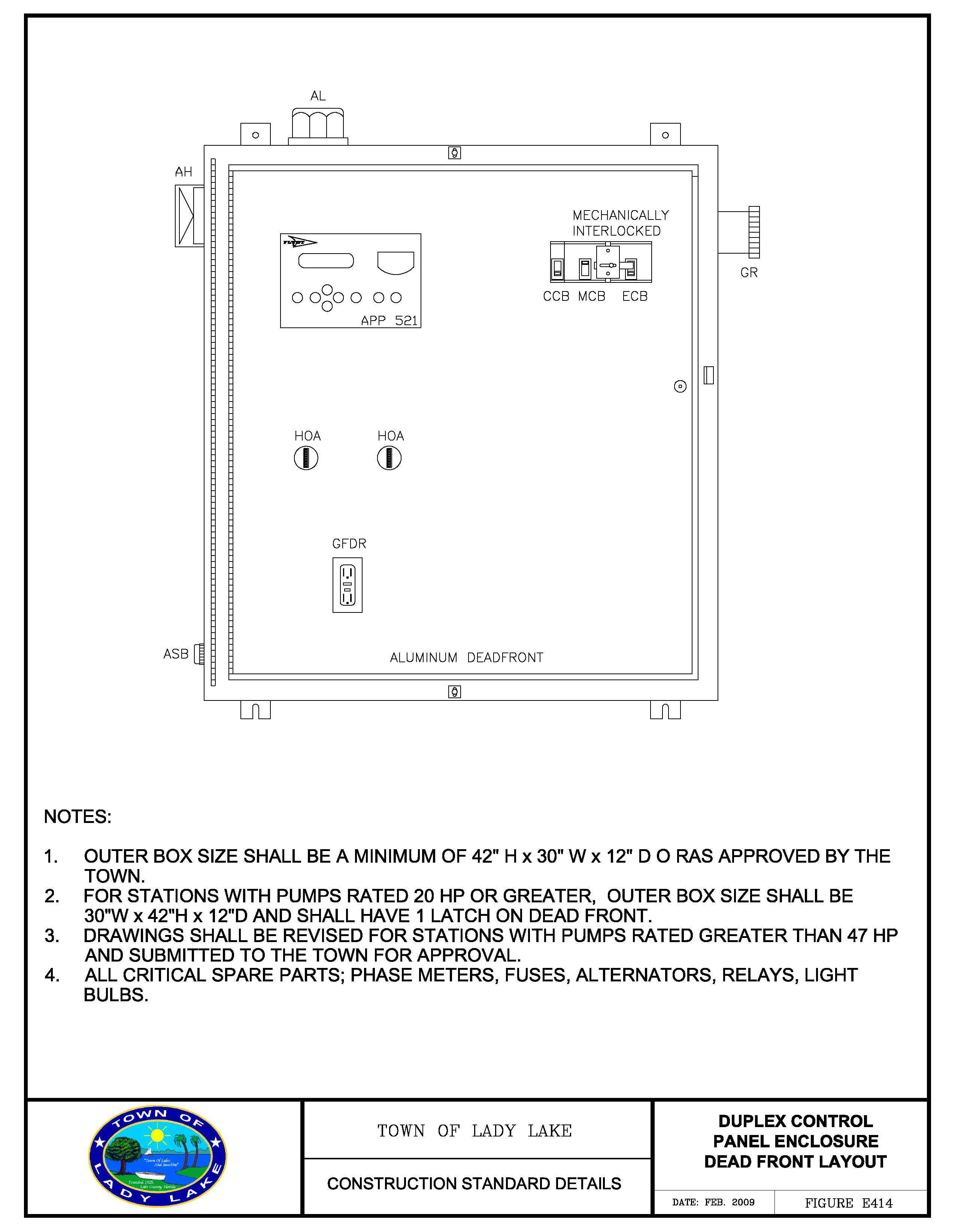
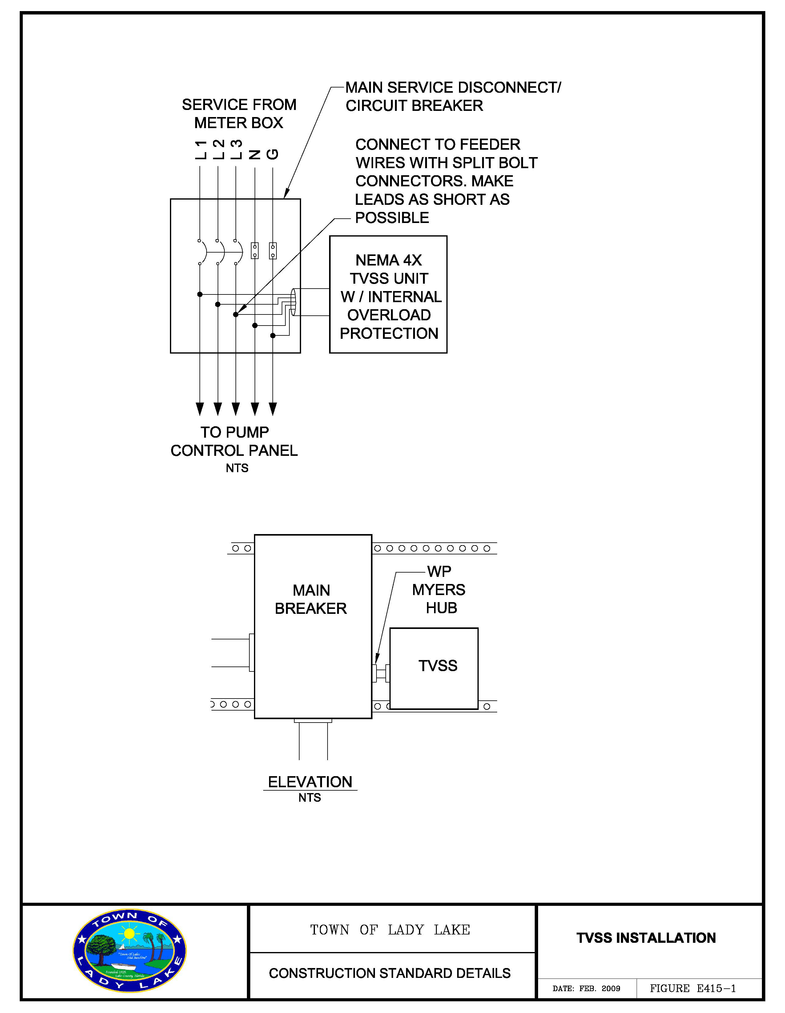
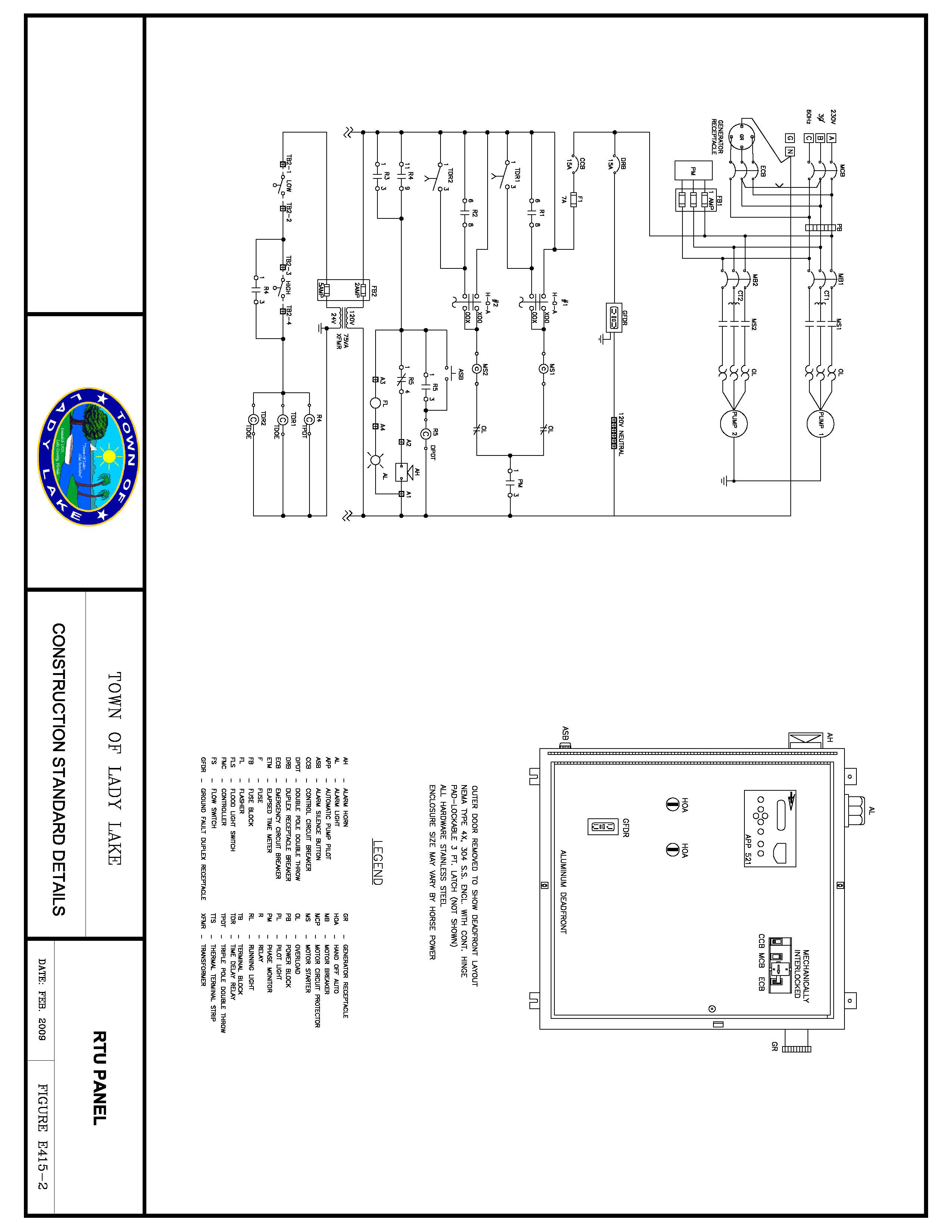
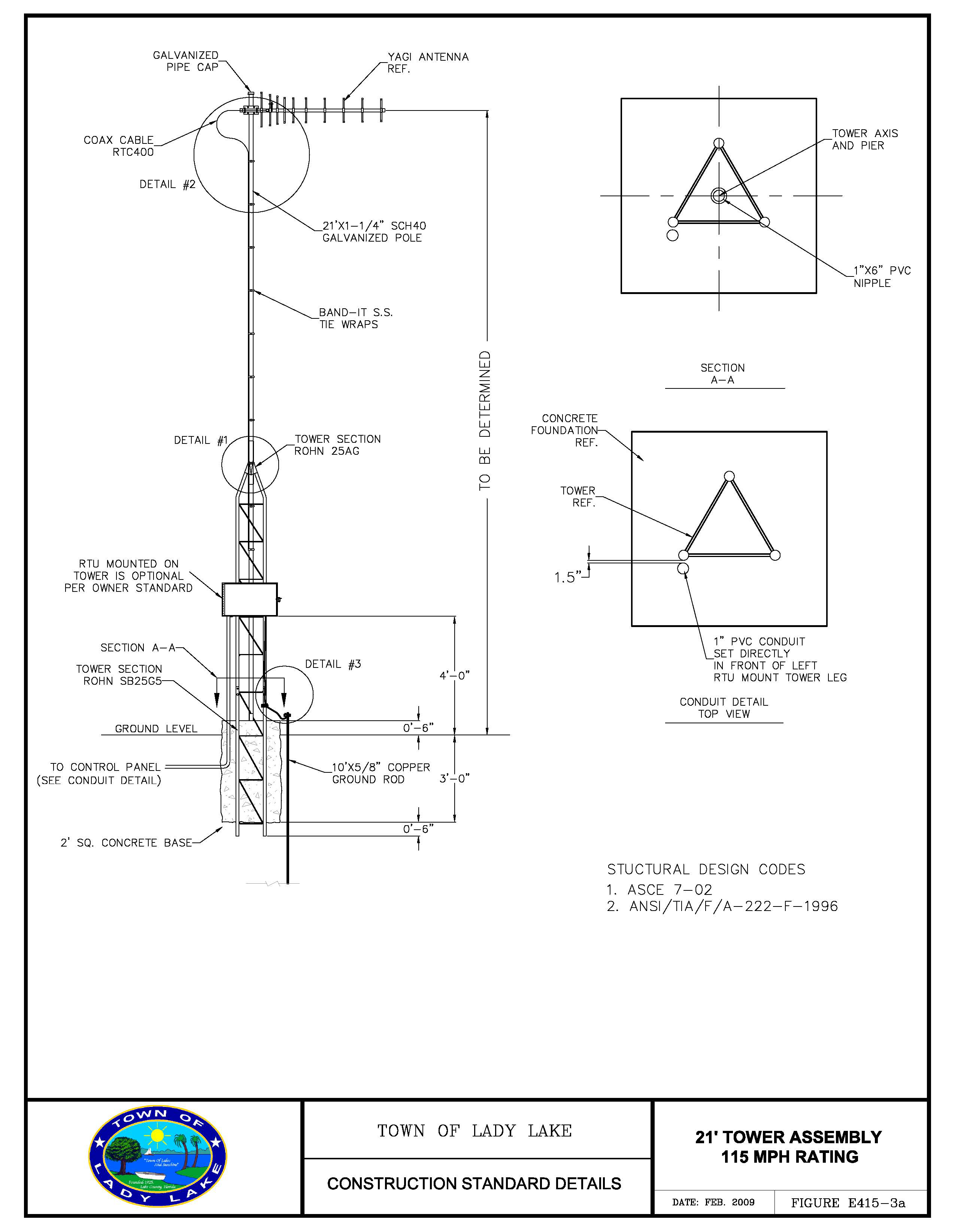
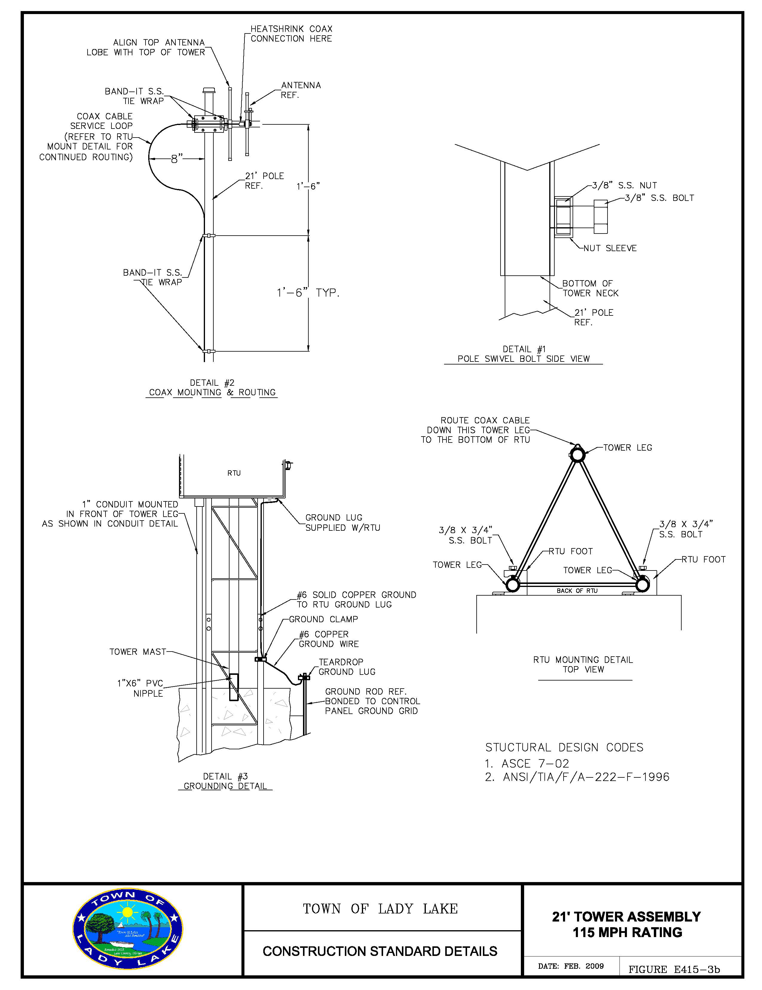
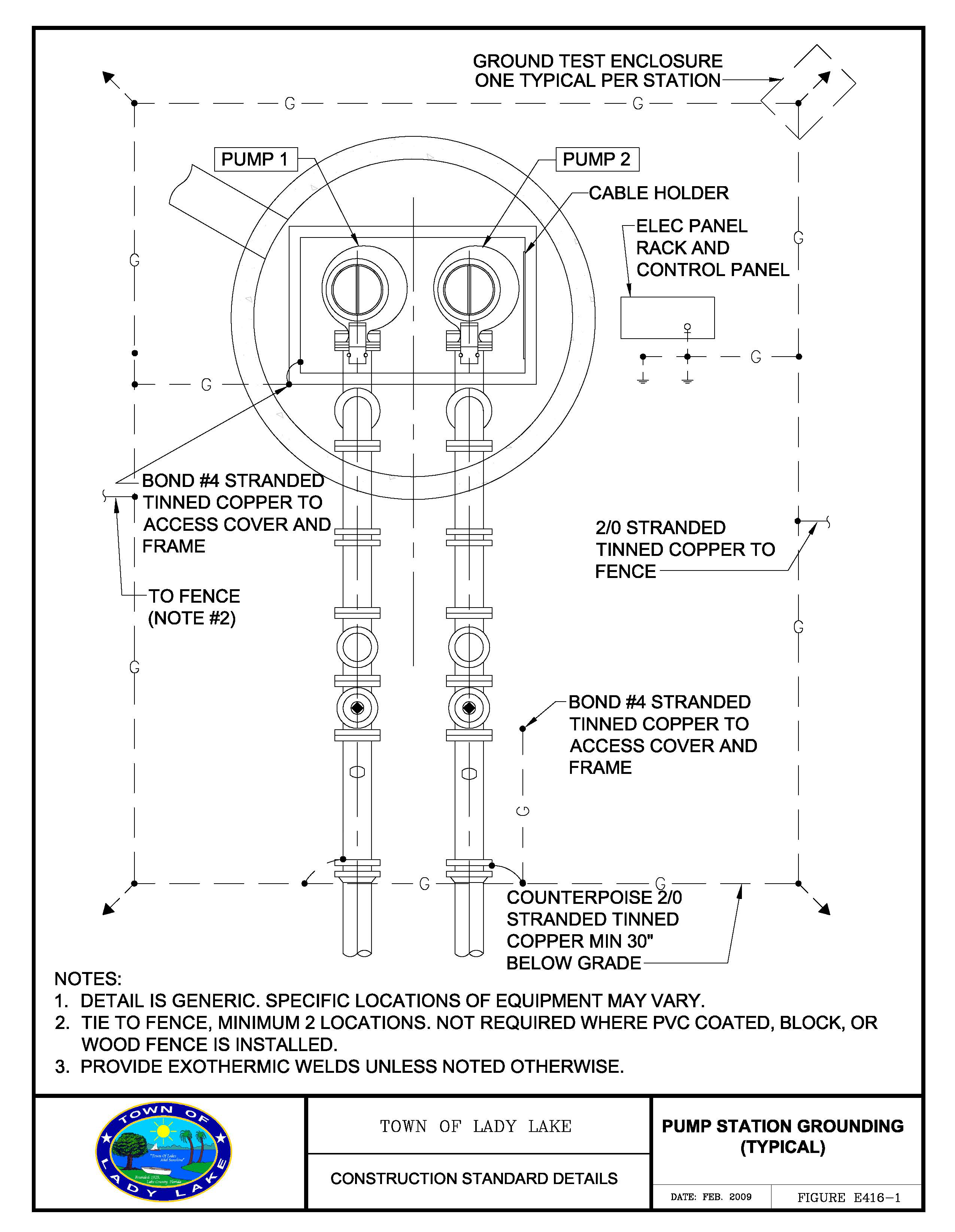
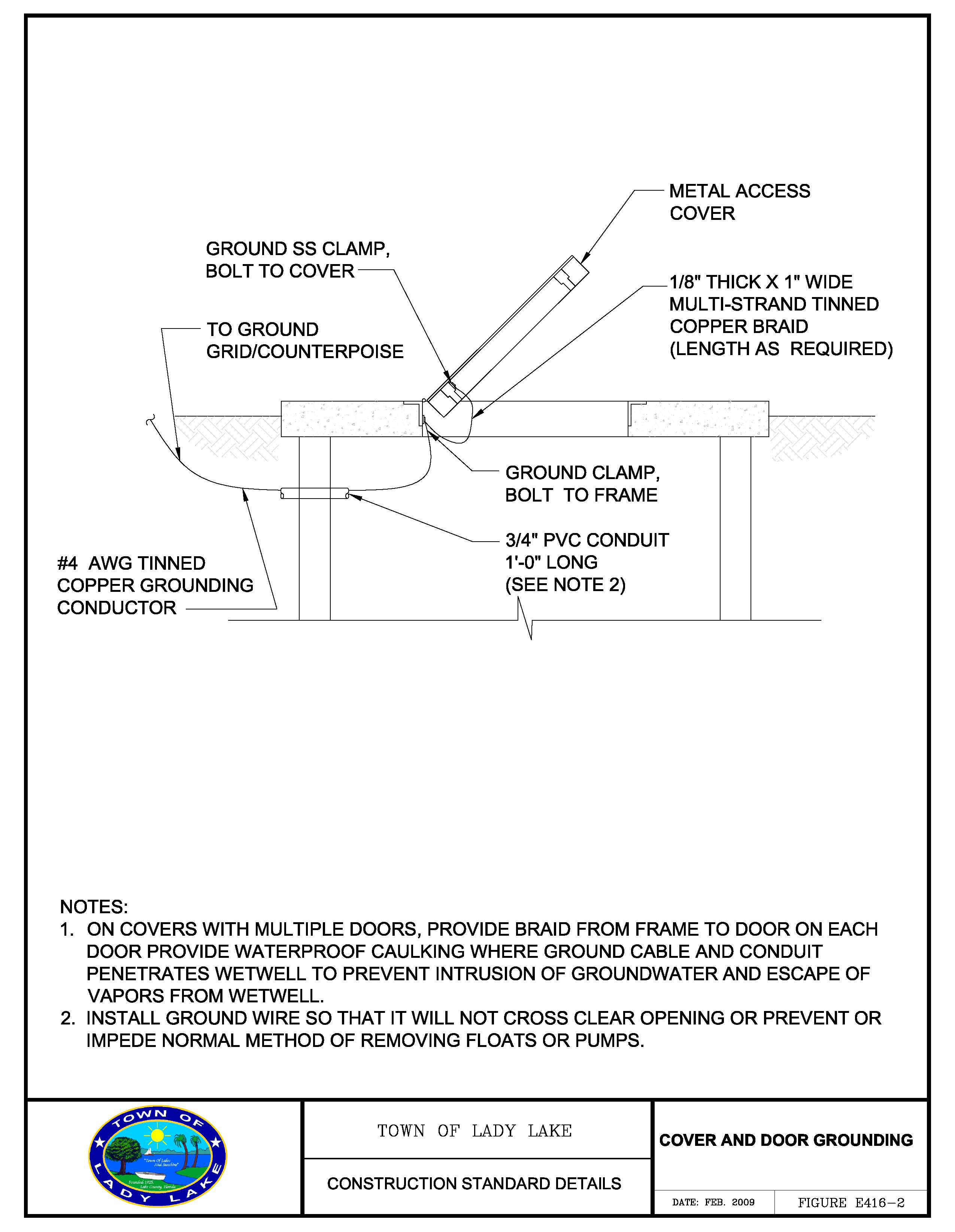
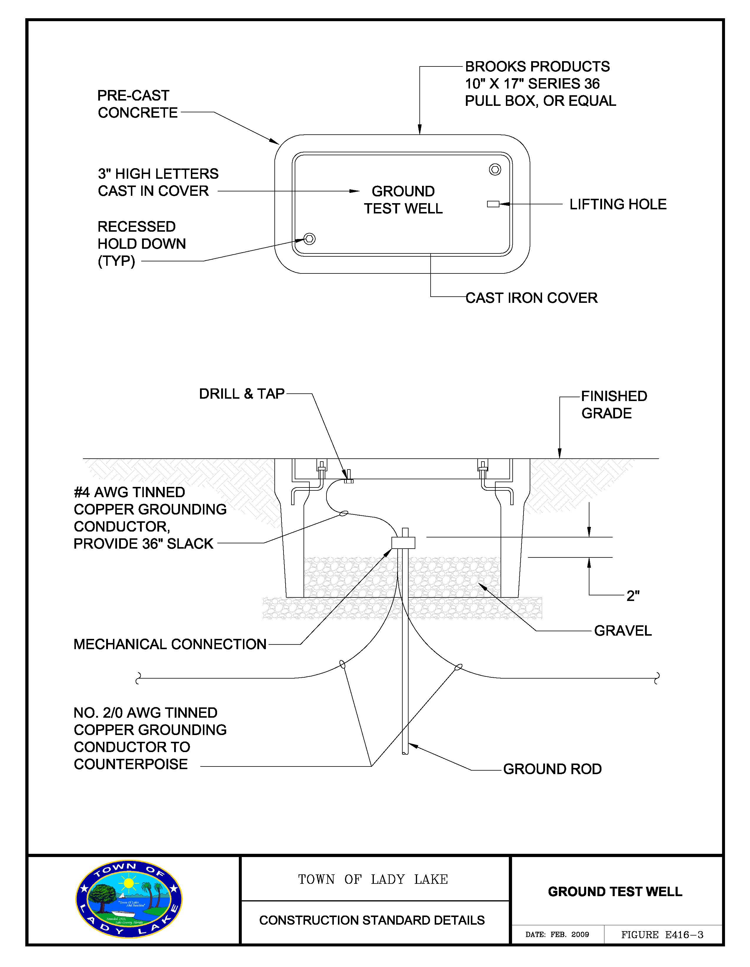
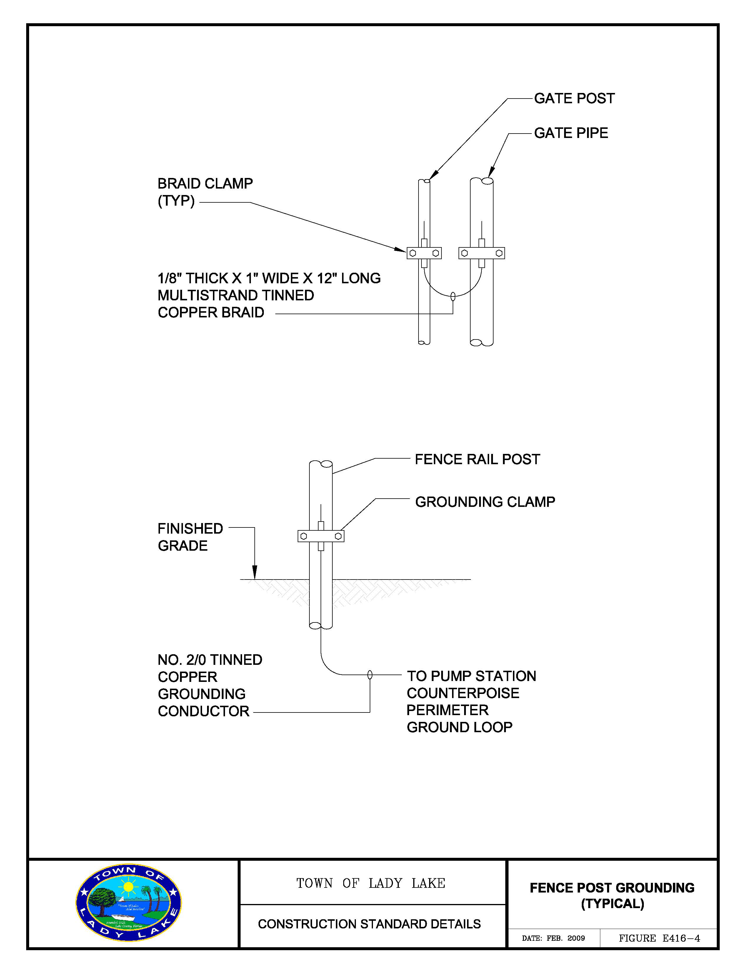
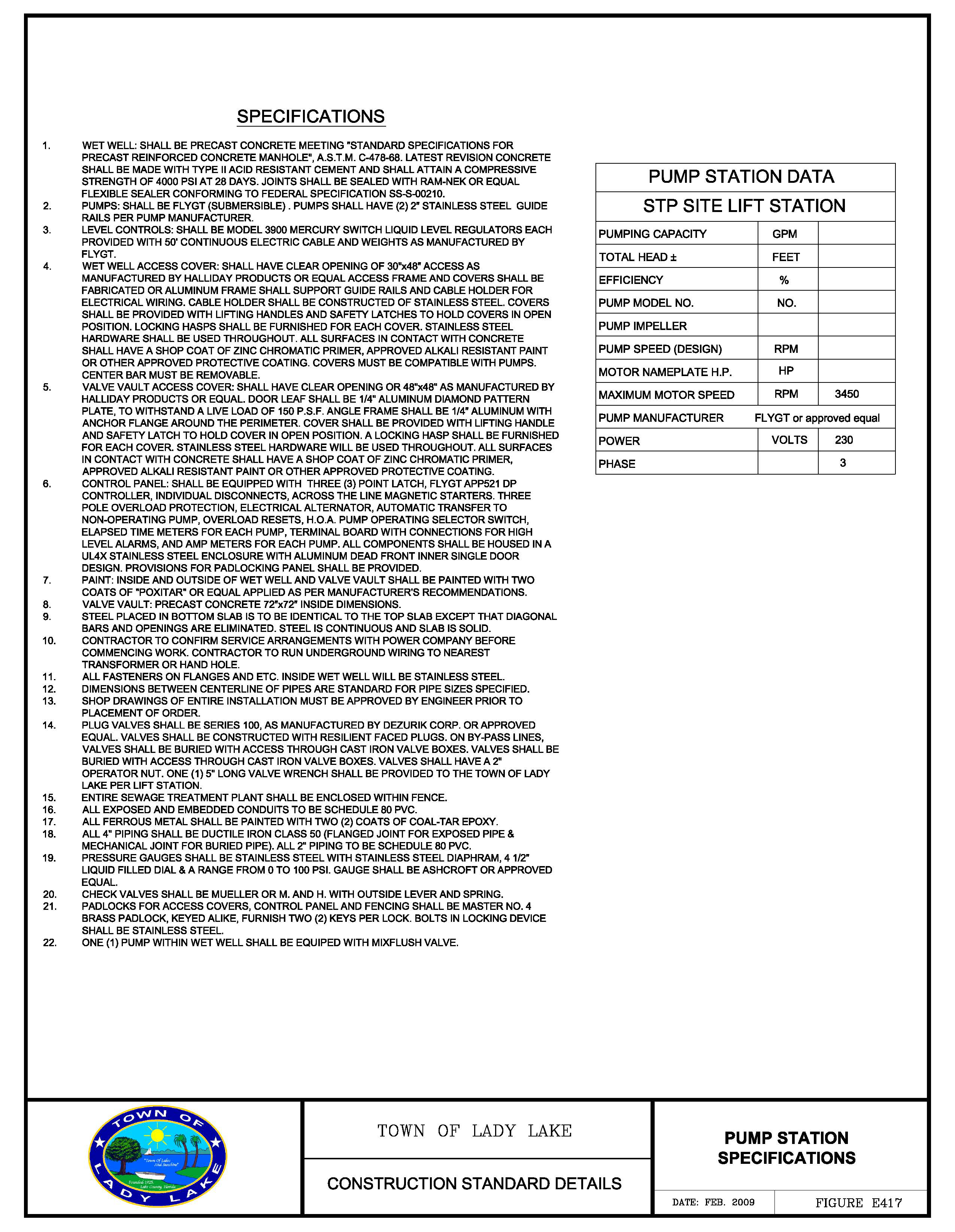
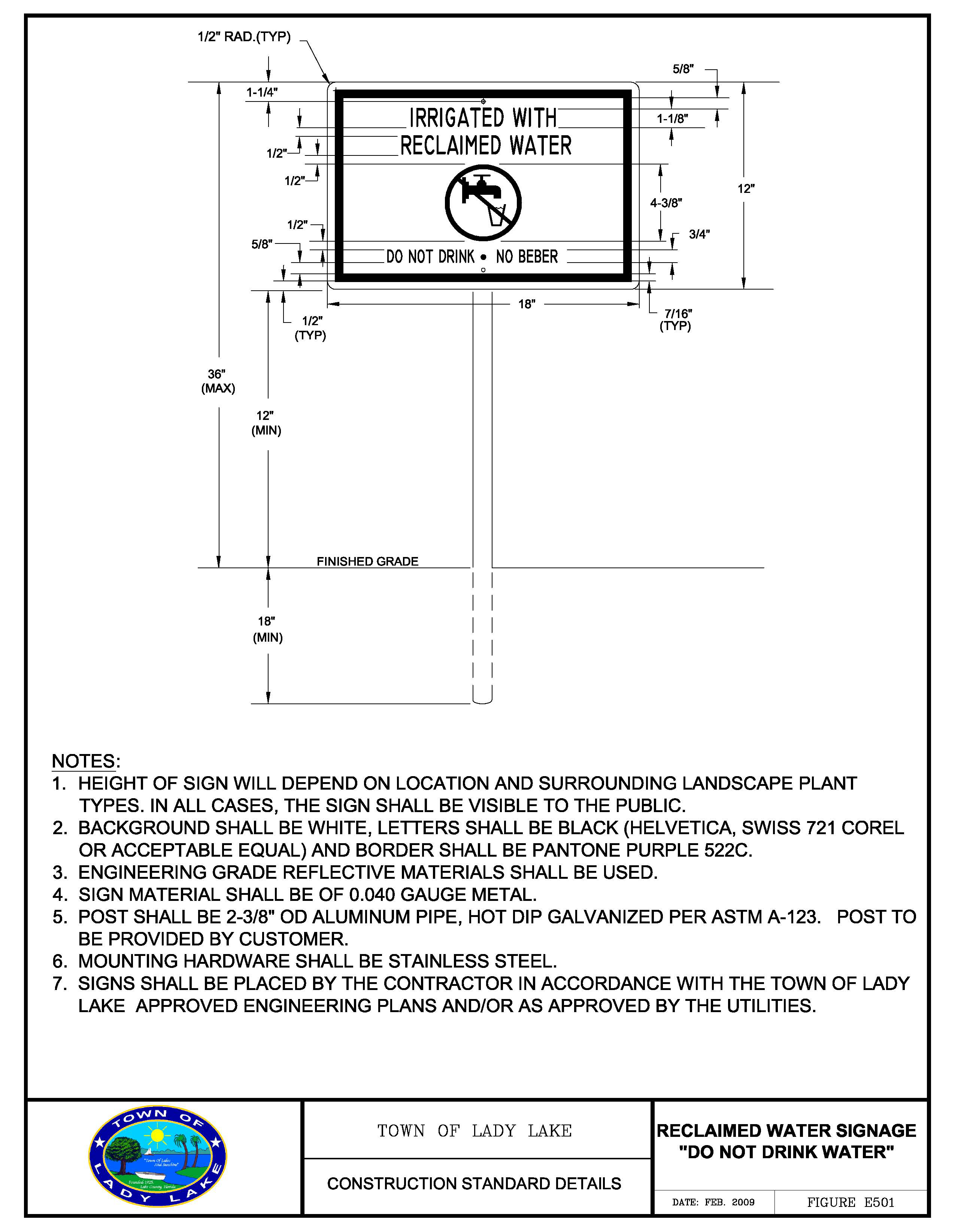
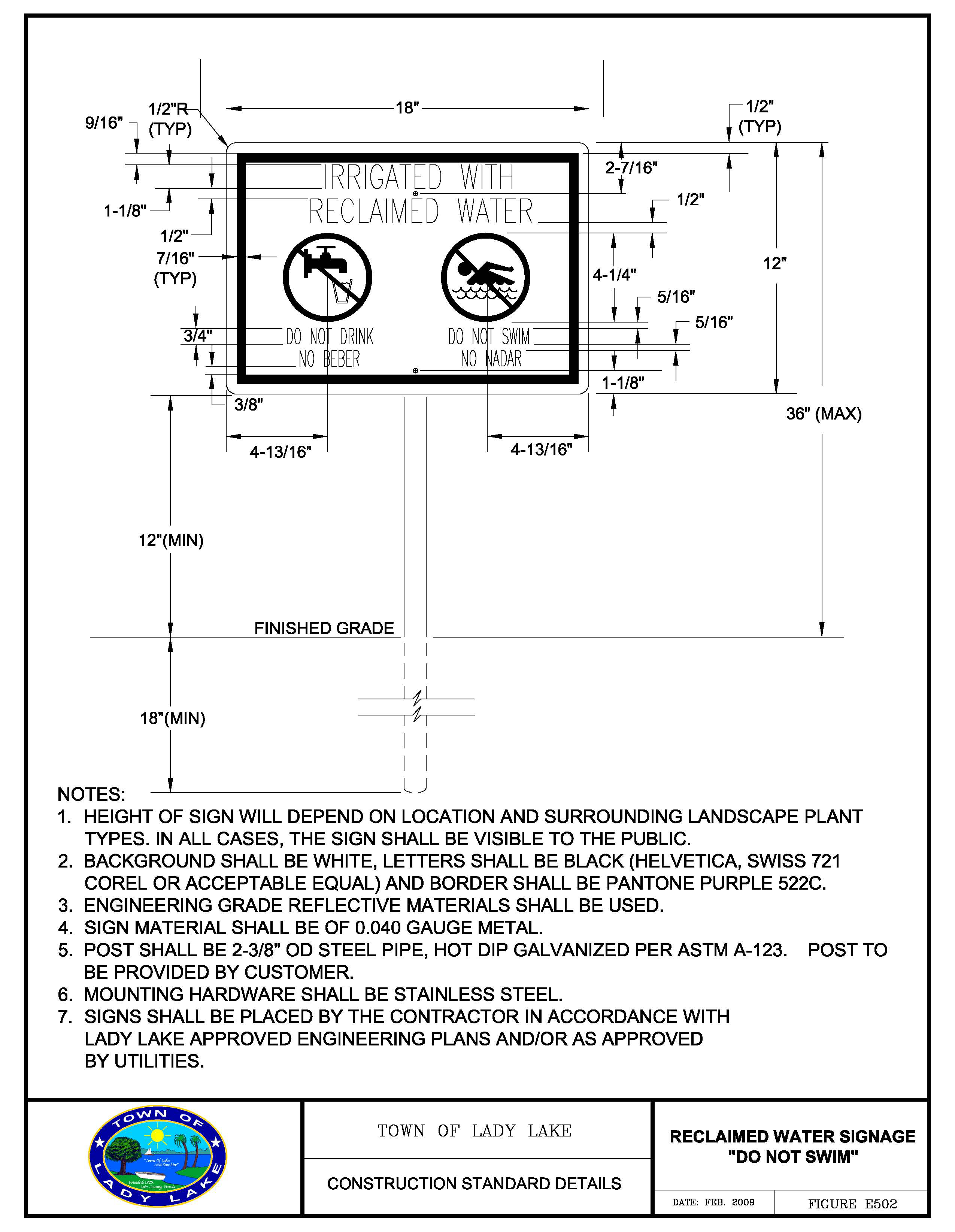
APPENDIX "F" - LIST OF APPROVED PRODUCTS
General Information
The list of approved products shall be used for construction of water, wastewater and reclaimed water utilities to be owned, operated and maintained by utilities. All products shall conform to the current list at the time of the construction plan approval or the date of the construction plan approval extension (if granted). Revisions have been made to the list of approved products as noted in the following table.
Registered recipients of this manual will be notified by email of the pending revisions.
The list of approved products can be acquired from the Town ftp site.
Appendix F has been reorganized into General Information (this page) and three (3) separate sections: Water, Wastewater and Reclaimed Water. The categories of products are now listed alphabetically.
LIST OF APPROVED PRODUCTS
WATER
TABLE OF CONTENTS
Water Category 1 of 5: VALVES AND ACCESSORIES .....LDC14:186
Air Release Valves
Air Release Valves Enclosure
Air Release Valve Vault Frame and Cover
Blow Off Valve
Butterfly Valves 42-inch and above
Gate Valves 16-inch through 48-inch
Gate Valves 12-inch and smaller (resilient seated only)
Sample Station (Above Grade)
Tapping Valves (Resilient Seated Only)
Test Station Box for Buried Valves
Valve Boxes with Locking Lids
Water Meters
Meter Boxes
Water Category 2 of 5: SERVICE MATERIALS .....LDC14:187
Angle Stops Ball Type 1-inch
Angle Stops Ball Type ¾-inch
Brass Service Saddles
Corporation Stops Ball Type
Curb Stops Straight Valves
Polyethylene Tubing
Service Saddles
U Branch
U Branch Assemblies with Angle Ball Valves
Water Category 3 of 5: PIPE .....LDC14:188
Casing spacers (All Sizes)
Casing End Seals
Ductile Iron - Cast Iron Cement Lined
Paint - Aerial Pipe, Fittings and Valves (Field Primer)
Paint - Finish (Exterior)
PCCP Transmission Lines Greater than 30-inch
PVC (Blue) 4-inch to 12-inch
Water Category 4 of 5: PIPE FITTINGS .....LDC14:189
Expansion Joints
Fittings C 153 SSB/C 110 Flange
Restrained Joints - Ductile iron pipe
Restrained Joints - PVC pipe
Tapping Sleeves
Tapping Sleeves - Fabricated steel
Water Category 5 of 5: HYDRANTS .....LDC14:191
LIST OF APPROVED PRODUCTS
WATER
LIST OF APPROVED PRODUCTS
WASTEWATER
TABLE OF CONTENTS
Wastewater Category 1 of 5: VALVES AND ACCESSORIES .....LDC14:195
Air Release Valves
Air Release/Vacuum Relief Valves
Air Release Valve Enclosures
Air Release Valve Frame and Cover
Air Release Valve Service Saddles
Plug Valves - MJ & Flanged
Tapping Sleeve - Fabricated steel mechanical joint
Tapping Sleeve
Tapping Sleeve - Fabricated steel
Tapping Valves - MJ/Ductile Iron
Tapping Sleeve - Mechanical joint Test Station Box for Buried Valves
Valve Box with Locking Lid
Wastewater Category 2 of 5: PIPE .....LDC14:196
Casing Spacers
Casing Spacer End Seals
Ductile Iron Pipe for Valve Vaults
Ductile Iron Pipe Coating and Lining for Pump Station Wet Wells
HDPE Pipe DR 17 (Subaqueous Crossing)
Locating Marker System
Painting Aerial Piping, Fittings and Valves (Field Primer)
Painting Finish (Exterior)
PVC Pipe for Force Mains
PVC Pipe for Gravity SDR 35
Pipe Lining Material — Gravity Mains
Service Lateral Lining
Wastewater Category 3 of 5: PIPE FITTINGS .....LDC14:198
Expansion Joints
Fittings - Ductile Iron
Fittings, Adapters and Plugs - Gravity PVC
Restrained Joints - Ductile Iron Pipe
Restrained Joints - PVC Pipe
Wastewater Category 4 of 5: MANHOLES AND ACCESSORIES .....LDC14:201
Encapsulation
Frame and Cover
Jointing Material
Manhole Interior Lining Systems
Material: Concrete
Pipe Seals Force Main in Wet Well and Valve Box
Pipe Seals Gravity Less than 12-inch
Pipe Seals Manhole Gravity Greater Than or Equal to 12-inch
Surface Coatings - Exterior
Surface Coatings - Interior
Top Adjusting Rings - HDPE
Wastewater Category 5 of 5: PUMP STATION MATERIALS
& ACCESSORIES .....LDC14:202
Alarm Horn (AH)
Alarm Light (AL)
Block Walls: Anti-Graffiti Paint
Biofilters
Control Panels (CP)
Control Panel - Control Circuit Breaker
Control Panel - Control Circuit Transformer
Control Panel - Duplex Receptacle/GFI (DR)
Control Panel - Elapse Time meter (ETM)
Control Panel - Electric Box Mounts
Control Panel - Emergency Circuit Breaker (ECM)
Control Panel - Enclosure
Control Panel - Explosion-Proof Seal-off
Control Panel - Flasher (FL)
Control Panel - Float Regulator (FR)
Control Panel - Fuses
Control Panel - Hand-Auto-Off Selector (HOA)
Control Panel - Horn Silence Button (HSS)
Control Panel - Moisture and Temperature Failure Light (MT)
Control Panel - Motor Circuit Breaker (MB)
Control Panel - Motor Starter (MS)
Control Panel - Overload Heater (OL)
Control Panel - Phase Monitor (PM)
Control Panel - Pilot Light (PL)
Control Panel - Pump Automatic Alternator (PAA)
Control Panel - Relay (R)
Control Panel - Resistor (RE)
Control Panel - Run Indicator (RI)
Control Panel - Supplemental Protector Breaker 3-pole, 1-amp
Control Panel - Surge Protector
Control Panel - Terminal Strip (TS)
Flow Meters with Replaceable Sensors
Generator Circuit Breaker
Generator Fuel Tanks
Generator Systems
Generator Systems (Portable)
Generator Receptacle
Generator Transfer Switch
Main Service Disconnect Breaker
Main Circuit Breaker
Main Circuit Transformer
Odor Control Monitoring Instrument
Pressure Gauges
Pressure Gauges (Diaphragm Seals)
Pressure Transducers - 0 to 15 psi Range
SCADA Panels type 1
SCADA Panels type 2
SCADA Panels type 3
Sluice Gates for Wet Wells
Submersible Pumps with Enclosed Impellers
Valves (Check)
Valves (Cushion Check Oil Filled)
Variable Frequency Drives
Variable Frequency Motors
Wet Well and Valve Vault Access Frames and Covers
Wet Well Lining System
LIST OF APPROVED PRODUCTS RECLAIMED WATER
TABLE OF CONTENTS
Reclaimed Water Category 1 of 4: VALVES AND ACCESSORIES .....LDC14:211
Air Release Valves
Air Release Valves: Enclosures
Air Release Valves: Vault Frame and Cover
Blow Off Valve
Butterfly Valves 42" and above (8 mil epoxy coated and lined (AWWA)
Gate Valves 12" and smaller (resilient seated only)
Gate Valves 16" to 48" (resilient seated only with side actuators)
Pressure Gauges
Pressure Sustaining/Pressure Reducing with Shutoff
Pressure Sustaining/Pressure Reducing with Flow Control Valve
Sample Station (above grade)
Tapping Valves
Test Station Box lot- Buried Valves
Valve boxes with Square Covers and Locking Lids
Wye Strainers, 4" and above
Reclaimed Water Category 2 of 4: SERVICE MATERIALS .....LDC14:213
Angle Stops: Ball type 1" and 2" CTS U.D. tubing by 5/8" 3/4" and 2" meter.
Angle Stops: Ball type 3/4" FIP by 5/8" × 3/4" meter.
Corporation Stops: Ball type 1" and 2" with AWWA taper CC threads only/pack joint outlet for CTS
Curb Stops — Straight Valves: Curb stop to be ball type, reduced port FIP × FIP 3/4" × 3/4"
Curb Stops — Straight Valves: Ball type compression by meter, 1" and 2" CTS O.D. tubing by 5/8" × 3/4" meter.
Curb Stops — Straight Valves: Ball type compression × compression.
Polyethylene Tubing: blue with UV protection (SDR-9) 1-inch and 2-inch only
Reclaimed Water Meter 8" and above
Service Saddles, Brass: Service saddles can be hinged or bolt controlled O.D. saddles to be used on C-900 and IPS O.D. PVC pipe.
Service Saddles: Epoxy or nylon coated stainless steel 18-8 type 304 straps, CC threads — 2" to be iron pipe threads controlled O.D. PVC pipe, double straps to be 2" minimum width each, single strap to be minimum 3" width.
U Branch: (1" × 3/4" × 7-1/2").
U Branch Assemblies with Angle Ball Valves: (1" × 3/4" × 7-1/2").
Reclaimed Water Category 3 of 4: PIPE MATERIAL .....LDC14:215
Casing spacers (all sizes): Stainless steel with vinyl runners
Casing end seals
Ductile iron/Cast iron: Cement lined (4" to 12" = Class 350, 16" to 24" = Class 250, 30" to 64" = Class 200).
Paint: Aerial pipe, fittings and valves (field primer)
Paint: Finish (exterior)
Paint: Above Ground Meter Assemblies:
PVC (Pantone 522C): 4 to 12-inch — AWWA C-900, DR14, DR 18
Reclaimed Water Category 4 of 4: PIPE FITTINGS .....LDC14:217
Expansion Joints
Fittings C153 SSB/C110 Flange: Cement or fusion bonded epoxy lined.
Restrained Joints: Ductile iron pipe.
Restrained Joints: PVC pipe
Tapping Sleeves: Ductile Iron/Cast Iron M.1 type
Tapping Sleeves: Fabricated steel, mechanical joint, fusion bonded epoxy coated.