
Rogers City Zoning Code
ARTICLE 6
ENGINEERING MANUAL
PART II – STANDARD SPECIFICATIONS
ARTICLE I. GENERAL
Article I. CITY OF ROGERS STANDARD DETAILS
These details shall be used on all projects within the public rights-of-way, easements or on municipal projects. ARDOT standard details shall prevail within Arkansas Highway Commission rights-of-way.
See Appendices for the submittal specifications for the decorative street lights.
I. WAYFINDING SIGNAGE
These signs may only be used with the express, written permission of the Community Development Director and at locations determined by the City.
IV. GPS MONUMENTATION FORM

V. STREET LIGHT SUBMITTAL SPECIFICATIONS
VI. CONCRETE INTEGRAL COLOR CHART
Section 1.01 Intent
This Manual and the criteria, standards, and specifications contained herein shall be required for all development, redevelopment, and municipal projects within the jurisdiction of the City of Rogers, including construction by City crews. All redevelopment and improvements to existing streets, whether by public or private entities, require all streets and improvements in public rights-of-way and easements be brought into compliance with current codes unless waived in writing by the Community Development Director. The City’s review and approval of any plans, reports, or drawings or the City’s inspection and approval of any improvements constructed by the developer in accordance with this Manual, does not constitute a representation, warranty, or guarantee by the City that such improvements are free from defects or will operate adequately for the purpose intended.
The chapters and appendices that make up this Manual pertain to planning, design, approval, construction, inspection, testing, and documentation of street, drainage, and trail improvements. The intent of this Manual is to establish the minimum acceptable standards.
Where conflict between this Manual and other City Code exists, the Code shall govern. In case of discrepancy within this Manual, the most stringent requirement will apply.
This manual may be periodically reviewed by the Director of Community Development. All amendments to this Manual shall be approved by Rogers City Council.
(Ord 25-35, 7-8-2025)
Section 1.02 Abbreviations.
The following abbreviations, when used in this Manual, shall represent the following descriptions:
AASHTO American Association of State Highway and Transportation Officials
ACHM Asphaltic Concrete Hot Mix
ACI American Concrete Institute
ADEE Arkansas Department of Energy and Environment, formerly ADEQ
ADEQ Arkansas Department of Environmental Quality, see ADEE and DEQ
ADT Average Daily Traffic
AHTD Arkansas Highway and Transportation Department, see ARDOT
ANSI American National Standards Institute
AOAC Association of Official Agricultural Chemists
ARDOT Arkansas Department of Transportation, previously known as AHTD
ASTM American Society for Testing and Materials
AWPA American Wood Preservers Association
CRSI Concrete Reinforcing Steel Institute
CS base, CSB Crushed Stone Base
CT base, CTB Cement Treated Base
DBS Double Bituminous Surface Treatment
DEQ Division of Environmental Quality within ADEE, formerly ADEQ
EAL Equivalent Axle Load, usually 18-kip EALs
EPA Environmental Protection Agency
FHWA Federal Highway Administration
ITE Institute of Traffic Engineers
LBS Pounds
LL Liquid Limit
Mils One-thousandth of an inch or 0.001 inch
MUTCD Manual on Uniform Traffic Control Devices
NACTO National Association of City Transportation Officials
NEMA National Electrical Manufacturers Association
NPDES National Pollutant Discharge Elimination System
OSHA Occupational Safety and Health Administration
PC Point of Curvature
PI Plastic Index or Point of Intersection
PL Plastic Limit
PROWAG Accessibility Guidelines for Pedestrian Facilities in the Public Right-of-Way
PSI Pounds per Square Inch
PT Point of Tangency
PVC Polyvinyl chloride
SWPPP Storm Water Pollution Prevention Plan
TIA Traffic Impact Analysis
UL Underwriter’s Laboratory
USACE U.S. Army Corps of Engineers
USDA U.S. Department of Agriculture
VTCSH Vehicle Traffic Control Signal Heads
(Ord 25-35, 7-8-2025)
Section 1.03 Definitions
AASHTO T 99 (Standard Proctor): A laboratory determination of the maximum density to which a soil can be compacted using a 5½-pound hammer and a 12-inch drop.
AASHTO T 180 (Modified Proctor): A laboratory determination of the maximum density to which a soil can be compacted using a ten-pound hammer and an 18-inch drop.
Developer: Any person(s), parties, partnerships, or corporations, private or public, engaging in activities described as development.
Development: Shall include, but shall not be limited to, the construction of a new improvement, the construction of an addition to an existing improvement, or a parceling which results in the need for access and utilities.
Engineer, Engineer of Record: The person or company responsible for the creation and submission of contract documents or construction plans for the purpose of one-time construction of a facility, working on behalf of the developer. This person shall be an Arkansas licensed professional engineer.
Quality Control (QC) Laboratory: The company responsible for overseeing and testing the quality of the materials provided on the project. This will be considered the same as the material testing laboratory.
ROW: Right-of-way. The land opened, reserved, or dedicated for streets, sidewalks, trails, drainage or other purposes
Specifications: Construction specifications and standards adopted by the City.
UDC: City of Rogers Unified Development Code.
(Ord 25-35, 7-8-2025)
Section 2.01 General
- The plan sheets for improvements shall be formatted to fit on 22”x34” sheets with all sheets in a plan set being the same size. Plan drawings shall be of an appropriate scale to be legible; the suggested scale is typically 1”=20’ with 1”=50’ the typical maximum scale. Legibility will be determined by the City’s engineering or planning staff. Profile drawings shall be provided for all storm sewers and drainage ditches at a suggested scale of 1”=20’ horizontal and 1”=5’ (minimum) vertical.
- Plan sheets shall conform to generally accepted engineering practices; special conditions may require additional information.
- All plans, studies, analyses, and reports must be signed, sealed and dated by an Arkansas licensed professional engineer.
- All development plans must be stamped by Community Development. No work is authorized unless it contains this stamp.
(Ord 25-35, 7-8-2025)
Section 2.02 Title Sheet
- The title sheet shall include:
- Project name, nature of the project, city and state.
- Index of sheets.
- A location or vicinity map showing the project in relation to existing streets, railroads, and physical features. The location map shall have a north arrow and an appropriate scale.
- A project control benchmark identified and referenced to the City of Rogers GPS control monuments.
- The name and address of the owner of the project and the engineer preparing the plans.
- Engineer’s seal, signature and date.
Section 2.03 Layout Sheets
- In general, layout sheets shall contain the following:
- North arrow and scale.
- Legend of symbols.
- Name of project.
- Boundary line or project area.
- Location and description of existing major drainage facilities within or adjacent to the project area.
- Location of proposed drainage facilities.
- Location and description of utilities within or adjacent to the project area.
- Provide match lines if more than one sheet is necessary.
- The date, registration seal, and signature of the Engineer of Record.
- Elevations shown in the plans shall be based on City of Rogers GPS control monuments.
- The top of each page shall be either north or west. The stationing of street plans and profiles shall be from left to right and downstream to upstream for channels.
- Show topography a minimum of 20’ beyond the project area; 50’ for channel improvements.
- Show existing and proposed property and easement lines with dimensions.
- Minimum finish floor elevations shall be shown a minimum of 3-feet above the 100-year water surface elevation on each lot when located in a special flood hazard area, other flood hazard areas, and adjacent to areas. All occupied buildings, whether in or out of a designated floodplain shall have the finished floor elevation a minimum of 12-inches above the land immediately surrounding the building, and all buildings in a subdivision are required to have the finished floor a minimum of 12” above the curb.
- Provide a plan and profile of any wall 4’ or more in height.
- Include current Standard Details as needed, see PART III – STANDARD DETAILS.
Section 2.04 Drainage
- Refer to Drainage Criteria Manual for criteria and design information.
Section 2.05 As-built Drawings and Certifications
- Final as-built plans and a certification letter shall be submitted to the City’s Planning Office upon completion of all work for development projects. For city projects, the as-built plans shall be submitted to the City Engineer and shall include as-built irrigation, landscaping, and electrical plans in addition to the roadway and drainage as-built plans. All property lines, easements, rights-of-way, street names, and property addresses must be depicted on the as-built plans. All Operating and Maintenance manuals shall be provided to the City. The certification letter shall be signed and sealed by the Engineer of Record affirming that all improvements have been constructed as shown in the as-built plans which shall conform to the approved construction plans except for modifications approved through the City. All improvements must be in place and as-built plans, certifications, a one-year maintenance bond for 100% of the cost of drainage improvements, a one-year maintenance bond for 50% of the cost of right-of-way improvements, and easements provided to the City Planner prior to Final Plat for a subdivision or issuance of the Certificate of Occupancy for a Site Development. As-built plans shall be based on surveyed data of the constructed improvements and reflect all changes made during construction. As-builts must be signed and sealed by a registered Arkansas professional engineer. As-builts will be submitted on:
- An AutoCAD .dwg file formatted to AutoCAD 2022 or newer
- One PDF copy of the as-built plans and drainage report
- Shapefiles. Refer to PART IV – APPENDICES, ARTICLE III SHAPEFILE AS-BUILT SUBMITTAL CRITERIA for detailed submittal criteria for shapefiles.
- GPS Monumentation. All subdivisions require a minimum of two (2) survey monuments to be set prior to Final Plat that are tied to the Rogers reference monuments. Refer to PART IV – APPENDICES, ARTICLE IV GPS MONUMENTATION FORM for additional information.
- Bonds/warranties
- The warranty period for all public improvements shall be one year except that the warranty period for landscaping shall be three years. During the warranty period, the developer/contractor shall guarantee the work to be free of any damage or defect in workmanship and material. This damage or defects does not include normal wear and tear. The warranty period shall start from the date of Final Completion for all city projects and from the date of the Certificate of Occupancy or Final Plat for development projects. If deficiencies are noted during the warranty period, the developer/contractor shall repair the deficiencies at no cost to the City.
- A warranty guarantee shall be required for the entire warranty period. The warranty guarantee shall be in the form of a maintenance bond or cash deposit. The guarantee shall be in the amount of 50% of the total value of the right-of-way improvements for the project, and 100% of the total value of the drainage improvements.
- Once notified of a deficiency, the developer/contractor shall have 30 calendar days to repair the work unless there is imminent danger to the public health, safety, and welfare, in which case it shall be made safe immediately and the repair shall be made within 24 hours. Written extensions to these times may be granted for unusual circumstances or weather delays by the City Engineer.
- If the developer/contractor does not complete the warranty repairs in the time frame specified, the City may choose to affect the necessary repairs. The City may invoice the developer/contractor directly for all costs or collect from the guarantee.
(Ord 25-35, 7-8-2025)
Section 3.01 General
- Vision Zero
- Policy. The City has adopted the Northwest Arkansas Vision Zero Plan and established a target of 2040 to eliminate fatal and serious injuries. The goals of this plan include:
- Promote a culture that prioritizes people’s safety,
- Reduce conflicts between roadway users,
- Establish policies, practices, and programs that focus on safety at all levels, and
- Slow vehicles.
- The policies and design standards in this Manual are adopted in order to meet these goals.
- Policy. The City has adopted the Northwest Arkansas Vision Zero Plan and established a target of 2040 to eliminate fatal and serious injuries. The goals of this plan include:
- Complete streets.
- Policy. The City shall develop a safe, reliable, efficient, integrated and connected multimodal transportation system that will promote access, mobility and health for all users, and will promote the safety and convenience of all users of the public transit, people of all ages and abilities, motorists, emergency responders, freight providers and adjacent land users.
- Scope of applicability.
- All city-owned transportation facilities in the public right-of-way, including, but not limited to, streets, bridges, and all other connecting pathways, shall be designed, constructed, operated, and maintained so that users of all ages and abilities can travel efficiently and independently. Private streets shall be designed to the same standards as if they were a public street.
- The City shall approach every transportation improvement and project phase as an opportunity to create safer, more accessible streets for all users. These phases include, but are not limited to: planning, programming, design, right-of-way acquisition, construction, construction engineering, reconstruction, operation, and maintenance. Other changes to transportation facilities on streets and rights-of-way, including capital improvements, re-channelization, projects and major maintenance, must also be included.
- Design standards. The City shall follow nationally recognized design standards and use the best and latest design standards available. These standards include, but are not limited to: ITE Designing Walkable Urban Thoroughfares: A Context Sensitive Approach; AASHTO Guide for Development of Bicycle Facilities, AASHTO Guide for Planning, Designing and Operating Pedestrian Facilities, FHWA Bikeway Selection Guide, NACTO Urban Street Design Guide, the NACTO Urban Bikeway Design Guide, and PROWAG Public Right of Way Accessibility Guidelines.
- Federal/State Coordination
- Any street or roadway construction involving federal and/or state department of transportation funds shall meet the federal/state requirements.
- All work in federal or state right-of-way or control-of-access shall require a permit through ARDOT in addition to any city permits required.
- Street Grid
- Policy. The City intends to extend and create a rectilinear grid of streets similar to that established in Downtown in order to address the future transportation needs of the city. This grid shall provide for pedestrian, bicycle, and vehicular modes of transportation as well as freight and transit where appropriate, while generally aligning with the established street grid pattern. This grid will provide permeability to the transportation network without requiring large-scale widening of the collector and arterial system, which can destroy the fabric of the community.
- Scope of applicability.
All streets required by the Master Street Plan and the Unified Development Code lot and block standards shall be publicly dedicated in a manner prescribed by the Director and gates shall not be allowed on them. Streets other than these may be private.- Any private street shall be located on a separate tract and owned and maintained by a Property Owners Association or the property owner. The tract shall have an access easement encompassing the private street, and the covenants (if applicable) shall be reviewed and approved by the Department of Community Development to ensure maintenance is addressed prior to being recorded. Private streets shall meet the same design criteria as public streets.
(Ord 25-35, 7-8-2025)
Section 3.02 Traffic Impact Analysis
- The City may require a Traffic Impact Analysis (TIA) if the development meets one of the following conditions:
- Generates ~100 trips/peak hour,
- Generates ~1000 trips/day,
- Contains ~100 acres or more in the development, or
- The City Engineer determines that other development-specific conditions warrant.
- Trip generation rates shall be based on the ITE Trip Generation Manual.
- The purpose of the TIA is to identify impacts to the transportation network and recommend improvements to mitigate these impacts as necessary. The transportation network includes bicycle and pedestrian facilities as well as vehicular facilities.
- See PART IV – APPENDICES, ARTICLE I TRAFFIC IMPACT ANALYSIS FORMAT for TIA format and analysis requirements.
- The projected traffic analysis shall be based on a 20-year, full-buildout condition with growth factors approved by the City Engineer.
(Ord 25-35, 7-8-2025)
Section 3.03 Street Design Criteria
- Street geometry.
- Studies have shown that the chance of a fatality for a pedestrian when struck by a vehicle increases rapidly with impact speed. Streets within the city shall be designed to accommodate all expected users. The design of the street shall be such that the geometry of the street will reinforce the desired driving behavior. A signed speed limit does not work without the structure of the roadway design to reinforce it.
- Traffic calming methods are required in the design of minor streets. Tangent lengths shall not exceed 500 feet for Minor Streets. Studies indicate that operating speeds were 30 mph or less when the tangent sections were no longer than 500 feet. Long tangent sections can be segmented by conditions that require a complete stop, such as a T-intersection, or by conditions that require reduced speeds, such as a traffic calming device. Devices that are suggested for new developments include roundabouts, traffic circles, chicanes, and curb extensions (bulb-outs). On-street parking can also be an effective method for traffic calming. Curb extensions are required when on-street parking is proposed to provide for intersection daylighting and water infiltration/filtration opportunities. Traffic calming measures shall make provisions to accommodate bike lanes where both are proposed. Curb extensions and chicanes shall be designed with a minimum 20-foot internal radii and 10-foot external radii on all transitions to accommodate street sweepers.
- On-street parking will generally be required on all streets except for boulevard typologies or service road typologies, where unsafe due to high-speeds, not allowed because of ARDOT control, or other similar factors which will require approval by the City Engineer to eliminate the on-street parking.
- Traffic calming methods are required in the design of minor streets. Tangent lengths shall not exceed 500 feet for Minor Streets. Studies indicate that operating speeds were 30 mph or less when the tangent sections were no longer than 500 feet. Long tangent sections can be segmented by conditions that require a complete stop, such as a T-intersection, or by conditions that require reduced speeds, such as a traffic calming device. Devices that are suggested for new developments include roundabouts, traffic circles, chicanes, and curb extensions (bulb-outs). On-street parking can also be an effective method for traffic calming. Curb extensions are required when on-street parking is proposed to provide for intersection daylighting and water infiltration/filtration opportunities. Traffic calming measures shall make provisions to accommodate bike lanes where both are proposed. Curb extensions and chicanes shall be designed with a minimum 20-foot internal radii and 10-foot external radii on all transitions to accommodate street sweepers.
- The vertical street profile shall be designed so that crosswalks meet PROWAG requirements for cross-slope.
- Policy. Intersections are vital to the functioning of the city’s road network but they create conflict points within the system and are generally where the majority of crashes occur. As such, intersection design is critical to meeting the Vision Zero goals. Since studies show that roundabouts are substantially safer, roundabouts shall be the preferred alternative for all collector and higher classification street intersections and implemented where feasible. Roundabouts, mini-roundabouts, and traffic circles (where appropriate) shall be the preferred alternative for minor and local streets as well. The final decision on which intersection control measure to implement will be made by the City Engineer. Some design concerns that may warrant other treatments than roundabouts might include very high traffic volumes, pedestrian prioritization in pedestrian-intensive locations, space constraints, or topography.
- Intersection right-of-way control shall follow MUTCD guidelines including but not limited to Chapter 2B Section 2B.01 through 2B.10. Four-way stop conditions should be avoided on low volume streets because there will be a tendency for the stop to be ignored and that has potential to train drivers that 4-way stops don’t really mean “stop.” Any proposal for four-way stops must be reviewed and approved by the City Engineer.
- Roadway centerlines at intersections must align within 12-feet maximum offset for all roadway classifications. Exceptions to this may be made for roundabouts and minor streets may have an offset if the minimum separation is 75 feet.
- Design Vehicle
- Intersections shall be designed to accommodate the following design vehicles.
- All streets shall be designed to allow a fire truck to turn from one street to the next and remain in the correct lane. For roundabouts, the vehicle shall remain in the circulatory roadway except for mini-roundabouts where the vehicle can use the entire roadway.
- Truck routes shall be designed to accommodate WB-67 interstate semitrailers. This may include the use of compound curves or truck aprons to allow for off-tracking at corners; see Truck Aprons section below.
- All roundabouts on Collectors and Arterials shall be designed to accommodate a WB-67. Truck aprons shall be used to minimize the inscribed diameter of the roundabout, especially to accommodate the turning movements. Signs, light poles, signal poles, etc., shall be located in such a manner that they will not be hit or damaged by the WB-67
- For special circumstances, other design vehicles may be required by the City Engineer.
- The minimum intersection turn radii shall be provided at all intersections to reduce pedestrian crossing distances.
- Intersections shall be designed to accommodate the following design vehicles.
- Turn Lanes
- Right turn lanes are discouraged in pedestrian areas due to the higher vehicular speeds. The use of these turn lanes will be evaluated on a case-by-case basis and only allowed upon approval of the City Engineer.
- A Traffic Impact Analysis shall be provided to warrant the addition of left turn lanes and shall be subject to approval by the City Engineer.
- Truck Aprons
- Truck aprons shall be used on the inside of the circulatory roadway in roundabouts.
- Truck aprons on the exterior of the roundabout may only be used when approved in writing by the City Engineer.
- Truck aprons at any intersection other than a roundabout require written approval by the City Engineer.
- Truck aprons will be constructed per the details provided in PART III -STANDARD DETAILS.
- Bikeway Crossings
- Bikeway crossings shall match the details shown in PART III – STANDARD DETAILS.
- For special circumstances, other additional details may be required by the City Engineer.
- Sight Distances
- All sight distances will be calculated per the current edition of the AASHTO Greenbook
- Depict the intersection sight triangles in the plans on a sheet that delineates all other vertical obstructions such as buildings, trees, landscaping, fences, utilities etc.
- The intersection sight triangles must be contained within the public right-of-way or easement.
- Obstructions to sight distances.
- If there exists an obstruction inside a sight triangle, the City may remove said obstruction, after providing, at a minimum, seventy-two (72) hours’ notice to the owner of the obstruction, if the owner of the obstruction is known. If the owner is unknown, the City will post notice on the obstruction for a period of seventy-two (72) hours for it to be removed prior to its removal by the City.
- Emergency. If the obstruction is declared an emergency by either the City Engineer or the Director of Community Development, the obstruction may be immediately removed from the sight triangle.
- Studies have shown that the chance of a fatality for a pedestrian when struck by a vehicle increases rapidly with impact speed. Streets within the city shall be designed to accommodate all expected users. The design of the street shall be such that the geometry of the street will reinforce the desired driving behavior. A signed speed limit does not work without the structure of the roadway design to reinforce it.
- Intersection Control
- Policy. Intersections are vital to the functioning of the city’s road network but they create conflict points within the system and are generally where the majority of crashes occur. As such, intersection design is critical to meeting the Vision Zero goals. Since studies show that roundabouts are substantially safer, roundabouts shall be the preferred alternative for all collector and higher classification street intersections and implemented where feasible. Roundabouts, mini-roundabouts, and traffic circles (where appropriate) shall be the preferred alternative for minor and local streets as well. The final decision on which intersection control measure to implement will be made by the City Engineer. Some design concerns that may warrant other treatments than roundabouts might include very high traffic volumes, pedestrian prioritization in pedestrian-intensive locations, space constraints, or topography.
- Intersection right-of-way control shall follow MUTCD guidelines including but not limited to Chapter 2B Section 2B.01 through 2B.10. Four-way stop conditions should be avoided on low volume streets because there will be a tendency for the stop to be ignored and that has potential to train drivers that 4-way stops don’t really mean “stop.” Any proposal for four-way stops must be reviewed and approved by the City Engineer.
- Roadway centerlines at intersections must align within 12-feet maximum offset for all roadway classifications. Exceptions to this may be made for roundabouts and minor streets may have an offset if the minimum separation is 75 feet.
- Design Vehicle
- Intersections shall be designed to accommodate the following design vehicles.
- All streets shall be designed to allow a fire truck to turn from one street to the next and remain in the correct lane. For roundabouts, the vehicle shall remain in the circulatory roadway except for mini-roundabouts where the vehicle can use the entire roadway.
- Truck routes shall be designed to accommodate WB-67 interstate semitrailers. This may include the use of compound curves or truck aprons to allow for off-tracking at corners; see Truck Aprons section below.
- All roundabouts on Collectors and Arterials shall be designed to accommodate a WB-67. Truck aprons shall be used to minimize the inscribed diameter of the roundabout, especially to accommodate the turning movements. Signs, light poles, signal poles, etc., shall be located in such a manner that they will not be hit or damaged by the WB-67.
- For special circumstances, other design vehicles may be required by the City Engineer.
- The minimum intersection turn radii shall be provided at all intersections to reduce pedestrian crossing distances.
- Intersections shall be designed to accommodate the following design vehicles.
- Turn Lanes
- Right turn lanes are discouraged in pedestrian areas due to the higher vehicular speeds. The use of these turn lanes will be evaluated on a case-by-case basis and only allowed upon approval of the City Engineer.
- A Traffic Impact Analysis shall be provided to warrant the addition of left turn lanes and shall be subject to approval by the City Engineer.
- Truck Aprons
- Truck aprons shall be used on the inside of the circulatory roadway in roundabouts.
- Truck aprons on the exterior of the roundabout may only be used when approved in writing by the City Engineer.
- Truck aprons at any intersection other than a roundabout require written approval by the City Engineer.
- Truck aprons will be constructed per the details provided in PART III -STANDARD DETAILS.
- Bikeway Crossings
- Bikeway crossings shall match the details shown in PART III – STANDARD DETAILS.
- For special circumstances, other additional details may be required by the City Engineer.
- Sight Distances
- All sight distances will be calculated per the current edition of the AASHTO Greenbook
- Depict the intersection sight triangles in the plans on a sheet that delineates all other vertical obstructions such as buildings, trees, landscaping, fences, utilities etc.
- The intersection sight triangles must be contained within the public right-of-way or easement.
- Obstructions to sight distances.
- If there exists an obstruction inside a sight triangle, the City may remove said obstruction, after providing, at a minimum, seventy-two (72) hours’ notice to the owner of the obstruction, if the owner of the obstruction is known. If the owner is unknown, the City will post notice on the obstruction for a period of seventy-two (72) hours for it to be removed prior to its removal by the City.
- Emergency. If the obstruction is declared an emergency by either the City Engineer or the Director of Community Development, the obstruction may be immediately removed from the sight triangle.
- Access Management
- Policy. The City manages access to the public streets in order to improve safety, maintain traffic mobility, and create a functional transportation system in accord with the approved Master Street Plan, Comprehensive Growth Plan and Vision Zero goals.
- Scope of applicability.
These regulations apply to all new development, redevelopment, and construction. Property owners desiring access off of City streets or ARDOT highways must obtain a ROW Use Permit from the Department of Community Development and ARDOT prior to any work commencing. - Curb Cuts
- Access shall be provided from the lowest classification street adjacent to the property. If an alley is present, access shall be from the alley.
- New residential subdivision lots shall not access directly onto existing collector or arterial streets.
- Width. Ingress/egress openings in concrete, asphalt, rock or other street curbing, commonly referred to as "curb cuts," shall be 18-feet wide for one-way or 24-feet wide for two-way for nonresidential uses unless approved by the Department of Community Development. The construction of three or more lanes for an ingress/egress opening shall require a study justifying the need for more than two lanes. Driveways on state highways shall meet ARDOT standards. This shall apply to any ingress/egress even if no curb is present..
- Distance from intersections.
- Minor streets. Curb cuts along a Minor Street shall be no closer than 75 feet measured from the intersection right-of-way to the centerline of the drive when intersecting a Collector or Arterial Street.
- Collector streets. Curb cuts along a Collector Street shall be no closer than 100 feet measured from the intersection right-of-way to the centerline of the drive.
- Minor & major arterial streets. Curb cuts along a Minor or Major Arterial Street shall be no closer than 250 feet measured from the intersection right-of-way to the centerline of the drive.
- Offset. Either the centerline of opposing nonresidential or multifamily driveways shall align, or shall be offset no less than 75 feet. This condition shall not apply where a permanent median exists without break for these driveways.
- Number of curb cuts permitted. Unless otherwise specified by this section, the maximum number of curb cuts for each property shall be determined by length of road frontage and the maximum speed limit of the road (as determined by the City Master Street Plan).
- See Table 3.03B below.
- For new developments, contiguous lots are required to share a common ingress/egress drive.
- For redevelopments, driveways on contiguous lots shall be combined into a common ingress/egress drive to the maximum extent feasible. The feasibility shall be determined by the Director of Community Development. See also part also 9) below
- Distance between curb cuts.
- See Table 3.03C below.
- Joint and cross-access.
- Properties. All commercial and non-single-family residential developments along Collectors or Arterials shall provide a cross-access drive and pedestrian access to allow circulation between sites. This access shall be provided in the front of the building where feasible.
- Techniques. A system of joint-use driveways and cross-access easements shall be established wherever feasible in commercial and multifamily residential zoning districts along existing or proposed public streets, and the building site shall incorporate the following:
- A continuous service drive or cross-access corridor extending the entire length of each property served to provide for driveway separation consistent with the curb cut standards;
- A design speed of ten (10) mph and sufficient width to accommodate two-way travel aisles designed to accommodate automobiles, service vehicles, and loading vehicles;
- Stub-outs and other design features to make it visually obvious that the abutting properties may be tied in to provide cross-access via a service drive. These shall be marked with three (3) OM-4 markers per the MUTCD and details shown in the Standard Details; and
- A unified access and circulation system plan that includes coordinated or shared parking areas is encouraged wherever feasible.
- Shared parking. Shared parking areas shall be permitted to reduce required parking if peak demand periods for proposed land uses do not occur at the same time periods (i.e., bank and movie theater).
- Documentation. Pursuant to this section, property owners shall record the following:
- Access easement. Record an easement with the deed allowing cross-access to and from other properties served by the joint-use driveways and cross access or service drive
- Access agreement. Record an agreement with the deed that the remaining access rights along the thoroughfare will be dedicated to the City and pre-existing driveways will be closed and eliminated after the construction of the joint-use driveway.
- Maintenance agreement. Record a joint maintenance agreement with the deed defining the maintenance responsibilities of property owners.
- Reduction in separation distance. The Community Development Director may reduce the required separation distance of access points where they prove impractical, provided all of the following requirements are met:
- Joint access driveways and cross-access easements are provided wherever feasible in accordance with this section;
- The site plan incorporates a unified access and circulation system in accordance with this section; and
- The property owner shall enter a written agreement with the City, recorded with the deed, that preexisting connections on the site will be closed and eliminated after construction of each side of the joint-use driveway.
- Nonconforming access features.
- Existing. Permitted access connections in place as of the date of the adoption of this section that do not conform to the standards herein shall be designated as nonconforming features and shall be brought into compliance with applicable standards when one of the following conditions occurs:
- New access connection permits are requested;
- Substantial enlargements or improvements are made;
- As roadway improvements allow; or
- Significant change in trip generation.
- Discontinued use. If the principal activity on a property with nonconforming access features is discontinued for a consecutive period of 180 days, then that property must thereafter be brought into conformity with all applicable connection spacing and design requirements, unless otherwise exempted by the Community Development Director. For uses that are vacant or discontinued upon the effective date of the ordinance from which this section is derived, the 180-day period begins on the effective date of the ordinance from which this section is derived.
- Existing. Permitted access connections in place as of the date of the adoption of this section that do not conform to the standards herein shall be designated as nonconforming features and shall be brought into compliance with applicable standards when one of the following conditions occurs:
- Street Stubs
- Streets shall be stubbed out at intervals required in the Unified Development Code Transportation Standards section to meet the Street Grid policy.
- Any street stubbed out for future connection by others shall be labeled as such on the plan set. A MUTCD Type III barricade shall be erected at the end and a sign affixed to it which states "Future Road Extension". When the adjacent property is developed, it shall connect to the stubbed-out street which shall include all portions of the roadway such as sidewalks, sidepaths, and bicycle facilities. (See Standard Detail “Future Road Extension” sign.)
- Any street stub shall be connected to and extended. The profile of the existing street shall be shown on the plans for a minimum of 100 feet or as necessary to ensure that the alignment meets the required design criteria.
- Sidewalks, Sidepaths, Multi-Use Trails
- Any sidewalk, sidepath, or crosswalk within a public right-of-way shall be designed to meet ADA (as applicable) and PROWAG requirements. Exceptions or variances from this must be approved by the City Engineer.
- Sidewalks and sidepaths within the right-of-way shall have a horizontal alignment parallel to the street. Horizontal alignments for sidepaths and multi-use trails shall conform to the AASHTO Guide for the Development of Bicycle Facilities and the NACTO Urban Bikeway Design Guide. All changes in the horizontal alignment for a sidewalk shall be accomplished with curves of a minimum 10-foot radius as measured along both edges of the sidewalk
- The grade of the surface shall be continuous through driveways and alleys.
- Water shall not be directed in a concentrated flow across the surface.
- Underdrains are required to have a concrete top. Prefabricated, cast-iron tops may be approved by the City Engineer on a case-by-case basis, but shall not cause a hazard for pedestrians.
- Handrails are required adjacent to any drop that is 30 inches or greater that has a slope of 1:1 or greater. Handrails shall be a minimum of 42 inches in height.
- All horizontal surfaces shall have a broom finish. Finishes damaged by rain shall be removed and replaced.
- Widening of existing sidewalks is not allowed to bring the width into compliance. Complete removal and replacement are required.
- Any cracks in the surface at the time of acceptance that are 1/16-inch or larger will be required to be removed from joint to joint and replaced.
- Sidewalks shall have a minimum 1-foot clear zone with a shoulder graded at a slope to match the sidewalk. Sidepaths or multi-use trails shall have a minimum 2-foot clear zone with a shoulder graded to match the trail/path and no vertical obstructions. Provisions shall be made to prevent vehicles from encroaching into this clear zone especially when adjacent to parking spaces.
- Expansion joints shall have a maximum 1/4-inch tooled radius. Contraction joints shall be sawed and not tooled for all sidepaths and multi-use trails.
- All sidewalks, sidepaths, or multi-use trails adjacent to a manhole or curb inlet shall be tied into it with dowels if existing; otherwise, a minimum 2-inch by 4-inch lip shall be formed into the structure for the pathway to sit on.
- Signs
- Signage within the public ROW, other than destination signage for roundabouts, will be purchased from the City of Rogers Street Department to ensure consistency throughout the City.
- Signs must comply with Part II – Standard Specifications Article VSection 5.08. Special signs will be designed to follow MUTCD guidelines as closely as possible and approved by the City Engineer.
- All advance warning signage and supplemental plaques for school zones, pedestrians, and bicycles must have a fluorescent yellow-green background.
- “Sidewalk Ends” or “Trail Ends” signs must be provided at all sidewalk, sidepath, or multi-use trails that terminate into an unpaved location. These signs shall match those shown in PART III – STANDARD DETAILS.
- Street Extension signs must be installed at all street stub locations. These signs will consist of the sign shown in PART III – STANDARD DETAILS, mounted on a MUTCD Type III barricade which has been permanently mounted facing the street stub. Install sufficient Type III barricades to completely block the stubbed roadway.
- Temporary Construction
- All temporary construction signage and transitions must be installed according to MUTCD standards. All temporary signage will be reviewed and approved by the City Engineer.
- Temporary lane closures, sidewalk detours, and bicycle facility detours will be reviewed and approved by the City Engineer.
- Temporary street, sidewalk, and bicycle facility closures will be submitted to the City Engineer for review and approval by the Safety Committee. A detailed maintenance of traffic with a clearly signed detour plan shall be submitted with the ROW Use Permit for all road closure requests other than for event closures. See PART IV – PERMITS for the ROW Use Permit and apply online for event closures. Refer to the MUTCD Part 6 for additional guidance. Requests shall be made at least 5 business days prior to the desired closure date; incomplete or incorrect submittals may take additional time for reviews and resubmittals.
- Striping
- Striping within the road for lane lines and parking shall be 6-inch wide thermoplastic. Double stripes shall have a minimum gap of 6 inches between them. Broken lines shall be 10 feet long with a 30-foot gap.
- 12-inch wide stop bars are required at all signalized or stop-controlled intersections. Stop bars shall be striped using preformed thermoplastic or Methyl Methacrylate (MMA) pavement markings.
- Raised crosswalks will be striped per MUTCD Figure 3B-27 Option A.
- Bicycle and Shared-Use Facilities.
- Crosswalk bars shall be 2 feet wide and the full width of the crossing plus an additional 1-foot on each side of the sidewalk, sidepath, trail or shared-use path. To denote shared-use paths crossing vehicular travel lanes, preformed thermoplastic or MMA 2-foot by 2-foot green “elephant’s feet” shall be placed on both ends of crosswalk bars. Crosswalks must be striped using white preformed thermoplastic or MMA paint. Refer to PART III – STANDARD DETAILS for layout and dimensions.
- Extension of a Bike Lane through a vehicular travel way shall be marked and bounded by a 6-inch wide by 24-inch long dotted, thermoplastic white extension lines with 24-inch spacing between markings. Preformed thermoplastic or MMA green-colored pavement markings shall supplement the dotted Bike Lane extension markings by matching the width of the Bike Lane and matching the spacing of the extension lines. Refer to MUTCD Figure 3H-4D for additional information.
- On shared-use or bicycle-only facilities of sufficient width to designate two minimum lane widths, centerline stripes shall be provided and be a yellow, painted (not thermoplastic) 4-inch wide stripe. Centerline striping shall be solid within 50 feet of a driveway, intersection, or PC/PT of a curve where sight distances are restricted. Otherwise, the centerline stripe shall be 4-inch wide skip stripe 3-feet long with 9-foot gaps. Refer to MUTCD Figure 9E-13 for more information.
- 6-inch white thermoplastic striping and preformed thermoplastic Bike Lane markings must be used to define on-street bicycle lanes from travel lanes. Bike Lane markings must use a bicycle symbol and meet the requirements of the latest edition of MUTCD. Bike Lane markings must be supplemented with an arrow marking to denote the direction of travel. Bike Lane bicycle symbol and arrow must be white with a green-colored background. Refer to MUTCD Figures 3H-4 and 9E-1 for more information.
- Shared Lane markings, also referred to as Sharrows must be preformed thermoplastic. Shared Lane markings shall comply with details outlined in the “Standard Highway Signs” publication, Section 1A.05.
- Street Lighting
- Pedestrian-oriented lighting must be provided along streets and alleys as follows:
- T2 and T3: at intersections and bends in the street greater than 30-degrees;
- T4, T5, HC, I-1, I-2: at intersections, including major commercial driveways, and 150 feet between lights along the length of the street, alternating on each side of the street unless a sidepath is present and then they shall be along the same side of the street as the sidepath;
- T6: at intersections and 80 feet between lights along the length of the street, on both sides of the street.
- Alleys: at intersections.
- If there is a zoning conflict within a block, the more intensive zoning requirements will take precedence.
- Light poles are limited to a height of 14 feet max. in T3 and T4, and 16 feet max. elsewhere;
- The light source must be LED and shielded from direct view by diffusion;
- The light source must be shielded to prevent up lighting; and
- The light source must be 4,000 kelvin.
- Power is provided in Rogers by one of two franchised utility providers: Carroll Electric Cooperative (CECC) or AEP/SWEPCO as depicted in the service area boundary shown in Exhibit 3.03. Decorative lighting shall be provided in the Uptown Regional Center (RC-UT) and the Downtown City Center (CC-DT) as shown on the Future Land Use Map and in Exhibit 3.03. Decorative lighting shall normally be acorn-style lights as shown in the standard details. Cobra-head style roadway lights shall only be used where other cobra-head style lights are already used on the street and with written approval by the City Engineer. Lighting in all other areas shall be the standard lighting provided by the utility company serving that area, see also Part III – Standard Details for the approved utility company-provided light.
- Service point locations for decorative lighting shall be coordinated with the appropriate franchised electric provider.
- All franchised utility company lighting shall be coordinated with the appropriate electric provider for conduit and service point locations. Contact the Department of Community Development to have the service account activated and the meter set.
- Decorative Lighting:
- All decorative lighting will require a Quazite (or approved equal) pull box set within 2 feet of the pole base. The minimum size for the pull box shall be 13”x24”x11.5” deep and have a Tier 15 rated lid with the words “DANGER HIGH VOLTAGE ILLUMINATION” inscribed thereon.
- A Milbank service pedestal (or approved equal) meeting city specifications shall be set on a concrete pad by the developer to house the meter. A CP3B51115A22 shall be used if there are 6 or fewer LED luminaires on the circuit and a CP3B51115AAMSSP1 shall be used to power more than 6 LED luminaires.
- A single photocell shall be provided on the service pedestal to control the lights. Photocells shall not be provided on each individual light.
- Foundations for pedestrian scale lighting shall be a minimum of 18-inch diameter and 4 feet deep. Foundations for roadway scale lighting shall be a minimum of 24-inch diameter and 6 feet deep. All footings shall be drilled into undisturbed soil; disturbed or unsatisfactory soils will require a site-specific design by the Engineer of Record. Drilled pole footing sizes shall be determined by the Engineer of Record but shall in no case be less than the dimensions described herein. Spread footings shall be sized by the Engineer of Record when necessary for shallow footing conditions.
- All conduit shall be a minimum of 2” schedule 40 PVC, including the conduit from the pull box to the pole footing. Conduit shall be buried a minimum of 2 feet deep.
- Conduit running between lights shall be placed beneath the sidewalk or trail to keep the greenspace clear for street trees.
- A 5/8-inch diameter ground rod shall be driven in each pull box and connected using an exothermic method of attachment to the #6-gauge bare copper ground wire from the light.
- Refer to Part III – Standard Details for additional information and Part IV – Appendices for decorative lighting specification information.
- Any lighting alternative to the utility company lighting or decorative lighting as shown above or the use of decorative lighting outside of the approved zones must be approved by the Community Development Director in writing.
- Pedestrian-oriented lighting must be provided along streets and alleys as follows:
- Truck Routes
- Truck routes shall be as depicted on the Master Street Plan.
Section 3.04 Minimum pavement section by street and soil classification.
- For a minor street or alley, the minimum pavement section shall be either 3-inches surface course over 6-inches Class 7 aggregate base or 8-inches Portland cement (PCC) unreinforced concrete surface course (with contraction joint spacing at a maximum of 15-feet) over 4-inches of Class 7 aggregate base. A concrete street paving section will require approval by the City Engineer for use.
- For all streets with a higher classification, the engineer must submit a formal design, using PCA, The Asphalt Institute, AASHTO, or other higher formal pavement design procedures and be tested by a certified laboratory. These designs shall be based on the 20-year projected traffic volumes established by the TIA.
Section 3.05 Substandard streets
- When a proposed land development has direct access to or fronts on an existing substandard street, the developer shall be responsible for the following:
- In all cases, for the entire length of the proposed land development, the developer shall dedicate a minimum of 25 feet of right-of-way measured from the centerline of the existing street. The right-of-way shall generally be dedicated per the Master Street Plan if the street is depicted thereon and/or the Unified Development Code Standard Street Sections. However, each street shall be considered within its context, so unusual alignment or terrain conditions may require a greater or lesser width of right-of-way dedication than the Standard Street Sections depict. Determination of the final width to be dedicated shall be made by the Director of Community Development.
- If a substandard street serves or is adjacent to a proposed development, the developer shall be responsible for the entire cost of improving the section of street to the current City standards including off-site streets that may be necessary to serve the development. The upgrading of said off-site section of street shall be included as a part of the development plan.
- The street improvements shall include right-of-way dedication and all work necessary to construct a fully functional street per City’s Standard Street Sections and the Engineering Manual. The developer shall construct said improvements or may be allowed, at the Director of Community Development’s discretion, to pay a fee-in-lieu of the improvements. In this case, the developer's proportionate share of the street improvement costs shall generally be 50 percent when the development abuts one side of the street, and 100 percent when the development abuts both sides of the street. In all cases, a fully functional street must be in place with a minimum paved width of 20 feet; therefore, the proportionate share may be required to increase above 50 percent. The Department of Community Development must approve the cost estimate for fee-in-lieu submittals prior to acceptance.
- Substandard street improvements may range from crack sealing or microsurfacing to full reconstruction depending on the roadway and existing condition. Determination of the required improvements will be made by the City Engineer.
- Substandard also includes intersection improvements necessitated by the proposed development, planned by the city, or necessary due to the nature of the intersection. See also Section 3.03(B) Intersection Control.
- The requirement for off-site street improvements will be determined on a case-by-case basis by the Director of Community Development.
- Any monies paid into the City street fund may be used by the City for any purpose determined to be in the public interest of the City. The City may use the funds to improve said street, improve other streets, or for maintenance of City streets.
Section 4.01 General.
Bicycle facilities must be designed according to the standards outlined in the Americans with Disabilities Act (ADA – current edition), Public Right-of-Way Accessibility Guidelines (PROWAG – current edition), AASHTO Guide for the Development of Bicycle Facilities (current edition), the NACTO Urban Bikeway Design Guide and the MUTCD (current edition). Principles based on Crime Prevention Through Environmental Design (CPTED) shall be incorporated to create a climate of safety.
Section 4.02 Design Criteria
The following design criteria shall be used unless approved in writing by the City Engineer. Use of designs for special conditions or circumstances requires approval by the City Engineer.
- The design speed shall be a minimum of 20 mph.
- A minimum centerline horizontal radius of 60-feet.
- Vertical grades will be limited to a maximum of 5%. In limited circumstances, due to topographical challenges, a 10% maximum vertical grade may be allowable.
- A minimum 3-foot horizontal clearance from all obstructions is required.
- A minimum 10-foot paved width.
- A maximum 2% cross-slope is allowed in the same grade as the existing slopes or towards the roadbed when adjacent to a street.
- A minimum 10-foot vertical clearance from all obstructions is required.
- Provide a 5-foot wide shoulder adjacent to the trail and matching the cross-slope.
- Must be constructed of concrete per Section 5.02 Concrete Sidewalks and Trails and Section 6.02 Cast-in-Place Concrete of Part II – Standard Specifications. Asphalt may be used in certain conditions for in-road facilities when approved by the City Engineer.
- Drainage must be conducted beneath the bicycle facility and designed to pass the 10-year storm event.
- Wayfinding signage shall be per Part IV – Appendix, Wayfinding Signage and Pavement Markings for Bicycle Facilities.
- Lighting to be per the City Trail Lighting Detail.
- Handrails/guardrails shall be a wooden three-rail fence per the City standard detail – see Part III Standard Details.
- See Section 3.03(h)(iv) for striping criteria.
Section 4.03 Detour Standards
These standards are adapted from Part 6 of the most current version of Manual on Uniform Traffic Control Devices (MUTCD) and is required to be used when construction activities impact the safe operation and functionality of any City of Rogers pedestrian and/or bicycle facility. Exemptions may be appealed to the City Engineer. All efforts should be taken to keep pedestrian and/or bicycle facilities open and safe for users at all times.
- Requirements:
- A traffic control plan is required to be reviewed and approved by the City Engineer where the trail construction is occurring prior to work. This traffic control plan shall include all necessary advance warning (W21 series) signs, detour (W4-9 series) signs, and any other temporary traffic control devices necessary to safely guide bicyclists and pedestrians along the detour route as shown in the figures below. All signs and pavement markings shall comply with the MUTCD. The plan shall be submitted for review a minimum of 5 business days prior to the proposed closure or detour.
- The city will post notice of work on an active transportation facility on social media and other media outlets to notify as many people as possible with a minimum 72‐hour notice before work begins.
- The duration of the affected facility work shall be coordinated so that it is as short as possible.
- A one lane closure of the facility is preferred to a full detour and shall be supplemented with appropriate signage to alert users of the work ahead, the merging condition, protection from the work area, and appropriate pedestrian and bicycle detouring signage. Refer to Section 1.19 for the One Lane Trail Closure detail.
- The detour route shall be as direct as practical.
- Work shall be performed during night and off‐peak times, if possible.
- 10‐foot wide trail minimum for the detour trail as shown in MUTCD Figure 6P-49 Shared-Use Path Closure with a Diversion (TA-49).
- The replaced concrete trail shall be a full panel from joint to joint. Refer to PART III Section 1.18 for additional details.
- The trail detour shall be constructed according to MUTCD Figure 6P-49 Shared-Use Path Closure with a Diversion (TA-49) with 2‐inch thick hot mix asphalt on 4‐inch compacted Class 7 aggregate base course and shall be maintained and free of debris for the duration of construction. All slopes on the trail surface shall be ADA compliant.
- If construction activities are within 10 feet of the trail edge then the work shall be separated by a 6‐foot temporary chain link fence or orange construction safety fencing with safety tops on the T‐posts. All fencing shall be located no closer than 2 feet from the trail edge.
- If the edge of the trail detour is within 2 feet of the edge of a roadway (curb or white stripe), then water filled jersey barriers shall be used to provide protection between the roadway and trail.
- If a detour that is adjacent to the existing trail is not possible, then an on‐road detour may be considered as a last resort according to MUTCD Figure 6P-50 On-Road Detour for a Shared-Use Path (TA-50). The on-road detour route for bicycle traffic shall use the most direct route practical on roadways where conditions are appropriate for bicycling. The on-road detour shall include sidewalks to accommodate the pedestrian trail users if possible.
Section 5.01 Retaining Walls
- Retaining walls 4.0 feet tall or more as measured from the top of the footing to the top of the wall (including the capstone if one is present) require design plans stamped by a registered engineer.
- Plans shall include the following:
- Wall type and material.
- Subgrade and any base material.
- Provisions to relieve hydrostatic pressure.
- Plan and profile view of the wall layout.
- Location of nearby utilities including storm drainage and channels.
- Location of nearby site improvements such as sidewalks and roads.
- Handrail or guardrail if required.
- A vehicular guardrail is required when near parking, driveways or roads. Final determination on the requirement for guardrail will be made by the City Engineer.
- Provide calculations showing that the wall meets the following minimum Factors of Safety:
- 3 for bearing capacity,
- 1.5 for sliding,
- 1.5 for overturning, and
- 1.3 for overall or global stability.
- Plans shall include the following:
- Large format pre-cast segmental block walls shall utilize the Redi-Rock Rogers Brown color or approved equal unless specifically approved otherwise.
- Sidewalks, trails, or other concrete shall not be placed directly against a segmental block wall without the use of expansion material or some other means to allow for independent movement of the wall and concrete.
- When cast in place walls are installed on or connected to other concrete such as a trail or sidewalk, expansion and contraction joints must be designed into the wall to match those in the other concrete in order to prevent reflective cracking.
Section 6.01 Land Disturbance Permit
- The Land Disturbance Permit is required under the following conditions:
- Construction of single site developments and subdivisions;
- Any grading, clearing, filling, cutting, quarrying, construction, or similar activities that would result in a disturbed area of one acre or larger;
- All developments and land alterations within a special flood hazard area or other high-risk area;
- All developments and land alterations within the Cave Springs Karst (CSK) vulnerability zones 1, 2, or 3;
- Removal of eight or more individual priority trees or where approval of a preliminary plat, public improvement plan, or site development plan is proposed for any site containing:
- 10,000 square feet of contiguous canopy cover; or
- Any area of canopy cover onsite that is contiguous with canopy cover on an abutting site that when combined exceeds 10,000 square feet of contiguous canopy cover.
- Stockpiling of construction materials, not to exceed six months.
- Contact the Department of Community Development for a copy of this permit and detailed information for each permitted activity included herein.
Section 6.02 ROW Use Permit
- The ROW Use Permit is required for any permanent or temporary construction within public rights-of-way or easements. This shall include the following:
- Any work or cut on a public street, sidewalk, trail, or other bicycle facility;
- Any person proposing to cut, pothole, or otherwise damage an existing street, curb and gutter, sidewalk, trail or any other paved surface within the public right-of-way or a public recreation easement must acquire a ROW Use Permit. Curb cuts necessary for driveway or access will be handled as a Driveway/Access Permit and not require a second permit or bond as a street cut also.
- Any street or sidewalk cut within ARDOT right-of-way will require a separate ARDOT permit. Trail cuts within ARDOT right-of-way, may also require a City permit; contact the City Engineer to determine if this will be necessary.
- Any directional bore;
- Any person proposing to bore within the public right-of-way or a public recreation easement.
- Any new ingress/egress, such as a driveway, or widening of an existing one;
- Any construction of a new driveway, widening of an existing driveway, or provision of access to a property from or within the public right-of-way, City or ARDOT, or other public easement.
- Driveways or access onto ARDOT right-of-way will also require a permit approved by ARDOT.
- Any infrastructure installation such as a new utility or major replacement thereof; or
- The installation of any permanent infrastructure within the City’s public right-of-way or access easements requires a ROW Use Permit. This includes facilities for above-ground and underground utilities such as, but not limited to, pedestals, poles, transformers, boxes, cable, wire, or pipes for purposes such as telecommunications, electric, drainage, gas, cable, sewer, water, etc. This is for the installation of new infrastructure or a major replacement of existing infrastructure; this does not include normal maintenance such as replacing an existing pole, transformer or wire but would include such things as replacing all the poles along a section of the street or the placement of a new wire that would lower clearances and prevent street tree installation.
- Infrastructure installed in ARDOT right-of-way will require a separate ARDOT permit.
- Any building element encroachment.
- The ROW Use Permit will allow for a building element to extend into the City right-of-way, access easement, utility easement or recreation easement. The following elements may be permitted: awnings, balconies, galleries, corner signs, and projecting signs.
- This permit does not allow for encroachments into ARDOT right-of-way without also requiring a separate permit from ARDOT. The approved ARDOT permit will be required to be submitted prior to approval of this permit.
- Any work or cut on a public street, sidewalk, trail, or other bicycle facility;
- Contact the Department of Community Development for a copy of this permit and detailed information for each permitted activity included herein.
A person who is required by the provisions of this division to obtain a permit shall pay to the City a $500.00 deposit for a curb cut and a $5,000.00 deposit for a street cut. The deposit shall be in the form of a check or bond. The bond shall be executed by a surety company authorized to transact business in the state. A deposit shall not apply to utility companies operating under franchise or a congressional grant in the City. If the work is sublet to a contractor, either the contractor will be required to deposit a check or bond, or the utility company shall deposit a check or bond.
The permit deposit charged in cases where a cut is made larger than that contemplated in the permit shall be based on the scale of a continuous cut.
Violations
In addition to any other criminal penalties that may be prescribed by state law, noncompliance with the provisions of this division shall constitute a violation.
The following acts shall be treated as offenses separate and apart from any other violations of this article:
Cutting or breaking the surface of any street or alley without a permit therefor;
Falsification of the application for a permit to cut or break a street or alley;
Failure to post a bond as required in Article 6, Part 1, Section VI. 2. ROW Use Permit or posting a fraudulent bond thereunder;
Failure to comply with the specifications and requirements imposed herein for backfilling and tamping of cut or break trenches.
Section 1.01 Ownership
- Project Ownership. These documents are set up with the City as the Owner for a city project. These documents shall also apply to all development work, even though all references to Owner and payment shall not apply to the City in this case. In general, the City shall retain the right to inspect and refuse any work in accordance with these specifications for development work. The Owner, Engineer of Record, and/or Contractor shall be responsible for compliance with these specifications, quality control, and certification of compliance with the Engineer of Record being the point of contact for the City.
Section 1.02 Control of Material
- Quality Requirements. The materials used in the work shall meet all quality requirements of the Contract. Quality control, to ensure that materials and workmanship, prior to and after being incorporated into the work, meet the requirements of the Contract, is the sole responsibility of the Contractor. Testing required for Contractor’s quality control, certificates of compliance, mix designs, and manufacturing of materials, and as needed for Contractor’s operations, shall be provided by the Contractor and the costs therefore will not be paid separately but full compensation will be considered included in the contract unit prices bid for associated items.
All Quality Assurance testing, to ensure that the materials and workmanship as a final product meets the requirements of the Contract, will be accomplished and paid for by the Owner. The costs for any retesting required in areas failing to meet the specified requirements shall be paid for by the Contractor.
The materials furnished and used shall be new, except as may be provided elsewhere in these specifications, on the plans or in the Special Conditions. The materials shall be manufactured, handled, and used in a workmanlike manner to ensure completed work in accordance with the plans and specifications.
Also, refer to Section 1.03 “Quality Control Requirements”. - Sources of Supply. To expedite the inspection and testing of materials, the Contractor shall notify the Engineer of Record of proposed sources of materials before delivery. The Contractor shall furnish without charge such samples as may be required. Inspection and tests may be performed by the Engineer of Record or Owner’s designated testing firm, but it is understood that such inspections and tests, if made at any point other than the point of incorporation in the work, in no way shall be considered as a guarantee of acceptance of such materials nor of continued acceptance of material presumed to be similar to that upon which inspections and tests have been made.
The Contractor shall assume full responsibility for ordering materials of the quality and quantity required and for the delivered costs of such materials. Materials needed in the work shall be furnished by the Contractor unless otherwise stated in the Contract. - Samples, Tests, and Cited Specifications. All materials will be inspected and tested by the supplier or Contractor as required by these specifications before incorporation in the Work. Work in which untested materials are used without the approval or written permission of the Engineer of Record shall be treated as provided in the Standard General Conditions Section 14.04 “Acceptance of Defective Work” for City projects.
Whenever a reference is made in the specifications to a Federal Specification, or to a specification or test designation of the American Association of State Highway and Transportation Officials, the American Society for Testing and Materials, American Water Works Association, or any other recognized national organization, it shall mean the year of adoption or latest revision of the specification or test designation in effect on the day the advertisement for bids is dated. When a specific reference is made to a dated specification or test designation, the revision in effect on that date shall apply.
When requested, the Contractor shall furnish a complete certified statement of the origin, composition, and/or manufacture of materials that are to be used in the Work. - Certification of Compliance. The Engineer of Record and City Engineer may permit use of certain materials or assemblies prior to sampling and testing if accompanied by a Certificates of Compliance stating that such materials or assemblies fully comply with the requirements of the Contract. The certificate shall be signed by the manufacturer. Each lot of such materials or assemblies delivered to the Project must be accompanied by a Certificate of Compliance and clearly identified.
Materials or assemblies used on the basis of Certificates of Compliance may be sampled and tested and if found not in conformity with Contract requirement will be subject to rejection whether in place or not.
The form and distribution of Certificates of Compliance shall be as approved by the Engineer of Record and City Engineer. - Plant Inspection. The Engineer of Record may undertake the inspection of materials at the source. In the event plant inspection is undertaken the following conditions shall be met:
- The Engineer of Record and City Engineer shall have the cooperation and assistance of the Contractor and of the producers of materials for the Work.
- The Engineer of Record and City Engineer shall have full entry at all times to such parts of the plant as may concern the manufacture or production of the materials being furnished.
- Adequate safety measures shall be provided and maintained.
- It is understood that the Engineer of Record and City Engineer reserves the right to retest all materials prior to incorporation into the Work which have been tested and accepted at the source of supply after the sample have been delivered and to reject all materials which, when retested, do not meet the requirements of these specifications or contract documents.
- Storage of Materials. Materials shall be so stored as to assure the preservation of their quality and fitness for the work and in accordance with requirements of the Specifications; or if not covered in the Specifications, in accordance with the manufacturer’s recommendations. Stored materials, even though approved before storage, may again be inspected before their use in the work. Stored materials shall be located so as to facilitate their prompt inspection. Portions of the right-of-way not required for public travel may be used for storage purposes and for the placing of the Contractor's plant and equipment, if approved by the Engineer of Record and City Engineer, but any additional space required therefore must be provided by the Contractor, and at no cost to the Owner. Private property shall not be used for storage purposes without written permission of the owner or lessee, and if requested by the Engineer of Record, copies of such written permission shall be furnished. All storage sites shall be restored to their original condition by the Contractor at his expense. Construction materials may not be stored in the roadway for more than five (5) days after unloading. Refer to the Arkansas Department of Transportation’s (ARDOT) Erosion and Sediment Control Design and Construction Manual for best management practices for temporary control of stormwater runoff for protection of materials for BMP applications.
- Handling Materials. All materials shall be handled in such manner as to preserve their quality and fitness for the work. Aggregates shall be transported from the storage site to the Work in tightly covered vehicles so constructed as to prevent loss or segregation of materials after loading and measuring so that there may be no inconsistencies in the quantities of materials intended for incorporation in the Work as loaded and the quantities as actually received at the place of operations.
- Unacceptable Material. All materials not conforming to the requirements of the specifications at the time they are used shall be considered as unacceptable and all such materials will be rejected and shall be removed immediately from the site of the work unless otherwise instructed by the Engineer of Record and City Engineer. No rejected material, the defects of which have been corrected, shall be used until approval has been given.
- Owner-Furnished Material. The Contractor shall furnish all materials required to complete the Work, except those specified to be furnished by the Owner. Material furnished by the Owner will be delivered or made available to the Contractor at the points specified in the Special Provisions.
The cost of handling and placing all materials after they are delivered to the Contractor will not be paid for separately, but full compensation therefore will be considered included in the contract unit price(s) bid for the item(s) with which they are used.
The Contractor will be held responsible for all material delivered by the Owner through this arrangement. Deductions will be made from any moneys due the Contractor to make good any shortages and deficiencies, from any cause whatsoever; for any damage that may occur after such delivery; and for any demurrage charges. - Salvaged Materials. All salvaged materials in reusable condition, including pavement millings, signal poles and appurtenances, signs, water and drainage pipe, valves, fittings and other items, remain the property of the City of Rogers. Contractor shall deliver items to location directed by the Engineer of Record and City Engineer or designated in specifications. Items not considered of value shall be disposed of by the Contractor at his expense.
- Automatically Controlled Equipment. Whenever a breakdown or malfunction of the automatic controls occurs on scales, scale printers, batch plants, or mixing plants, the equipment may be operated manually or by other methods for a period not to exceed two working days, provided that such alternate methods of operation produce results otherwise meeting the Specifications.
Section 1.03 Quality Control Requirements
- Description. This section shall set forth the requirements for Quality Control, including material testing and submittal requirements.
- Submittal Requirements. All submittals required by the contract shall be submitted before associated work is begun. Sufficient copies shall be submitted for the Engineer of Record to retain two copies, the City to receive two copies and the Contractor to receive a minimum of one approved copy.
The following submittals are required:- Project Schedule
- Concrete Mix Design(s)
- Asphalt Mix Design(s)
- Concrete Pipe Certifications
- Precast Box Culvert Shop Drawings and Hydraulic Design
- Listings of Project Personnel and Contact Phone Numbers
- Traffic Control Plan
- Striping Material
- Reinforcing Steel Fabrication Drawings
- Signal Equipment
- Retaining walls 4-feet and taller
- Permeable Paver Pre- and Post-Construction Infiltration Test Results
- Other Submittals as requested by the Engineer of Record and City Engineer
The Engineer of Record and City Engineer will review all submittals promptly and notify the contractor of their approval or denial. The contractor shall have approved submittals before beginning any associated work. Any work accomplished before approved submittals are received is subject to rejection and removal from the job at the contractor’s expense.
- Material Submittals. As a minimum, the following material submittals will be required:
- Samples of on-site soils, if these soils are to be used as fill in the roadway. The Engineer of Record and City Engineer will determine the number of samples to be taken.
- Samples of soils to be used as borrow material.
- Samples of material to be used as aggregate base under the roadway or permeable pavers. One sample will be required initially. Additional samples will be taken during placement of aggregate base if deemed necessary by the Engineer of Record and City Engineer.
- Samples of material to be used as topsoil. Alternatively, the Engineer of Record and City Engineer will inspect the site from which the topsoil is to be taken to determine its acceptability. All material samples shall be taken in the presence of a representative from the Quality Control (QC) Laboratory. Other submittals may be required as determined by the Engineer of Record and City Engineer.
- Testing and Inspection Requirements
- Field Inspections. The City’s field representative will be on-site during all work, which is to be paid for under the contract. The contractor shall provide one person as its on-site representative to receive instructions from the Engineer of Record and City Engineer. This person shall be qualified and experienced in job superintendence. For development construction, the City’s field representative shall be coordinated with for all phases of construction as applicable and kept informed of any changes in project schedule. A Final Acceptance Inspection will be made upon completion of all work and prior to issuance of a Certificate of Occupancy or acceptance of a Final Plat.
The Contractor’s representative shall be on-site during all work, which is to be paid for under the contract. If the Contractor’s representative is not on-site, the Engineer of Record and City Engineer may order all work be stopped until such time as the contractor’s superintendent returns to the job site.
The Contractor shall provide the City’s field representative with at least 24 hours of advance notice for any concrete placement.
For City projects: The City will provide, at its expense, an independent quality control (QC) laboratory to accomplish quality control testing on all city projects. All testing will be scheduled with the QC lab and the Contractor by the City. The Contractor shall provide or make available samples of all material as required by these specifications as well as any other materials deemed necessary by the Engineer of Record and City Engineer.
For development projects: The owner shall be responsible for the costs of all sampling and quality control testing. All testing will be scheduled with an approved QC lab and coordinated to ensure that the City’s field representative can be present. The Contractor shall provide or make available samples of all material as required by these specifications as well as any other materials deemed necessary by the Engineer of Record and City Engineer. Copies of all test results shall be provided to the City Engineer or their designee. - Testing Requirements. The Contractor shall inform the City’s field representative at least 24 hours in advance of any required testing. If conditions occur between the inspection and the placing of concrete or continuation of the work, such as but not limited to rain or freezing temperatures, it shall be up to the City Inspector to allow the work to proceed or to require rework and retesting. The following is the minimum sampling and testing frequency required:
- Cross Drain Backfill: minimum of one density test per layer of material placed per pipe or box culvert location.
- Storm drain backfill: minimum of one density test per layer per 500 lineal feet of pipe or portion thereof when the storm drain is located in the street or under the curb and gutter.
- Embankment: minimum of one density test per layer per 500 lineal feet of roadway or portion thereof.
- Subgrade: minimum of one density test per 500 feet of roadway with a minimum of three density tests per project, and one sieve analysis and Atterburg limits test per project per material type for subgrade soil classification. All subgrade shall be required to be proof-rolled with a loaded, tandem axle dump truck prior to placing aggregate base course.
- Aggregate base course: minimum of one density test and one depth measurement (depth sounding) per 500 lineal feet of roadway, with a minimum of three density tests and three depth measurements per project. Also, there will be a minimum of one gradation test per project.
- Asphalt Concrete Hot Mix. Testing shall be as specified in Section 4.03. Core holes shall be filled with non-shrink grout mix by the Contractor. All holes shall be protected from traffic until the grout has cured.
- Concrete for Drainage Structures. A minimum of one set of three concrete cylinders per day’s concrete placement will be required for drop inlets and junction boxes. Other placements will be sampled at the rate of 1 set of cylinders per 50 cubic yards of concrete placed. Slump and air entrainment tests will be conducted at the time of cylinder preparation. One cylinder will be broken at seven days and the other two will be broken at 28 days. Additional cylinders may be taken in order to perform an early break at 3 days; acceptance of this break will be determined by the City Engineer.
- Concrete for Curb and Gutter. A minimum of one set of three concrete cylinders per 500 lineal feet of curb and gutter or portion thereof with a minimum of one set per day. One cylinder will be broken at seven days and the other two will be broken at 28 days.
- Concrete Pavement. A minimum of one set of three concrete cylinders per 500 lineal feet of pavement or portion thereof, with a minimum of one set per day. The set shall be broken in seven and 28 days as described above. Also, one core and depth measurement per 500 lineal feet of complete pavement with a minimum of one per project. Core holes shall be filled with non-shrink grout mix. All holes shall be protected from traffic until the grout has cured.
- Permeable Pavers. A minimum of one pre-construction infiltration test per 6,000 square feet of permeable pavers or three pre-construction infiltration tests, whichever is greater; minimum of one post-construction infiltration test per 6,000 square feet of permeable pavers or three post-construction infiltration tests, whichever is greater. Pre-construction infiltration testing shall be performed on the prepared subgrade per ASTM 8152 to verify that in-situ soil conditions met design assumptions. Post-construction infiltration testing shall be per ASTM C1781
- The City Engineer has the authority to increase the amount of inspections and/or sampling and testing.
- Provisions for Acceptance of Nonspecification Materials. This section provides for corrective actions to be taken when test results indicate nonspecification materials or workmanship have been incorporated into the project. Recommendations may be made by the QC laboratory but all penalties or remedies shall be approved or determined by the City. Any penalties, which are assessed, will be deducted from the contract price for City projects. The developer will be responsible for the costs of any additional sampling and testing resulting from failing tests and/or poor workmanship as well as any costs to remedy the failures.
- Density for Embankment, Subgrade, Pipe Backfill, and Crushed Stone Base Course: Recompact until the minimum density is obtained. Densities exceeding 100% shall require a new Proctor analysis to match the material being compacted.
- Depth of lime treated subgrade. The depth of the lime treated subgrade shall be at least 5½ inches. If the depth is less than 5½ inches, additional lime shall be added to the section represented by the test and the section reprocessed.
- Depth of Crushed Stone Base Course: The depth of the crushed stone base shall be within plus or minus one-half inch (± ½”) of the required depth. If the deficient depth is greater than one-half inch (½”), additional material shall be added to reach the required depth. This material shall be incorporated into the existing material by the use of rippers or other equipment extending a minimum of 3 inches into the existing material.
- Depth and Density of ACHM Binder and Surface: Depth and density requirements shall be as specified in Section 4.03 “Asphalt Concrete Hot Mix” of these specifications.
- Surface Tolerance of ACHM Surface: Surface tolerance of ACHM Surface shall be as specified in Section 4.03 “Asphalt Concrete Hot Mix” of these specifications.
- Concrete Strength: The average 28-day compressive strength of the two cylinders of a set shall be at least the required strength of the concrete specified. If the average strength is lower, the following penalties will be assessed:
% of Minimum Strength
% Reduction in Contract Price
92-100
10
85-92
25
Below 85%
Remove and Replace
- Concrete Pavement Depth: The concrete pavement depths shall be within plus or minus one-quarter inch (± 1/4”) of the required depth plus any additional depth required as a result of a deficient subbase depth. The average of all depth measurements shall not be less than the required depth, and any depth in excess of plus one-quarter inch (+ 1/4”) will not be used in computing the average depth. If the average depth is less than the required depth, the following penalties shall be assessed:
Deficient Depth
% Reduction in Contract Price
Req. to 1/4 inch
7
1/4 inch to 3/8 inch
15
3/8 inch to 1/2 inch
30
More than 1/2 inch
Remove and Replace
- Concrete Pavement Surface: The finished pavement surface shall have a maximum deviation of ¼” when tested with a 10’ straight edge parallel to the flow of traffic. Pavement cross slope shall vary by no more than 1/8” in 10’ when tested with a straightedge. Grinding shall be performed, if necessary, to remove any deviations in excess of ¼”. The grinding equipment shall be power driven and specifically designed to smooth and texture portland cement concrete by means of diamond blades. Areas that have been ground shall be re-grooved by grooving in accordance with Section 6.01(p) for Class 7 surface finish, to provide a uniform texture equal in roughness to the surrounding pavement.
- Structures in Roadway: The top of all structures constructed within the roadway including but not limited to manholes, inlets, junction boxes, valves, meter boxes, etc. for sanitary and storm sewers systems must match the grade, cross-slope, and elevation of the finished roadway surface. A maximum deviation of ¼” when tested with a 10’ straight edge parallel to the flow of traffic and with cross-slope will be allowed.
- Permeable Pavers: The average of the post-construction infiltration tests shall meet or exceed minimum infiltration rate values specified by manufacturer, or 150 inches per hour, whichever is greater. If the permeable paver system fails to meet post-construction infiltration requirements, remove and replace pavers and aggregate base; redo subgrade preparation; and re-perform pre-construction infiltration testing and post-construction infiltration testing; all at no additional cost to the City. Post-construction infiltration test must be conducted no longer than a week before a scheduled Final Acceptance Inspection with Community Development.
- Concrete Cracks: Cracked concrete panels or sections will be removed and replaced from joint to joint.
In addition to these requirements, if any individual test falls below the minimum requirements, the area represented by this test shall be assessed the appropriate penalty under the applicable section above.
Any extended warranty accepted as a remedy for nonspecification material will be for a minimum 5-year period.
- Field Inspections. The City’s field representative will be on-site during all work, which is to be paid for under the contract. The contractor shall provide one person as its on-site representative to receive instructions from the Engineer of Record and City Engineer. This person shall be qualified and experienced in job superintendence. For development construction, the City’s field representative shall be coordinated with for all phases of construction as applicable and kept informed of any changes in project schedule. A Final Acceptance Inspection will be made upon completion of all work and prior to issuance of a Certificate of Occupancy or acceptance of a Final Plat.
- Testing and Material Specification. These Specifications reference AASHTO Standards for testing and material. Unless specifically stated otherwise, the corresponding ASTM Standard will be allowed in lieu of the AASHTO Standard.
Section 1.04 Measurement and Payment
- Measurement of Quantities. Work acceptably completed under the Contract will be measured by the Engineer of Record and City Engineer according to United States Standard measures. Only actual quantities will be paid for unless otherwise specified. Unless otherwise specified, the following listed methods will be used:
- For computing volumes of excavated materials specified for measurement by the cubic yard, the average end area method will be used.
- Structures will be measured to the neat lines as shown on the plans or as finally constructed at the direction of the Engineer of Record and City Engineer.
- Items that are measured by the linear foot, such as pipe culverts, guardrail, underdrains, etc., will be measured parallel to the base or foundation upon which such structures are placed.
- In determining the area for items bid on a square yard or acre basis, except as noted below, the longitudinal measurement will be made along the actual surface of the item and not horizontally, and transverse measurements shall conform to the dimensions shown on the plans or as directed by the Engineer of Record and City Engineer.
- In determining the area for all seeding and mulch cover items bid on an acre basis, when the area is a strip of varying width running approximately parallel to the centerline of the roadway, the longitudinal dimension will be measured horizontally and the transverse dimension will be measured parallel to the surface of the area seeded and/or mulched. For other areas of seeding and mulch cover items, all measurements will be made parallel to the surface of the area seeded and/or mulched. The area will be computed to the nearest 0.01 acre.
- Materials that are specified for measurement by the ton shall be hauled in approved vehicles bearing a plainly legible identification number and weighed on accurate, approved scales furnished by the Contractor and inspected by a registered scale mechanic at least once a year and before their use after each move. Scales shall be located at the loading point or other approved location.
- The scales shall be an automatic weighing system, with digital or springless dials, and equipped with an automatic ticket printer. An automatic ticket printer is defined as a device connected to the weighing system in such manner that it automatically detects the weight determined by the system. It shall store and recall the TARE weight when the operator enters the truck identification. It shall print the following information on the ticket:
- Gross, Tare, and Net weights.
- Identification of the truck.
- Current date.
- For asphalt mixtures, the time of loading or weighing.
- A unique ticket number (may be preprinted on the tickets).
The NET weight should be computed by the weighing system; however, it may be computed manually and keyed in for printing. When the net weight of the material is determined by batch weights, the scales used shall meet all applicable requirements specified for truck scales, including automatic ticket printing, except that the GROSS and TARE weights will not be required. The ticket shall accompany each load delivered to the project. In addition to the items shown above that must be printed by the ticket printer, the following information shall also be shown on each ticket: - Identification of the project.
- Identification of the material being delivered, including mix design numbers for asphalt mixtures. The ton shall be the short ton of 2000 pounds. Vehicles used to haul materials measured by weight shall be weighed empty for each load, or shall be weighed daily or from time to time during the day as the Engineer of Record may direct, to establish the tare weight of each load. The scales furnished shall be capable of weighing the entire loaded vehicle at one time. Deduction will be made for the weight of moisture in aggregates in excess of 5% of the oven-dry weight of the material.
- A station when used as a definition or term of measurement will be 100 linear feet measured horizontally.
- The term "lump sum" when used as an item of payment will mean complete payment for the work described in the Contract.
- When a complete structure or structural unit (in effect, "lump sum" work) is specified as the unit of measurement, the unit will be construed to include all necessary fittings and accessories.
- When mutually agreed, the plan quantity of any item may be taken as the Final Contract Quantity. Items to be paid at plan quantity shall be agreed upon in writing before work begins.
- When standard manufactured items are specified such as fence, wire, plates, rolled shapes, pipe conduit, etc., and these items are identified by gage, unit weight, section dimensions, etc., such identification will be considered to be nominal weights or dimensions. Unless more stringently controlled by tolerances in cited specifications, manufacturing tolerances established by the industries involved will be accepted.
- Scope of Payment. Payments to the Contractor will be made for the actual quantities of contract items completed and accepted according to the plans and specifications and if, upon completion of the construction, these actual quantities show either an increase or decrease from the quantities given in the proposal schedule, the contract unit prices will still prevail, except as provided in (c), below.
The Contractor will receive and accept the compensation herein provided as full payment for furnishing all materials, labor, equipment, tools, and incidentals necessary to the completed work; for performing all work contemplated and embraced under the Contract; for all loss or damage arising out of the nature of the work, or from the action of the elements, or from any unforeseen difficulties or obstructions that may arise or be encountered during the prosecution of the work until its final acceptance by the Commission; for all risks of every description connected with the prosecution of the work; for all expenses incurred by, or in consequence of, the temporary suspension or discontinuance of the work as herein specified; for any infringement of patent, trade mark, or copyright; for all costs of permits, licenses, fees, and taxes; and for completing the work in an acceptable manner according to the plans and specifications. The payment of current or final estimate, or of retained percentage, shall in no degree prejudice or affect the obligation of the Contractor, at no cost to the City, to repair, correct, renew, or replace any defects or imperfections in the construction of the roadway and its appurtenances, or in the strength of or quality of materials used therein or thereabouts, or relieve the Contractor from the payment of all damages due to such defects; provided such defects, imperfections, or damages shall be discovered on or before the final inspection or acceptance of the entire work. No retained percentage payable under the Contract, or any part thereof, shall become due and payable, if the City so elects, until the City is satisfied that the Contractor has fully settled or paid for all materials and equipment used in or upon the work, and for all labor done in connection therewith, and the City, if it so elects, may pay any or all such accounts wholly or in part and deduct the amount or amounts so paid from the final estimate.
Any overpayments made to the Contractor or Surety, from whatever cause, are due and payable to the City upon receipt by the Contractor or Surety of a request setting forth the particulars, regardless of pending claims or intention of the Contractor or Surety to file a claim. - Payment and Compensation for Altered Quantities. When alterations in plans or quantities of work not requiring a change order are ordered and performed and when such alterations result in an increase or a decrease of the quantity of work to be performed, the Contractor shall accept payment in full at the contract unit prices for the actual quantities of work accomplished, and no allowance will be made for anticipated profits, organization or overhead expense, or interest.
Increased or decreased work involving change orders will be paid for as stipulated in such change orders.
Section 1.05 Roadway Construction Control
- Description. When this item is included in the proposal, it shall consist of furnishing and maintaining all lines, grades, and measurements necessary for the proper execution of the roadway work under the Contract, all according to the plans and specifications.
- Materials. The Contractor shall furnish all stakes, templates, straightedges, surveying equipment, and other devices necessary for establishing, setting, checking, marking, and maintaining points, lines, grades, and layout of the work called for on the plans and in the specifications.
- Construction Requirements.
- City Responsibilities. The Engineer of Record will establish the benchmarks and horizontal control points referenced on the plans, certified correct by the Engineer of Record, and furnish the data to the Contractor at the beginning of work.
Any additional information provided by the Engineer of Record shall be verified by the Contractor before use and the Contractor shall accept full responsibility for any costs incurred as the result of the use of such additional information. Any checking performed by the Engineer of Record and City Engineer will not relieve the Contractor of the responsibility for the final results.
The City will be responsible for taking all measurements to establish both current estimate and final estimate pay quantities, including any horizontal and vertical control points necessary to complete such measurements. When making these measurements, the Engineer of Record and City Engineer may use any points, stakes, lines, or elevations that have been set by the Contractor. - Contractor Requirements. Roadway Construction Control shall include use by the Contractor of the plans and the vertical and horizontal control points established by the City as described above to perform all required construction surveying and layout. The Contractor shall make all necessary calculations and set all stakes including, but not limited to: centerline stakes; offset stakes; reference point stakes; additional bench marks as needed; slope stakes; pavement lines; curb lines; grade stakes; roadway drainage; pipe culverts; box culverts; underdrains; clearing and grubbing limits; guardrail; fence; blue tops for subgrade, subbase, and base courses; and any other points, lines, or elevations deemed necessary for proper control of the work.
On projects that include an ACHM overlay and/or Asphalt Surface Treatment, the Contractor shall mark the stationing by setting a stake at least every 200 feet along the roadway. These stakes shall be placed on the shoulder or slope so that they will not interfere with the construction operations, but will be usable for determining locations along the roadway. On projects with widening sections where a grade line is not shown on the plans, the Contractor shall profile the existing pavement at the centerline and edges of pavement. This profile data shall be furnished to the Engineer of Record and City Engineer for use in the establishment of the finished grade line. This finished grade line will be furnished to the Contractor for use in computing and setting all grades required to construct the finished roadway section. The Contractor shall be responsible for joining the work to contiguous roadways and/or bridges in an acceptable manner. This shall include making minor adjustments to the plan grade and/or typical section as necessary to construct a smooth transition from the new work to match the existing roadway.
The Contractor shall provide sufficient qualified personnel to complete the work accurately. The supervision of the Contractor's surveying and personnel shall be the responsibility of the Contractor, and any errors resulting from the operations of such personnel shall be adjusted or corrected by the Contractor at no cost to the City.
The Contractor shall maintain adequate survey notes as the work progresses and make them available to the Engineer of Record and City Engineer on request. Copies of survey notes designated by the Engineer of Record and City Engineer shall be provided for the City’s permanent project records. The Contractor shall be responsible for the accuracy and uniformity of the construction stakes, lines, grades, and layouts. Any errors in the work constructed due to errors in the Contractor's Roadway Construction Control shall be adjusted or corrected by the Contractor at no cost to the City.
- City Responsibilities. The Engineer of Record will establish the benchmarks and horizontal control points referenced on the plans, certified correct by the Engineer of Record, and furnish the data to the Contractor at the beginning of work.
- Method of Measurement. Roadway Construction Control will be measured as a complete unit.
- Basis of Payment. Work completed and accepted and measured as provided above will be paid for at the contract lump sum price bid for Roadway Construction Control, which price shall be full compensation for furnishing and maintaining all necessary lines, grades, and measurements; and for furnishing all engineering personnel, equipment, materials, tools, and incidentals necessary to complete the work.
No adjustments in the lump sum price bid will be made for Roadway Construction Control required due to normal increases or decreases in Contract quantities. However, if the amount of Roadway Construction Control required is increased or decreased in connection with a Change Order, compensation will be adjusted accordingly.
Partial payments for Roadway Construction Control will be made in proportion to the amount of work accomplished on this item. No additional payment will be made for re-staking needed to maintain the control.
Payment will be made under:Pay Item Pay Unit Roadway Construction Control LS
Section 1.06 Trench and Excavation Safety Systems
- Description. This item covers trench and excavation safety systems required for constructing improvements that necessitate open excavations on the project. All work under this item shall be in accordance with the current edition of the “Occupational Safety and Health Administration Standard for Excavation and Trenches Safety System, 29 CFR 1926, Subpart P”, a copy of which may be purchased from the Superintendent of Documents, U.S. Government Printing Office, Washington, D.C. 20402.
- Notifications Required. The Contractor, prior to beginning any excavation, shall notify the State Department of Labor (Safety Division) and obtain a permit from the Rogers Fire Department that work is commencing on a project with excavations five feet or greater.
The contractor shall notify all Utility Companies and Owners in accordance with OSHA Administration 29 CFR 1926.651(b)(2) for the purpose of locating utilities and underground installations.
Compliance with this section does not relieve the Contractor of notification requirements not listed herein. The Contractor shall be responsible for all notifications which may be required by State or Federal law or compliance with other agencies. - Existing Structures and Utilities. Where the trench or excavation endangers the stability of a building, wall, street, highway, utilities or other installation, the Contractor shall provide support systems such as shoring, bracing, or underpinning to ensure the stability of such structure or utility.
The Contractor may elect to remove and replace or relocate such structures or utilities with the written approval of the owner of the structure or utility and the Engineer of Record and City Engineer. - Method of Measurement. After award of the contact, the Contractor shall submit to the Engineer of Record and City Engineer a breakdown of costs for work involved in the lump sum price bid for “Trench and Excavation Safety Systems” and shall, with each periodic payment request, submit a certification by the Contractor’s “competent person” as defined in Subpart P 1926.650(b) that the Contractor has complied with the provisions of “Occupational Safety and Health Administration Standard for Excavation and Trenches Safety System”, 29 CFR 1926 Subpart P for work which payment is requested.
- Basis of Payment. The work required by this item will be paid for at the lump sum price for “Trench and Excavation Safety Systems”.
Payment will be made under:Pay Item Pay Unit Trench and Excavation Safety Systems LS
Section 2.01 Clearing and Grubbing
- Description. This work consists of clearing, grubbing, removing, and disposing of all vegetation, obstructions and debris within designated limits of the Right-of-Way and easement areas. Vegetation and objects designated to remain shall be preserved free from injury or damage.
- Definitions. Clearing and Grubbing shall be defined as follows:
Clearing shall consist of: cutting, removing, and disposing of trees, snags, stumps, shrubs, brush, limbs, and other vegetative growth; removal and disposal of existing fences, drainage structures, abandoned pipelines or utilities, paving, curbs and gutters, rubbish and trash, and other objectionable material(s). Clearing shall also include the preservation of trees, shrubs, and vegetative growth, which are not designated for removal.
Grubbing shall consist of the removal and disposal of wood or root matter below the ground surface remaining after clearing and shall include stumps, trunks, roots, or root systems greater than 2 inches in diameter to a depth of two feet below the natural ground surface. - Construction Requirements. All surface objects, trees, stumps, roots, and other protruding obstructions designated for removal shall be cleared and grubbed, including required mowing. Undisturbed and sound stumps and nonperishable solid objects located more than two feet below subgrade and slope of embankments may remain in place. When authorized, stumps and nonperishable solid objects that are located more than 1 foot below the ground line may remain if they are located outside the construction limits of excavation and embankment areas. In areas of clearing and grubbing for permeable pavers, clearing and grubbing shall be performed without compacting the subgrade more than the permeable paver manufacturer recommendations or as directed by the Engineer of Record and City Engineer.
Existing pipes, culverts, bridges, and other drainage structures shall be removed to the natural stream bottom and those parts outside the stream shall be removed to 1 foot below natural ground surface. Materials designated as City salvaged material shall be dismantled without damage and stored at designated locations. All other structures shall be removed from the Right-of-Way.
All concrete pavement, base course, sidewalks, curbs, gutters, buildings, foundations, slabs, ballast, gravel, bituminous material, and pavement materials shall be disposed of unless specifically stated otherwise in the Plans or by the Engineer of Record and City Engineer.
Concrete designated for use as rip rap shall be broken into pieces not to exceed 150 pounds and stockpiled at designated locations or promptly placed where specified on the project.
Ballast, gravel, bituminous material, or other surfacing or pavement materials designated for salvage shall be stockpiled at designated locations without contaminating the material with dirt or foreign materials. Old concrete pavement, sidewalks, curbs, gutters, and similar structures to be left in place shall be sawed to a straight and true vertical line or removed to an existing joint as shown on the plans or as directed by the Engineer of Record and City Engineer.
In embankment areas, cavities resulting from removal of obstructions shall be backfilled and compacted with suitable material under Section 2.02(c).
Disposal of material and debris shall be done under applicable Federal, State, County, and City laws, ordinances, and regulations. Perishable material if burned shall be under constant care of a watchman so the surrounding vegetation, adjacent property, and anything designated to remain is not jeopardized. A permit is required through the Fire Department.
Materials and debris may be disposed of by burial at locations acceptable to the City within the project limits, if at least 12 inches of cover material is provided and the area is graded, shaped, and seeded according to these specifications or otherwise restored to present a pleasing appearance. Said burial and restoration shall be at the Contractor’s expense. - Measurement and Payment. No measurement of this item will be made. Payment will be made on a lump sum basis.
Pay Item Pay Unit Clearing and Grubbing LS
Section 2.02 Excavation and Embankment
- Description. This work consists of excavation, hauling, disposal, placement and compaction of all materials encountered within the limits of the work that is not covered under another item. Excavation will be classified as one of the following:
- Unclassified Excavation. Unclassified Excavation consists of the removal and disposal of all material of whatever character encountered in the work not covered under other items. This shall include removal of material in existing ditch lines along roadways to a depth of 1 foot below existing grade in the ditches. This shall also include stripping of vegetation not covered under Clearing and Grubbing and topsoil as required to a depth of one (1) foot below existing grade in embankment areas.
- Rock Excavation. Rock Excavation includes removal and disposal of rock material that by actual demonstration cannot be excavated with a Caterpillar Model No. 215D LC track-mounted hydraulic excavator equipped with two rippers or similarly approved equipment. Rock excavation also includes boulders one-half cubic yard or more in volume.
- Undercut Excavation. Undercut excavation includes removal and disposal of material not suitable for use as embankment material that is below the proposed subgrade elevation and that is more than 1’ below existing ground within the roadway.
Embankment shall be defined as all material placed within the limits of the proposed roadway to achieve subgrade elevation. Embankment material may include approved on-site or approved off-site material.
- Materials. Samples of material to be used as embankment material shall be submitted for approval per the requirements of these specifications. All material shall meet the requirements of ARDOT Standard Specifications (current edition) Section 210.06.
- Construction Requirements.
- General. Excavations and embankments shall be finished to smooth and uniform surfaces. No excavation material shall be wasted without permission of the Engineer of Record and City Engineer. Excavation and embankment operations shall be conducted without disturbing material outside the staked construction limits. Before beginning excavation, grading, and embankment operations, all necessary clearing, grubbing and top soil removal in that area shall be completed. In excavation and embankment areas for permeable pavers, excavation and embankment shall be performed without compacting the subgrade more than the permeable paver manufacturer recommendations or as directed by the Engineer and City Engineer.
Excess or unsuitable excavated material, including topsoil, rock and boulders, shall be disposed of at locations acceptable to the Engineer of Record and City Engineer. All approved surplus material shall be used to uniformly widen embankments and flatten slopes within the Right-of-Way. Rocks and boulders shall be covered with a minimum of 1 foot of embankment material.
Demolition of old roadways shall include filling of all ditches and grading to restore the original contour of the ground producing a pleasing appearance by forming natural, rounded slopes. Removal and disposal of pavements and base courses shall be performed under Section 2.01. - Rock Excavation. Material classified as rock shall be excavated to a minimum depth of 6 inches and a maximum depth of 12 inches below proposed subgrade within the limits of the roadbed. The excavation shall be backfilled and compacted with material designated in the Contract or approved by the Engineer of Record and City Engineer. Rock excavation removed in excess of 12 inches below subgrade will not be measured and paid for. Rock excavation backfill of the depth in excess of 12 inches below proposed subgrade is at the Contractor’s expense.
Undrained pockets shall not be left in the rock surface. Depressions shall be drained. Bore holes shall be drilled along the slope line, maintaining the drill holes at the angle designated on the plans and ensuring that all drill holes are in the same plane. The diameter, spacing, and loading of presplit holes shall result in a neat break. The presplitting holes shall be drilled for the full depth of the ledge. The initial presplitting of a geological formation shall be accomplished utilizing a 100-foot test section. After drilling, loading, and shooting this test section, the material shall be removed to determine if the diameter, spacing, and loading of the presplit holes are adequate to give an acceptable backslope. If the results are determined to be acceptable, the presplitting may continue throughout the geological formation using those methods and procedures. If the presplitting is determined to be unsatisfactory, adjustments shall be made in the spacing, diameter and loading of the presplit holes utilizing another 100-foot test section.
Presplitting holes shall be loaded with explosives as per the manufacturer’s recommendations. The cost of presplitting shall be included in the unit bid price for rock excavation. - Undercut Excavation. If and where directed by the Engineer of Record and City Engineer, unsuitable material encountered at the proposed subgrade elevation shall be removed to the depth specified or directed by the Engineer of Record and City Engineer and backfilled and compacted with approved off-site material, and compacted in accordance with this section. Excavation operations shall be conducted so necessary measurements can be taken before replacing unsuitable material with approved backfill.
No payment will be made for this item if:- The contractor does not notify the Engineer of Record and City Engineer of potential areas requiring undercut before excavating these areas.
- An area that was previously stable becomes unstable due to actions of the contractor. These causes include, but are not limited to, ponding of water and construction traffic.
- The Contractor does not allow the Engineer of Record and City Engineer sufficient time to measure the undercut excavation volume before placing backfill material.
- In addition, no payment will be made to remove and replace any embankment material placed on unsuitable soil that subsequently requires removal and replacement.
- Embankment Construction. Embankment construction includes the preparation of the areas where embankments are placed, placement and compaction of approved embankment material for replacement of unsuitable material, and placement and compaction of embankment material in all cavities and depressions within the roadway area.
Rocks, broken concrete, and other solid materials shall not be placed in embankment areas where piling is to be placed or driven.
Benching shall be required when embankment is placed on hillsides or against existing embankment with slopes that are steeper than 6-to-1 when measured at right angles to the roadway and shall be continuously benched in loose lifts not to exceed 12 inches. Benching shall be wide enough to permit the operations of placement and compaction equipment. All horizontal cuts shall begin at the intersection of the ground line and the vertical side of the previous bench. Existing slopes shall also be stepped to prevent wedging action of the embankment against structures. Excavation from benching shall be compacted with the new embankment material and the cost for benching and recompaction shall be included in the unit bid price for excavation.
When natural ground is within 4 feet of the subgrade, all sod and vegetable matter shall be removed from the surface where embankment is placed. The cleared surface shall be completely broken up by plowing, scarifying, or stepping to a minimum depth of 6 inches and shall then be compacted to the specified embankment density. Sod not requiring removal shall be thoroughly disked prior to embankment construction. Wherever a compacted road surface containing granular material lies within 3 feet of the subgrade, the old road surface shall be scarified to a minimum depth of 6 inches and compacted to the specified embankment density.
If embankment can only be placed on one side of abutments, wing walls, piers, or culvert headwalls, compaction shall be accomplished without overturning of or placing excessive pressure against the structure. The fill adjacent to the end bent of a bridge shall not be placed higher than the bottom of the backwall until the superstructure is in place. When embankment is placed on both sides of a concrete wall or box-type structure, the embankment shall be brought up equally on both sides of the structure. Embankment that is adjacent to structures or inaccessible to normal compaction equipment shall be placed in 4” loose lifts and compacted with mechanical equipment to 95% of maximum density as determined by AASHTO T99.
Roadway embankment shall be placed in horizontal lifts not to exceed 8 inches (loose measurement) and compacted to the specified density before the next lift is placed. Spreading equipment shall be used to obtain uniform lift thickness prior to compaction. As the compaction progresses, leveling and manipulating shall be continuous to assure uniform density. Moisture content shall be increased or decreased as necessary to obtain the required density and stability. Construction equipment shall be routed uniformly over the entire embankment surface.
When the excavated material consists predominantly of rock too large to be placed in 8-inch lifts, the material may be placed in thicknesses up to the average rock dimension not to exceed 3 feet. Each lift shall be leveled and smoothed by distribution of spalls and finer fragments of earth. Rock shall not be end dumped directly on the previously completed lift of embankment. Rock shall be dumped in the lift of embankment being constructed and pushed into place. The lifts shall not be constructed above an elevation 2 feet below the finished subgrade.
A minimum of 2 feet of compacted embankment shall be placed over structures before rock is placed. - Moisture and Density Requirements. All lifts in embankment areas, except embankment areas for permeable pavers, shall be compacted to not less than 95 percent of the maximum density. Embankment areas for permeable pavers shall be compacted in accordance with permeable paver manufacturer recommendations or as directed by the Engineer of Record and City Engineer. The moisture content of the material shall be uniformly increased or decreased to within 2% of optimum moisture content before compaction.
Maximum density will be determined using AASHTO T 99 or ASTM D698 (Standard Proctor). In-place field density measurements shall be determined using AASHTO T 191, T 238, or T 205.
Density requirements do not apply to portions of embankments constructed of materials such as rock that cannot be tested by approved testing methods.
- General. Excavations and embankments shall be finished to smooth and uniform surfaces. No excavation material shall be wasted without permission of the Engineer of Record and City Engineer. Excavation and embankment operations shall be conducted without disturbing material outside the staked construction limits. Before beginning excavation, grading, and embankment operations, all necessary clearing, grubbing and top soil removal in that area shall be completed. In excavation and embankment areas for permeable pavers, excavation and embankment shall be performed without compacting the subgrade more than the permeable paver manufacturer recommendations or as directed by the Engineer and City Engineer.
- Method of Measurement.
- Undercut and Backfill will be measured by the cubic yard of material placed and compacted according to the specifications and as directed by the Engineer of Record and City Engineer. Measurements of the excavated area will be taken by the Engineer of Record and City Engineer after excavation and before backfilling. The quantity of Undercut and Backfill will be measured as In Place quantities. Measurement for undercut will begin at subgrade elevation or one (1) foot below existing ground, whichever is lower.
- Rock Excavation will be measured by the cubic yard of rock in place actually removed according to the specifications. Measurements taken after the rock is removed and before any associated backfilling will be used to calculate rock excavation quantities.
- Excavation and Embankment will not be measured and the plan quantity will be considered the final quantity for purposes of final payment, unless changes to the original design are made. In such case, the revised quantity shall be agreed upon prior to beginning any work associated with the change.
- Basis of Payment. Quantities of earthwork completed, accepted and measured as provided above will be paid for at the Contract Price bid as follows:
- Undercut Excavation shall be paid for at the Contract Price bid per cubic yard (CY) for Undercut and Backfill. Said price shall be full compensation for excavation, furnishing, hauling, placing, and compacting approved off-site material according to the plans and specifications. This price shall not include final compaction and finish grading to subgrade elevation. Final compaction and finish grading will be paid for under the item “Subgrade Preparation.”
- Rock excavation shall be paid for at the Contract Price bid per cubic yard (CY) for Rock Excavation. Said price shall be full compensation for rock removal and disposal to the lines and depths shown on the plans and according to these specifications, and for furnishing, hauling, placing, and compacting approved material in the excavated area as required.
- All earthwork not paid for under other items will be paid for under the items Excavation and Embankment. Payment for these items will be on a CY basis, and shall include:
- excavation, hauling off, and disposal of all materials on the project that are not required for completion of the project.
- Placement of materials on the jobsite, whether from on-site or off-site sources, to establish the lines and grades shown on the plans.
- Placement of embankment as backfill for excavated areas to 1 foot below existing ground in roadway areas.
- Any other excavation, embankment, grading or other miscellaneous earthwork items not included in other items of work. The plan quantity will be considered the final quantity for purposes of final payment, unless changes to the original design are made.
| Pay Item | Pay Unit |
| (a) Undercut and Backfill | CY |
| (b) Rock Excavation | CY |
| (c) Excavation | CY (Plan Quantity) |
| (d) Embankment | CY (Plan Quantity) |
Section 2.03 Subgrade Preparation
- Description. This work consists of preparing the subgrade for placement of the base course, curb and gutter, and asphalt courses. The intent of this specification is to provide a stable subgrade consisting of approved material compacted as specified.
- Materials. Materials not specified.
- Construction Requirements. Material at subgrade will receive one or a combination of the following treatments as determined by the Engineer of Record and City Engineer:
- Unsuitable material will be excavated to a depth as directed by the Engineer of Record and City Engineer, disposed of, and replaced with off-site material approved by the Engineer of Record and City Engineer. This material shall be placed and compacted to conform to Section 2.02(c).
- If the material is acceptable for use as subgrade material, the subgrade will be scarified to a depth of 8 inches and recompacted to conform to Section 2.02(c).
- In areas requiring fill to achieve subgrade elevation, the subgrade shall consist of approved on-site or off-site material compacted in accordance with Section 2.02(c).
- In areas of subgrade preparation below permeable pavers, subgrade shall consist of approved on-site or off-site material compacted in accordance with permeable paver manufacturer recommendations or as directed by the Engineer of Record and City Engineer. Subgrade preparation shall be accomplished without over-compacting.
- All soils proposed for use as subgrade materials will have a California Bearing Ratio (CBR) Test performed per ASTM D1883-94. These soils must have a CBR equal to or greater than 8. Materials not meeting this requirement will be considered unsuitable.
- Recommendations for stabilization other than one of these methods may be made by a licensed geotechnical engineer for review and approval by the City Engineer prior to their use.
The subgrade shall be shaped for its full width to the required grade and cross section. The finished subgrade shall not vary at any point by more than .02 foot from the prescribed elevation.
Finished sections damaged by construction operations shall be corrected by the contractor at no cost to the City.
- Method of Measurement. Measurement for this item will be as follows:
- Excavation and backfill of any areas of subgrade requiring undercut will be measured as specified in Section 2.02(d).
- Subgrade Preparation will be measured by the square yard. Measurement will include all subgrade area including areas up to 1’ behind proposed back of curbs. Measurement will include areas of undercut, areas that receive scarification and recompaction of existing acceptable material, and areas where fill material is required to achieve subgrade elevation. The plan quantity will be considered the final quantity for purposes of final payment, unless changes to the original design are made. In such case, the revised quantity shall be agreed upon prior to beginning any work associated with the change.
- Fill material required to achieve subgrade elevation will be measured as specified Section 2.02(d).
- Basis of Payment. Quantities of earthwork completed, accepted and measured as provided above will be paid for at the Contract Price bid as follows:
- Undercut Excavation shall be paid for as stated in Section 2.02(d)(i). This price shall not include final compaction and finish grading to subgrade elevation. Final compaction and finish grading will be paid for under the item “Subgrade Preparation.”
- Subgrade preparation will be paid for at the Contract Price per square yard (SY) for Subgrade Preparation. Said price shall be full compensation for scarification (if required), compaction, and finish grading of subgrade areas.
| Pay Item | Pay Unit |
| Subgrade Preparation | SY (Plan Quantity) |
Section 2.04 Select Grading
- Description. This work consists of excavating, placing, and compacting material between the back of the roadway curb and the limits of the work. It also includes grading and placing topsoil in this area or other disturbed areas.
- Materials.
- General. Material used for backfilling curbs and grading for sidewalk shall be free of trash, organics, and other deleterious materials.
- Topsoil. Topsoil may be obtained from sources outside the right-of-way limits or from areas within the project limits that will be occupied by cuts and/or embankments. When topsoil is furnished from sources outside the right-of-way, the Contractor shall be responsible for locating and obtaining the material and for performing all work, including erosion control, prevention of water pollution, and restoration, according to the specifications. The cost of such work will be considered included in the contract unit price bid for Topsoil Furnished and Placed. At the request of the City, the Contractor shall furnish copies of agreements with the property owners.
Topsoil shall be good quality, fertile, friable, surface soil and consist of loamy sand, sandy loam, clay loam, or sandy clay loam and shall be clean, rich, dark soil that contains adequate organic material. River sand or soil with high clay content will not be accepted as topsoil.
Topsoil shall be reasonably free from subsoil, slag, weeds, grasses, roots, limbs or sticks greater than ½” diameter, or stones greater than:
. 1/4 inch for residential/commercial lawn areas, or
. 1 inch for all other areas.
Topsoil shall have a pH suitable for intended use areas. Obtain soil only from naturally well-drained sites where topsoil occurs in depths greater than 4”. Do not obtain from bogs, marshes or steep clayey slopes. Do not strip, collect, or deposit topsoil while soil is wet.
In no case shall topsoil be excavated more than 12” from the original ground level. Brush and other vegetation that will not be incorporated with the soil during handling operations shall be cut and removed. Ordinary sods and herbaceous growth, such as grass and weeds, shall not be removed but shall be thoroughly broken up and intermixed with the soil during handling operations.
Topsoil placed in residential/commercial lawn areas shall be sifted.
- Construction Requirements.
- Curb Backfill and Grading. After curbs have set sufficiently, they shall be backfilled with approved material and graded so that no ponding will occur. Areas on which sidewalk or driveways are to be constructed shall be compacted to 95% of maximum density as measured by AASHTO T99 or ASTM D698 (Standard Proctor).
Upon completion of the construction of sidewalks, driveways, and other items of construction within the construction limits, all areas to receive topsoil shall be excavated, graded, backfilled and compacted as necessary to remove all depressions, ridges, soft areas, waste concrete, and other items that will interfere with placement of the topsoil layer. All slopes shall be excavated to a maximum slope of 1 vertical foot in 3 horizontal feet unless otherwise noted in the plans or directed by the Engineer of Record. - Topsoil Placement. After the areas to receive topsoil have been prepared to the satisfaction of the Engineer of Record and City Engineer, topsoil placement may begin.
Topsoil shall be placed on all earth areas to a minimum depth of 4 inches unless shown otherwise on the plans or directed by the Engineer of Record and City Engineer. Topsoil shall be graded to within 1 inch of finished elevation, and lightly compacted. Before placing seed all topsoiled areas shall be lightly scarified and raked to remove rocks, sticks, roots, and other undesirable materials as outlined in Section 2.04(b)(ii).
- Curb Backfill and Grading. After curbs have set sufficiently, they shall be backfilled with approved material and graded so that no ponding will occur. Areas on which sidewalk or driveways are to be constructed shall be compacted to 95% of maximum density as measured by AASHTO T99 or ASTM D698 (Standard Proctor).
- Method of Measurement.
- Curb Backfill and Grading. Backfilling of curbs and grading of areas between the back of curb and the construction limits will be measured by the Station. A Station for the purposes of this section is defined as 100’ in length for both sides of the roadway, with a width reaching to the outer construction limits on both sides of the road.
- Topsoil. Topsoil furnished and placed will be measured by the square yard based on the location. Measurement will be made to the permanent street right-of-way or permanent easement or to the toe or top of slopes as shown on the plans. Areas outside these limits disturbed by the Contractor shall be topsoiled and restored at no cost to the City.
- Basis of Payment. Quantities completed, accepted, and measured as provided above will be paid for at the Contract Price bid as follows:
- Curb backfill and grading will be paid for at the unit price per station (Sta). Said price shall be full compensation for excavation, hauling, placing, and compacting approved material to the lines and grades shown on the plans.
- Topsoil will be paid for at the unit price bid per square yard (SY). Said price shall be full compensation for excavating, stockpiling, hauling, placing, grading, and all other labor, tools, and equipment to provide a layer of topsoil in accordance with the specifications.
| Pay Item | Pay Unit |
| (a) Curb Backfill and Grading | Sta |
| (b) 4” Topsoil Furnished and Placed (Yard Areas) | SY |
| (c) 4” Topsoil Furnished and Placed (Other Areas) | SY |
Section 3.01 Storm Drainage Pipe
- Description. This work consists of the construction or reconstruction of pipe culverts and underdrains, including excavation and backfill of storm sewer trenches.
- Materials. All materials supplied under the requirements of this section shall meet the requirements of Section 606 of ARDOT Specifications.
- Reinforced concrete pipe
- Reinforced concrete pipe shall conform to AASHTO M 170 for circular pipe and to AASHTO M 206 for arch shaped pipe. Class III shall be the minimum class of pipe used. Reinforced concrete pipe shall be used for culverts under roadways and running parallel to the roadway in the street right-of-way and under all parking areas. This is applicable to all roads, vehicular ways, and parking whether public or private.
- Corrugated metal pipe.
- Corrugated metal pipe shall conform to AASHTO M 36 and M 218. Each end of individual metal pipe sections of 18-inch or equivalent diameter and larger shall be reformed so as to have not less than two annular corrugations.
- Flared end sections shall be of the same material as the culvert pipe for a given installation, and shall be fabricated from steel sheets having a thickness of 0.064 inches or more.
- Coupling bands and other hardware for corrugated metal pipe shall conform the AASHTO M 36, and shall be made of the same base metal and coating as the pipe. Band widths shall be as specified in AASHTO M 36 and M 196.
- High density polyethylene pipe (HDPE).
- High density polyethylene pipe (HDPE) less than 18 inches can be used in areas outside the right-of-way and outside city drainage easements.
- HDPE 6 to 8 inches in diameter may be used as an underdrain component of a permeable paver system or other BMP application.
- HDPE, except as a component of a permeable paver system or other BMP application, may not be used in the following conditions:
- Under any traffic area, including parking lots.
- In city right-of-way.
- In city drainage easements where pipe is to be maintained by the city.
- To convey water through a development from properties upstream.
- On properties where drainage structures are maintained by a residential POA.
- Specifications for HDPE pipe shall conform to AHTD standards.
- Polyvinyl chloride (PVC) pipe 6 to 12 inches in diameter is also permissible as an underdrain component of a permeable paver system. Neither HDPE nor PVC may be used unless they are a component of a permeable paver system or other BMP application.
- Reinforced concrete pipe
- Construction Requirements.
- General. Unsuitable material excavated for storm sewer placement shall be disposed of under Section 2.02(c)(i). Suitable surplus excavated material shall be used in the construction of embankments. Unsuitable excavated material below the designed bottom of pipe elevation shall be replaced and compacted using approved material. Rock, hardpan, and other unyielding material shall be excavated below the designed grade for a depth of 6 inches minimum and 8 inches maximum. This extra depth excavation shall be backfilled with approved bedding material.
Trenches shall be excavated to a minimum width that allows for proper jointing of the pipe and compaction of backfill material under and around the pipe. The completed trench bottom shall be firm for its full length and width. The pipe shall not be laid in water or other unsuitable conditions.
All pipe shall have a minimum cover of two-feet (2’) from top of pavement or one-foot (1’) outside of pavement areas unless otherwise approved by the City Engineer.
All pipes shall terminate within a drainage structure, a headwall, or a flared end section.
No debris or formwork shall be allowed to remain in the storm drainage system. - Bedding. All storm sewer pipe shall be bedded with a minimum of 4 inches of Class 7 aggregate base. Permeable paver system underdrain piping shall be bedded with a minimum of 4 inches of clean, double-washed aggregate. Aggregate used for permeable paver system underdrain pipe bedding is recommended to conform to gradation requirements specified in ARDOT Section 310 or as directed by the Engineer of Record and City Engineer. Bedding shall be placed to the required depth and shaped to conform to the bottom configuration of the pipe.
- Laying Pipe. Pipe placement shall begin at the downstream end. Pipe shall be in contact with the shaped bedding throughout its full length. Bell or groove ends of concrete pipe and outside circumferential laps of flexible pipe shall be placed facing upstream. Flexible pipe shall be placed with longitudinal laps or seams at the sides.
Paved or partially lined pipe shall be laid so the longitudinal centerline of the paved segment coincides with the flow line. Elliptical pipe shall be installed so the orientation of a vertical plane through the longitudinal axis of the conduit does not vary more than 5 degrees from the design orientation.
Perforated pipe for use in underdrains for permeable paver systems shall be laid to center the perforations on the bottom of the pipe.
Pipe that is not in true alignment or that shows settlement after placement shall be removed and re-laid at no cost to the City. - Joining Pipe. The method of joining pipe sections shall be such that the ends are fully entered and the inner surfaces are reasonably flush and even.
Pipe protruding through structure walls shall be cut off flush with the inside face of wall and grouted.
All surfaces of the joint upon or against which joint seal gaskets may bear shall be smooth, free of spalls, cracks, fractures, and imperfections that would adversely affect the performance of the joint. A primer shall be applied if recommended by the manufacturer.
When preformed rubber gasket is selected by the Contractor, the gasket shall be the sole element depended upon to make the joint flexible and watertight. The gasket shall be a continuous ring that fits snugly into the annular space between the overlapping surfaces of the assembled pipe joint to form a flexible watertight seal.
The gasket shall not be stretched more than 30% of its original circumference when seated on the spigot or tongue end of the pipe.
When bitumen/butyl plastic gasket is selected by the Contractor, the following procedure shall be used. The protective wrapping shall be removed from one side of the gasket. The gasket shall be pressed firmly to the vertical shoulder of the pipe joint, end to end continuing around the entire circumference of the joint. The remaining protective wrapping shall be removed and the pipe forced into connection until material fills the joint space.
For either type of gasket used and to ensure an even and well filled joint, the final joining of the pipe shall be accomplished by either pushing or pulling, by approved mechanical means, each joint of the pipe as it is laid. In cold weather, when directed, the joint material shall be warmed in a hot water bath, or by other approved methods, to the extent required to keep the material pliable for placement without breaking or cracking. - Backfilling. The pipe shall be backfilled with bedding material in 4-inch compacted lifts to the springline. Pipe placed under roadways, parking or driveways will then be backfilled with Class 7 aggregate base material and placed in 8-inch loose lifts compacted to 95% of maximum density near optimum moisture as determined by AASHTO T180 or ASTM D1557. Flowable fill in accordance with these specifications may be used as an alternate to the aggregate base material. For the purpose of this section, roadway shall be defined as back of curb to back of curb. Pipes deeper than 4 feet from the top of the pipe to the top of the subgrade may be backfilled with ARDOT Class 67 aggregate base material up to the 4-foot depth; the remainder will be backfilled with Class 7 up to the top of the subgrade.
All other areas shall be backfilled with material free from lumps or clods placed in layers not to exceed 6” at or near optimum moisture content and compacted with mechanical equipment to 90% of the maximum density, as determined by AASHTO T 99 or ASTM D698, to the limits shown on the plans. Pipe damaged during construction operations shall be replaced at no cost to the City.
When the existing material excavated for the pipe trench is declared by the Engineer of Record and City Engineer as unsuitable for pipe backfill, this material shall be placed at other locations on the job and used to backfill behind curbs and/or placed on the fill slopes. If the Engineer of Record and City Engineer determines that no suitable location exists on the job to utilize this material, the Engineer of Record and City Engineer may approve the material to be wasted at an appropriate location outside the job limits. Material declared unsuitable for backfill shall be replaced with suitable material from roadway excavation and/or off-site sources.
Permeable paver system underdrain piping shall be backfilled with aggregate base material meeting the requirements of Section 4.01 placed in 4 inch lifts compacted as directed by the Engineer and City Engineer. Flowable fill shall NOT be used as an alternate to the aggregate base material for backfilling permeable paver system underdrain piping.
- General. Unsuitable material excavated for storm sewer placement shall be disposed of under Section 2.02(c)(i). Suitable surplus excavated material shall be used in the construction of embankments. Unsuitable excavated material below the designed bottom of pipe elevation shall be replaced and compacted using approved material. Rock, hardpan, and other unyielding material shall be excavated below the designed grade for a depth of 6 inches minimum and 8 inches maximum. This extra depth excavation shall be backfilled with approved bedding material.
- Method of Measurement. Storm drainage pipe of the type and size specified will be measured by the linear foot (LF) measured parallel to the flowline of the pipe. Where inlets, junction boxes, or other structures are included in lines of pipe, that length of pipe extending to and flush with the inside of the structure wall will be included for measurement but no other portion of the structure length or width will be so included. Whenever possible, the lengths shown on the plans may be adjusted by the Engineer of Record and City Engineer to accommodate the pipe lengths available from the supplier that most nearly match the plan lengths. Flared end sections for pipe culverts will be measured by the unit.
- Basis of Payment. Work completed, accepted, and measured as provided above will be paid for at the Contract Price bid as follows:
- Pipe will be paid for at the unit price per linear foot (LF) for each type and size of pipe and type of backfill specified; which price shall be full compensation for furnishing, hauling, and installing the pipe; for material including joint filler for concrete pipe and connection bands for metal pipe; for excavation and backfilling, including class 7 base as required, and for all other labor, tools, and equipment necessary to complete the work.
- Flared End Sections will be paid for at the unit price per each (EA) for the type and size of the flared end section specified; which price shall be full compensation for furnishing, hauling, and installing the flared end sections; for material including joint filler for concrete pipe and connection bands for metal flared end sections; for excavation and backfilling, including compacted backfill, and for all other labor, tools, and equipment necessary to complete the work. The reinforced concrete flared end section for circular and arch concrete pipe shall meet the applicable requirements for Class II or higher class of pipe.
Payment will be made under:
| Pay Item | Pay Unit |
| (a) __” (Pipe Type and Material) Within Roadway | LF |
| (b) __” (Pipe Type and Material) Outside Roadway | LF |
| (c) __” (FES Type and Material) | EA |
Section 3.02 Pipe underdrain.
- Description. This work consists of the construction of pipe underdrains, including for permeable pavers.
- Materials. The underdrain material and construction procedures shall be in accordance with the current ARDOT Standard Specifications for pipe underdrain, with the following exceptions:
- Only corrugated polyethylene tubing and acrylonitrile-butadiene-styrene pipe shall be used in the construction of pipe underdrain.
- Granular filter material shall meet the requirements of the current ARDOT Standard Specifications for coarse aggregate for Class A concrete.
- The nonwoven geotextile fabric having the following properties shall be used as a liner for filter material and the pipe underdrain:
Properties
Test Procedure
Value
Weight, oz/sq. yd.
ASTM D—1910
4.1 min.
Thickness, mils
ASTM D—1777
40 min.
Tensile strength, lbs
ASTM D—1682
115 min.
Elongation, percent
ASTM D—1682
55 min.
Puncture strength, lbs
ASTM D—751 (Modified)
70 min.
Mullen burst strength, PSI
ASTM D—751
260 min.
Coefficient of permeability, constant head cm./sec.
0.10 min.
- Construction Requirements Pipe underdrain shall be installed as shown in the plans, in all sidehill cut section areas where subsurface water is encountered and other areas as determined by the City Engineer.
For sidehill applications:- The underdrain shall be located just behind the curb and below subgrade elevation.
- Outlets shall be provided on at least 300-foot intervals. To the extent possible, the underdrain pipe should be connected to the drop inlets or box culverts of the storm drainage system.
- Trenches shall be excavated to a minimum depth of 26 inches below the top of the curb.
- Following excavation of the trench, the nonwoven geotextile fabric liner shall be placed in the trench. The liner shall be of sufficient width to cover the bottom and sides of the trench and lap a minimum of one foot across the top of the granular filter material used to backfill above the top of the pipe.
- Method of Measurement. Pipe underdrain of the type and size specified will be measured by the linear foot (LF) measured parallel to the flowline of the pipe. Where inlets, junction boxes, or other structures are included in lines of pipe, that length of pipe extending to and flush with the inside of the structure wall will be included for measurement but no other portion of the structure length or width will be so included. Whenever possible, the lengths shown on the plans may be adjusted by the Engineer/City Engineer to accommodate the pipe lengths available from the supplier that most nearly match the plan lengths.
- Basis of Payment. Work completed, accepted, and measured as provided above will be paid for at the Contract Price bid as follows:
Pipe will be paid for at the unit price per linear foot (LF) for pipe underdrain as specified; which price shall be full compensation for furnishing, hauling, and installing the pipe; for material including geotextile fabric; for excavation and backfilling, including granular backfill as required except when used under permeable pavers the aggregate shall be paid separately, and for all other labor, tools, and equipment necessary to complete the work.
Payment will be made under:
| Pay Item | Pay Unit |
| (a) __” Pipe Underdrain | LF |
Section 3.03 Drop Inlets and Junction Boxes
- Description. This item shall consist of the construction of drop inlets, junction boxes, and drop inlet extensions with rings and covers or grates and frames.
- Materials.
- All concrete for this section shall conform to the requirements for Class B Concrete as provided in Section 6.01.
- Reinforcing steel shall conform to the requirements of Section 6.02.
- Steel for welded steel grates and frames shall conform to the requirements of ASTM A 36.
- Iron castings for rings and covers, grates and frames, and other appurtenances shall conform to the requirements of ASTM A 48, Class 30A. Bearing surfaces between rings and covers or grates and frames shall be cast or machined with such precision that uniform bearing shall be provided throughout the perimeter area of contact. Castings shall be of the weight shown on the plans. Minimum weight of ring and lid shall be 275 pounds. The lid shall include the standard City of Rogers logo according to the Standard Details.
- Precast concrete units of the type, size, and designation shown on the plans may not be used unless written permission is given by the City Engineer. Precast units shall be subject to the requirements of AASHTO M 199. Units so manufactured must be certified by a professional engineer registered in the State of Arkansas that they have been designed and manufactured according to AASHTO M199 and that they meet the requirements for HS20 loading. Joint materials shall conform to Section 3.01(b).
- Curing Materials. Curing materials shall meet the requirements of Section 6.01(o).
- Construction Requirements. Drop inlets, junction boxes, and drop inlet extensions shall be constructed with either reinforced or non-reinforced concrete, as shown on the plans.
Concrete shall not be placed until the Engineer of Record and City Engineer has inspected the forms and the placement of reinforcing steel and rings or frames.
Reinforcing steel shall be required with a maximum spacing of 12-inches on center and a minimum size of number four bar. Nonstandard applications will require a design stamped by a licensed engineer.
Round monolithic drop inlets may have the floors cast monolithically with the walls. All other concrete floors shall be placed at least 24 hours before beginning construction of the walls. A longer period of time may be required if weather conditions make it necessary.
When completed, the concrete shall be cured as specified in Section 6.01(o).
Walls shall be constructed to form a tight joint with the floor and around the inlet and outlet pipes. Pipes shall be cut flush with the inside surfaces of the wall.
Utility lines that are carried through the walls shall be protected in a manner to avoid damage and must be approved by the City Engineer.
Faces of drop inlets and drop inlet extensions shall be placed as a part of the curb in order to preserve the proper alignment.
Precast concrete drop inlets or junction boxes may be used only by special permission of the City Engineer. Inlet and extension tops and throats will be cast-in-place.
For any inlet, manhole, junction box or other structure set in the roadway, the top of the structure must match the grade, cross-slope, and elevation of the roadway surface.
Precast reinforced concrete drop inlet or junction box sections shall be carefully set with joints conforming to the requirements of Section 3.01(c)(iv).
Metal rings or frames shall be set accurately to the finished elevations so that no subsequent adjustments will be necessary. They shall be set in a full mortar bed with firm bearing on the walls or securely fastened to the forms so that no movement will occur when concrete is placed around them.
Welded steel grates and frames shall be welded with ¼” fillet welds, and painted in accordance with the plans.
The interior dimension of all manholes and inlets shall be a minimum of 4-feet in diameter.
All pipes shall be cut flush with the interior of the drainage structure and grouted so that no reinforcing is exposed, all holes are filled and a smooth flowline is established.
All drop inlets, box culverts and junction boxes shall have two-inch to three-inch weep holes at the subgrade elevation.
Drop inlets and junction boxes constructed with adjoining sidewalk or trail shall be constructed with a notch in the sidewall to prevent the sidewalk from settling below the top inlet elevation. - Backfilling. Backfill around inlets and junction boxes shall be with approved material as defined in the following paragraphs. Backfilling of inlets and junction boxes shall not begin until results of concrete cylinder tests demonstrate that concrete has reached 75% of specified strength. Backfill material shall be placed in layers not to exceed 4” in depth and shall be compacted to 95% of maximum density as measured by AASHTO T 99 for soil materials or by AASHTO T 180 for aggregate base materials.
All structures or parts of structures that fall within the limits of the roadway (defined as centerline to 1’ behind the backs of curbs) shall be backfilled with aggregate base material unless otherwise allowed in writing by the Engineer of Record and City Engineer.
Structures in other areas shall be backfilled with approved material provided from on-site or off-site areas.
Structures shall be cleaned of any accumulation of silt, debris, or foreign matter of any kind, and shall be reasonably free of such accumulations at the time of final inspection. - Method of Measurement. Drop inlets, junction boxes, and drop inlet extensions will be measured by the unit. One drop inlet extension unit is measured at a 4’ length. Each unit shall consist of the concrete frame, the ring and grate, and any pipe required to form the vertical portion of the drain including a standard elbow or tee.
- Basis of Payment. Work completed and accepted and measured as provided above will be paid for at the contract unit price bid each for Drop Inlets, Drop Inlet Extensions, or Junction Boxes, of the size and type specified, which price shall be full compensation for constructing drop inlets, drop inlet extensions, or junction boxes; for furnishing, installing, and painting (if required), of rings and covers or grates and frames; for excavation and backfill; and for all materials, labor, tools, equipment, and incidentals necessary to complete the work.
Payment will be made under:
| Pay Item | Pay Unit |
| (a) (Size) Drop Inlets (Type) | EA |
| (b) (Size) Curb Inlets (Type) | EA |
| (c) (Size) Junction Boxes (Type) | EA |
| (d) (Size) Drop Inlet Extension | EA |
| (e) (Size) Curb Inlet Extension | EA |
Section 3.04 Concrete Box Culverts
- Description. This work consists of constructing reinforced concrete box culverts, in accordance with the details shown on the plans, and to the lines, grades, and dimensions shown on the plans. This work also includes associated wingwalls and aprons at the ends of the box culvert.
- Materials. Concrete for reinforced concrete box culverts shall be class B in accordance with Section 6.01 unless specified otherwise. Reinforcing steel shall be in accordance with Section 6.02. Precast concrete box culverts shall be subject to the requirements of AASHTO M 199. Units so manufactured must be certified by a professional engineer registered in the State of Arkansas that they have been designed and manufactured according to AASHTO M199 and that they meet the requirements for HS20 loading.
- Construction Requirements. Concrete box culverts shall be constructed on firm, unyielding material. Unsuitable material found at the planned elevation of the box bottom shall be removed and replaced with material acceptable to the Engineer of Record and City Engineer to provide an adequate foundation for construction of the box culvert. No concrete shall be placed before approval of the subgrade by the Engineer of Record and City Engineer.
Reinforcing steel and concrete for box culverts shall be provided and placed in accordance with Section 6.01 and Section 6.02 and as detailed on the plans. All concrete shall be placed in the dry unless otherwise directed by the Engineer of Record and City Engineer.
Precast box culverts shall be placed in accordance with Section 3.01(c).
Backfill material placed within the roadway limits (defined as centerline of roadway to 1’ behind the back of curb) or under driveways and parking lots shall be ARDOT Class 7 aggregate base material or gravelly clay material, generally known as “hillside”.
Aggregate base shall be placed in layers not to exceed 4” loose depth and shall be compacted to 95% of maximum density as determined by AASHTO T 180 or ASTM D1557. “Hillside” material shall be placed in layers not to exceed 8” loose depth and shall be compacted to 95% of maximum density as determined by AASHTO T 99 or ASTM D698.
Backfill material placed in other areas shall be “hillside” material or other material that may be approved by the Engineer of Record and City Engineer. Backfill in these areas shall be placed in layers not to exceed 8” loose depth and shall be compacted to 90% of maximum density as determined by AASHTO T 99 or ASTM D698.
No backfill shall be placed against box culvert walls or on box culvert tops until the concrete has cured for 14 days and until test cylinders show that the minimum specified strength has been obtained.
Backfill shall be placed and compacted on both sides of the box culvert simultaneously. - Method of Measurement. Measurement will be by one of the following methods as detailed below. The method to be used will be stated in the bid form.
- Lump Sum Method. No measurement will be made for this item. Payment will be on a lump sum basis.
- Unit Price Method. Concrete box culverts will be measured by the linear foot (LF) of box culvert constructed. Measurement will be taken at the centerline of the box culvert. Wingwalls, headwalls, and other appurtenances will not be measured under this item but will be considered as a separate lump sum item.
- Basis of Payment.
- Lump Sum Method. Payment using this method will be on a lump sum basis. The lump sum price shall include all labor, materials, equipment, and incidentals necessary to completely construct each box culvert. Payment shall also include construction of all wingwalls, headwalls, and other appurtenances, as shown on the plans, excavation, backfill, and over excavation as necessary to provide a stable subgrade for box culvert construction.
- Unit Price Method. Payment using this method will be made at the per linear foot price (LF) for box culvert completed, accepted and measured as provided above. The per lineal foot price shall include all labor, materials, equipment, and incidentals necessary to completely construct each box culvert. Payment shall also include excavation, backfill, and over excavation as necessary to provide a stable subgrade for box culvert construction. This per linear foot price shall not include construction of headwalls, wingwalls, and other appurtenances. They will be paid on a lump sum basis for each box culvert.
Payment will be made under:
| Pay Item | Pay Unit |
| (a) (Size) Cast-in-Place Concrete Box Culvert | LS or LF |
| (b) (Size) Precast Concrete Box Culvert | LS or LF |
| (c) Wingwalls & Appurtenances | LS |
Section 3.05 Open Channels
- Description. This work consists of construction of open channels, including earthen and concrete channels. Concrete channels require written approval of the Director of Community Development prior to construction.
- Channel Excavation. Channels shall be excavated to the lines and grades shown on the plans. All constructed grades and slopes shall be within ± 0.1 feet of the plan grade. Ponding or standing water in the constructed channel will not be allowed.
- Earthen Channel Finishes. Earthen channels shall receive a 4” minimum layer of topsoil meeting the requirements of Section 2.04. Topsoil shall be firmly compacted, then the surface scarified in preparation for seed or sod. All rocks and clods larger than 1 inch in diameter shall be removed before seeding or sodding operations begin. Seeding or sodding as specified on the plans shall be accomplished according to the requirements of Section 5.05.
Erosion control fabric, if specified, shall be placed according to manufacturer’s specifications. Fabric shall be of the type specified unless an alternate type is approved in writing by the City. The Contractor shall submit a sample of the alternate fabric type along with specifications before such approval is granted. - Concrete Ditch Paving.
- Materials. Concrete for ditch paving shall be Class A concrete in accordance with Section 6.01.
- Construction Requirements.
- Subgrade. The subgrade shall be excavated or filled to the required grade. Soft and yielding material shall be removed and replaced with suitable material and the entire subgrade shall be thoroughly compacted.
- Forms. Forms shall be constructed of metal or wood, free from warp, and of sufficient strength to resist springing during the process of depositing concrete. They shall be securely staked, braced, set, and held firmly to the required line and grade. Forms shall be cleaned and oiled before concrete is placed against them.
- Placing and Finishing. The concrete shall be deposited in the forms upon a wetted subgrade to such depth that when it is compacted and finished, the flow line shall be at the required elevation and the sides at required widths, slopes, and thicknesses. The concrete shall be thoroughly compacted and the edges along the forms spaded to prevent honeycomb. The flow lines and sides shall be struck off with a straightedge and tamped sufficiently to flush mortar to the surface, after which it shall be finished with a wood float to a smooth and even surface. Edges shall be rounded with a ¼” edger.
Transverse joints ¼” wide shall be tooled or sawed perpendicular to the flow line at intervals not greater than 15’ measured longitudinally along the flow line. Joints shall continue across the bottom and up the slope to form a continuous joint. 3” diameter weepholes shall be spaced at 10’ intervals along the channel. These weepholes shall be constructed in both channel walls a minimum of 6 inches and a maximum of 1 foot above the channel flowline. Weepholes will not be required if the channel wall is less than 1’ tall.
When completed, the concrete shall be cured as specified in Section 6.01. - Backfilling. Immediately after the forms have been removed, the spaces on each side of the paving shall be backfilled with suitable material and compacted with mechanical equipment. Solid sodding shall be placed in conjunction with backfill when provided on the plans.
- Expansion Joints. When a section of ditch paving terminates at a drop inlet or other structure, a space not less than ½” wide shall be left between the end of the paving and the structure. This space shall be filled with joint filler conforming to the requirements of AASHTO M 213. Expansion joints shall also be placed between successive placements or as directed by the Engineer of Record and City Engineer.
- Placement on Slopes. Slope paving shall begin at the toe of the slope and be constructed to the lines and dimensions as shown on the plans or as directed.
- Toewalls. Concrete toewalls shall be constructed at the ends of all paved channels that do not terminate at a concrete structure. Toewalls shall be a minimum of 8” thick and 3’ deep below the flowline of the channel, and shall be placed monolithically with the concrete channel.
- Method of Measurement.
- Excavation for earthen or concrete channels shall be measured by the cubic yard (CY) of material removed. Quantities will be measured by cross sections taken before and after excavation operations. Payment for plan quantity of channel excavation will be made unless a change in the channel profile or cross section is made.
- Concrete channels will be measured by the square yard (SY) of concrete placed.
- Erosion control fabric will be measured by the square yard (SY) of area covered by fabric. Overlaps, splices, and other additional fabric required for proper placement of fabric according to manufacturers specifications will not be measured.
- Basis of Payment. Work completed and accepted and measured as provided above will be paid for at the contract unit price per square yard for concrete channels and per square yard for erosion control fabric. Said price shall be full compensation for placement and finishing of concrete as specified, placement of erosion control fabric per manufacturer’s specifications, and all other labor, equipment, and materials necessary for a complete installation of each item as detailed on the plans.
Excavation will be paid on a CY basis. The plan quantity will be considered the final quantity for purposes of final payment, unless changes to the original design are made. Payment for excavation shall include excavation and removal of material as required, grading to proposed elevations, and all other items of work required to prepare proposed channel areas for concrete or topsoil as required. Topsoil, seeding, and sodding as specified or shown on the plans will be paid for under other items of work.
Payment will be made under:
| Pay Item | Pay Unit |
| (a) Channel Excavation CY | CY (Plan Quantity) |
| (b) Concrete Channel Paving | SY |
| (c) Erosion Control Fabric | SY |
Section 3.06 Filter Blanket and Riprap
- Description. This item consists of a protective layer of riprap, including filter blanket. Dumped Riprap may only be used with written permission by the City Engineer.
- Materials. Stone for riprap shall be from an approved source and shall consist of a durable material with a percent of wear not greater than 45 by the Los Angeles Abrasion Test (AASHTO T96). Riprap stone shall have angular or fractured faces, and shall not weigh less than 140 pounds per cubic foot.
Riprap stone shall be well graded to produce a minimum of voids. The maximum size of each piece shall be no greater than 18” in any dimension, and approximately 50% of material shall consist of pieces weighing 35 pounds or more.
Filter blanket material shall consist of crushed stone reasonably well graded from coarse to fine as approved by the Engineer of Record and City Engineer, or shall be a synthetic geotextile filter fabric meeting the requirements of AASHTO M288 for Erosion Control Class A. - Construction Requirements.
- General. Prior to placing filter blanket and riprap, the slopes shall be shaped as shown on the plans. When rock or hard shale is encountered at the toe of the slope, the riprap shall be keyed into this material the depth of the riprap.
Riprap shall be placed immediately following construction of the embankment in order to provide slope protection. - Filter Blanket. Granular filter blanket material shall be spread uniformly on the previously prepared and approved surface to the thickness and location shown on the plans. Placement of the material by methods that will cause segregation or cause damage to the surface will not be permitted. Compaction of filter blanket will not be required, but it shall be finished to present a reasonably even surface free from mounds or windrows.
When fabric is used in lieu of granular material, it shall be placed directly on the prepared surface. Fabric sections may be placed vertically or horizontally on the slope. Adjacent fabric sections shall be joined by overlapping a minimum of 2’ at the edges and pinning the overlapped strip with U-shaped wire pins, single shaped steel pins with metal disc heads, or similar fasteners. The fasteners shall be 6” or more in length and shall hold the fabric firmly in place. Fasteners shall be inserted through both strips of overlapped fabric at intervals of approximately 4’ along the overlap. Additional pins shall be installed as necessary to prevent displacement of the fabric.
Fabric shall be overlapped in the direction of water flow. The fabric shall be turned down and buried approximately 12” at the exterior limits.
No construction equipment will be permitted directly on the fabric. - Dumped Riprap. Dumped Riprap may only be used with written permission by the City Engineer. Stone or broken concrete for dumped riprap shall be placed in such a manner as to produce a reasonably well graded mass of rock with the minimum practicable percentage of voids and shall be constructed to the lines and grades shown on the plans or as directed by the Engineer of Record and City Engineer. Unless otherwise specified, the minimum rip-rap depth shall be 18 inches. Material shall be placed in such a manner as to avoid displacing the underlying material. The larger pieces shall be well distributed throughout the entire mass and the finished riprap shall be free from objectionable pockets of small or large pieces. Hand placing, to a limited extent, may be required, but only to the extent necessary to secure the results specified above. Placing riprap by dumping into chutes or by similar methods likely to cause segregation of various sizes will not be permitted.
Riprap stone shall not be deposited in a manner that will cause damage to the filter blanket. Any damage to fabric during placement of riprap shall be corrected by the Contractor at no cost to the City prior to proceeding with the work. Damaged fabric shall be repaired by placing a piece of fabric large enough to cover the damaged area, overlapping, and pinning in accordance with this section.
- General. Prior to placing filter blanket and riprap, the slopes shall be shaped as shown on the plans. When rock or hard shale is encountered at the toe of the slope, the riprap shall be keyed into this material the depth of the riprap.
- Measurement and Payment. Quantities of 18” thick rip-rap will be measured by the square yard (SY). Filter blanket will not be measured.
Payment for quantities of rip-rap completed and accepted and measured as provided above will be paid for at the unit contract price bid per square yard. Said price shall be full compensation for excavation and grading, placement of filter fabric, and placement of the rip-rap to the lines, grades, and depth specified.
Payment will be made under:
| Pay Item | Pay Unit |
| Rip Rap | SY |
Section 3.07 Flowable Select Material
- Description. This item shall consist of the furnishing, mixing, and placing a flowable mixture of portland cement, fly ash, sand, and water for backfilling bridge abutments, pipe culverts, box culverts, structural plate pipe and arches, or other uses as approved by the Engineer of Record and City Engineer. The material shall be placed in close conformity with the lines, grades, dimensions, and details shown on the plans or established by the Engineer.
- Materials. The materials used in the flowable select material shall conform to the applicable requirements of Section 6.01. The portland cement, fly ash, and chemical admixtures shall be listed on ARDOT’s QPL.
- Mix Design. The mix design will be prepared by the Contractor. The mixture will be proportioned to produce a flowable mixture without segregation. Material for one cubic yard, absolute volume, shall be as follows:
Cement 80 - 100 lbs.
Fly ash 220 - 300 lbs.
Sand Variable to equal one cubic yard
Water Approximately 65 gallons
Compressive Strength 150-300 psi
The minimum flow of the mixture shall be 8" as determined by the test method described herein. The unit weight shall be a minimum of 110 lbs./cubic foot. The mix design shall be accompanied by the following documentation:
. A listing of the weights of all components of the proposed mix (water and admixtures may be measured by volume);
. Certified test results for flow and unit weight.
When unsatisfactory results or other conditions make it necessary, a new mix design will be established. - Sampling and Testing. Sampling and testing will be performed by the testing company. The flow test shall consist of filling a 3" diameter x 6" high open-ended cylinder to the top with the flowable material mixture. If necessary, the top of the mixture will be struck off level. The cylinder will then be pulled straight up and the flow will be measured by the approximate diameter of the mixture. There shall be no evidence of segregation in the mixture. The unit weight shall be determined according to AASHTO T 121, except that rodding and tapping shall not be done.
Compressive strength testing will be conducted according to ASTM D4832 once for each placement. If the placement is broken up into more than one day, each day will be considered a new placement.
- Mix Design. The mix design will be prepared by the Contractor. The mixture will be proportioned to produce a flowable mixture without segregation. Material for one cubic yard, absolute volume, shall be as follows:
- Construction Requirements. The Contractor shall provide sufficient supervision, labor, equipment, tools, and materials to assure proper production, delivery, and placement. When deemed necessary by the Engineer of Record and City Engineer, the flowable select material shall be contained within the designated area by metal or wood forms that are sufficiently tight as to keep the loss of material to a minimum, or by other means as approved by the Engineer of Record and City Engineer. The flowable select material shall be discharged from the mixer and conveyed into the space to be filled according to Section 6.01. The fill material shall be brought up uniformly to the fill line shown on the plans or as directed by the Engineer of Record and City Engineer. Placing of other material over flowable select material may begin after the flowable select material has taken its initial set, is stable, and does not displace under equipment.
- Method of Measurement. Flowable Select Material will be measured by the cubic yard. The quantities shown included in the proposal will be considered the final quantities and no further measurement will be made unless, in the opinion of the Engineer of Record or upon evidence furnished by the Contractor, substantial variations exist between the planned quantities and actual quantities due to changes in alignment or dimensions or to apparent errors.
- Basis of Payment. Work completed, accepted, and measured as provided above will be paid for at the contract unit price bid per cubic yard for Flowable Select Material, which price shall be full compensation for designing the mix; for furnishing, mixing, and placing the material; and for all labor, equipment, tools, and incidentals necessary to complete the work.
Payment will be made under:
| Pay Item | Pay Unit |
| Flowable Select Material | CY |
Section 3.08 Permeable Paver System
- Description. This work consists of the construction of permeable paver systems, including preparation of subgrade, underdrain, liners, aggregates, and permeable pavers.
- Materials.
- Impermeable Geomembrane Liner. Impermeable geomembrane liner, as applicable, shall be of the type shown on the plans and shall be as follows:
- High Density Polyethylene (HDPE). HDPE shall conform to the requirements of GRI GM13.
- Polyvinyl Chloride (PVC). PVC shall conform to the requirements of GRI GM34.
- Linear Low-Density Polyethylene (LLDPE). LLDPE shall conform to the requirements of GRI GM17.
- Underdrain. Perforated underdrain shall be of the type and size shown on the plans and meet the requirements specified in Section 3.01.
- Storage Aggregate. Storage aggregate shall be of the type shown on the plans and meet the requirements specified in Section 4.07.
- Choker Course Aggregate. Choker course aggregate, as applicable per the manufacturer’s recommendations, shall be of the type shown on the plans and meet the requirements specified in Section 4.07.
- Jointing and Bedding Aggregate. Jointing and bedding aggregate, as applicable per the manufacturer’s recommendations, shall be of the type shown on the plans and meet the requirements specified in Section 4.07.
- Permeable Pavers. Permeable pavers shall be of the type shown on the plans, unless an alternate type is requested and approved. All pavers used under a drivable surface shall be traffic rated by the manufacturer. The contractor shall submit photographs depicting the size and geometry of the alternate permeable paver product and manufacturer’s specifications to the Engineer of Record and City Engineer for approval. At the request of the Engineer of Record and City Engineer, the contractor shall furnish a physical sample of the alternate permeable paver product. The Contractor shall furnish manufacturer information, including, but not limited to manufacturer name, address, and phone number, quantity produced and date of manufacture, as well as shipping, handling, installation, and protection instructions.
Prior to installation, Contractor shall submit Shop Drawings that indicate the size, location, placement pattern and details, as applicable. Shop Drawings shall include supplier name, address and phone number.
Permeable pavers shall be shipped, stored, and handled per manufacturer recommendations. The manufacturer shall furnish a certification for each lot certifying that the materials supplied conform to all the requirements specified and stating that the material is formulated the same as the material tested for manufacturer’s reported product information. The Contractor shall furnish an excess of 10% of the area specified for installation of permeable pavers on the plans to the City as attic stock. Attic stock shall be from the same production run as the permeable pavers installed.- Geotextile Liner.Geotextile liner, as applicable, shall conform to the requirements of the permeable paver manufacturer’s recommendation.
- Geogrid. Geogrid, as applicable, shall conform to the requirements of the permeable paver manufacturer’s recommendation.
- Manufacturer’s Warranty. The Contractor shall obtain and assign to the City transferable manufacturer’s warranties or guarantees on permeable paver products. The Contractor shall provide said written manufacturer’s guarantee to the City. Warranty shall warrant the material against manufacturing defects and material degradation for a period no less than 1 year after final acceptance.
. Defects, including but not limited to pavers that are broken, cracked, chipped, delaminated, or discolored/stained, shall be considered “isolated defects” when less than 10% of the lot is observed to have said defect. Permeable pavers with isolated defects shall be removed and replaced at no cost to the City. This shall include shipping, labor, equipment, and fees necessary to remove, replace, and dispose of the defective product.
. Defects and degradation observed for greater than or equal to ten percent (10%) of the lot is considered to be a “product failure”. If a product failure occurs, the manufacturer shall then “recall” the entire lot at no cost to the City. The permeable pavers shall be removed and replaced, including shipping, labor, equipment, and fees necessary to remove, replace, and dispose of the “recalled” product.
Before final acceptance, the Contractor shall remove and replace any permeable pavers that have been poorly installed such as loose or not to the grade, or have manufacturer defects or degradation issues. The Contractor shall coordinate with the manufacturer to remove, replace, and dispose of the defective product at no additional cost to the City.
- Impermeable Geomembrane Liner. Impermeable geomembrane liner, as applicable, shall be of the type shown on the plans and shall be as follows:
- Construction Requirements.
- Internal Erosion Control and Protection. Prior to installation of any components of the permeable paver system, the perimeter shall be protected against runoff and sedimentation from contributing drainage area as shown on the plans and per Section 509. The Contractor shall maintain these internal erosion control and protection measures to protect the permeable paver system until the entire upstream tributary area is fully established or until final acceptance, whichever is earlier.
- Weather Limitations. Impermeable geomembrane liners shall not be installed when ambient air temperature is less than or equal to 32 degrees Fahrenheit. No permeable paver system components shall be installed when ground temperature is less than or equal to 32 degrees Fahrenheit nor in the presence of standing water for a minimum of 3 days prior to installation.
- Preparation of Subgrade. Subgrade shall be prepared per Section 2.03.
- Pre-Construction Infiltration Testing. The Contractor shall conduct pre-construction infiltration testing per Section 103 after Preparation of Surface and prior to placement of aggregate. The Contractor shall submit pre-construction infiltration test results to the Engineer of Record and City Engineer for review and approval prior to installation of other permeable paver system components.
- Impermeable Geomembrane Liner. Prior to placing impermeable geomembrane liner, the subgrade shall be prepared to the lines and grades shown on the plans. The impermeable geomembrane liner shall be placed directly on the prepared subgrade, as shown on the plans and as applicable. It shall be installed and anchored as recommended by the manufacturer and as approved by the Engineer of Record and City Engineer.
Anchor trench shall be constructed as shown on the plans. The impermeable media liner shall have consistent field seams, kept to a minimum, and seams shall be oriented in the direction of the slope (perpendicular to top of slope). Seams shall be subject to the approval of the Engineer of Record and City Engineer or Owner. Edges of the liner shall be properly weighted to avoid uplift due to wind. No construction equipment shall be permitted on the impermeable geomembrane liner. The Contractor shall repair or replace damaged liner, as identified by the Engineer of Record and City Engineer, per the manufacturer’s recommendations at no additional cost to the City. - Geotextile Liner. Geotextile liner, as applicable, shall be installed per the permeable paver and/or geotextile liner manufacturers’ recommendations.
- Underdrain. Perforated underdrain and cleanouts shall be installed as specified in Section 3.01. Prior to backfilling the underdrain, the Contractor shall contact the Engineer of Record and City Engineer for inspection of the underdrain.
- Storage Aggregate. Storage aggregate shall be installed per Section 4.07.
- Choker Course Aggregate. Choker course aggregate shall be installed per Section 407, as applicable per manufacturer’s recommendations.
- Jointing and Bedding Aggregate. Jointing and Bedding aggregate shall be installed per Section 407, as applicable per manufacturer’s recommendations.
- Geogrid. Geogrid, as applicable, shall be installed per the permeable paver and/or geogrid manufacturers’ recommendations.
- Permeable Pavers. Prior to installation of the permeable pavers, the Contractor shall contact the Engineer of Record and City Engineer for inspection of the aggregate. The layout of the permeable pavers shall be per the Shop Drawings and must be submitted to the Engineer of Record and City Engineer for approval prior to installation.
Permeable pavers shall be placed to the lines and grades as shown on the plans and per manufacturer’s recommendations. If manufacturer’s recommendations include placement of permeable pavers above the lines and grades shown on the plans due to settling, the Contractor shall obtain Engineer of Record and City Engineer approval prior to placement. Pavers shall be mixed from 3 pallets or cubes as they are placed to produce a uniform blend of colors and textures, as applicable. Pavers shall be cut with a motor-driven masonry saw to provide clean, sharp, unchipped, edges, or per manufacturer’s recommendations.
Placement tolerances, unless otherwise defined by the manufacturer’s recommendations shall be defined as follows:
. Unit-to-Unit Vertical Offset (from Flush): 1/16 inch
. Unit-to-Unit Horizontal Offset (Gap): 1/4 inch
. Finished surface of paving whichever is less, 1/8 inch in 24 inches and 1/4 inch in 10 feet from level, or indicated slope. - Post-Construction Infiltration Testing. The Contractor shall conduct post-construction infiltration testing within 10 days prior to the Final Acceptance Inspection per Section 103 and submit post-construction infiltration test results to the Engineer of Record and City Engineer.
- Replacement. Before final acceptance, the Contractor shall remove, replace, and dispose of any permeable pavers or permeable pavement system components that are damaged due to the Contractor’s negligence. If the permeable paver system settles or fails to meet post-construction infiltration requirements due Contractor’s negligence, the Contractor shall remove, replace, and dispose of the permeable paver system components and/or fully restore the permeable paver system as determined by the Engineer of Record and City Engineer. The work shall be done at no additional cost to the City.
- Maintenance. The Contractor shall maintain the permeable paver system as directed by the City of Rogers Permeable Paver System Inspection and Maintenance requirements through final acceptance. The Contractor shall record maintenance activities and frequencies on City of Rogers Inspection and Maintenance Log.
- Method of Measurement. Permeable pavers of the type specified will be measured by the square foot (SF) of material placed as indicated on the plans and for the quantity of material supplied as attic stock. Attic stock in the amount of 1% of the total project quantity but no less than one pallet will be required to be delivered to the City of Rogers Street Department by the contractor.
- Basis of Payment. Work completed and accepted and measured as provided above will be paid for at the contract unit price bid at the unit price per square foot of material placed and that supplied as attic stock; which price shall be full compensation for furnishing, hauling, and installing the permeable pavers, and for all other labor, tools, and equipment necessary to complete the work.
Payment will be made under:
| Pay Item | Pay Unit |
| Permeable Pavers | SF |
Section 4.01 Aggregate Base Course
- Description. This work consists of preparing an aggregate base course on a prepared foundation.
- Materials. Materials for aggregate base course shall meet the requirements of the ARDOT Standard Specifications (current edition) Section 303 for Class 7.
- Construction Requirements. The base course material shall be placed on a completed and approved subgrade or existing base that has been bladed to substantially conform to the grade and cross section shown on the plans.
The subgrade shall be prepared as specified in Section 2.03 and shall be free from an excess or deficiency of moisture at the time of placing base course material. The subgrade shall also comply, where applicable, with the requirements of other items that may be contained in the Contract that provide for the construction, reconstruction, or shaping of the subgrade or the reconstruction of the existing base course. Base course material shall not be placed on a frozen subgrade or subbase.
The aggregate shall be placed on the subgrade or other base course material and spread uniformly to such depth and lines that when compacted it will have the thickness, width, and cross section shown on the plans. Unless otherwise specified or directed, base material shall extend full depth to 1’ beyond the planned back of curb line.
If the specified compacted depth of the base course exceeds 8” the base shall be constructed in two or more layers of approximately equal thickness.
The material shall be spread the same day that it is hauled. Spreading shall be performed in such a manner that no segregation of coarse and fine particles nor nests or hard areas caused by dumping the aggregate on the subgrade will exist. Care shall be taken to prevent mixing of subgrade or unspecified material with the base course material in the blading and spreading operation.
When the base course is placed adjacent to an existing or newly constructed asphalt surface course or portland cement concrete pavement, the aggregate shall not be dumped or mixed on the pavement surface. Mechanical spreading equipment shall be used, if necessary, to place the base course on the subgrade.
Each course shall be thoroughly mixed for the full depth of the course and shall be compacted by any satisfactory method that will produce the density specified. The aggregate shall be maintained substantially at optimum moisture during the mixing, spreading, and compacting operations. The specified grade and cross section shall be maintained by blading throughout the compaction operation. The material in each course shall be compacted to a density, not less than 95% of the maximum density determined in the laboratory by AASHTO T 180 or ASTM D1557. The aggregate shall be compacted across the full width of application.
The compacted base course shall be tested for depth and any deficiencies corrected by scarifying, placing additional material, mixing, reshaping, and recompacting to the specified density, as directed. The base course shall be shaped for its full width to the required grade and cross section. The finished base course layer shall not vary at any point by more than .02 foot from the prescribed elevation.
The Contractor shall maintain the base course in a satisfactory condition until accepted. - Method of Measurement. Aggregate base course will be measured in square yards of material in place per the plans. Measurement will include areas up to 1’ behind the backs of curbs if required on the plans. Aggregate base course placed beyond 1’ behind the back of curbs will not be measured.
- Basis of Payment. Work completed and accepted and measured as provided above will be paid for at the contract unit price bid per square yard for Aggregate Base Course, which price shall be full compensation for preparing the subgrade; for furnishing material; for spreading; finishing, watering, manipulating, and compacting; and for all labor, equipment, tools, and incidentals necessary to complete the work.
| Pay Item | Pay Unit |
| (Depth) Aggregate Base Course | SY |
Section 4.02 Prime and Tack Coats
- Description. This work consists of preparing and treating an existing surface with asphalt and, if required, blotter material. Prime shall not be required when greater than 2” of asphalt is being placed.
- Materials.
- Asphalt. Asphalt cement shall meet the requirements of AASHTO M 20 or M 226.
- Emulsified Asphalt. Emulsified asphalt shall meet the requirements of AASHTO M 140 or M 208.
- Blotter Material. Aggregate for blotter material shall meet the requirements of AASHTO M 43 for size 10.
Asphalt will be conditionally accepted at the source. Blotter material may be accepted in the stockpile, at the source, or at the roadway prior to placement.
- Construction Requirements.
- Weather Limitations. Prime and tack coats shall not be applied on a wet surface, when the surface temperature is below 45 degrees F, or when weather conditions would prevent the proper construction of the prime or tack coat.
- Equipment. The contractor shall provide equipment for heating the asphalt and uniformly applying the asphalt and blotter material. The distributor shall be capable of uniformly distributing prime and tack coats at even temperatures on variable surface widths at readily determined and controlled rates from 0.05 to 2.0 gallons per square yard. Distributor equipment shall include a tachometer, pressure gages, volume measuring devices or a calibrated tank, and a thermometer for measuring temperatures of tank contents.
- Preparation of Surface. Surfaces to be primed shall be shaped to the required grade and section, free from all ruts, corrugations, segregated material, or other irregularities and uniformly compacted and broomed. Surfaces to receive tack coat shall be free of dirt, gravel, and other debris and shall be thoroughly washed and broomed to produce a clean and dry surface.
- Application of Asphalt. Asphalt shall be applied by a pressure distributor in a uniform, continuous spread. When traffic is maintained, not more than ½ the width of the section shall be treated in one application. Care shall be taken so the application of asphalt at the junctions of spreads is not in excess of the specified amount. Excess asphalt shall be squeegeed from the surface. Skipped areas or deficiencies shall be corrected. Building paper shall be placed over the end of the previous applications, and the joining application shall start on the building paper. Building paper used shall be removed and satisfactorily disposed of.
When traffic is maintained, one-way traffic shall be permitted on the untreated portion of the roadbed. After the asphalt has been absorbed by the surface and will not pick up, traffic shall be transferred to the treated portion and the remaining width of the section shall be primed.
The quantities, rate of application, temperatures, and areas to be treated shall be approved before application of the prime or tack coat. - Application of Blotter Material. If the prime coat fails to penetrate within the time specified and the roadway must be used by traffic, blotter material shall be spread in the quantities required to absorb any excess asphalt.
- Measurement and Payment. Prime coat, when required, will be measured and paid for per square yard of material placed at the required application rate. Tack coat will not be measured and will be subsidiary to other items. Blotter material will not be measured but will be subsidiary to other items.
| Pay Item | Pay Unit |
| Prime Coat | SY |
| Tack Coat | SY |
Section 4.03 Asphalt Concrete Hot Mix
- Description. This item consists of furnishing and placing asphalt concrete hot mix of the type specified on a prepared foundation. Marshall Mixes may be used on all Minor Streets, Collector Streets may be Marshall or Superpave Mixes as determined by the City Engineer, and Arterials shall be Superpave Mixes.
- Materials, Design, and Quality Control of Marshall Mixes
- Materials. Materials for Asphalt Concrete Binder Course shall meet the requirements of Section 406 of the AHTD Standard Specifications Edition of 1996. Materials for Asphalt Concrete Surface Course shall meet the requirements of Section 407 of the AHTD Standard Specifications Edition of 1996. The use of recycled asphalt pavement (RAP) and recycled asphalt shingles (RAS) in Marshall Mixes are encouraged.
- Design and Quality Control Requirements. Design and quality control of Marshall mixes shall be as specified in Section 404 of the AHTD Standard Specifications Edition of 1996.
- Materials and Equipment for Asphalt Concrete Plant Mix Courses. Materials and equipment for asphalt concrete plant mix courses shall meet the requirements of Section 409 of the ARDOT Standard Specifications (current edition).
- Materials, Design, and Quality Control of Superpave Mixes
- Materials. Materials for Asphalt Concrete Binder Course shall meet the requirements of Section 406 of the ARDOT Standard Specifications (current edition). Materials for Asphalt Concrete Surface Course shall meet the requirements of Section 407 of the ARDOT Standard Specifications (current edition).
- Design and Quality Control Requirements. Design and quality control of Superpave mixes shall be as specified in Section 404 of the ARDOT Standard Specifications (current edition).
- Materials and Equipment for Asphalt Concrete Plant Mix Courses. Materials and equipment for asphalt concrete plant mix courses shall meet the requirements of Section 409 of the ARDOT Standard Specifications (current edition), except for the requirements of Section 409.04(b) is at the contractor’s option. If a material transfer device is used, the requirements of Section 409.04(b) shall apply.
- Construction Requirements.
- Description. The methods employed in performing the work shall be at the Contractor’s option. When the production and/or placement of the material does not comply with the specifications, the Contractor shall make the changes necessary to bring the work into compliance.
- Pre-Placement Conference. Unless waived by the Engineer of Record, prior to the start of paving operations the Contractor shall conduct a Pre-Placement Conference involving the Contractor’s personnel and the Engineer of Record and City’s personnel. The Contractor’s proposed plant, delivery, laydown, compaction, and equipment shall be discussed and, if deemed necessary by the City, all the equipment inspected. The accepted mix designs and materials to be used shall be discussed. The proposed mixing and compaction temperatures, sampling and testing plan, haul route, rolling pattern, and other pertinent information shall be discussed. The Pre-Placement Conference and all items discussed shall be documented by the Contractor and furnished to the Engineer of Record within ten calendar days after the Pre-Placement Conference.
- Preparation of Mixture. The aggregates, mineral filler, and asphalt binder shall be measured separately and accurately mixed in the proper proportions according to the mix design. The aggregates shall be thoroughly coated and the mixture shall not show an excess or deficiency of asphalt binder, injury or damage due to burning or overheating, or an improper combination of aggregates. The continuous production of ACHM shall be within plus or minus 25° F (14° C) of the mixing temperature shown on the approved mix design. Momentary temperature spikes shall be kept to a minimum.
- Preparation of Base or Existing Surface. Newly constructed base courses or subgrade shall be prepared as set forth in the specification item covering such items.
Prior to placing asphalt base, binder, or surface courses, all required corrections of the existing pavement or base, such as filling potholes, sags, and depressions, or alterations of the existing pavement crown, shall be made. Such corrections shall be accomplished by placing asphalt binder or surface course mixtures at the location and in a manner as directed by the Engineer of Record and City Engineer. Asphalt material used for wedging or leveling courses, or for fillings holes, may be placed by hand, blade grader, or mechanical spreader methods. The mixture shall be featheredged to a smooth and even surface around the edges of these areas.
Prior to arrival of the mixture on the work, the prepared surface shall be cleaned of all loose and foreign materials and primed or tack coated as specified. Excessive joint and crack filler shall be removed before application of the prime or tack coat. The mixture shall not be placed on a surface that shows evidence of free moisture.
Contact surfaces of curbing, gutters, manholes, and other structures shall be painted with a thin coating of rapid curing cutback asphalt or emulsified asphalt. No direct compensation will be made for this work.
If the earlier course has been contaminated with dirt or other foreign materials, or when the time lapse between courses is in excess of 72 hours, the earlier course shall be cleaned and given a tack coat prior to placing the succeeding course. If directed by the Engineer/City Engineer, a tack coat shall be used even though the lapsed time has been less than 72 hours. - Transporting. The mixture shall be transported from the mixing plant to the work in vehicles with clean tight beds.
When the mixture is being hauled more than 15 miles or when the mixture is being placed between November 1 and April 1, the beds of the vehicles shall be covered with canvas or other suitable material to retard loss of heat. The cover shall extend over the sides and ends or the truck bed and shall be securely fastened. When the mixture is being hauled less than 15 miles the cover shall be stored on the truck at all times to be utilized when overtaken by sudden rains.
No loads shall be sent so late in the day as to interfere with spreading and compacting the mixture during daylight hours unless adequate artificial lighting is provided.
Sufficient haul vehicles and plant production rate shall be maintained to the project to provide a continuous operation on the roadway.
Only non-petroleum release agents approved by the Engineer of Record and City Engineer shall be used in haul trucks. - Spreading and Finishing. The mixture shall be placed on an approved surface, spread, and struck off to the line, grade, and elevation established. The mixture shall be placed only on a base that shows no evidence of free moisture, and only when weather conditions are suitable.
The mixture from all types of plants should be delivered to the paver within the recommended compaction temperature range as shown on the approved job mix design. These recommended temperatures should be used in placing and compacting the material. In addition, surface and binder course mixtures shall not be placed on the roadway at a temperature lower than 250∞ F.
The paver shall uniformly distribute and compact the mixture in front of the screed for the full width being paved. The screed or strike-off assembly shall effectively produce a finished surface of smooth and uniform texture without tearing, shoving, or gouging the mixture. The paver shall be operated at forward speeds consistent with satisfactory laying of the mixture. The speed of the paver shall be matched with the plant production rate and number of hauling units. Stop and go operation of the paver is to be avoided.
The longitudinal joint in one layer shall offset that in the layer immediately below by approximately 6”. In general, the joint in the top layer shall be at the centerline of the pavement if the asphalt is placed in 2 passes or less, or at lane lines if the asphalt is placed in more than 2 passes. - Rolling and Density Requirements and Joints. The mixture, after being spread, shall be thoroughly compacted by rolling as soon as it will bear the weight of the rollers without undue displacement.
At the beginning of placement of each mix design, the Contractor shall establish an optimum rolling pattern that will achieve the specified density for the mix being placed. The Contractor may continue with paving operations while the optimum rolling pattern is being established. The established rolling pattern shall be used for compacting all mix placed unless a change in the job mix formula occurs or unacceptable results are obtained. Whenever a change in the job mix formula occurs, or when the compaction method or equipment is changed, or when unacceptable results are obtained, a new optimum rolling pattern shall be established.
The number, weight, and type of rollers, and the optimum rolling pattern shall be such that the specified density and surface requirements are consistently attained while the mixture is in a workable condition. Final approval of the rollers and the rolling pattern will be based upon satisfactory performance and the ability to compact the mixture to the specified density and surface requirements. Rollers that produce excessive crushing of aggregate particles will not be permitted.
When using vibratory rollers, the Contractor shall exercise due caution to prevent any deterioration of the material caused by excessive rolling or vibration. Vibratory rollers shall be operated in such a manner that overlap of adjacent passes shall be held to a minimum. Vibration shall not be used on courses less than 1 ½ “ thick.
Rolling shall start longitudinally at the low edge and proceed toward the higher portion of the mat. When paving in echelon or abutting the previously placed lane, the longitudinal joint shall be rolled first followed by the regular rolling procedure. Alternate passes of the roller shall be terminated at least 3’ from any preceding stop. Rolling on superelevated curves shall progress from the low side. Rollers shall not be stopped perpendicular to the centerline of the traveled way.
The speed of the roller shall be slow enough to avoid displacement of the hot mixture, and in no case more than 3 mph. The roller shall be operated in such a manner that no displacement of the mat will occur. Rolling shall proceed continuously until the required density is attained and all roller marks are eliminated, leaving the surface smooth and uniform and the required density attained. To prevent adhesion of the asphalt mixture to the rollers, the rollers shall be kept moist for the full width of the rollers, but excess water will not be permitted.
Rollers shall not pass over the unprotected end of a freshly laid mixture. Transverse joints shall be formed by cutting back on the previous run to expose the full depth of the course. A brush coat of asphalt material shall be used on contact surfaces of transverse joints just before additional mixture is placed against the previously placed material. - Weather Limitations. Bituminous mixtures shall not be placed on any wet or frozen surface or when weather conditions otherwise prevent the proper handling and finishing of the mixture.
Bituminous mixtures may only be placed when either the ambient air temperature or the road surface temperature is equal to or greater than that shown in the table.
Regardless of the temperatures herein specified, paving will not be allowed unless specific density, either by percent of field mold density or by rolling procedure, can be achieved before the bituminous mixture cools to 175 degrees Fahrenheit.
Bituminous Placement Temperature Limitations:Paving Course
Thickness (Inches)
Min. Air Temperature (Degrees F.)
Min. Road Surface Temperature (Degrees F.)
Surface
All
45
50
Subsurface
Less than 3
40
45
Subsurface
3 or more
30
35
- Acceptance of Pavement and Adjustments in Payment.
- Marshall Mixes. Acceptance of asphalt payment designed using the Marshall Method shall be according to Section 410.09 of the AHTD Standard Specifications Edition of 1996 except as modified herein.
- Superpave Mixes. Acceptance of asphalt payment designed using Superpave Methods shall be according to Section 410.09 of the current ARDOT Standard Specifications (current edition) except as modified herein.
- Modifications and Augmentations of AHTD and ARDOT Standard Specifications. Modifications and augmentations of ARDOT Standard Specifications detailed in this subsection apply to both the AHTD 1996 and Current Editions of the ARDOT Standard Specifications (current edition).
Samples for all properties except density, thickness, and the investigation of segregation shall be obtained from trucks at the plant. The contractor/testing agency shall clearly mark the load ticket of each sampled truck to indicate that the load has been sampled. Contractor is required to retain all truck tickets and provide them to the City Engineer if requested.
If the surface deviation is greater than plus or minus one-fourth inch when checked with a ten-foot straightedge, the surface smoothness will be corrected as directed by the City Engineer. The Contractor shall provide the straight-edge for use in pavement smoothness testing.
No ponding or puddling that exceeds ¼” or remains in place longer than 24 hours will be allowed. This will be verified by the contractor discharging water onto the street from a fire hydrant or water truck prior to the final inspection.
Locations for cores to be taken for density and depth measurements will be as follows:
. A minimum of two (2) cores per street.
. A minimum of one (1) test per asphalt placement.
. A minimum of one (1) core every 500 feet; may be extended up to 1000 feet if approved by the City Engineer.
. Locations to be determined by the City’s inspector.
Compliance, price reduction, and rejection limits for density will be in accordance with Table 410-1 of the ARDOT Standard Specifications (current edition). Since lots and sublots are not used by the City, the sublot rejection limits will be applied. Calculations of price reductions will be in accordance with 410.09(d) of the ARDOT Standard Specifications (current edition). All asphalt that is outside the limits shown as sublot rejection limits shall be removed in accordance with this section.
For small projects (less than 1500 tons total) price reduction amounts shall be reduced to 50% of the amounts specified in Section 410 of the ARDOT Standard Specifications (current edition).
Thickness of the finished asphalt will be monitored by measuring the thickness of the density cores taken. The average of all depth measurements shall not be less than the required depth shown on the plans. Depth of any core in excess of plus three-eighths inch (+ 3/8”) will not be used in computing the average depth. If the average depth is less than the required depth, it will be corrected by overlaying with additional ACHM surface, or as directed by the Engineer of Record and City Engineer.
In addition, thickness of individual cores shall not be less than 3/8” less than the plan depth.
The method for determining the limits of removal for density or depth is as follows: If a single core test falls outside of the limits shown as “Sublot Rejection Limits” in 410-1, two additional tests shall be run in close proximity (within ten feet). If the average of these three tests is within the sublot rejection limits in Table 410-1, then this average shall become the value for the density of this sublot. If the average of the three tests is still outside of the sublot rejection limits, tests shall be run at 50-foot intervals in both directions until results are found that are within the sublot rejection limits.
All asphalt that is outside of the limits shown as sublot rejection limits as determined by the above method shall be removed and replaced. After replacement, a core shall be taken in the replacement asphalt and the density determined. The average of this density test and the two isolation tests shall become the density for the sublot.
The contractor shall do all coring and testing for density and depth at no additional cost to the City. The City may require additional cores cut for verification of the contractor’s test. Verification testing will be paid for by the City.
Section 410.10 of the ARDOT Standard Specifications (current edition) will not be used under this specification. - Method of Measurement. Asphalt concrete hot mix (ACHM) will be measured by the square yard. Deductions for asphalt placed in areas not designated in the plans and not directed by the Engineer of Record and City Engineer or for asphalt placed at depths more than 1/8” over plan depth will be made at the discretion of the Engineer of Record and City Engineer. Measurement of these deductions will be by a method deemed appropriate by the Engineer of Record and City Engineer.
- Basis of Payment. Asphalt concrete hot mix will be paid for at the contract unit price bid per square yard of material placed in plan locations; said price shall include furnishing mix designs, furnishing material, for heating, mixing, hauling, placing, rolling, finishing, and for all other labor, equipment, tools, and incidentals necessary to complete the work.
Payment will be made under:
| Pay Item | Pay Unit |
| Asphalt Concrete Hot Mix | SY |
| Binder Course (ACHMBC) | |
| Asphalt Concrete Hot Mix | SY |
| Surface Course (ACHMSC) |
Section 4.04 Asphalt Concrete Hot Mix Base Course
- Description. This item shall consist of a base course constructed on an accepted course according to these specifications and in substantial conformity with the lines, grades, and typical cross sections shown on the plans.
- Materials. The materials and equipment shall comply with the requirements of Asphalt Concrete Hot Mix Base Course Section 405 of the AHTD Standard Specifications for Marshall mixes and Section 405 of the ARDOT Standard Specifications (current edition) for Superpave mixes.
- Construction Requirements. Construction requirements shall comply with the requirements of Asphalt Concrete Hot Mix Base Course Section 405 of the AHTD Standard Specifications for Marshall mixes and Section 405 ARDOT Standard Specifications (current edition) for Superpave mixes.
- Method of Measurement. Asphalt Concrete Hot Mix Base Course will be measured by the square yard of material in place as indicated on the plans. Deductions for asphalt placed in areas not designated in the plans and not directed by the Engineer of Record and City Engineer or for asphalt placed at depths more than 1/8” over plan depth will be made at the discretion of the Engineer of Record and City Engineer. Measurement of these deductions will be by a method deemed appropriate by the Engineer of Record and City Engineer.
- Basis of Payment. Asphalt Concrete Hot Mix Base Course will be paid for at the contract unit price bid per square yard of material placed in plan locations; said price shall include furnishing mix designs, furnishing material, for heating, mixing, hauling, placing, rolling, finishing, and for all other labor, equipment, tools, and incidentals necessary to complete the work.
Payment will be made under:
| Pay Item | Pay Unit |
| Asphalt Concrete Hot Mix Base Course | SY |
Section 4.05 Asphalt Concrete Patching for Maintenance of Traffic
- Description. This item shall consist of an asphalt concrete material composed of mineral aggregate and asphalt binder for use in patching to maintain traffic. This item is to be placed if and where directed on the plans or by the Engineer of Record and City Engineer.
- Materials and Composition. Materials and equipment shall conform to the requirements of ACHM Surface Course or Asphalt Concrete Cold Plant Mix (Section 411 of ARDOT Standard Specifications (current edition)).
- Construction Requirements. Construction requirements shall conform, insofar as possible, to Section 4.05.
- Method of Measurement. Asphalt Concrete Patching for Maintenance of Traffic will be measured by the ton of mix placed as directed by the Engineer of Record and City Engineer.
- Basis of Payment. Work completed and accepted and measured as provided above will be paid for at the contract unit price bid per ton for Asphalt Concrete Patching for Maintenance of Traffic, which price shall be full compensation for furnishing materials; for heating, mixing, hauling, placing, and compacting; and for all labor, equipment, tools, and incidentals necessary to complete the work. No payment will be made for:
- Material placed without authorization of Engineer of Record and City Engineer.
- Material placed to repair previously patched areas unless approved by the Engineer of Record and City Engineer.
Payment will be made under:
| Pay Item | Pay Unit |
Asphalt Concrete Patching for Maintenance of Traffic | Ton |
Section 4.06 Asphalt Concrete Hot Mix Patching of Existing Roadway
- Description. This item shall consist of patching the existing roadway using asphalt concrete material composed of mineral aggregate and asphalt binder.
- Materials and Composition. Materials shall conform to the requirements of Section 4.02, Tack Coat and Section 4.03.
- Construction Requirements. Unstable areas in existing roadways and shoulders, designated by the Engineer/City Engineer to be repaired, shall be removed to provide firm vertical sides and a firm, stable, bottom generally parallel with the existing surface. All loose or foreign material shall be removed from the hole. A tack coat of emulsified asphalt shall be applied to the sides of the hole. Asphalt Concrete Hot Mix Binder or Surface Course shall be placed in the hole in uniform layers, not to exceed 4 inches loose measurement. Compaction, satisfactory to the Engineer/City Engineer, shall be accomplished with a mechanical tamper or other approved methods. The finished surface shall be smooth and level with the surrounding surface.
- Method of Measurement. Asphalt Concrete Hot Mix Patching of Existing Roadway will be measured by the ton of mix.
- Basis of Payment. Work completed and accepted and measured as provided above, will be paid for at the contract unit price bid per ton for ACHM Patching of Existing Roadway, which price shall be full compensation for excavation of the existing roadway; for removal and disposal of excavated material; for compacting and tacking the excavated area; for furnishing materials; for heating, mixing, hauling, placing, and compacting the materials; and for all labor, equipment, tools, and incidentals necessary to complete the work.
Payment will be made under:
| Pay Item | Pay Unit |
ACHM Patching of Existing Roadway | Ton |
Section 4.07 Aggregates for BMP Applications
- Description. This section may be generalized to apply to several Best Management Practices, including but not limited to permeable paver systems. Aggregates may be utilized as a base course for permeable pavers’ base course as storage aggregates but may not be suitable as the choker course aggregate nor jointing and bedding material. Aggregates utilized must conform to the BMP’s manufacturer’s specifications as well as approved by the Engineer of Record and City Engineer.
- Materials and Composition. Materials shall conform to the manufacturer’s specifications and as approved by the Engineer of Record and City Engineer. Materials must be double-washed and free from sand, silt, excess fines, and other deleterious materials so as to maintain the functionality of the BMPs.
- Construction Requirements. Unsuitable materials, designated by the Engineer of Record or City Engineer to be repaired, shall be removed to provide firm vertical sides and a firm, stable, bottom generally parallel with the existing surface. All loose or foreign material shall be removed from the excavated area. Base Course shall be placed in the hole in uniform layers, not to exceed 4 inches loose measurement. Compaction, in accordance with manufacturer’s specifications and satisfactory to the Engineer of Record and City Engineer, shall be accomplished with a mechanical tamper or other approved methods. The finished layer shall be topped with a leveling course as specified by the manufacturer and approved by the Engineer of Record and City Engineer.
- Method of Measurement. Aggregate in BMP applications shall be measured in cubic yards.
- Basis of Payment. Work completed and accepted and measured as provided above will be paid for at the contract unit price bid per square yard for Aggregate Base Course, or per cubic yard for Aggregate in BMP applications, which price shall be full compensation for preparing the subgrade; for furnishing material; for spreading; finishing, watering, manipulating, and compacting; and for all labor, equipment, tools, and incidentals necessary to complete the work.
Payment will be made under:
| Pay Item | Pay Unit |
Aggregate in BMP Applications | CY |
Section 5.01 Concrete Curb and Gutter
- Description. This item shall consist of the construction of integral curb, concrete curb, or concrete combination curb and gutter according to these specifications and in conformity with the locations, lines, and grades shown on the plans or as directed.
- Materials. The Concrete shall be Class B Concrete as provided in Section 6.01. The maximum allowable slump shall be 4 inches.
When an extrusion machine is used, the Contractor may modify the concrete mix design, upon approval of the Engineer of Record and City Engineer, to improve workability while maintaining the requirements for Class B Concrete.
Material for joint filler shall comply with AASHTO M 213. - Construction Requirements.
- Subgrade. The subgrade shall be shaped to the required depth below the finished surface, according to the dimensions shown on the plans, and shall be compacted to a firm, even surface. Where curb is to be placed as part of a street, including on-street parking, the compaction requirements of the street shall apply to the subgrade and base course underneath the curb.
- Aggregate Base. Class 7 Aggregate base shall be carried at least 1-foot beyond the back of the curb. The slope of the base shall match the subgrade. The base shall be daylighted where possible to prevent holding water in the base. The aggregate base shall be wetted prior to placing the concrete so the moisture will not be pulled from the concrete.
- Utility Lines. Utility lines within the roadway shall be laid, backfilled and compacted with Class 7 aggregate base prior to the curb and gutter being constructed. If required to be installed afterwards, the entire section between joints shall be removed and replaced prior to paving or bored if pavement has been installed. Boring shall be deep enough to prevent displacement of the pavement.A permit and a cash deposit or bond shall be required. Cutting of the pavement will not be permitted, except in extreme and unusual conditions. Such exceptions shall be approved by the City Engineer in writing.
- Placing and Finishing.
- Integral Curb. After the concrete pavement has been struck off, the curb forms shall be clamped or otherwise securely fastened in place to the slab form and additional concrete for the curb shall then be deposited and thoroughly tamped. The concrete shall be placed within 30 minutes after the pavement slab has been finished and care shall be taken to secure monolithic construction. The concrete shall be spaded or vibrated sufficiently to eliminate voids and shall be tamped to bring the mortar to the surface. It shall then be finished smooth and even with a wood float and given a Class 6 finish according to Section 6.01(p). The edges shall be rounded with an approved finishing tool to the radius shown on the City standard detail.
- Concrete Curb or Concrete Combination Curb and Gutter. The concrete shall be deposited in the forms upon wetted subgrade and vibrated and spaded until mortar entirely covers the surface, after which it shall be finished smooth and even by means of a wood float and given a Class 6 finish according to Section 6.01(p). Edges shall be rounded as shown on the City standard detail while the concrete is still plastic.
- Joints. Expansion joints for concrete curb or concrete combination of curb and gutter shall be installed at 75-foot intervals and at stationary structures such as poles, walls, catch basins, drop inlets, etc., and at ends of curb returns. Where curb and gutter is constructed adjacent to or on rigid pavements, the location and width of joints shall coincide with those in the pavement, where practicable. Expansion joints shall have a thickness of ½” and shall be filled with joint filler according to Section 6.01(k) shaped to the cross section of the curb and constructed at right angles to the curb line.
Contraction joints for concrete curb or concrete combination curb and gutter shall be 1/8” to 3/8” wide x 1 ½” deep and shall be constructed at 15’ intervals. They shall be constructed at right angles to the centerline and perpendicular to the surface of the curb and gutter. Where curb and gutter is constructed adjacent to or on rigid pavements, the location and width of joints shall coincide with those in the pavement, where practicable. Contraction joints shall be formed by sawing, unless otherwise specified.
- Surface Tests. Before the concrete is given the final finishing, the surface of the gutter and the top of the curb shall be true to line and grade. The maximum variation in 10’ shall not exceed 3/8”.
- Curing. When completed, the concrete shall be cured as specified in Section 6.01(o).
- Backfilling. After the concrete has set sufficiently, the space behind the curb shall be refilled to the required elevation with suitable material, free from topsoil, leaves, twigs, or other organic material, trash, large rocks, or other deleterious materials. This material shall be firmly compacted to 90% of the material’s maximum density as determined by AASHTO T99 or ASTM D698 by means of approved mechanical equipment and neatly graded. This shall be done prior to placing additional Class 7 aggregate base or other paving material.
- Method of Measurement. Curbing will be measured by the linear foot (LF) along the face of the curb at the gutter line. Integral curb placed with concrete pavement will not be measured separately, but shall be included in the price bid for concrete pavement. Modified curbs across driveways and streets will be measured as curb.
- Basis of Payment. Work completed and accepted and measured as provided above will be paid for at the contract unit price bid per linear foot (LF) for Concrete Curb or Concrete Curb and Gutter, which price shall be full compensation for furnishing materials, including joint filler; for forms; for mixing, placing, and finishing concrete; and for excavation and backfilling when not included in other items.
| Pay Item | Pay Unit |
Concrete Curb and Gutter | LF |
Section 5.02 Concrete Sidewalks and Trails
- Description. This item shall consist of the construction of concrete walks and trails according to these specifications and in conformity with the locations, lines, and grade shown on the plans or as directed. Concrete sidepaths, shared-use paths, and other similar bicycle facilities shall be constructed the same as a trail unless otherwise shown.
- Materials. The concrete shall comply with the requirements for Class B Concrete as provided in Section 6.01. The maximum allowable slump shall be 4 inches.
- Construction Requirements.
- Subgrade. The subgrade shall be excavated or filled to the required grade per Section 2.03 Subgrade Preparation. Unacceptable material shall be removed and replaced with suitable material, free from topsoil, leaves, twigs, or other organic material, trash, large rocks, or other deleterious materials, and the entire subgrade shall be thoroughly compacted with approved mechanical equipment to not less than 90% of the material’s maximum density as determined by AASHTO T99 or ASTM D698.
- Base Course. Four inches (4”) of Class 7 aggregate base course shall be placed upon the subgrade prior to concrete placement. The base course shall extend six inches (6”) to each side of the sidewalk. The base course shall be thoroughly compacted with approved mechanical equipment to not less than 90% of the material’s maximum density as determined by AASHTO T99 or ASTM D698.
- Placing and Finishing. The concrete shall be deposited in the forms upon the dampened base course to such depth that when it is compacted and finished, the top shall be at the required elevation. It shall be thoroughly consolidated and the edges along the forms spaded to prevent honeycomb. The top shall then be struck off with a straightedge and tamped or vibrated sufficiently to flush mortar to the surface, after which it shall be given a Class 6 finish according to Section 6.01(p). Longitudinal edges shall be rounded with a ¼” radius.
Transverse joints in the walks and trails shall be sawcut at intervals not greater than the width of the walk being constructed, or as directed.
When completed, the concrete shall be cured as specified in Section 6.01(o). - Backfilling. After the forms have been removed, the spaces on each side of the walk shall be backfilled with suitable material, which shall be firmly compacted and neatly graded. Topsoil meeting the requirements of Section 2.04 shall be used when areas adjacent to the sidewalk are to be seeded or sodded.
- Expansion Joints. A space not less than ½” wide and not more than 1” wide shall be left between the sidewalks and adjacent structures, except that no space shall be left between the sides of the walks and adjacent curbs. This space shall be filled with approved joint filler complying with AASHTO M 213 and installed with a zip strip which is removed after the concrete has cured and sealed with a mastic sealer. Transverse edges shall be rounded with a 1/8” radius.
- Fiber Reinforcement. Synthetic fiber reinforcement shall be provided for trails per Section 6.03 Fiber Reinforcement.
- Method of Measurement. Concrete sidewalk will be measured by the square yard (SY).
- Basis of Payment. Work completed and accepted and measured as provided above will be paid for at the contract unit price bid per square yard (SY) for Concrete Sidewalks, which price shall be full compensation for furnishing materials including joint filler; constructing the concrete sidewalk; for excavation and backfilling where not included in other contract items; Class 7 aggregate base course and for all labor, equipment, tools, and incidentals necessary to complete the work.
Payment will be made under:
| Pay Item | Pay Unit |
Concrete Sidewalk | SY |
| Concrete Trail | SY |
Section 5.03 Driveway Construction or Reconstruction
- Description. This work consists of reconstructing existing driveways or constructing new driveways with concrete, asphalt, aggregate base course, or other materials as shown on the Plans or as directed by the Engineer of Record and City Engineer.
- Materials. Concrete for driveway reconstruction shall be Class B according to the requirements of Section 6.01. Asphalt shall be Surface Course per the requirements of Section 4.03. Aggregate base course shall meet the requirements of Section 4.01. All other materials shall be as specified or as directed by the Engineer of Record and City Engineer.
- Construction Requirements.
- General. Aprons and driveways shall be constructed in the locations, to the lines and grades, and of the material type shown on the Plans, or as directed by the Engineer of Record and City Engineer. Construction of driveways with greater than 8% slope perpendicular to the street will not be allowed except as approved by the City Engineer. Driveway widths shall match widths of existing driveways, with a minimum driveway width of 10’. All driveways designated as commercial driveways shall be constructed with concrete curb and gutter along each side of the driveway.
Driveways and aprons shall be constructed on a compacted subgrade consisting of material approved by the Engineer of Record and City Engineer. - Driveway Removal. Existing driveways shall be removed to the locations shown on the plans or as directed by the Engineer of Record and City Engineer to create a smooth transition from the roadway to the adjacent property. The back limit of the driveway shall be sawed if required to produce a neat line.
- Concrete Apron. Concrete apron shall be constructed on all driveways beginning at the back of curbs or edge of road if no curb exists and extending to the back of sidewalk, or to 6’ behind the back of curb, whichever is greater. Concrete aprons shall be of a residential or commercial type as shown on the plans. The apron thickness shall be as shown on the Plans, but not less than six inches (6”). Mixing, placement, and finishing of concrete shall be as required in Section 6.01. Contraction joints shall be constructed so that slabs are no more than 15’ in any dimension. One half-inch (½”) expansion material meeting the requirements of Section 6.01(k) shall be placed between the backs of curbs and the apron. Joints shall be tooled or sawed at 10’ intervals perpendicular to the street. These saw joints shall be filled with joint sealant meeting the requirements of Section 6.01(k).
- Concrete Driveways. Concrete driveways shall be constructed where shown on the Plans or as directed by the Engineer of Record and City Engineer. The driveway thickness shall be as shown on the Plans, but not less than six inches (6”). Mixing, placement, and finishing of concrete shall be as required in Section 6.01. Contraction joints shall be constructed so that slabs are no more than 15’ in any dimension. When concrete driveways are constructed monolithically with concrete apron, a contraction joint shall be constructed at the interface between the apron and the driveway. All joints shall be sealed according to Section 6.01(k).
- Asphalt Driveways. Asphalt driveways shall consist of approved Surface Mix. Construction of asphalt driveways shall meet the requirements of Section 4.03. The thickness of the asphalt driveway section shall be as shown on the Plans, but in no case shall be less than 3” of asphalt constructed on 4” of aggregate base course.
- Aggregate Base Driveways. All existing driveways constructed of soil or gravel shall be reconstructed with aggregate base meeting the requirements of Section 4.01. Placement of base material shall be according to the lines and grades shown on the plans or as directed by the Engineer of Record and City Engineer. Thickness of base shall be as shown on the plans, but in no case shall be less than 6”. Compaction requirements are as specified in Section 4.01.
- General. Aprons and driveways shall be constructed in the locations, to the lines and grades, and of the material type shown on the Plans, or as directed by the Engineer of Record and City Engineer. Construction of driveways with greater than 8% slope perpendicular to the street will not be allowed except as approved by the City Engineer. Driveway widths shall match widths of existing driveways, with a minimum driveway width of 10’. All driveways designated as commercial driveways shall be constructed with concrete curb and gutter along each side of the driveway.
- Method of Measurement. Asphalt or concrete driveway removal shall be measured by the square yard (SY) from the existing roadway edge to the limits of the driveway removal. Removal of other driveways will not be measured. Concrete aprons and all driveways shall be measured by the square yard (SY). Curb constructed as part of concrete aprons or driveways will be measured as curb.
- Basis of Payment. Work completed and measured as provided above will be paid for at the contract unit price bid per square yard for the various items. This price shall be full compensation for furnishing and placing all materials, for excavation and subgrade preparation; for shaping and finishing; and for all labor, equipment, tools, and incidentals necessary to complete the work.
Payment will be made under:
| Pay Item | Pay Unit |
(a) Concrete Aprons | SY |
| (b) Concrete Driveway | SY |
| (c) Asphalt Driveway | SY |
| (d) Aggregate Base Course Driveway | SY |
| (e) Asphalt/Concrete Driveway Removal | SY |
Section 5.04 Headwalls and Retaining Walls
- Description. This item consists of constructing concrete headwalls and retaining walls at the locations and to the lines and grades shown on the plans.
- Materials. Concrete shall meet the requirements of Section 6.01 for Class A or B for headwalls, and Class B for retaining walls.
Reinforcing steel shall meet the requirements of Section 6.02. - Construction Requirements. The subgrade on which the footing is to be placed shall be prepared by excavating to the required grade and thoroughly compacting the existing material. If the existing material at the elevation of the bottom of the footing is soft and yielding, and the Engineer of Record and City Engineer so directs, it shall be removed and replaced with suitable material according to Section 2.02.
Reinforcing steel shall be placed as shown on the plans. Weepholes of the size shown on the plans shall be set in the forms before concrete is placed.
Concrete shall be furnished, placed, finished, and cured according to the requirements of Section 6.01. - Method of Measurement. Concrete headwalls will be measured by the unit. Concrete retaining walls will be measured by linear foot parallel to the footing. Additional excavation as required under footings will be measured by the cubic yard compacted in place.
- Basis of Payment. Work completed and accepted and measured as provided above will be paid for at the contract unit price bid per each for Concrete Headwalls and per linear foot for Concrete Retaining Walls. Said price shall be full compensation for all materials, labor, tools, equipment, and incidentals necessary to complete the work.
Additional excavation and embankment under footings will be paid for at the unit price bid for Undercut Excavation. No payment for additional excavation will be made unless such excavation is directed by the Engineer of Record and City Engineer.
Payment will be made under:
| Pay Item | Pay Unit |
(a) Concrete Headwalls | EA |
| (b) Concrete Retaining Walls | LF |
Section 5.05 Seeding and Sodding
- Description. This item shall consist of furnishing and applying lime, fertilizer, seed, mulch cover, and water according to these Specifications at locations shown on the plans or as directed.
The work under this item shall be accomplished as soon as practicable after the grading in an area has been completed in order to deter erosion of the roadway and siltation of streams. - Materials.
- Lime. Lime shall be agricultural grade ground limestone or equivalent as approved by the City.
- Fertilizer. Fertilizer shall be a commercial grade, uniform in composition, free flowing, and suitable for application with mechanical equipment. It shall be delivered to the site in labeled containers conforming to current Arkansas fertilizer laws and bearing the name, trademark, and warranty of the producer.
- Seed. Except as modified herein, the seed shall comply with the current rules and regulations of the Arkansas State Plant Board and the germination test shall be valid on the date the seed is used. It shall have a minimum of 98% pure seed and 85% germination by weight, and shall contain no more than 1% weed seeds. A combined total of 50 noxious weed seeds shall be the maximum amount allowed per pound of seed with the following exceptions: Johnson grass seed, wild onion seed, wild garlic seed, field bindweed seed, nut grass seed, sickle pod seed, sesbania seed, indigo seed, morning-glory seed, and cocklebur seed will not be allowed in any amount. Seed shall be furnished in sealed, standard containers. Seed that has become wet, moldy, or otherwise damaged in transit or in storage will not be acceptable.
Seed planted between June 16 and August 31 may require more water than that specified in Section 5.05(c) in order to survive. Therefore, watering shall continue after germination until growth is established.
The seeding mixture may be altered if authorized or directed by the Engineer of Record and City Engineer. The actual mix and varieties used shall be submitted to the City before seed is placed.
Seed shall be provided at the following mix and rates:At the Contractor’s option, annual rye only may be seeded at a minimum rate of 30 pounds per acre between the dates of October 31 to March 15. The Contractor shall return between the dates of March 15 and May 1 and reseed with the mix specified for the March 15 – June 15 time period. Preparation for reseeding shall be in accordance with Section 2.04.SEED TYPE
LB/AC
MARCH 15 – JUNE 15
Turf Fescue
250
Bermuda Grass (common) unhulled
10
Annual Rye
50
JUNE 15 – AUGUST 31
Turf Fescue
200
Bermuda Grass (common) hulled
5
Bermuda Grass (common) unhulled
10
AUGUST 31 – MARCH 15
Turf Fescue
250
Annual Rye
50
- Sod. Sod shall be composed of either field grown grass or approved nursery grown grass and shall consist of a densely rooted growth of grass substantially free from noxious weeds and undesirable grasses. Sod type shall be as specified on the plans. When sod is placed to repair damaged areas, the sod shall be of the same type and variety as the existing grass.
The sod shall be sufficiently thick to secure a dense stand of live grass. The sod shall be live, fresh, and uninjured at the time of placing. It shall have a soil mat of sufficient thickness adhering firmly to the roots to withstand all necessary handling. It shall be placed as soon as possible after being cut and shall be kept moist from the time it is cut until it is placed in its final position.
The source of field grown sod shall be inspected and approved by the City before being cut for use in the work if so requested by the City. After approval, the area from which the sod is to be harvested shall be closely mowed and raked as necessary to remove excessive top growth and debris.
Approved devices, such as sod cutters, shall be used for cutting the sod and due care shall be exercised to retain the native soil intact. The sod shall be cut in uniform strips approximately 300 mm (12”) in width and not less than 300 mm (12”) in length, but not longer than can be conveniently handled and transported. - Mulch. Mulch cover shall consist of straw from threshed rice, oats, wheat, barley, or rye; of wood excelsior; or of hay obtained from various legumes or grasses, such as lespedeza, clover, vetch, soybeans, bermuda, carpet sedge, bahia, fescue, or other legumes or grasses; or a combination thereof. Mulch shall be dry and reasonably free from Johnson grass or other noxious weeds, and shall not be excessively brittle or in an advanced state of decomposition. All material will be inspected and approved prior to use.
- Tackifiers. Tackifiers used in mulch anchoring shall be of such quality that the mulch cover will be bound together to form a cover mat that will stay intact under normal climactic conditions.
All tackifiers used shall have prior approval or be listed on the ARDOT Qualified Products List (QPL). The type and brand of tackifier to be used shall be submitted to the City for approval. - Water. Water shall be of irrigation quality and free of impurities that would be detrimental to plant growth.
- Construction Requirements.
- Seeding. Areas to be seeded shall be dressed to the shape and section shown on the plans. A 4” layer of topsoil, if required, shall be furnished, placed, and prepared as specified in Section 2.04.
Fertilizer shall be applied at the rate of 800 pounds per acre of 10-20-10, or the equivalent amount of plant food. Fertilizer shall be uniformly incorporated into the soil alone or in conjunction with the required lime. If the Contractor so elects, the fertilizer may be combined with the seed in the hydro-seeding operation.
Broadcast sowing may be accomplished by hand seeders or by approved power equipment. Either method shall result in uniform distribution and no work shall be performed during high winds. The area seeded shall be lightly firmed with a cultipacker immediately after broadcasting.
If a hydro-seeder is used for seeding, fertilizer and seed may be incorporated into one operation but a maximum of 800 pounds of fertilizer shall be permitted for each 1500 gallons of water. If the Contractor so elects, the fertilizer may be applied during preparation of the seedbed. The area shall be lightly firmed with a cultipacker immediately before hydro-seeding.
Mulch cover shall be applied immediately after seeding and shall be spread uniformly over the entire area. If the Contractor so elects, an approved mulching machine may be used whereby the application of mulch cover and tackifier may be combined into one operation. Mulch shall be placed so that the ground is completely covered to a thickness of approximately 2 inches. Care shall be taken to prevent tackifier materials from discoloring or marking structures, pavements, utilities, or other plant growth. Removal of any objectionable discoloration shall be at no cost to the City.
Immediately following or during the application of the mulch cover on seeded areas, the mulch shall be anchored by one of the following methods:
Tracking or Roller Method. The mulch shall be effectively pressed into the soil using steel cleated track or cleated roller equipment. The anchoring shall be performed so that the grooves formed are perpendicular to the flow of water down backslopes and foreslopes. The equipment and method used shall produce acceptable results.
Other Tackifiers. An approved tackifier shall be applied according to the rates recommended by the manufacturer. Asphalt tackifier will not be allowed.
The method used shall be at the Contractor’s option unless otherwise specified or directed. In lieu of separate application of tackifiers, the Contractor may use equipment that combines the application of mulch and tackifier into one operation. Application shall be at the specified rates.
After application of the mulch cover, water shall be applied in sufficient quantity, as directed by the Engineer of Record and City Engineer, to thoroughly moisten the soil to the depth of pulverization and then as necessary to germinate the seed.
When directed by the Engineer of Record and City Engineer, the Contractor shall apply water in an amount such that, in conjunction with any rainfall, the seeded and mulched areas will receive an amount equivalent to a minimum of 1” of water each week beginning the week after seeding and continuing for a minimum of three (3) weeks. Water applied at this rate will not be paid for separately but shall be considered subsidiary to seeding. If directed by the Engineer of Record and City Engineer, additional water shall be applied to sustain grass growth.
Failure to meet this requirement will result in a partial withholding and/or recovery of payments for the seeding and mulch cover. Additional work and materials required due to the Contractor’s negligence in maintaining completed work or failure to water grass as directed shall be accomplished at no cost to the City.
For all areas seeded, final acceptance will be delayed until an acceptable stand of grass of uniform color and density is established to the satisfaction of the City. Before final acceptance, the Contractor shall repair or replace any seeding or mulching that is defective or damaged. If the defect or damage is due to the Contractor’s negligence, the work shall be done at no additional cost to the City. If the damage or defect is not the Contractor’s fault, the work will be measured and paid for according to these Specifications.
The contractor shall be required to mow the seeded areas twice before final acceptance by the City. - Sod. Areas to be sodded shall be dressed to the shape and section shown on the plans and the top and bottom of slopes shall be rounded to a radius of approximately 3’ unless otherwise directed. The finished slopes shall be prepared with 4” of topsoil meeting the requirements of Section 2.04. Water may be applied before, during, and after slope preparation, as directed by the Engineer of Record and City Engineer, in order to maintain the desired moisture content in the soil.
Immediately before placement of sod, fertilizer shall be broadcast at the rate of 250 pounds per acre of 10-20-10, or the equivalent amount of plant food, and incorporated into the top 1” of soil.
Sod shall be moist and shall be placed on a moist earth bed. Sod strips shall be laid along contour lines, by hand, commencing at the base of the area to be sodded and working upward. The transverse joints of sod strips shall be broken, and the sod carefully laid to produce tight joints. At the top of slopes the sod shall be turned into the embankment slightly and a layer of earth placed over it and compacted to conduct surface water over and onto the sod. The sod shall be firmed, watered, and refirmed immediately after it is placed. The firming shall be accomplished by use of a lawn roller or approved tamper, with care being taken to avoid tearing end strips of sod.
When sodding is completed, the sodded areas shall be cleared of loose sod, excess soil, or other foreign material; a thin application of topsoil shall be scattered over the sod as a top dressing; and the areas thoroughly moistened. Water shall be applied as necessary at the direction of the Engineer of Record and City Engineer for a period of at least 3 weeks. The time required for application of water will not be included in the computation of contract time for completion of the project provided all other work under the Contract has been completed.
The Contractor shall maintain sodded areas from the time of completion until final acceptance of the project by the City. Additional work and materials required because of the Contractor’s negligence in maintaining the work shall be accomplished at no cost to the City.
The contractor shall be required to mow the sodded areas twice before final acceptance by the City.
- Seeding. Areas to be seeded shall be dressed to the shape and section shown on the plans. A 4” layer of topsoil, if required, shall be furnished, placed, and prepared as specified in Section 2.04.
- Method of Measurement. Seeding will be measured by the acre of actual area covered. Sod will be measured by the SY yard of actual area covered. Additional watering if so directed will be measured by thousands of gallons (MG) applied.
- Basis of Payment. Seeding completed and accepted and measured as provided above will be paid for at the contract unit price bid per acre for Seeding, which price shall be full compensation for seedbed preparation; for furnishing and applying fertilizer, lime, seed, mulch, and tackifier; and for all labor, equipment, tools, and incidentals necessary to complete the work.
Payments for seeding will be made according to the following schedule:- 50 % On the first regularly scheduled estimate after the Seeding and Mulch Cover are completed.
- 25% On the next regularly scheduled estimate, provided that the Engineer of Record and City Engineer determines that the seeded and mulched areas have received at least the amount of water specified in Section 5.05(c) above.
- 25% On the succeeding regularly scheduled estimate, provided that the Engineer of Record and City Engineer determines that a dense lawn of permanent grass has been established.
Sodding completed and accepted and measured as provided above will be paid for at the contract unit price bid per square yard for Sodding, which price shall be full compensation for bed preparation; for furnishing and applying fertilizer, topsoil, and sod; and for all labor, equipment, tools, and incidentals necessary to complete the work.
Additional watering above and beyond the 1” per week for the first three weeks will be paid for at the unit price per thousand gallons (M.G.) of water applied. This work will be paid for only when directed to by the Engineer of Record and City Engineer. Any watering to be paid for under this item shall be conducted in the presence of the Engineer of Record and City Engineer.
Payment will be made under:
| Pay Item | Pay Unit |
(a) Seeding | Acre |
| (b) Sodding | SY |
| (c) Additional Watering | MG |
Section 5.06 Mailboxes
- Description. This item shall consist of furnishing and erecting mailbox posts and installing existing mailboxes on the new posts. When required, it shall also include furnishing and installing new mailboxes. It shall also include maintenance of existing mailboxes during construction to ensure uninterrupted mail service in the construction limits.
- Materials. The mailbox post shall be either metal or coniferous wood. All mailbox posts placed under the contract shall be of the same type. Wood posts shall be 4”x 4” square and shall be pressure treated with creosote, pentachlorophenol or chromated copper arsenate. Metal posts shall be 2” in diameter and shall be galvanized.
Mailbox support hardware, including shelf, platform and bracket shall be as shown on the plans. Anti-twist plate, clamps, spacers, nuts, bolts, and washers shall be galvanized steel.
New mailboxes, when specified on the plans or directed by the Engineer of Record and City Engineer, shall comply with the U.S. Postal Service and shall be the same size as the existing mailbox.
Decorative mailboxes are most commonly of masonry construction. If not able to be relocated, these mailboxes will be constructed as closely as possible to match the existing mailbox. - Construction Methods. Mailboxes shall be constructed in the same locations as the existing mailboxes or as shown to be relocated on the plans. It is the Contractor’s responsibility to note the locations of existing mailboxes before construction begins. The bottom of the box shall be set at an elevation 3’-6” above the roadway surface. The roadside face of the box shall be 6” from the face of the curb. These dimensions shall apply to Decorative Mailboxes as well. Where a mailbox is located at a driveway entrance, it shall be placed on the far side of the driveway in the direction of the delivery route. Where a mailbox is located at an intersecting road, it shall be located a minimum of 100’ beyond the center of the intersecting road in the direction of the delivery route. If requested by the local postmaster, height and placement of mailboxes may vary slightly as directed by the Engineer of Record and City Engineer.
No more than two mailboxes may be mounted on one post. Post spacing for multiple mailbox installations shall be a maximum of 36”.
The mailbox post shall be embedded a minimum of 24” into the ground. A metal post shall have an anti-twist plate that extends no more than 10” below the ground surface.
The existing mailbox shall be separated from the existing post and attached to the new post. If the existing mailbox is damaged beyond repair by the Contractor, the mailbox shall be replaced at no cost to the City. If the existing mailbox cannot physically be removed from the existing post and re-used, the mailbox shall be replaced under the item Mailboxes. When a mailbox is replaced, the Contractor shall be responsible for placing identification markings on the new mailbox corresponding to the markings on the original mailbox.
Unless otherwise specified, all existing mailbox supports shall be removed and replaced with new supports. If directed by the Engineer of Record and City Engineer the existing mailbox shall be restored under the Contract item Remove and Replace Mailboxes. If directed by the Engineer of Record and City Engineer, the existing support and mailbox shall be removed and protected until placement in its planned location. This work shall be paid for under the item Mailbox/Support Relocation. - Method of Measurement. Mailbox Supports, Mailboxes, Remove and Replace Mailboxes, and Mailbox/Support Relocation will be measured by the unit.
- Basis of Payment. Work completed and accepted and measured as provided above will be paid for at the contract unit price bid per each for Mailbox Supports of the type specified, for Mailboxes, for Remove and Replace Mailboxes, for Mailbox/Support Relocation, or Decorative Mailboxes; which price shall be full compensation for furnishing all materials: for setting posts; for removing and reattaching existing mailboxes; and for all labor, equipment, tools, and incidentals necessary to complete the work.
Payment will be made under:
| Pay Item | Pay Unit |
(a) Mailbox Supports (single) | EA |
| (b) Mailbox Supports (double) | EA |
| (c) Mailboxes | EA |
| (d) Remove and Replace Mailboxes | EA |
| (e) Mailbox/Support Relocation | EA |
| (f) Decorative Mailboxes | EA |
Section 5.07 Irrigation Repair
- Description. This item shall consist of furnishing all labor, materials, supplies, equipment, and tools to perform all operations in connection with and incidental to the repair of irrigation systems damaged during the course of the construction. This item will also include repairs to sod, vegetation, and landscaping damaged during the repair to the irrigation system itself.
- Materials. All materials to complete the repairs are to be new and will meet or exceed the qualities of the materials damaged or destroyed.
- Construction Methods. The Contractor shall contact the property owner and coordinate with them for the repairs and reconstruction to the system prior to commencing work. Upon completing the repair, the Contractor shall ensure there are no leaks and will coordinate with the property owner to verify that the system is functioning as desired.
The Contractor is responsible for obtaining any and all permits necessary to complete this work.
Contractor shall take care to prevent damage to the existing system to the extent practicable. The existing pipes shall be cut and capped during removal. Control wires shall be carefully cut and not pulled out during construction. - Method of Measurement. Irrigation Repair will be measured by the Lump Sum.
- Basis of Payment. Work completed and accepted and measured as provided above will be paid for at the contract Lump Sum price bid for Irrigation Repair; which price shall be full compensation for furnishing all permits, labor, equipment, tools, materials, and incidentals necessary to complete the work.
Payment will be made under:
| Pay Item | Pay Unit |
Irrigation Repair | LS |
Section 5.08 Pavement Markings
- Description. This item shall consist of furnishing and placing pavement markings, including words, arrows, and emblems, of the color, type and material specified, in accordance with these specifications and to the dimensions and at the locations shown on the plans or as directed.
The markings are to be placed under existing traffic conditions. The work shall meet the requirements of the MUTCD except as modified by these specifications. - Materials.
- Paint. Paint shall be a ready mixed white and yellow paint suitable for application on concrete and bituminous pavements. All paints used for this application shall be listed on the ARDOT Qualified Products List (QPL). The manufacturer shall furnish a certification for each lot certifying that the materials supplied conform to all the requirements specified and stating that the material is formulated the same as the material tested for QPL listing.
- Thermoplastic Material. Thermoplastic material used shall meet all requirements of Section 719.02 of the ARDOT Standard Specifications (current edition).
- Pavement Marking Tape. Pavement marking tape shall be a preformed tape conforming to Section 720.02 of the ARDOT Standard Specifications (current edition) for Type 5.
- Construction Requirements.
- General Requirements. All pavement markings shall be applied to clean, dry surfaces. If necessary, the Contractor shall clean the surface of the pavement to receive markings before beginning marking operations. Cleaning of the pavement is considered subsidiary to other items of work and will not be paid for separately.
Pavement markings shall be placed at the locations shown on the plans, or as directed by the Engineer of Record and City Engineer. All markings shall have well defined edges, shall be uniform in thickness, and shall be straight and true. No stripe shall be less than the specified width. Any corrections of variations in width or alignment of the stripes shall not be made abruptly. Markings that cannot be corrected to meet these requirements shall be removed at the Contractor’s expense and will not be paid for.
Removal of markings shall be performed in such a manner that no conflicting pavement marking will be left in place. Removal of the pavement marking by a means that will gouge the surface will not be permitted. - Reflectorized Paint. Reflectorized paint shall be applied at a minimum wet film thickness of 15 mils (a minimum of 16.5 gallons per mile of 4” line). The painted line shall be uniform in thickness and appearance across the width of the stripe. Glass beads shall be placed on the surface of the wet paint in the amount of not less than 6 pounds per gallon.
- Thermoplastic Markings. The thermoplastic compound shall be screed or ribbon extruded to the pavement surface unless a specific application method is specified.
The thermoplastic material shall be dispensed at a temperature recommended by the manufacturer. The applicator shall include a cutoff device remotely controlled to provide clean, square stripe ends and to provide a method for applying skip lines.
Beads applied to the surface of the completed stripe shall be applied by an automatic bead dispenser attached to the pavement marking equipment in such a manner that the beads are immediately dispensed upon the completed line. The bead dispenser shall be equipped with an automatic cutoff control, synchronized with the cutoff of the pavement marking equipment.
Thermoplastic markings shall not be applied to the pavement surface when the pavement surface temperature is less than 50∞ F or when the pavement shows evidence of moisture.
On pavements where no pavement markings exist or where the existing pavement markings are paint or thermoplastic and do not conflict with the proposed pavement markings, blasting with water or sand or a combination thereof will be required to remove any curing compound, oxidized paint or thermoplastic, or dirt to ensure a good bond. This blasting is considered surface preparation and will not be paid for separately.
Conflicting pavement markings that exist shall be removed by blasting with water and/or sand or by grinding. This blasting or grinding is considered pavement marking removal.
The thickness of all thermoplastic markings above the roadway surface shall be 90 mils (a minimum of 1584 pounds per mile of 4” line). The minimum thickness will be measured in the center of the line. The minimum ½” from the edges shall not be less than 75% of the thickness required in the center. Maximum thickness of markings is 3/16”.
On concrete pavements, paint pavement markings meeting the requirements of this section shall be applied as a primer for the thermoplastic markings, except where thermoplastic markings are to be applied over existing thermoplastic markings. Paint applied to concrete pavement solely as a primer will not be measured or paid for separately, but full compensation therefor will be considered included in the contract unit prices bid for the various items of Thermoplastic Pavement Markings. A primer other than paint may be used when recommended by the thermoplastic manufacturer. - Pavement Marking Tape. The placement of the pavement marking tape shall comply with the manufacturer’s recommendations.
Air temperature shall be a minimum of 60∞ F and rising or the road temperature shall be a minimum of 70∞ F before installation of marking tape will be allowed.
The roadway surface shall be cleaned by the Contractor with high pressure air or by sweeping. The roadway shall then be marked where the pavement marking polymer is to be applied.
The polymer can then be applied by hand or with a manual or mechanical highway tape applicator designed for that purpose. Only butt splices will be allowed with no overlapping.
After application, the tape shall be firmly tamped with a minimum 200 lb. Load or by slowly (2-3 mph) driving over the tape with a vehicle tire. The Contractor shall ensure that all edges are firmly adhered.
- General Requirements. All pavement markings shall be applied to clean, dry surfaces. If necessary, the Contractor shall clean the surface of the pavement to receive markings before beginning marking operations. Cleaning of the pavement is considered subsidiary to other items of work and will not be paid for separately.
- Method of Measurement and Basis of Payment. Pavement markings will be measured as follows:
- 4” center lines, skip lines, lane lines, and edge lines will be measured by the linear foot of markings actually placed.
- Words, arrows, and other symbols will be measured by the unit.
- Crosswalks will be measured by the LF of crosswalk placed, measured perpendicular to the orientation of the crosswalk bars.
- Pavement marking removal, when specified on the plans, will be measured by the square foot of marking actually removed.
Work completed, accepted, and measured as provided above will be paid for at the contract price bid per linear foot for 4” lines, per each for symbols, per linear foot for crosswalks, and per square foot for pavement marking removal.
Payment will be made under:
| Pay Item | Pay Unit |
(a) 4” Striping (Thermoplastic) | LF |
| (b) 6” Striping (Thermoplastic) | LF |
| (c) Pavement Symbols (Thermoplastic) | EA |
| (d) Crosswalks (Thermoplastic) | LF |
| (e) Pavement Marking Removal | SF |
Section 5.09 Street Signs
- Description. This item shall consist of installing new signs and supports, and relocating existing signs as shown on the plans, or as directed by the Engineer of Record and City Engineer.
- Materials.
- Signs. Materials used in the fabrication of street signs shall comply with the latest edition of the ARDOT Standard Specifications, Standard Highway Signs, and MUTCD. Signs and equipment manufactured in accordance with the above-mentioned specification will not be required to be submitted for approval.
- Supports. Materials used for new and relocated street sign supports shall comply with the ARDOT Standard Specifications (current edition) and the ARDOT Standard Drawings.
- Construction Requirements. The Contractor shall furnish and install new signs and supports at the locations as shown in the plans or as directed by the Engineer of Record and City Engineer. The Contractor will maintain existing signs during construction, and install the signs at the locations as shown in the plans or as directed by the Engineer of Record and City Engineer. Should the sign or support become damaged during construction, the Contractor will furnish the replacement.
Unless specifically shown in the plans to be relocated, new signs shall be provided by the contractor. Signage within the public ROW, other than destination signage for roundabouts, will be purchased from the City of Rogers Street Department to ensure consistency throughout the City. Any sign not indicated to be relocated as shown on the plans, or as directed by the Engineer of Record and City Engineer shall be salvaged and delivered to the Rogers Street Department. - Method of Measurement. Signs that are relocated or installed new shall be measured by a complete unit in place (including required footings).
No payment will be made for salvaged signs delivered to the City. - Basis of Payment. Work completed and accepted under this item and measured as provided above shall be paid for at the Contract unit price bid for each sign, which price shall be full compensation for the relocation, or erection of each sign, including support and footing; and for tools, equipment, and incidentals necessary to complete the work.
Payment will be made under:
| Pay Item | Pay Unit |
Street Sign Installation | EA |
Section 5.10 Erosion Control
- Description. This item shall consist of measures taken to limit, control, and contain fill materials, soil erosion, sedimentation, and other harmful wastes resulting from construction operations that could result in harm to the private properties as well as public streams and waterways. These requirements apply even if US Corps of Engineer (USACE) Section 404 or National Pollutant Discharge Elimination System (NPDES) Permits are not required for the project.
This Section applies to all activities under the Contract. The Contractor should be aware that requested modifications to the Contract and/or individual permits may not be approved. - Responsibility of the Contractor. The Contractor shall comply with the requirements of the Federal Water Pollution Control Act, the Arkansas Water and Air Pollution Control Act, and the regulations, orders, or decrees issued pursuant thereto.
The National Pollutant Discharge Elimination System (NPDES) requires a permit to discharge storm water associated with industrial activity or construction sites into the waters of the United States. The Arkansas Department of Environment and Energy Division of Environmental Quality (DEQ) issues these permits.
The Contractor shall be responsible for submitting the Notice of Intent, developing a Storm Water Pollution Prevention Plan, implementing the plan, stabilizing the land, submitting the Notice of Termination, and complying with all requirements in the permit and any revisions or additions to it.
Additionally, Contractor’s operations on lands located off the right-of-way, such as borrow pits, plant sites, waste sites, or other facilities, may require an NPDES permit.
All work required due to the violation of provisions of USACE Section 404, NPDES Permits, or other requirements of these specifications which results from Contractor negligence, carelessness, or failure to perform work as scheduled, shall be performed by the Contractor at no cost to the City. In addition, the Contractor will be assessed the amounts of any and all fines and penalties assessed against and costs incurred by the City which are the result of the Contractor’s failure to comply with a USACE Section 404 Permit or NPDES Permit.
Failure to comply with the conditions of the USACE Section 404 Permit may result in the Corps of Engineers issuing a cease and desist order for all permitted activities. To obtain a new Section 404 Permit from the Corps may require 60-120 calendar days processing time.
The City shall not be responsible for delays or costs which, in the opinion of the City, are due to the Contractor’s failure to comply with the conditions of the 404 permit. The Contractor will not be granted additional compensation or contract time due to loss of permits as a result of noncompliance.
In the event that pollutant spills occur which are the result of the Contractor’s actions or negligence, the clean up shall be performed by the Contractor at no cost to the City. - Method of Measurement and Basis of Payment. No measurement of this item will be made. Payment will be made at the lump sum price bid. Pay will be prorated on each pay estimate based on the percentage of the contract completed.
Payment will be made under:
| Pay Item | Pay Unit |
Erosion Control | LS |
Section 5.11 Traffic Control and Maintenance
- Description. This work consists of furnishing, installing, and maintaining necessary traffic signs, barricades, lights, signals, cones, concrete barriers, pavement marking, and other traffic control devices and shall include flagging, pilot car operations, and other means for guidance of traffic through the work zone. The work shall be done according to the MUTCD and the approved traffic control plan. An approved plan is required before any construction begins. This also includes maintenance of roadway surface.
- Maintenance Requirements. Unless otherwise provided, the road, while undergoing improvements, shall be kept open by the Contractor to all traffic. When so provided on the plans, the Contractor may bypass traffic over an approved detour route. The Contractor shall keep the portion of the project being used by public traffic, whether it is through or local traffic, in such condition that will permit the safe, continuous flow of two-way traffic at all times. When a part of the plans or when approved by the City, areas where the nature of the work restricts or prohibits two-way flow, one-way operation may be maintained by using flaggers or timed signalization. The Contractor shall also provide and maintain in a safe condition temporary approaches, crossings and intersections with trails, roads, streets, businesses, parking lots, residences, garages, farms, etc.
As part of regular traffic maintenance, the Contractor shall remove all snow and ice accumulated on the traveled roadway. Exposed soil that becomes muddy due to rains or other precipitation shall be removed or covered with aggregate base material to the satisfaction of the City. Dust shall be controlled at all times. In the event that watering does not satisfactorily control the dust, other methods of dust control will be required.
Necessary traffic control devices shall be properly placed and in operation before starting construction. When work of a progressive nature is involved, such as resurfacing, the appropriate traffic control devices shall be kept current and placed only in the areas of actual work activities. All traffic control devices shall meet the requirements of the ARDOT Standard Specifications (current edition) Section 604.02 and the most current version of the MUTCD.
If the City determines that provisions for safe traffic control are not being provided or maintained, the work will be suspended. In cases of serious or willful disregard for safety of the public or construction workers, the City will place the traffic control devices in proper condition and deduct the costs from monies due the Contractor.
The Contractor shall designate a traffic control supervisor to furnish continuous surveillance over traffic control operations. This supervisor shall be available at night and weekends to respond to calls involving traffic control. The name of the traffic control supervisor shall be provided at the preconstruction conference and to local police.
Types of barricade supports or devices not specifically described in the MUTCD shall not be used. The methods used to control traffic for lane changes or other diversions shall meet the MUTCD and the traffic control plan.
Portable changeable message signs meeting the requirements of Section 604 of the ARDOT Standard Specifications (current edition) shall be used if and where directed by the City. - Method of Measurement. Aggregate base for traffic maintenance, if specifically included as a bid item, will be measured by the ton of material placed for traffic control. No payment will be made under this item unless base placement is specifically directed by the Engineer of Record and City Engineer. No base so directed shall be placed without the Engineer of Record and City Engineer or authorized representative present. The tonnage of material placed shall be substantiated by truck tickets delivered along with the base material and presented to the Engineer of Record and City Engineer at the time of base placement. If an item for aggregate base for traffic control is not included, it shall be considered subsidiary to other items.
When directed or approved for use by the City, portable changeable message signs meeting the requirements of Section 604 of the ARDOT Standard Specifications (current edition) will be measured for payment by the number of days each sign is required and authorized by the City. Payment for a full day will be made for any portion of a day that the panel or sign is used, but the measurement shall not exceed one per sign on any calendar day.
No other traffic control items will be measured - Basis of Payment. Payment for aggregate base for roadway maintenance as measured above will be made at the unit price bid per ton.
All other traffic control and maintenance materials and activities will be paid for at the lump sum price bid for traffic control.
Payment will be made under:
| Pay Item | Pay Unit |
(a) Traffic Control | LS |
| (b) Aggregate Base for Roadway Maintenance | Ton |
| (c) Portable Changeable Message Sign | Day |
Section 5.12 Mobilization
- Description. This item shall consist of preparatory work and operations, including those necessary for the movement of personnel, equipment, supplies, and incidentals to the project site.
This item shall also include other work and operations that must be performed, or for expenses incurred, before beginning work on the various Contract items on the project site. It shall also include pre-construction costs which are necessary direct costs to the project and are of a general nature rather than directly attributable to other pay items under the Contract. - Measurement and Payment. Mobilization will be measured as a complete unit and will be paid for at the contract lump sum price bid. In computing the allowable partial payments from the schedule below, the percentage of the original Contract earned will be based on all items exclusive of the item of Mobilization, and payment for this item at any of the listed stages of completion will be made on the basis of the percentage of the item allowed less all payments made.
PARTIAL PAYMENT SCHEDULEThis item will be paid for on regular estimates. Payments on percentages of the original Contract amount other than those set out above will not be considered. No adjustment in the amount bid for this item will be made for additional quantities or items of work required to satisfactorily complete the Contract.Percent of Original Contract Amount Earned
Percent of Bid Price for Mobilization Allowed
First Pay Estimate
25%
10%
50%
25%
100%
IN NO CASE SHALL THE AMOUNT BID FOR THE ITEM OF “MOBILIZATION” EXCEED 5% OF THE TOTAL CONTRACT AMOUNT FOR ALL OTHER ITEMS LISTED IN THE PROPOSAL. Should the amount entered in the Proposal for this item exceed 5%, the City will reduce it to the maximum allowed amount to determine the correct total bid.
Payment will be made under:
| Pay Item | Pay Unit |
Mobilization | LS |
Section 5.13 Fences
- Description. This item shall consist of furnishing and erecting wire fence, chain link fence, wood privacy fence and gates according to the plans and these specifications, and in reasonably close conformity to the lines, grades, and alignment shown on the plans or as directed.
- Materials.
- General. All materials used shall be new and shall comply with the requirements for the class and type of material specified. Previously used materials will be allowed for temporary fencing.
Concrete for setting posts shall comply with Section 6.01 for Class A Concrete. - Wire Fence. Wood posts and braces shall be pressure treated, seasoned, sound, and reasonably straight southern pine or Douglas Fir of the West Coast Region. The posts shall be round and free from excessive end splits. Before pressure treatment, the posts and braces shall have the bark removed, the knots trimmed flush, and the ends cut square. Posts that are to be driven shall have the small end tapered. Posts shall be treated by a standard empty cell or full cell process according to AWPA practice using creosote and retaining a minimum of 8 pounds per cubic foot of wood; or using pentachlorophenol, or chromated copper arsenate and retaining a minimum of 0.4 pounds per cubic foot of wood.
Metal posts and braces shall be of good commercial quality iron or steel and may be tubular, T, U, Y, or other shape manufactured for use as fence posts or braces.
Woven Wire Farm Fence shall be AASHTO Design Number 1047-6-11 AASHTO M 279 or ASTM A116, Class 3 galvanizing.
Barbed wire shall be 12 ½ gauge with 4-point barbs and shall comply with AASHTO M 280, Class 3 galvanizing.
As an alternate to the barbed wire specified above, high tensile wire having the same galvanizing and breaking strength as Class 3, 12 ½ gauge wire, and complying with the remaining requirements of AASHTO M 280 for a four-point barb may be used.
The minimum gage of the high tensile barbed wire shall be as follows:
. Strand wire gage 15 ½
. Barb wire gage 17
Staples used to attach the wire fencing to wood posts shall be galvanized 9 gage, 38 mm (1 ½”) in length.
Steel line posts shall be galvanized or painted and comply with AASHTO M 281. Tubular steel posts shall comply with Grade 1 or Grade 2 of AASHTO M 181, or an approved alternate of Grade 2.
Hardware and fittings shall comply with ASTM F 626. Any miscellaneous hardware or fittings not mentioned in ASTM F 626 shall be galvanized according to the applicable requirements of AASHTO M 111 or M 232. - Chain Link Fence. Material for chain link fence shall comply with AASHTO M 181 Types I, II, or III. Steel members for posts, rails, expansion sleeves, and gate frames may be either Grade 1 or Grade 2. The shape, size, and length of posts and rails, and the height of fabric shall be as shown on the plans.
Hardware and Fittings shall comply with ASTM F 626. Any miscellaneous hardware or fittings not mentioned shall be galvanized according to AASHTO M 111 or M 232. Tension wire shall be minimum 7 gauge.
Aluminum alloy fabric shall be used only with aluminum posts. Aluminum coated steel fabric and galvanized steel fabric, Class C, shall be used only with Grade 1 or Grade 2 steel posts. Fence fabric shall be minimum 9-gauge wire for 6’ fencing and 12 gauge wire for 4’ fencing.
Frames for gates shall be galvanized steel or aluminum of the type and length shown on the plans. Frames shall be Grade 1 or Grade 2. Welds shall be galvanized. Commercial gates may be used if they are equal to or better than the planned gates as determined and approved by the Engineer of Record and City Engineer.
The gate fabric shall be of the same type material and be in accordance with the same specifications as the adjoining fence. - Wood Privacy Fence All pine wood material shall be pressure treated with pentachlorophenol or chromated copper arsenate and shall retain a minimum of 0.4 pounds per cubic foot of wood. Cedar panels shall be reasonably straight and free from knots, warping, and other defects.
- Temporary Fencing Materials for temporary fencing shall be appropriate for the use intended.
- General. All materials used shall be new and shall comply with the requirements for the class and type of material specified. Previously used materials will be allowed for temporary fencing.
- Construction Requirements.
General. The fence shall be erected parallel to the right-of-way line, or as directed. Unless otherwise specified, the fence shall be a minimum of 6” and a maximum of 1’ behind the right-of-way line. The fence grade shall generally follow the ground contour, but shall present a uniform appearance. Minor grading along the fence line may be necessary to obtain the desired uniformity in fence grade. The fence alignment may be adjusted by the Engineer of Record and City Engineer to preserve trees, land monuments, and property corner markers.- Wire Fence. Line posts and pull assemblies shall be spaced as shown on the plans. Wood corner, gate, and pull posts may be driven in place provided the driving does not damage the post; or they may be set in dug holes and set in concrete. Metal corner, gate, end, and pull posts shall be set in concrete. Wire shall not be stretched onto posts set in concrete until seven days after placement of posts. Posts shall be set plumb.
The Contractor has the option of using wood or steel posts and braces unless otherwise specified, but shall use the same material on the entire project. Wood end, corner, and pull posts may be used with steel line posts.
When solid rock is encountered, the posts shall be set into the rock a minimum of 10” for line posts and 16” for end, corner, gate, and pull posts. The hole in the rock shall have a minimum cross section dimension 1” greater than the post to be set. The posts shall be cut before setting to give the proper length above ground surface. The hole shall be filled with Concrete or a grout consisting of 1 part portland cement and 3 parts concrete sand.
Wire tension braces for wood pull, end, and corner assemblies shall consist of a 9-gauge wire passed around the posts to form a double wire. The wire shall be fastened to each post and the ends fastened together to form a continuous wire. The wires shall then be twisted together until the wire is in tension.
Where the new fence joins an existing fence, the two shall be attached in a satisfactory manner, with end posts being set as directed. Where the proposed fence intersects an existing fence, the end post shall be set for the existing fence clear of the proposed fence line as shown on the plans. The wire of the existing fence shall be stapled to the end post.
Pull post assemblies shall be placed at intervals of not more than 300’ in straight alignment on level or uniformly sloping ground. Pull posts shall also be placed at all sharp vertical angle points in the line.
Corner post assemblies shall be placed at all horizontal angle points of 15∞ or more in the fence. When the distance from a corner post to the next corner or pull post is less than 165’, one approach span on the corner assembly may be omitted.
End post assemblies at fence ends, gates, bridge abutments, and on banks of streams shall be erected in the same manner as corner construction. Extra length posts shall be provided for crossing small streams, ditches, ravines, or soft ground. Additional depth of set shall be secured in soft ground as directed.
The wire shall be attached to the face of the post away from the street. The wire shall be attached to wood line posts with staples driven at right angles to the grain and at a slight downward angle to attain the best anchorage. The staples shall not be driven tightly against the wire but shall leave free space for adjustment in tension due to changes in temperature. Wire shall be attached to steel line posts with approved galvanized clips. All barbed wire and alternate line wires of woven fabric shall be fastened to each line post. Barbed wire and all line wires of woven fabric shall be fastened to end, corner, and pull posts by wrapping the wire around the posts and tying the wire back on itself with not less than 3 tightly wrapped twists. Splicing of barbed wire and woven wire shall be done according to the plans. Gates of the same width and material type shall be placed at locations of existing gates as shown on the plans. Gates may be re-used if they have not been damaged during the construction period. If existing gates are not in satisfactory conditions for reuse, they shall be replaced at no cost to the City. - Chain Link Fence. All posts shall be set in concrete as shown on the plans, plumb, and true to line and grade. Concrete shall comply with Section 6.01 for Class A and shall be thoroughly tamped around the posts. The posts shall be equally spaced in the line of fence not to exceed a spacing of 10 feet. The top of the footing shall be domed to drain water away from the post. Concrete in post footings shall be at least 7 days old before stretching and securing fabric to posts, bracing, or hanging gates.
Top rails shall pass through post caps and shall be securely fastened to end, brace, pull, and corner posts. Joints in top rails shall be made with expansion sleeve couplings to provide a substantial connection and allow for expansion and contraction of the rail.
Before the fence fabric is placed, the tension wire shall be placed at the proper location; stretched taut; securely anchored to each end, corner, or intermediate brace post; and satisfactorily fastened to each line post.
The fence fabric shall be attached to the face of the post facing the street.
The end of the fabric shall be attached to the posts by means of a stretcher bar threaded through the end loops of the fabric and secured to the posts with clamps and bolts. The fabric shall be stretched to remove all slack with approved stretching equipment. The stretched fabric shall be secured to line posts, top rail, braces, and tension wire with specified fabric fasteners. Fabric fasteners shall be placed on line posts at not greater than 24” centers. Stretching operations shall be repeated at approximately every 100’ for each run of fence. The use of trucks, tractors, and similar equipment will not be permitted in the stretching operation, except as anchors.
Splicing of the fabric shall be done by interweaving a wire picket through each end loop of each piece of fabric in a manner that will neatly and securely fasten the lengths of fabric together. - Wood Privacy Fence Wood privacy fence shall be constructed at all locations where existing privacy fence is required to be removed, at other locations shown on the plans, or as directed by the Engineer of Record and City Engineer.
Wood privacy fence shall be constructed as shown on the plans or shall match the existing fence in materials and configuration as closely as possible. Materials and workmanship of wood privacy fences, including gates, shall be of the same or better quality as the existing fence. - Gates. Gates of the length and type of existing gates shall be constructed at the locations shown on the plans or as directed.
- Temporary Fencing. Temporary fencing shall be installed as required to contain livestock, pets, and to maintain safety and security of adjacent properties. Fences shall be installed and maintained that their intended purpose is accomplished.
- Wire Fence. Line posts and pull assemblies shall be spaced as shown on the plans. Wood corner, gate, and pull posts may be driven in place provided the driving does not damage the post; or they may be set in dug holes and set in concrete. Metal corner, gate, end, and pull posts shall be set in concrete. Wire shall not be stretched onto posts set in concrete until seven days after placement of posts. Posts shall be set plumb.
- Method of Measurement.
- Fence will be measured by the linear foot in place along the midpoint in height of the fence from outside to outside of the end posts. The lengths of gates will be excluded from this measurement.
- Gates will be measured by the Linear Foot.
- Temporary fencing, if included as a bid item, will be measured by the linear foot (LF). If this item is not included as a pay item, temporary fencing will be considered subsidiary to other items and will not be measured.
- Basis of Payment. Work completed and accepted and measured as provided above will be paid for as follows:
Barbed Wire Fence will be paid for at the contract unit price bid per linear foot for Barbed Wire Fence. Barbed and Woven Wire Fence will be paid for at the unit contract price per linear foot for Woven and Barbed Wire Fence. Chain Link Fence will be paid for at the contract unit price bid per linear foot for Chain Link Fence of the height specified. Wood Privacy Fence will be paid for at the contract unit price bid per linear foot for Wood Privacy Fence of the height specified. Gates will be paid for at the contract unit price bid per linear foot for Gates of the type and dimensions specified. Temporary fencing will be for at the contract price per linear foot for temporary fencing of appropriate materials and heights.
The contract unit prices mentioned above shall be full compensation for clearing, grading, setting posts, erecting fence, and removing temporary fences; for excavation and backfill; for furnishing materials; and for all labor, equipment, tools, and incidentals necessary to complete the work.
Payment will be made under:
| Pay Item | Pay Unit |
(a) Barbed Wire Fence | LF |
| (b) Woven and Barbed Wire Fence | LF |
| (c) Chain Link Fence | LF |
| (d) Chain Link Gates | LF |
| (e) Wood Privacy Fence | LF |
| (f) Gates for Wood Privacy Fence | LF |
| (g) Temporary Fencing | LF |
Section 5.14 Handicap Ramps
- Description. This item shall consist of the construction of handicap ramps in accordance with these specifications and the Standard Drawings at the locations shown on the plans or as directed by the Engineer of Record and City Engineer.
- Materials. Concrete used shall meet the requirements for Class B Concrete as provided in Section 6.01. The maximum allowable slump shall be 4 inches. The maximum water-cement ratio for the mix selected shall not be exceeded.
Cast-in-place tactile panels used shall be composed of a vitrified polymer composite material. The color of the tactile panels shall conform to Federal Color No. 33538, and shall be homogeneous throughout the product. The tactile panels shall be cast into the wet concrete. Surface applied products shall not be allowed. The cast-in-place tactile panels shall meet the size and spacing requirements shown in the plans. - Construction Requirements. When a ramp is to be constructed on an existing sidewalk, any items that are planned to be retained but are damaged during the removal or construction operations shall be repaired at no cost to the City.
Handicap Ramps shall be constructed in accordance with Section 5.02 and the current City of Rogers Standard Drawings. Cast-in-place tactile panels shall be installed into the wet concrete per the manufacturer’s specifications. - Method of Measurement. Cast-in-place tactile panels will not be measured but will be considered subsidiary to the Handicap Ramp item. Handicap Ramps will be measured by the complete unit in place.
- Basis of Payment. Work completed and accepted and measured as provided above will be paid for at the contract unit price bid for each Handicap Ramp of the type specified, which price shall be full compensation for excavation and backfilling; for furnishing materials including joint filler; for constructing the ramp, for furnishing and placing cast-in-place tactile panels; and for all equipment, tools, labor, and incidentals necessary to complete the work.
Payment will be made under:
| Pay Item | Pay Unit |
Handicap Ramp Concrete | EA |
Section 5.15 Project Signs
- Description. This item shall consist of installing new project signs and supports furnished by the Contractor as shown on the plans, or as directed by the Engineer of Record and City Engineer. The layout of the sign shall be per the Standard Detail and must be submitted to the Engineer of Record for approval prior to manufacture and installation.
- Materials and Construction Requirements.
- Signs. Materials used in the fabrication of project signs shall comply with the latest edition of the ARDOT Standard Specifications, ARDOT Standard Drawings, and the MUTCD. Signs and equipment manufactured in accordance with the above-mentioned specification will not be required to be submitted for approval.
- Supports. Materials used for new project sign supports shall comply with the ARDOT Standard Specifications (current edition) and the ARDOT Standard Drawings.
Installation of the signs shall be according to the Standard Details included in the Plans. The signs shall be maintained, cleaned, repaired and/or refinished as necessary throughout the project so that they are easily readable from the traveled way. Any damage to the project signs shall be repaired immediately at no additional cost to the City.
- Construction Requirements. The Contractor will furnish new project signs and supports and shall install the signs at the locations as shown in the plans or as directed by the Engineer of Record and City Engineer. The Contractor will maintain the signs during construction. Should the sign or support become damaged during construction, the Contractor will furnish the replacement. The project signs shall be installed within two days after commencement of mobilization. Project signs are to be removed following the announcement of the project’s Final Completion by the Engineer of Record and City Engineer. Final payment will be withheld until project signs have been removed.
- Method of Measurement and Basis of Payment. Projects signs will be measured on a per each basis. Payment will be made for each sign constructed and installed according to the Plans and Specifications in the locations designated by the City. The price bid for each sign will be full compensation for all construction, installation, and maintenance of the signs.
Payment will be made under:
| Pay Item | Pay Unit |
Project Signs | EA |
Section 5.16 Handrail
- Description. This item shall consist of furnishing and erecting galvanized steel handrail on box culverts, headwalls, retaining walls, sidewalks, or steps, where shown on the Plans, or as directed by the Engineer of Record and City Engineer, in accordance with the details shown on the Plans and with these specifications.
- Materials.
- General. All materials used shall be new and shall comply with the requirements for the class and type of material specified.
All handrail materials shall be galvanized steel, coated at the rate of 2.0 ounces of zinc per square foot of surface coated, and in accordance with the current provisions of the following ASTM Designations:
. Galvanize – A 123.
. Pipe – A53, Type E or S, Grade B
. Plates – A36
All handrail materials shall also be cleaned per ASTM D6386 and powder coated RAL 8019 grey brown or Federal Standard Color 20062.
- General. All materials used shall be new and shall comply with the requirements for the class and type of material specified.
- Construction Requirements.
- General. All welding shall be in accordance with current provisions of Specifications for Welded Highway and Railroad Bridges, American Welding Society. Welding shall be done by the shielded arc method and shall be done only by certified welders. Welding rods shall be low hydrogen suitable for use with the metal being welded. Welds joining sections of handrail shall be ground smooth prior to field galvanizing. All welds shall be field galvanized, and all galvanized areas which have been damaged shall be repaired as follows: All galvanizing that has been chipped off or damaged in handling or transporting or in welding or riveting shall be repaired by field galvanizing by the application of a paste compound of approved zinc powder and flux with a minimum amount of water. The places to be coated shall be thoroughly cleaned, including removal of slag on welds before the paste is applied. The surface to be coated shall first be heated with a torch to a sufficient temperature so that all metallics in the paste are melted when applied to the heated surface. Extreme care shall be taken to see that the galvanized surfaces are not damaged by the torch. The flux in the paste will cause a black substance to appear on the surface of the coated parts, and this black substance shall be removed by wiping off with waste or by quick application of cold water.
Other galvanizing methods may be used if approved by the Engineer of Record and City Engineer.
Prior to installation, the Contractor shall contact the Engineer of Record and City Engineer for his inspection of the Handrail.
- General. All welding shall be in accordance with current provisions of Specifications for Welded Highway and Railroad Bridges, American Welding Society. Welding shall be done by the shielded arc method and shall be done only by certified welders. Welding rods shall be low hydrogen suitable for use with the metal being welded. Welds joining sections of handrail shall be ground smooth prior to field galvanizing. All welds shall be field galvanized, and all galvanized areas which have been damaged shall be repaired as follows: All galvanizing that has been chipped off or damaged in handling or transporting or in welding or riveting shall be repaired by field galvanizing by the application of a paste compound of approved zinc powder and flux with a minimum amount of water. The places to be coated shall be thoroughly cleaned, including removal of slag on welds before the paste is applied. The surface to be coated shall first be heated with a torch to a sufficient temperature so that all metallics in the paste are melted when applied to the heated surface. Extreme care shall be taken to see that the galvanized surfaces are not damaged by the torch. The flux in the paste will cause a black substance to appear on the surface of the coated parts, and this black substance shall be removed by wiping off with waste or by quick application of cold water.
- Method of Measurement.
- Galvanized steel handrail will be measured by the linear foot, completed and accepted.
- Basis of Payment. Work completed and accepted and measured as provided above will be paid for as follows:
Galvanized steel handrail acceptably completed and measured as provided above, will be paid for at the contract unit price per linear foot bid for “Galvanized Steel Handrail,” which price shall be full compensation for furnishing and installing all materials, including sleeves with plates, grout; and for all equipment, tools, labor, and incidentals necessary to complete the work.
Payment will be made under:
| Pay Item | Pay Unit |
Handrail | LF |
Section 5.17 Cold Milling Asphalt Pavement
- Description. This item shall consist of cold milling the asphalt pavement at the locations designated on the plans or by the Engineer of Record and City Engineer and removing the resulting material from the street right-of-way. Unless otherwise provided, the reclaimed pavement shall become the property of the Contractor. The pavement remaining after milling shall provide a surface suitable for maintaining traffic.
- Equipment.
- General. The Contractor shall provide self-propelled equipment with sufficient power, traction, and stability to maintain an accurate depth of cut and slope. The equipment shall be capable of accurately and automatically establishing profile grade along each edge of the machine by referencing from the existing pavement by means of a ski or matching shoe, or from and independent grade control and shall have an automatic system for controlling cross slope at a given rate. The milling machine shall have an effective means for preventing dust resulting from the operation from escaping into the air.
Provision shall be made, either integrally with the milling machine, or by the use of additional equipment, to remove the material being cut from the surface of the roadway.
- General. The Contractor shall provide self-propelled equipment with sufficient power, traction, and stability to maintain an accurate depth of cut and slope. The equipment shall be capable of accurately and automatically establishing profile grade along each edge of the machine by referencing from the existing pavement by means of a ski or matching shoe, or from and independent grade control and shall have an automatic system for controlling cross slope at a given rate. The milling machine shall have an effective means for preventing dust resulting from the operation from escaping into the air.
- Construction Requirements.
- General. The existing pavement shall be cold milled to a minimum depth as shown on the plans.
- Method of Measurement.
- Cold Milling Asphalt Pavement will be measured by the square yard (SY) of pavement milled to the depth specified. No separate payment will be made for repair or replacement of manholes, valve boxes, or other appurtenances which are located and identified in advance of the cold milling operation and which are damaged by the Contractor.
- Basis of Payment. Work completed and accepted and measured as provided above will be paid for at the contract unit price bid per square yard for Cold Milling Asphalt Pavement, which price shall be full compensation for all work as prescribed herein, and for all labor, equipment, tools, and incidentals necessary to complete the work.
Payment will be made under:
| Pay Item | Pay Unit |
Cold Milling Asphalt Pavement | SY |
Section 5.18 CU Structural Soil
- Description. This section consists of all Structural Soil work and related items as indicated on the drawings or as specified herein, applicable to the research based structural soil, urban tree soil mix, to safely increase rooting volumes for trees.
- CU-Soil™ is a proprietary material patented by Cornell University (US Patent #5,849,069) and marketed under the registered trademark, CU-Structural Soil®. Only licensed companies are authorized to produce this material, meeting the specifications described in this text. For a list of licensed CU-Soil™ producers, call AMEREQ, INC. at 800-832-8788.
- Quality Assurance
- Tests and analysis of aggregate materials will be performed in accordance with ASTM and AASHTO procedures specified.
- SUBMITTALS
- At least 30 days prior to ordering materials, the installing contractor shall submit to the engineer representative samples, certificates, manufacturer’s literature and test results for materials specified below. No materials shall be ordered until the required samples, certificates, manufacturer’s literature, producer’s current license and test results have been reviewed and approved by the landscape architect and/or engineer. The engineer reserves the right to reject any material that does not meet CU-Structural Soil® specifications. Delivered materials shall closely match the approved samples.
- Submit from Amereq licensed producer, 1/2 cubic foot representative sample of clay loam, one cubic foot representative sample of crushed stone, and one cubic foot representative sample of CUStructural Soil® mix for approval. In the event of multiple source fields for clay loam, submit a minimum of one set of samples per source field or stockpile. The samples of all clay loam, crushed stone, and CU-Structural Soil® shall be submitted to the engineer as a record of the soil color and texture.
- Submit from Amereq licensed producer, soil test analysis reports for sample of clay loam from an independent soil-testing laboratory. The testing laboratory for particle size and chemical analysis may include a public agricultural extension service agency.
- Submit a mechanical analysis of the clay loam sample and particle size analysis including the following gradient of mineral content:
USDA Designation Size in mm. Gravel +2 mm Sand 0.05 – 2 mm Silt 0.002-0.05 mm Clay minus 0.002 mm Sieve analysis shall be performed and compared to USDA Soil Classification System.
Sieve analysis shall be done by a combined hydrometer and wet sieving using sodium hexametaphosphate as a dispersant in compliance with ASTM D422 after destruction of organic matter by hydrogen peroxide. - Submit a chemical analysis, performed in accordance with current AOAC Standards, including the following:
- pH and buffer pH.
- Percent organic matter as determined by the loss of ignition of oven dried samples. Test samples shall be oven dried to a constant weight at a temperature of 230 degrees F, plus or minus 9 degrees.
- Analysis for nutrient levels by parts per million.
- Soluble salt by electrical conductivity of a 1:2 soil/water sample measured in Millimho per cm.
- Cation Exchange Capacity (CEC).
- Carbon/Nitrogen Ratio.
- Submit a mechanical analysis of the clay loam sample and particle size analysis including the following gradient of mineral content:
- Submit from a Amereq licensed producer, one cubic foot sample of crushed stone which will be used in production of CU-Soil™.
- Provide particle size analysis:
USDA Designation Size in mm. 3” +76 mm 21/2” 63-76 mm 2” 50-63 mm 11/2” 37-50 mm 1” 25-37 mm ¾” 19-25 mm Fine gravel 2-19 mm - Provide the manufacturers analysis of the loose and rodded unit weight
- Losses from LA Abrasion tests- not to exceed 40%
- Minimum 90% with 2 or more fractured faces
- Percent pore space analysis
- Provide particle size analysis:
- At the engineer’s discretion, the sample of CU-Structural Soil® may be tested for the following:
- Compaction in accordance with ASTM D698/AASHTO T99 without removing oversize aggregate
- California Bearing Ratio in accordance with ASTM D1883- soaked CBR shall equal or exceed a value of 50
- Measured dry-weight percentage of stone in the mixture
- The approved CU-Structural Soil® sample shall be the standard.
- Any deviation from the specified crushed stone and clay loam specifications shall be approved by Amereq, Inc.
- SUBMITTALS
- Tests and analysis of aggregate materials will be performed in accordance with ASTM and AASHTO procedures specified.
- Products
- Clay Loam
- Soil shall be a “loam” with a minimum clay content of 20% or a “clay loam” based on the “USDA classification system” as determined by mechanical analysis (ASTM D-422) and it shall be of uniform composition, without admixture of subsoil. It shall be free of stones, lumps, plants and their roots, debris and other extraneous matter. It shall not contain toxic substances harmful to plant growth. Clay loam shall contain not less than 2% or more than 6% organic matter as determined by the loss on ignition of oven-dried samples. Test samples shall be oven-dried to a constant weight at a temperature of 230 degrees F., plus or minus 9 degrees.
- Mechanical analysis for the loam or clay loam shall be as follows:
Textural Class
% of Total Weight
Gravel
less than 5%
Sand
20-45%
Silt
20-50%
Clay
20-40%
- Chemical analysis: Meet, or be amended to meet the following criteria:
- pH between 5.5 to 6.5 when using limestone, up to 7.2 when using granite or other non-limestone crushed stone.
- Percent organic matter 2% - 6% by dry weight
- Adequate nutrient levels
- Soluble salt less than 1.0 mmho/cm
- Cation Exchange Capacity (CEC) greater than 10
- Carbon/Nitrogen ratio less than 33:1
- Loam or clay loam shall not come from USDA - classified prime farmland.
- Fertilizer (if needed)
- Should nutrient analysis suggest that the loam or clay loam need additional nutrients, it shall be amended by Amereq’s licensed producer.
- Sulfur (if needed)
- Sulfur shall be a commercial granular, 96% pure sulfur, with material and analysis appearing on the labeled container.
- Sulfur used to lower pH shall be a ferrous sulfate formulation.
- Application rates shall be dependent on soil test results.
- Lime (if needed)
- Agricultural lime containing a minimum of 85% carbonates.
- Application rates shall be dependent on soil test results.
- Crushed Stone
- The size of the crushed stone shall be 0.75 inches to 1.5 inches allowing for up to 10% being greater than 1.5 inches, and up to 10% less than 0.75 inches.
- Acceptable aggregate dimensions will not exceed 2.5:1.0 for any two dimensions.
- Minimum 90% with two or more fractured faces.
- Results of Aggregate Soundness Loss test shall not exceed 18%.
- Losses from LA Abrasion tests shall not exceed 40%.
- Hydrogel
- Hydrogel shall be a coated potassium propenoate-propenamide copolymer (Gelscape® Hydrogel Tackifier) as manufactured by Amereq, Inc. 800-832-8788.
- Water
- Installing contractor shall be responsible and furnish supply of water (if needed), free of impurities.
- CU-Structural Soil
- A uniformly blended urban tree mixture of crushed stone, clay loam and Gelscape® Hydrogel Tackifier, as produced by an Amereq-licensed company, mixed in the following proportion:
Material
Unit of Weight
specified crushed Stone
100 units dry weight
specified clay loam
20 – 25 units (to achieve min. CBR of 50)
Gelscape® Hydrogel Tackifier
0.035 units dry weight
ASTM D698/AASHTO T-99 optimum moisture
- A uniformly blended urban tree mixture of crushed stone, clay loam and Gelscape® Hydrogel Tackifier, as produced by an Amereq-licensed company, mixed in the following proportion:
- Equipment
- Materials shall be transported to project using well maintained and operating vehicles. Once on site, transporting vehicles shall stay on designated haul roads and shall at no time endanger any improvements by rutting, overloading, or pumping.
- Clay Loam
- Execution
- CU-Soil Mixing and Quality Control Testing
- All CU-Structural Soil® mixing shall be performed at the licensed producer’s yard using appropriate soil measuring, mixing and shredding equipment of sufficient capacity and capability to assure proper quality control and consistent mix ratios. No mixing of CU-Structural Soil® at the project site shall be permitted.
- Maintain adequate moisture content during the mixing process. Soils and mix components shall easily shred and break down without clumping. Soil clods shall easily break down into a fine crumbly texture. Soils shall not be overly wet or dry. The licensed producer shall measure and monitor the amount of soil moisture at the mixing site periodically during the mixing process.
- Raw materials shall be mixed off-site, only at the licensed producer’s facility, on a flat asphalt or concrete paved surface to avoid soil contamination.
- Should the independent laboratory test results of the clay loam reveal a need to amend it, to meet specifications, the amending materials should be added to the clay loam following the rates and recommendations provided by Amereq.
- Underground Utilities and Subsurface Conditions.
- The installing contractor shall notify the engineer of any subsurface conditions which will affect the contractor’s ability to install the CU-Soil™.
- The installing contractor shall locate and confirm the location of all underground utility lines and structures prior to the start of any excavation.
- The installing contractor shall repair any underground utilities or foundations damaged during the progress of this work.
- Delivery, Storage, and Handling
- Delivered CU-Structural Soil shall be at or near optimum compaction moisture content as determined by AASHTO T 99 (ASTM D698) and not be placed in frozen, wet or muddy locations.
- Protect CU-Structural Soil from exposure to excess water and from erosion at all times. Do not store CU-Soil unprotected. Do not allow excess water to enter installed soil prior to compaction. If water is introduced into the soil after grading, allow water to drain and verify optimum compaction moisture content.
- Stockpiling
- Stockpile onsite at locations indicated by Owner or Owner’s Representative in such manner that there will be no standing water or mixing with other materials.
- Site Preparation
- Do not proceed with the installation of the CU-Structural Soil® material until all walls, curb footings and utility work in the area have been installed. For site elements dependent on CU-Structural Soil® for foundation support, postpone installation of such elements until immediately after the installation of CU-Structural Soil®.
- Install subsurface drain lines as shown on the plan drawings prior to installation of CU-Structural Soil® material.
- Excavate and compact the proposed subgrade to depths, slopes and widths as shown on the drawings. Maintain all required angles of repose of the adjacent materials as shown on the drawings. Do not over excavate compacted subgrades of adjacent pavement or structures.
- Confirm that the subgrade is at the proper elevation and compacted as required. Subgrade elevations shall slope parallel to the finished grade and/or toward the subsurface drain lines as shown on the drawings.
- Clear the excavation of all construction debris, trash, rubble and any foreign material. In the event that fuels, oils, concrete washout silts or other material harmful to plants have been spilled into the subgrade material, excavate the soil sufficiently to remove the harmful material. Fill any over excavation with approved fill and compact to the required subgrade compaction.
- Do not proceed with the installation of CU-Structural Soil® until all utility work in the area has been installed. All subsurface drainage systems shall be operational prior to installation of CU-Structural Soil®.
- Protect adjacent walls, walks and utilities from damage. Use ½” plywood and/or plastic sheeting as directed to cover existing concrete, metal and masonry work and other items as directed during the progress of the work.
- Clean up all trash and any soil or dirt spilled on any paved surface at the end of each working day.
- Any damage to the paving or architectural work caused by the installing contractor shall be repaired, as directed by the engineer.
- Maintain all silt and sediment control devices required by applicable regulations. Provide adequate methods to assure that trucks and other equipment do not track soil from the site onto adjacent property and the public right of way.
- Installation of CU-Structural Soil Material
- Install CU-Structural Soil® in 6 inch lifts and compact each lift.
- Compact all materials to at least 95% Proctor Density from a standard compaction curve AASHTO T 99 (ASTM D 698). No compaction shall occur when moisture content exceeds maximum as listed herein. Delay compaction if moisture content exceeds maximum allowable and protect CU-Structural Soil® during delays in compaction with plastic or plywood as directed by the engineer.
- Bring CU-Structural Soil® to finished grades as shown on the drawings. Immediately protect the CU-Structural Soil® from contamination by toxic materials, trash, debris, water containing cement, clay, silt or materials that will alter the particle size distribution of the mix with plastic or plywood as directed by the engineer.
- The engineer may periodically check the material being delivered, prior to installation for color and texture consistency with the approved sample provided by the installing contractor as part of the submittal for CU-Structural Soil®. If the engineer determines that the delivered CU-Soil™ varies significantly from the approved samples, the engineer shall contact the licensed producer.
- Engineer shall ensure that the delivered structural soil was produced by the approved CU-Soil™ licensee by inspecting weight tickets showing source of material.
- CU-Soil™ should not be stockpiled long-term. Any CU-Soil™ not installed immediately should be protected by a tarp or other waterproof covering.
- Fine Grading
- After the initial placement and rough grading of the CU-Structural Soil® but prior to the start of fine grading, the installing contractor shall request review of the rough grading by the engineer. The installing contractor shall set sufficient grade stakes for checking the finished grades.
- Adjust the finish grades to meet field conditions as directed.
- Provide smooth transitions between slopes of different gradients and direction. Fill all dips with CU-Soil™ and remove any bumps in the overall plane of the slope.
- The tolerance for dips and bumps in CU-Structural Soil® areas shall be a 3” deviation from the plane in 10’.
- All fine grading shall be inspected and approved by the engineer prior to the installation of other items to be placed on the CU-Structural Soil®.
- The engineer will inspect the work upon the request of the installing contractor. Request for inspection shall be received by the engineer at least 10 days before the anticipated date of inspection.
- Acceptance Standards
- The engineer will inspect the work upon the request of the installing contractor. Request for inspection shall be received by the engineer at least 10 days before the anticipated date of inspection.
- Clean Up
- Upon completion of the CU-Structural Soil® installation operations, clean areas within the contract limits. Remove all excess fills, soils and mix stockpiles and legally dispose of all waste materials, trash and debris. Remove all tools and equipment and provide a clean, clear site. Sweep, do not wash, all paving and other exposed surfaces of dirt and mud until the paving has been installed over the CU-Structural Soil® material. Do no washing until finished materials covering CU-Structural Soil® material are in place.
- CU-Soil Mixing and Quality Control Testing
Section 6.01 Cast-in-Place Concrete
- Description. This item shall consist of concrete in pavements, culverts, and miscellaneous structures, prepared and constructed in accordance with these specifications and conforming to the lines, grades, dimensions, and designs shown on the plans. Concrete shall consist of approved portland cement, fine aggregate, coarse aggregate, water, and any approved chemical admixtures mixed in the proportions specified for the various classes of concrete. All concrete shall be from a supplier approved by the Arkansas Department of Transportation.
- Materials. The materials used in concrete shall conform to the requirements of ARDOT Standard Specifications Section 802.02. Coarse aggregate gradation shall conform to the requirements for Class A, S, S(AE), and Seal Concrete in ARDOT Standard Specifications (current edition) Section 802.02.
Admixtures shall be used to improve certain characteristics of the concrete when specified on the plans. They may also be used when requested by the Contractor and approved by the City. The Contractor’s request shall be supported with the manufacturer’s certified formulation of the proposed admixture and with sufficient evidence that the proposed admixture has given satisfactory results on other similar work. Permission to use the admixture may be withdrawn at any time by the City when satisfactory results are not being obtained.
Admixtures shall be approved by the City. Admixtures shall be compatible with each other, as advised by the manufacturer. The admixture dosage rate range as recommended by the manufacturer shall be used. Should the dosage rate for any admixture not yield desirable characteristics in the concrete, the dosage of admixture used shall be based on test results obtained by trial batches.
Admixtures shall be added to the mixing water by means of a mechanical dispenser that will accurately meter the additive throughout the mix water cycle. The dispenser shall be constructed and connected so that the Engineer of Record and City Engineer can readily determine the amount of admixture entering the mixing water.
Fly ash may be used as a partial cement replacement not exceeding 20% by weight of the cement when approved by the City. When fly ash is used, the total weight of both cement and fly ash will be used in design calculations. Fly ash used in concrete shall meet the requirements of ASTM C 618, Class C or F. Mixing of Class C and Class F fly ashes will not be permitted. Use of fly ash shall be discontinued immediately, as directed by the Engineer of Record and City Engineer, when such use is determined to be causing the production of concrete that does not meet Specifications. - Classes of Concrete. Two classes of concrete are provided for in these specifications. The appropriate class of concrete shall be used as specified below or where designated by the Engineer of Record and City Engineer.
The following requirements shall govern unless otherwise shown on the plans:
Class A concrete shall be used in miscellaneous concrete items.
Class B concrete shall be used in curb and gutter, sidewalks, drop inlets, junction boxes, box culverts, bridges and concrete pavement.
These classes of concrete shall not be used if concrete is to be placed underwater. Concrete to be placed under water shall meet AHTD Specifications for Seal Concrete. - Classification and Proportioning. The concrete mixture shall be proportioned to insure a workable and durable concrete, as specified in the following table:Concrete used in stamped concrete shall be Class B concrete with a maximum 3/4-inch aggregate size.
Characteristic
Class A
Class B
Minimum Compressive Strength (psi at 28 days)
3000
3500
Minimum Cement Content (bags per cu. yd.)
5.5
6.0
Maximum Net Water Content Per Bag (94 lb.) of Cement (Gallons)
6.5
5.5
Slump Range (Inches)
1-4a
1-4b
Air Content Range (%)
4-7
4-7
Maximum Fly Ash Content
20%
20%
a. Maximum slump shall be 2 inches when slip form paving methods are used.
b. Maximum slump may be up to 7 inches for decorative concrete when used with an approved water reducing agent.
For all classes of concrete, the concrete materials shall be using the Absolute Volumes method in accordance with the requirements for the class specified.
The Contractor shall submit a mix design meeting the requirements of these Specifications. Certification that all materials used in the concrete mix meet the requirements of these Specifications shall be included with the mix design. No concrete shall be placed until a mix design is approved by the City.
Compressive strengths for all classes of concrete will be determined from test cylinders made in accordance with AASHTO T 23. If the strength required for the class of concrete being produced is not obtained with the minimum cement content specified, additional cement shall be used at no extra cost to the City. - Sampling and Testing. During the progress of work, concrete test specimens will be made by the City or its authorized representative in accordance with American Concrete Institute testing procedures. Sampling frequency will be as specified in Section 1.03(d).
Slump will be determined using AASHTO T 119. Air content will be determined using AASHTO T 152. Compressive strength specimens will be made in accordance with AASHTO T 23 and tested in accordance with AASHTO T 22.
Specimens for determining when forms may be removed, when a structure may be put in service, or when concrete piling may be driven will be cured, as nearly as practicable, in the same manner as the concrete in the structure and in accordance with AASHTO T 23. - Measurement of Materials. Materials will be measured by weighing, except as otherwise specified or where other methods are specifically authorized by the Engineer of Record and City Engineer. Aggregates shall be measured separately and accurately by weight. Measuring devices shall be operated in a manner that will consistently weigh the cement within ± 1% and the individual aggregates within ± 2% of the required weight. Measuring devices shall be so designed and plainly marked that the weights can be accurately and conveniently verified for the quantities of each component actually being used.
Cement in standard packages (sack) need not be weighed, but bulk cement shall be weighed.
The mixing water shall be measured by weight or by volume. The water measuring device shall be accurate to within 1%.
When the aggregates contain more water than the quantity necessary to produce a saturated surface-dry condition, representative samples shall be taken and the moisture content determined for each kind of aggregate. - Mixing Concrete. Concrete shall be thoroughly mixed in a mixer of an approved size and type that will insure a uniform distribution of the materials throughout the mass.
The concrete shall be mixed only in the quantity required for immediate use. Concrete that has developed an initial set shall not be used. Re-tempering concrete will not be permitted.
Mixers and agitators shall not be charged in excess of the manufacturer’s rated capacity. Concrete shall be delivered and discharged from the truck mixer or agitator into the forms within 1½ hours after the introduction of the mixing water to the cement. In hot weather, or under other conditions contributing to quick setting of the concrete, the maximum allowable time may be reduced by the Engineer of Record and City Engineer. Each mixture shall be accompanied by a truck ticket issued at the batch plant. This ticket shall include the following information:
Unique ticket number.
Identification of the truck.
Date and time of batching.
Total weights and/or volumes of each component.
Total volume of mix.
Total quantity of water added after batching.
Time of discharge.
Plants and transit mix trucks shall be equipped with adequate water storage and a device for accurately measuring and controlling the amount of water used in each batch.
Truck mixers shall be capable of combining the ingredients of the concrete into a thoroughly mixed and uniform mass, and of discharging the concrete within the specified range of consistency. The concrete shall be mixed not less than 70 nor more than 100 revolutions of the drum or blades at the rate of rotation specified by the manufacturer as the mixing speed. The pick-up and throw-over blades in the drum of all mixers shall be maintained in satisfactory condition to assure thoroughly mixed concrete.
If additional mixing water is required to maintain the specified slump, approximately 20 revolutions of the mixer drum at mixing speed shall be required before discharge of any concrete. No additional water shall be added without approval of the Engineer of Record and City Engineer. - Handling and Placing Concrete.
- General. The Contractor shall provide sufficient supervision, manpower, equipment, tools, and materials and shall assure proper production, delivery, placement, and finishing of the concrete for each placement in accordance with the specifications.
All forms and base materials shall be wetted just prior to placing concrete.
The time interval between batches of concrete in a continuous placement shall not exceed 20 minutes. The minimum placement rate shall be 20 cubic yards per hour in bridges, box culverts, and retaining walls.
In preparation for the placing of concrete, construction debris and extraneous matter shall be removed from the interior of forms. Struts, stays, and braces, serving temporarily to hold the forms in correct shape and alignment pending the placing of concrete, shall be removed when the concrete placement has reached an elevation rendering their service unnecessary. - Conveying. Concrete shall be placed to avoid segregation of the materials and the displacement of the reinforcement. The use of long troughs, chutes, and pipes for conveying the concrete to the forms will be permitted only when authorized by the Engineer of Record and City Engineer. In case an inferior quality of concrete is produced by the use of such conveyors, the Contractor shall cease the use of that conveyor until such corrections in procedure are made to insure work of the quality specified.
Open troughs and chutes shall be of metal or metal lined. Where steep slopes are required, the chutes shall be equipped with baffles or be in short lengths that reverse the direction of movement. Aluminum chutes, troughs, and pipes shall not be used for depositing concrete.
Chutes, troughs, and pipes shall be kept clean and free from coatings of hardened concrete by thoroughly flushing with water after each run. Water used for flushing shall be discharged clear of the structure.
When placing operations involve dropping the concrete more than 5’, it shall be deposited through approved pipes. Walls of 10” thickness or less may be placed without the use of pipes, provided the concrete can be placed without segregation. - Placing. Concrete shall be placed in horizontal layers not more than 18” thick except as hereinafter provided. When less than a complete layer is placed, it shall be terminated in a vertical bulkhead. Each layer shall be placed and consolidated before the preceding batch has taken initial set to prevent injury to the green concrete and avoid surfaces of separation between the batches. Each layer shall be consolidated so as to avoid the formation of a construction joint with a preceding layer that has not taken initial set.
Concrete in footings shall be placed in the dry unless natural conditions prohibit. In that case, concrete shall be placed in accordance with Section 6.01(j). In order to separate water from the concrete, it will be permissible to utilize polyethylene sheeting or tarpaulins to maintain a physical barrier between the water and the concrete.
When the placing of concrete is temporarily discontinued, the concrete, after becoming firm enough to retain its form, shall be cleaned of laitance and other objectionable material to a sufficient depth to expose sound concrete. To avoid visible joints as far as possible upon exposed faces, the top surface of the concrete adjacent to the forms shall be smoothed with a trowel. Where a “feather edge” might be produced at a construction joint, an inset form shall be used to produce an edge thickness of not less than 6 inches.
Immediately following the discontinuance of placing concrete, accumulations of mortar splashed upon the reinforcing steel and the surfaces of forms should be removed. Dried mortar chips and dust shall not be puddled into the concrete. If the accumulations are not removed prior to the concrete becoming set, care shall be exercised not to damage or break the concrete-steel bond at or near the surface of the concrete while cleaning reinforcing steel.
After initial set of the concrete, the forms shall not be jarred and no strain shall be placed on the ends of projecting reinforcing bars.
Concrete in walls and top slabs of box culverts shall not be placed less than 24 hours after the concrete in previous placements has set. Provision shall be made for bonding the walls to the bottom slab or footing and the top slab to the walls by means of roughened longitudinal keys. Before concrete is placed in the walls or top slabs, the bottom slab, footing, or walls shall be thoroughly cleaned of extraneous material. No horizontal construction joints will be allowed in any wall of a box culvert unless provided on the plans or approved by the Engineer of Record and City Engineer. - Consolidating. All concrete, during and immediately after depositing, shall be thoroughly consolidated. This shall be accomplished by mechanical vibration subject to the following provisions:
The vibration shall be internal unless special authorization of other methods is given by the Engineer/City Engineer.
Vibrators shall be of a type and design approved by the Engineer of Record and City Engineer. They shall be capable of transmitting vibration to the concrete at rated frequencies of not less than 4500 impulses per minute.
The intensity of vibration shall be such as to visibly affect a mass of concrete over a radius of at least 18 inches.
The Contractor shall provide a sufficient number of vibrators to properly compact each batch immediately after it is placed in the forms and shall have in reserve at all times sufficient vibratory equipment to guard against shut down of the work because of the failure of the equipment in operation.
Vibrators shall be manipulated to thoroughly work the concrete around the reinforcement and embedded fixtures and into the corners and angles of the forms.
Vibration shall be applied at the point of deposit and in the area of freshly deposited concrete. The vibrators shall be inserted and withdrawn out of the concrete slowly. The vibration shall be of sufficient duration and intensity to thoroughly consolidate the concrete, but shall not be continued so as to cause segregation. Vibration shall not be continued at any one point to the extent that localized areas of grout are formed. Application of vibrators shall be at points uniformly spaced and not farther apart than twice the radius over which the vibration is visibly effective.
Vibration shall not be applied directly or through the reinforcement to sections or layers of concrete that have hardened to the degree that the concrete ceases to be plastic under vibration. It shall not be used to make concrete flow in the forms over distances so great as to cause segregation, and vibrators shall not be used to transport concrete in the forms.
Vibration shall be supplemented by such spading as is necessary to insure smooth surfaces and dense concrete along form surfaces and in corners and locations impossible to reach with the vibrators.
These provisions shall apply to precast products except that, if approved by the Engineer of Record and City Engineer, the manufacturer’s methods of vibration may be used.
- General. The Contractor shall provide sufficient supervision, manpower, equipment, tools, and materials and shall assure proper production, delivery, placement, and finishing of the concrete for each placement in accordance with the specifications.
- Pumping. Concrete may be placed by pumping. The equipment for pumping shall be arranged and operated so that no vibrations result that might damage freshly placed concrete.
The Contractor will be permitted to furnish coarse aggregate for concrete that is to be pumped in a size smaller than that specified provided that a suitable mix can be produced that will conform to the requirements for the class specified.
Where concrete is conveyed and placed by mechanically applied pressure, the equipment shall be adequate in capacity for the work. The operation of the pump shall be such that a continuous stream of concrete without air pockets is produced. When pumping is completed, the concrete remaining in the pipe, if it is to be used, shall be ejected in such a manner that there will be no contamination of the concrete or separation of the ingredients.
Concrete for slump and air content requirements shall be obtained at the discharge end of the pipe.
The use of aluminum pipe as a conveyance for the concrete will not be permitted. - Depositing Concrete Under Water. Concrete shall not be deposited in water except when shown on the plans or with the approval of the Engineer of Record and City Engineer. No concrete shall be placed underwater without an approved mix design which meets the AHTD requirements for Seal Concrete.
The supply of concrete shall be maintained at the rate necessary to raise the elevation over the entire seal by a minimum of 1’ per hour or an approved retarder shall be used as necessary for lesser placement rates.
For parts of structures under water, seal concrete shall be placed continuously from start to finish. The surface of the concrete shall be kept as nearly horizontal as practicable. The Contractor shall provide equipment and personnel to sound the top of the seal in the presence of the Inspector in order to verify the location of the seal at all times. Previously placed seal concrete shall not have taken its initial set prior to the placement of adjacent concrete.
Concrete shall be carefully placed by means of a tremie or other approved method. Still water shall be maintained at the point of deposit. Concrete shall be deposited in such a manner that the planned horizontal concrete flow shall be no more than 15 feet.
A tremie shall consist of a tube having a diameter of not less than 10”, constructed in sections having flanged couplings fitted with gaskets and an approved foot valve. The tremie shall be supported so as to permit rapid lowering when necessary to retard or stop the flow of concrete. The discharge end shall be closed at the start of the work so as to prevent water from entering the tube and shall be entirely sealed. The tremie tube shall be kept sufficiently full to prevent the loss of the concrete seal. When a batch is dumped into the tube, the flow of concrete shall be induced by slightly raising the discharged end, always keeping it in the deposited concrete. If at any time the seal is lost, the tremie shall be raised, the discharge end closed for a new start, and then lowered into position with the discharge end in the previously deposited concrete. Aluminum tremies will not be permitted.
Dewatering may proceed when the seal concrete has been allowed to cure for a minimum of 72 hours at a water temperature above 45° F. All laitance or other unsatisfactory materials shall be removed from the exposed surfaces that are to support other structural loads. - Joints.
- Construction joints. Construction joints shall be made only where located on plans, called for in the Design Criteria or Specifications, or shown in the placement schedule, unless otherwise approved by the Engineer of Record and City Engineer.
The placing of concrete shall be carried continuously from joint to joint. The face edges of all joints that are exposed to view shall be carefully finished true to line and elevation.
The surface of the hardened concrete shall be roughened in a manner that will not leave loosened particles of aggregates or damaged concrete at the surface. It shall be thoroughly cleaned of foreign matter and laitance and saturated with water.
The pavement lane pours shall be tied together with a 30-inch long No. 4 deformed reinforcing bars on 36-inch centers.
If not detailed on the plans, or in the case of emergency, construction joints shall be placed as directed by the Engineer of Record and City Engineer. Shear keys or inclined reinforcement shall be used where necessary to transmit shear or bond the two sections together. When shear keys or inclined reinforcement is not provided, the concrete shall be roughened as directed. - Expansion and Fixed Joints. Joints shall be constructed according to the details shown on the plans or as required in the Design Criteria or other sections of the Specifications.
- Open Joints. Open joints shall be placed in the locations shown on the plans and shall be constructed by the insertion and subsequent removal of a wood strip, metal plate, or other approved material. The insertion and removal of the template shall be accomplished without chipping or breaking the corners of the concrete. Reinforcement shall not extend across an open joint unless specified on the plans.
- Filled Joints. Poured expansion joints shall be constructed similar to open joints. When premolded types are specified, the filler shall be in the correct position when the concrete on the second side of the joint is placed. An approved joint sealer meeting the requirements of Section 6.01(k)(iv) is required in addition to the joint filler. The cavity for the sealer shall be formed by the insertion and subsequent removal of a wood strip, metal plate, or other approved material.
All faces of the joint to be sealed shall be thoroughly cleaned by sand blasting, water blasting, or other approved methods prior to placing the joint seal material
Preformed expansion joint filler, non-extruding and resilient types, shall meet the requirements of AASHTO M213 OR M153. Type 2 (sponge rubber) shall be required to have a minimum expansion of 125% and be within ± 0.1” of the specified plan thickness.
Other types of joint fillers may be allowed if approved by the Engineer of Record and City Engineer.
- Contraction Joints. Contraction joints shall be constructed according to the dimensions specified in the plans and these specifications. The joints shall continue continuously across the full width of the concrete surface. Contraction joints shall be 1/8” to 3/8” wide and shall extend to a depth equal to ¼ to 1/3 of the thickness of the concrete being placed. All contraction joints shall be sealed with an approved sealant meeting the requirements of Section 6.01(k)(iv) for types 3, 4 or 5.
If a jointing plan is not supplied, the joints shall be made to create, as close as practicable, squares that do not exceed 15-feet on a side. - Joint Materials. Materials for filling and sealing joints shall be as shown on the plans and shall comply with the following requirements, as applicable:
Type 1. A joint filler that is a uniform mixture of sawdust and asphalt material in the proportion of one part asphalt to four parts sawdust, by volume. Asphalt material used shall be either MC-250 or SS-1. When this material is specified, the joint shall be filled to within 25 mm (1”) of the pavement surface. The top 1” shall be sealed with a material complying with the requirements of AASHTO M 173.
Type 2. A joint filler that is preformed, non-extruding, and resilient type, complying with AASHTO M 153 Type I (sponge rubber).
The material for filling and sealing longitudinal, warping, contraction, and other specified joints shall be as shown on the plans and shall comply with the following requirements:
Backer rod filler for Types 3, 4, and 5 joint shall be of resilient material approximately 3 mm (1/8”) larger in diameter than the width of the joint to be sealed. All components of the joint sealant system, including the backer rod, shall be compatible. No bond shall occur between the backup material and the sealant system for types 3 and 4 joint sealer.
Type 3. A joint sealer that is a one-part silicone formulation that does not require a primer for bond to concrete. The compound shall be compatible with concrete. Acetic acid cure sealants are not acceptable. The material shall be one that has been approved by the Engineer of Record.
Type 4. A joint sealer that is a one-part silicone formulation that does require a primer for bond to concrete. The compound shall be compatible with concrete. Acetic acid cure sealants are not acceptable. The material shall be one that has been approved by the Engineer of Record.
Type 5. A joint sealer that is a hot poured elastomeric joint sealant. The material shall comply with AASHTO M 282. The appendix of that specification shall be considered a part of this specification.
Type 6. A joint sealer that is a 2 component, cold poured, synthetic polymer, complying with ASTM D 1850 with the exception of penetration, which shall not exceed 100, and resilience, both original cured sample and oven aged, which shall be a minimum of 70%.
Type 7. A joint sealer that is a hot poured elastic type complying with AASHTO M 173.
- Construction joints. Construction joints shall be made only where located on plans, called for in the Design Criteria or Specifications, or shown in the placement schedule, unless otherwise approved by the Engineer of Record and City Engineer.
- Forms. Forms shall be mortar-tight and of sufficient rigidity to prevent distortion due to the pressure of the concrete and other loads incident to the construction operations. Forms shall be constructed and maintained so as to prevent warping and the opening of joints due to shrinkage of the lumber.
The forms shall be substantial and unyielding and shall be so designed that the finished concrete will conform to the proper dimensions and contours. The design of the forms shall take into account the effect of vibration of concrete as it is placed.
Forms for exposed surfaces shall be made of dressed lumber or plywood of uniform thickness, steel, or other approved materials that will provide a smooth surface, and shall be mortar-tight. Forms shall have a ¾” chamfer at all sharp corners unless otherwise directed. In the case of projections, such as girders and copings, forms shall be given a bevel or draft to insure easy removal.
Metal snap-ties within the forms shall be so constructed as to permit their removal to a depth of at least 1” from the face of the concrete. Metal inserts or anchorages within the forms shall be so constructed as to permit their removal to a depth of at least 1” from the face of the concrete or be covered by being embedded a minimum of 1” in the concrete. In case ordinary wire ties are permitted, all wires, upon removal of the forms, shall be cut back at least ¼” from the face of the concrete. All cavities shall be filled with cement mortar and the surface left sound, smooth, even, and uniform in color.
Forms shall be set and maintained true to the line designated until the concrete is sufficiently hardened. Before depositing new concrete on or against concrete that has hardened, the forms shall be re-tightened. Forms shall remain in place for the periods specified in Section 6.01(m). When forms appear to be unsatisfactory in any way, either before or during the placing of concrete, the Engineer of Record and City Engineer shall order the work stopped until the defects have been corrected.
The shape, strength, rigidity, watertightness, and surface smoothness of re-used forms shall be maintained at all times. Any warped or bulged lumber must be re-sized before being re-used.
Forms shall be cleaned before being set to line and grade and shall be oiled prior to placing reinforcing steel in the vicinity of the forms. Materials or methods used in oiling the forms shall not result in the discoloration of the concrete. - Removal of Forms. In the determination of the time for the removal of forms and the discontinuance of heating, consideration shall be given to the location and character of the structure, the weather and other conditions influencing the setting of the concrete, and the materials used in the mix.
Removal of forms shall be in accordance with the following schedule:Forms on surfaces that will require a Class 2 finish in accordance with Section 6.01(p) shall be removed at the earliest time permitted under these Specifications in order to begin finishing operations.Item
Minimum Time
Strength Requirement
Top Slabs of RC Box Culverts
7 days
80% Specified
Forms for Columns and
Vertical Walls
24 hours
N /A
Side Forms for Parapets, Median
Barriers, and Curb Faces
6 hours
N/A
Forms and their supports shall not be removed without the approval of the Engineer of Record and City Engineer. Supports shall be removed in such a manner as to permit the concrete to uniformly and gradually take the stresses due to its own weight. Methods of form removal likely to cause overstressing of or damage to the concrete shall not be used. - Weather and Temperature Limitations.
- Hot Weather. When the internal temperature of the plastic concrete reaches 85∞ F, the Contractor shall take the necessary precautions to ensure that the temperature of succeeding batches does not exceed 90∞ F. Concrete batches with temperatures in excess of 90∞ F will be rejected. The method used to control the concrete temperature shall be approved in writing by the Engineer of Record. The temperature of the plastic concrete shall be determined immediately prior to its being deposited in the forms by inserting a thermometer to a depth consistent with the capabilities of the thermometer being used to obtain a true reading. Prior to beginning placement, the Contractor shall insure that sufficient materials, labor, and equipment are available during placement to implement the previously approved cooling process.
- Cold Weather. Concreting operations will not be permitted when a descending air temperature falls below 40∞ F nor resumed until an ascending air temperature reaches 35∞ F without specific authority from the Engineer of Record and City Engineer. Under no circumstances will the placing of concrete on a frozen subgrade or base aggregate be permitted. No concrete shall be placed unless the temperature of the concrete is more than 50∞ F when placed. If heating of the ingredients is necessary to meet this criterion, it shall be accomplished by a method such as dry heat or steam and not by direct flame. Water shall not be heated to more than 180 degrees F, and shall be combined with the aggregate before the addition of cement. Frozen aggregates may not be used.
After concrete is placed, it shall be protected by insulated forms, blankets, enclosing and heating, and/or any other method approved by the Engineer of Record and City Engineer that will maintain the temperature adjacent to the concrete at a minimum of 50∞ F for at least 2 days. Concrete that has been frozen or damaged due to weather conditions shall be removed and replaced by the Contractor at no cost to the City. - Protection Against Rain. In order that concrete may be properly protected against the effects of rain before the concrete is sufficiently hardened, the Contractor shall have available at all times materials for the protection of the edges and surface of the unhardened concrete. Such protective materials shall consist of standard metal forms or wood planks having a nominal thickness of not less than 2” and a nominal width of not less than the thickness of the pavement at its edge for the protection of the pavement edges, and covering material such as burlap or cotton mats, or plastic sheeting material for the protection of the surface of the pavement. When rain appears imminent, all paving operations shall stop and all available personnel shall begin protection of the sides of the pavement and covering the surface of the unhardened concrete with the protective covering. Any surface finish damaged by rain shall be repaired or replaced to the satisfaction of the City at no cost to the City.
- Curing Concrete.
- Materials. Materials used in curing concrete shall conform to one of the following types:
Burlap-polyethylene sheeting shall meet the requirements of AASHTO M 171.
Polyethylene sheeting shall meet the requirements of AASHTO M 171.
Copolymer/synthetic blanket shall meet the requirements of AASHTO M 171.
Copolymer/synthetic blankets shall be a composite of a copolymer membrane material coated over a layer of absorbent nonwoven synthetic fabric weighing at least 6 ounces per square yard, uniform in appearance, and free from visible defects.
Other approved sheeting materials shall meet the requirements of AASHTO M 171.
Membrane curing compound shall meet the requirements of AASHTO M 148, Type 1-D or Type 2. - Application. The exposed concrete, immediately after finishing, shall be covered with one of the curing materials listed above and shall be kept continuously and thoroughly wet for a period of not less than 5 days after the concrete is placed. Membrane curing does not require the application of additional moisture.
Membrane curing compound shall not be used on surfaces requiring a Class 2 finish.
When membrane curing is used, the exposed concrete shall be thoroughly sealed by applying the membrane curing solution immediately after the free water has left the surface. The concrete inside the forms shall be sealed immediately after the forms are removed and necessary finishing has been done. For uniform application in the field on vertical concrete surfaces, the specified rate of application may be achieved by two coats applied at an interval of approximately 1 hour.
The Contractor shall provide satisfactory equipment and means to properly control and assure the direct application of the curing solution on the concrete surface so as to result in a uniform coverage at the rate of 1 gallon for each 125 square feet of area.
If rain falls on the newly coated concrete before the film has dried sufficiently to resist damage, or if the film is damaged in any other manner, a new coat of the solution shall be applied to the affected portions equal in curing value to that specified above.
- Materials. Materials used in curing concrete shall conform to one of the following types:
- Finishing Concrete Surfaces. Surface finishes shall be classified as follows:
Class 1. Ordinary Surface finish.
Class 2. Rubbed finish.
Class 3. Sprayed finish.
Class 4. Exposed Aggregate finish.
Class 5. Tined Surface finish.
Class 6. Broomed finish.
Class 7. Grooved finish.
All concrete shall be given a Class 1, Ordinary Surface Finish. In addition, if further finishing is required, such other types of finish will be as specified herein.
Payment for finishes will be considered a part of the applicable item of concrete used.
The following surfaces shall be given a Class 2 finish except when a Class 3 finish is specified in the plans:
Exposed surfaces of retaining walls and box culvert wingwalls, surfaces of concrete rails, rail posts, rail end posts, rail bases, parapets, including the outside face, headwalls, inlets, manholes, light pole foundations, signal cabinet pedestals, signal foundations, bridge abutments and piers unless otherwise specified.
At the option of the Contractor, a Class 3 finish may be used on all surfaces requiring a Class 2 finish provided the same class of finish is used on the entire job.
Sidewalks, trails, curbs, exposed horizontal surfaces of inlets and junction boxes, and exposed horizontal faces of miscellaneous concrete items shall be given a Class 6 finish.
Concrete pavement surfaces shall be given a Class 5 finish.
The various classes of surface finish are defined as follows:
Class 1, Ordinary Surface Finish. Immediately following the removal of forms, fins and irregular projections shall be removed from all surfaces except from those that are not to be exposed or are not to be waterproofed. On all surfaces, the cavities produced by form ties and all other holes, broken corners or edges, and other defects shall be thoroughly cleaned, and after having been thoroughly saturated with water, shall be carefully pointed and trued with a mortar of cement and fine aggregate mixed in the proportion of 1:2. Mortar used in pointing shall be not more than 1 hour old. The concrete shall then be rubbed or sprayed, if required, and cured as specified under Section 6.01(o). Construction and expansion joints in the completed work shall be left carefully tooled and free of mortar and concrete. The joint filler shall be left exposed for its full length with clean and true edges.
The resulting surfaces shall be true and uniform. Repaired surfaces, the appearance of which is not satisfactory to the City, shall be rubbed as specified under Class 2 finish.
Exposed surfaces not protected by forms shall be struck off with a straightedge and finished with a wood float to a true and even surface. The use of additional mortar to provide a plastered or grout finish will not be permitted.
The tops of caps in the area of the bridge seat shall be finished with a steel trowel or by grinding to a smooth finish and true slope at the proper elevation.
Class 2, Rubbed Finish. After removal of forms, the rubbing of concrete shall be started as soon as its condition will permit. Immediately before starting this work the concrete shall be thoroughly saturated with water. Sufficient time shall have elapsed before the wetting down to allow the mortar used in the pointing of rod holes and defects to thoroughly set. Surfaces to be finished shall be rubbed with a medium coarse carborundum stone, using a small amount of mortar on its face. The mortar shall be composed of cement and fine sand mixed in proportions used in the concrete being finished. Rubbing shall be continued until form marks, projections, and irregularities have been removed, voids filled, and a uniform surface has been obtained. The paste produced by this rubbing shall be left in place at this time.
After concrete above the surface being treated has been cast, the final finish shall be obtained by rubbing with a fine carborundum stone and water. This rubbing shall be continued until the entire surface is of a smooth texture and uniform color.
After the final rubbing is complete and the surface has dried, it shall be rubbed with burlap to remove loose powder and shall be left free from all unsound patches, paste, powder, and objectionable marks.
Class 3, Sprayed Finish. The material furnished for sprayed finish shall be a commercial paint type texturing product produced specifically for this purpose, and shall consist of a synthetic non-alkyd resin containing mica, perlite, non-biodegradable fibers, and durable tinting pigments. The material shall be approved by the City. Unless otherwise specified in the Contract, the color of the sprayed finish shall be concrete gray, equal or close to Shade 36622 of the Federal Color Standard 595 A.
Surfaces to be coated shall be free from efflorescence, flaking, coatings, dirt, oil, and other foreign substances. The sprayed finish shall not be applied over surfaces cured with membrane curing compound until 30 days has elapsed from application of the membrane. Prior to application of spray finish, the surfaces shall be free of moisture, as determined by sight and touch, and in a condition consistent with the manufacturer’s published recommendations.
The spray finish shall be applied at a rate as recommended by the manufacturer and as approved by the Engineer of Record and City Engineer. The spray finish shall be applied with heavy duty spray equipment capable of maintaining a constant pressure as necessary for proper application.
The completed finish shall be tightly bonded to the structure and shall present a uniform appearance and texture equal to or better than that required for rubbed finish. If necessary, an additional coat or coats shall be applied to produce the desired surface texture and uniformity. Upon failure to adhere positively to the structure without chipping or cracking, or to attain the desired surface appearance, the coating shall be removed from the structure and the surface given a rubbed finish, or another approved finish satisfactory to the City.
Class 4, Exposed Aggregate Finish. This type of finish shall be produced by scrubbing the surface of green concrete with stiff wire or fiber brushes, using a solution of muriatic acid in the proportion of 1 part acid to 4 parts water, or by sand blasting, until the cement film or surface is completely removed and the aggregate particles are exposed. The amount of aggregate exposure will be specified on the plans or designated by the Engineer of Record and City Engineer. Any surface treated with muriatic acid shall be thoroughly washed with water to which a small amount of ammonia has been added to remove all traces of the acid. The resulting surface shall be an even pebbled texture.
Class 5, Tined Roadway Surface Finish. The concrete roadway surface shall be given a finish with a burlap drag, followed by tining.
The surface shall be finished by dragging a seamless strip of damp burlap over the full width of the roadway surface. The burlap drag shall consist of sufficient layers of burlap and have sufficient length in contact with the concrete to slightly groove the surface, and shall be moved forward with a minimum bow of the lead edge. The drag shall be kept damp, clean, and free of particles of hardened concrete.
The final finish shall be accomplished by using the drag finish as described above with the further application of a metal tine finishing device. The tine shall be approximately 0.032” by 0.125” of steel flat wire, 2” to 5” in length, and spaced on ½” to ¾” centers. The grooves produced in the concrete shall be substantially from 1/8” to 3/16” in depth. The grooves shall be transverse to the centerline of the surface. The metal tine device shall be operated by approved mechanical or manual means. Other texturing equipment may be approved by the Engineer of Record and City Engineer provided it produces a texture equivalent to that produced by the metal tine.
The tining shall be terminated with a transition in depth 18” from the gutter line. The outer 18” of the tined surface shall receive a Class 6, broomed finish.
Class 6, Broomed Finish. After the concrete has been deposited in place, it shall be consolidated and the surface shall be struck off by means of a strike board, floated, and broomed. An edging tool shall be used on edges and expansion joints. The surface shall not vary more than ¼” under a 10’ straightedge. The surface shall have a granular or matte texture.
Class 7, Grooved Finish. The roadway surface shall be grooved perpendicular to the centerline with grooves extending across the slab to within 18” of the gutter line. The grooves shall be cut using a mechanical sawing device that will leave grooves 1/8” to 3/16” in depth and spaced on ½” to ¾” centers. - Acceptance.
- Humps and Depressions. Any localized humps and/or depressions greater than ¼ inch (as measured with a 10-foot straight edge) will require removal and replacement of the work between joints.
- Cracks. Longitudinal cracks or any cracks greater than 1/16-inch in width will require complete removal and replacement of the section between joints.
- Utility Placement. No utility facilities shall be placed in curb and gutter, sidewalk, crosspan, ADA ramp, etc., unless specifically called out on the approved construction plans. This includes meter boxes, manholes, power poles, fire hydrants, water valves, etc.
Section 6.02 Reinforcing Steel
- Description. This item shall consist of reinforcing steel and miscellaneous accessories of the quality, type, size, and quantity designated, which shall be furnished and placed in concrete according to these specifications and in conformity with the details shown on the plans, or as directed.
- Materials.
- Bar Reinforcement. Bar reinforcement for concrete in sizes up to and including #18 shall conform to the requirements of AASHTO M 31 or M 53.
- Wire and Wire Fabric. Wire, when used as reinforcement in concrete, shall conform to the requirements of AASHTO M 32 or M 225.
- Bar Mat Reinforcement. Bar mat reinforcement for concrete shall conform to the requirements of AASHTO M 54.
- Epoxy Coating. When specified, reinforcing steel bars shall be coated according to AASHTO M 284 using a coating material that meets the requirements of Annex A1 of AASHTO M 284.
The Contractor shall supply to the Engineer of Record a written certification that properly identifies the number of each batch of coating material used in the order; the material, quantity represented, date of manufacture, and name and address of the manufacturer; and a statement that the supplied coating material meets the requirements of Annex A1 of AASHTO M 284.
Patching material, compatible with coating material, inert in concrete, and meeting the requirements of Annex A1 of AASHTO M 284, shall be provided by the epoxy coating manufacturer.
- Bar Lists and Bending Diagrams. All reinforcing steel shall be fabricated to conform to the details shown on the plans. Pins used for bending reinforcing steel shall be equal to or larger than that shown on the plans. Bar lists and bending diagrams for reinforcing steel and bar supports will not be reviewed or approved by the Engineer of Record. The Contractor shall be responsible for the accuracy of the fabricated reinforcing steel.
- Fabrication. Bar reinforcement shall be bent to the shapes shown on the plans.
Bars shall be bent cold, unless otherwise permitted by the Engineer. No bars partially embedded in concrete shall be field bent, except as shown on the plans or specifically permitted by the Engineer of Record and City Engineer.
Radii for bends shall be as shown on the plans. When not shown on the plans, radii bends on the inside of bars shall be as specified below.The Engineer of Record and City Engineer or his representative shall have free access to the shop for inspection, and every facility shall be extended to him for this purpose. On a random basis, samples of bars, other than the additional test bars, may be taken by the Engineer of Record.Bar Number
Minimum Radii
Stirrups and Ties
4 bar diameters
3,4,5,6,7, or 8
6 bar diameters
9,10, or 11
8 bar diameters
14 or 18
10 bar diameters
Epoxy coating applicators shall be CRSI certified. The Contractor shall inform the Engineer of Record, in writing, at least 10 days prior to performing any of the cleaning or coating operations. The Contractor shall furnish to the Engineer of Record the coating applicator’s certification certifying that all materials used, the preparation of the bars, coating, and curing were done according to these specifications and that no bars contain more than six holidays per yard. The certification shall include or have attached specific results of tests of coating thickness and flexibility of coating. - Shipping, Handling, and Protection of Material. Bar reinforcement shall be shipped in standard bundles, tagged and marked according to the Code of Standard Practice of the Concrete Reinforcement Steel Institute.
Steel reinforcement shall be protected from damage. When placed in the work, it shall be free from dirt, detrimental rust or scale, paint, oil, or other foreign substance. Steel reinforcement shall be stored above the ground on skids, platforms, or other supports. Epoxy coated reinforcing steel that is not incorporated into the work within 90 calendar days after delivery to the project shall be protected from exposure to the sun.
Epoxy coating damaged during fabrication, shipping, or installation shall be repaired according to AASHTO M 284. Damaged areas less than 0.10 square inch need not be repaired but all areas larger than 0.10 square inch shall be repaired. The maximum amount of damage shall not exceed 2% of the surface area of each bar. All damaged areas shall be repaired according to the manufacturer’s instructions. Repairs will be required on all sheared or cut ends of bars, end areas left bare during the coating process, and any areas where the entire coating is removed. All repairs shall be completed as soon as practicable and, in the case of bare end areas and sheared ends, before visible oxidation of the surface occurs. Epoxy coated bars shall not be flame cut.
The Contractor shall exercise caution when placing and vibrating concrete to prevent any damage to epoxy coated bars. In order to prevent the vibrator from damaging the coated bars, the head shall be covered with a sheet of rubber or a similar material as approved by the Engineer of Record and City Engineer. - Placing and Fastening. Steel reinforcement shall be accurately placed in the positions shown on the plans and firmly held during the placing and setting of concrete. Bars shall be tied at all intersections except where spacing is less than 12” in each direction, in which case alternate intersections shall be tied. Bundled bars shall be tied together at not more than 6’ centers.
Bar positions or clearances from the forms shall be maintained by means of stays, ties, hangers, or other approved devices. Reinforcing steel shall not be welded unless detailed on the plans or authorized in writing by the Engineer of Record. Metal bar supports that are in contact with the exterior surface of the concrete shall have protection conforming with the CRSI Specifications, Class 1 for Plastic Protected Bar Supports or Class 2 for Stainless Steel Bar Supports, with the further provision that the plastic protection may be applied either by a dipping operation or by the addition of premolded plastic tips to the legs of the supports. Epoxy Coated Bar Supports that are coated according to the provisions of AASHTO M 284 using a coating material meeting the requirements of Annex A1 of AASHTO M 284 may be substituted for Plastic Protected Bar Supports or Stainless Steel Bar Supports. All high chairs and bar bolsters shall be metal. Any bar supports that deform under foot traffic or other construction activities shall not be used.
When concrete is to rest on an excavated surface, layers of bars shall be supported above the surface by metal chairs or by precast mortar or concrete blocks. The use of rocks, pieces of stone or brick, pipe, wooden blocks, or chunks of concrete will not be permitted as bar supports or spacers.
Reinforcement shall be placed by the Contractor and inspected and approved by the Engineer of Record and City Engineer before the placing of concrete begins. Concrete placed in violation of this provision may be rejected and removal required. Unless otherwise shown on the plans, the spacing of supports shall conform to the recommendations of CRSI.
Epoxy coated bars shall be placed on plastic coated or epoxy coated metal supports and shall be held in place by use of plastic-coated tie wires or molded plastic clips especially fabricated for this purpose. Bar supports for epoxy coated bars shall be fully coated metal supports. Epoxy coated bar supports shall be coated according to the provisions of AASHTO M 284 using a coating material meeting the requirements of Annex A1. In placing epoxy coated bars, care shall be maintained to prevent coated bars from being damaged.
After the coated bars are secured to bar supports, a final visual inspection shall be made and all uncoated or damaged areas coated or repaired as required by the Engineer of Record and City Engineer. - Splicing. Reinforcing steel shall be furnished in the full lengths specified on the plans. Bars spliced as a result of unforeseen construction conditions or sequences will require the written approval of the Engineer of Record and City Engineer. Splices shall meet the requirements of the current edition of the AASHTO Standard Specifications for Highway Bridges.
Secondary reinforcing used for distribution of loads, such as longitudinal bars in box culverts and retaining walls may be lapped 32 bar diameters minimum if bars are #6 or smaller. Primary reinforcing for columns and retaining walls which require splicing as a result of the lowering of footings shall be spliced at the upper end of the original bars. Required lengths of splices for primary reinforcing will be determined by the Engineer of Record.
In lapped splices, the bars shall be placed in contact and fastened together in such a manner as to maintain the minimum distance to the surface of the concrete as shown on the plans.
Sheets of wire fabric or bar mat reinforcement shall overlap each other sufficiently to maintain a uniform strength and shall be securely fastened at the ends and edges. The lap shall be not less than one space of wire fabric or bar.
Section 6.03 Fiber Reinforcement
- Description. This item consists of Synthetic fiber reinforcement for Portland Cement Concrete Trail.
- Materials.
- Synthetic Fiber Reinforcement. Synthetic fiber reinforcement for concrete must conform to the requirements of ASTM C 1116, latest edition.
The Contractor does not need to submit samples or product data to the Engineer of Record unless specifically requested by the Engineer.
Fibers shall meet the following specifications:- Fiber to be 3/4 inch (19mm) in length,
- Fibers are synthetic, manufactured from 100 percent virgin polypropylene in collated, fibrillated form.
- Shall provide a minimum cracking reduction ratio of 50 percent when tested in accordance with ASTM C 1579.
- Synthetic Fiber Reinforcement. Synthetic fiber reinforcement for concrete must conform to the requirements of ASTM C 1116, latest edition.
- Batching and Mixing.
- Add fiber reinforcement at a dosage of 1.5 lbs/CY, or as required by an approved mix design.
- Fibers may be added to concrete at any point during the batching or mixing process, except when cement is beingintroduced.
- The load must be mixed at high speed for 5 minutes, or 70 revolutions, after the addition of the fibers to ensure uniformdistribution.
- Placement.
- Place concrete in accordance with provisions of Section 502 Concrete Sidewalks and Trails and Section 601 Cast-in-Place Concrete with additional instructions asfollows:
- Do not add water to increase workability once the ready-mix truck is at the Site.
- Use slump testing as consistency truck to truck, not as a measure of workability.
- Place concrete in accordance with provisions of Section 502 Concrete Sidewalks and Trails and Section 601 Cast-in-Place Concrete with additional instructions asfollows:
- Payment.
Payment for this item will not be made separately but is subsidiary to the item for Concrete Trail.
Section 6.04 Decorative Concrete Pavement
- Description. This item consists of furnishing and installing integrally colored stamped or stenciled concrete pavement with dry-shake color hardener.
- Submittals.
- Product Data: For each productindicated.
- Mix Designs: For each type of integrally-colored concrete mixrequired.
- Samples for Initial Selection: Manufacturer's colorcharts.
- Sample Panels: 2 by 2 feet, to demonstrate finish, color, and texture of decorative cement concretepavement.
- Qualification Data: For Installer and manufacturer specified in Quality Assurance paragraph, including names and addresses of completed projects, architects, and owners.
- Material Test Reports: From testing agency indicating compliance of concrete materials, reinforcing materials, admixtures, and similar items withrequirements.
- Quality Assurance.
- Installer Qualifications: Two year's experience with projects of similar scopeand quality.
- Manufacturer's Qualifications: Three year's experience manufacturingproducts required.
- Testing Agency Qualifications: An independent agency qualified accordingto ASTM C1077.
- Source Limitations: Obtain products from same source throughoutProject.
- Field Samples: Locate at site and obtain approval before start of final work. Field samples shall be minimum 4 by 4 feet by fullthickness.
- Demonstrate range of finishes and workmanship, including curing procedures.
- Approved field samples set quality standards for comparison with remaining work.
- Remove field samples when directed. Approved field samples may become part of the completed Work if undisturbed at completion of Project.
- Delivery, Storage, and Handling.
- Deliver materials in original packaging with labelsintact.
- Store in clean, dry and protected location, according to manufacturer's requirements.
- Materials.
- All materials must conform to the City of Rogers specifications within this document. ARDOT Standard Specifications (current edition) are to be followed if no other specification exists herein.
- Comply with requirements of Section 6.01(d) Class B concrete with the maximum aggregate size of ¾ inches.
- Color Materials
- Intersection material will be “Cobblestone” pattern by Proline Decorative Concrete Systems, or approved equal, colored using SikaColor-200 P13 "Deep Charcoal" Color Hardener with Concreation “Gray” powdered antiquing release and sealed with 28% solids solvent base acrylic sealer. Refer to Appendix
- Crosswalks will be “Chiseled Stone” pattern and colored using SikaColor -200 A55 “Pecan Tan” Color Hardener with Concreation “Gray” powdered antiquing release and sealed with Prosoco Saloxine PD penetrating sealer.
- Crosswalk borders will be 1’-0” wide “Rock Texture” with chiseled joint appearance by Patterned Concrete Industries, LLC or approved equal, colored using SikaColor-200 A78 "Stone Gray" Color Hardener with Concreation “Gray” powdered antiquing release agent and sealed with 28% solids solvent base acrylic sealer.
- Concrete ribbon along sidewalk will be 2’-0” wide Brickform “Basket Weave Brick” pattern by Solomon Colors, Inc., or approved equal, colored using Brickform “CH-575 Victorian Red” Color Hardener with Concreation “Gray” powdered antiquing release and sealed with 28% solids solvent base acrylic sealer.
- Concrete ramp along crosswalk will be colored using Brickform “CH-900 Black” Color Hardener and sealed with Prosoco Saloxine PD penetrating sealer.
- Material must comply with requirements of Section 6.01.
- Bonding agents to meet ASTM C 1059, TypeII.
- Curing and Sealing Materials
- As noted in (e)(ii) Color Materials above.
- Clear, Solvent-Borne, Membrane-Forming Curing and Sealing Compound: ASTM C 309, non-yellowing, VOC-compliant, high-gloss, clear liquid.
- Flatten Paste: Manufacturer's standard product designed to reduce sealer gloss finish to matte finish.
- Imprinting Tools.
- As noted in (e)(ii) ColorMaterials above.
- Stamp Mats: Semi-rigid polyurethane mats with projected texture and ridged underside capable of imprinting texture and joint patterns to plasticconcrete.
- Stencils: Moisture-resistant paper stencils, designed for use on plasticconcrete.
- Texture Rollers: Manually controlled, abrasion-resistant polyurethane rollers capable of imprinting texture on plasticconcrete.
- Accessory Stamp Tools: Aluminum detailing tools capable of imprintingjoints and dressing stamped joints of plasticconcrete.
- Admixtures.
- Comply with requirements City of Rogers andARDOT StandardSpecifications (current edition).
- Do not use calcium chloride or admixtures containing calciumchloride.
- MIRA water reducing admixture may be used to increase slump up to a maximum of 7 inches.
- Integral Concrete Mixes.
- As noted in (e)(ii) ColorMaterials above.
- Add integral concrete colorant according to manufacturer'sinstructions.
- Maintain mix characteristics for all concrete required to have matchingfinish.
- Surface Treatment.
- Comply with the requirements of Eagle Grip Exterior Systems EGE-290, Green color, or approvedequal.
- Execution.
- All subgrade, base, formwork, steel reinforcement, and concrete shall comply with these specifications.
- Do not add water once placing has begun. Do not re-temper concrete that has started to set.
- Stenciling
- Cut stencils to slab width and lay on wet concrete. Overlap mortar joint on trailing edge of each section of stencil onto leading mortar joint of previous section.
- Slightly embed paper stencil into concrete by rolling with stencil roller.
- Trim stencils to fit slab and special patterns.
- Apply dry-shake color hardeners to concrete surfaces according to manufacturer's instructions.
- Apply liquid or pigmented-powder release agent according to manufacturer's instructions prior to applying texture roller to surface of concrete.
- Remove stencils when concrete has sufficiently cured to bear weight. Do not leave stencils in concrete overnight.
- Remove debris with mechanical blower before applying curing compound. If pigmented-powder release agent is applied, remove debris after interval recommended by manufacturer and according to manufacturer's instructions. Pressure wash surfaces according to manufacturer's instructions without damaging decorative concrete.
- Dry-Shake Color Hardeners
- Apply dry-shake color hardener at rate recommended by manufacturer and according to manufacturer's instructions.
- After initial floating, uniformly broadcast approximately two-thirds of dry- shake color hardener to concrete surface, allow to absorb moisture, and embed by floating. Allow excess bleed water to dissipate prior to applying dry-shake color hardener.
- Apply balance of dry-shake color hardener at right angles to first application and embed by floating.
- Vertical Surfaces: Plaster dry-shake color hardener at rate recommended by manufacturer and according to manufacturer's instructions.
- Do not add water to concretesurfaces.
- Uniformly broadcast pigmented powder release agent to concrete surfaces atrate recommended by manufacturer and according to manufacturer'sinstructions.
- Apply dry-shake color hardener at rate recommended by manufacturer and according to manufacturer's instructions.
- Surface Treatment for Bicycle Facility
- The surface must be clean, dry, and sound. Ensure that all curing or treatment compounds are removed from the area.
- The contractor must cover and protect all areas not intended to receive the surface treatment.
- Mixing and method of application of the treatment solution must be in accordance with manufacturer’s requirements.
- Any pavement cracking greater than ¼-inch in width must be pre-treated with the treatment solution.
- After mixing is completed per manufacturer’s requirements, treatment solution should be applied in a continuous fashion with a uniform wet thickness of 50-60 mils.
- Immediately after application of the treatment solution, the aggregate must be applied uniformly at a rate that ensures complete coverage and saturation. The aggregate must be applied in a manner that it does not disrupt the uniform thickness of the treatment solution.
- The treatment must be allowed to cure without contractor equipment or traffic exposure per manufacturer’s requirements.
- After curing is complete, the surface should be swept to remove excess aggregate. It also required that additional sweeping occur within 24-48 hours after the initial sweeping to ensure that no loose aggregate remain.
- After sweeping is completed, additional pavement marking can be installed in accordance with City of Rogers Standard Specifications.
- STAMPING
- Stamp concrete surfaces according to manufacturer's instructions.
- Mat Stamping: While concrete is plastic, accurately align stamp mats in sequence and uniformly press into concrete to produce imprint pattern, texture, and depth of imprint, according to manufacturer's instructions. Remove stamps from concrete immediately.
- Stamp edges and surfaces unable to be imprinted with stamp mat with flexible stamping mats.
- Remove un-embedded pigmented powder release agent after interval recommended by manufacturer and according to manufacturer's instructions. Pressure wash surfaces according to manufacturer's instructions without damaging decorative concrete.
- JOINTS
- Comply with requirements of Section 6.01(k).
- CURING ANDSEALING
- Protect decorative cement concrete pavement from prematurely drying and excessive cold or hot temperatures.
- Cure decorative cement concrete pavement according to manufacturer's instructions.
- Curing and Sealing Compound: Apply uniformly in continuous operation by sprayer or short nap roller according to manufacturer's instructions. After initial application is dry and tack free, apply a second coat.
- Do not over-apply or apply in a single heavy coat.
- Thoroughly mix flatten paste in curing and sealing compound according to manufacturer's instructions. Stir occasionally to maintain uniform distribution of paste.
- Do not cover concrete with plastic sheeting.
- All subgrade, base, formwork, steel reinforcement, and concrete shall comply with these specifications.
- Pavement Tolerances.
- Comply with requirements of Section 6.01(q).
- Repairs and Protection.
- Repair damaged decorative cement concrete pavement according to manufacturer'sinstructions.
- Clean spillage and soiling from adjacent construction according tomanufacturer's instructions.
- Protect decorative cement concrete pavement from damage or deterioration until date of SubstantialCompletion.
Section 7.01 Actuated Controller
- Description. This item consists of furnishing and installing an actuated controller and other associated equipment according to these specifications and at the locations shown on the plans or as directed. All requirements of ARDOT Standard Specifications (current edition) Division 700 Traffic Control Facilities, and specifically Section 11.01 Actuated Controller, shall apply. Portions of the ARDOT Standard Specifications (current edition) may be superseded by these provisions.
The Contractor shall pretest all electronic equipment before installing any such electronic equipment. - Materials. Materials shall be in accordance with the ARDOT Standard Specifications (current edition) with the following exceptions:
- General. Controller and radio equipment supplied shall match the brand, type, and configuration currently used by the governing authority. System software is currently licensed to the City and to the State. All equipment shall be completely compatible with existing hardware and software.
- Fan and Ventilation. The second sentence of the third paragraph of Subsection 701.02 Materials (c) Cabinet (5) Fan and Ventilation is hereby deleted and the following substituted therefore:
The fan shall be thermostatically controlled and shall be manually adjustable to turn on between 70oF (32oC) and 150oF (66oC). - Power Panel. Subsection 701.02 Materials (d) Cabinet Auxiliary Equipment (7) Power Panel is hereby deleted and the following substituted therefore:
The cabinet shall have a power distribution panel containing a 50 amp radio interference suppressor, a 30 amp main circuit breaker, a 15 amp auxiliary equipment circuit breaker, a 15 amp circuit breaker for a GFCI receptacle, fan, and light, and a 15 amp circuit breaker for a non-GFCI protected receptacle. - Subsection 701.02 (d)(10) Wiring Diagrams and Controller Manual. Is hereby deleted and the following substituted therefore:
Three copies of the Cabinet wiring Diagram and one copy of the controller manual shall be supplied with each cabinet. One diagram and the manual shall be placed in the “Cabinet Drawer Assembly”. The “Cabinet Drawer Assembly” shall be fabricated to the approximate dimensions shown on the plans. Included with the “Cabinet Drawer Assembly” will be all hardware necessary to fasten and install the Assembly to the underside of a cabinet shelf roughly at the midpoint of the Cabinet vertically.
One diagram shall be delivered to the local or state authority before final inspection of the intersection. One diagram shall be given to the Engineer of Record.
- Construction Requirements.
- General. Construction shall be in accordance with the ARDOT Standard Specifications (current edition).
- Pretesting. The Contractor shall pretest all electronic equipment before installing any such electronic equipment. Unless approved otherwise by the Owner, the pretesting shall include a minimum of seven (7) consecutive days of test operation. No separate payment shall be made for any and all pretesting but such pretesting shall be considered subsidiary to the applicable equipment.
- Method of Measurement. Actuated Controllers will be measured by the unit. One unit shall include the controller, the controller cabinet; the pad on which the cabinet is installed, when required; and all hardware required for installing the cabinet.
- Basis of Payment. Work competed and accepted and measured as provided above will be paid for at the contract unit price bid per each Actuated Controller of the phases and the NEMA TS type specified, which price shall be full compensation for furnishing the Actuated Controller and mounting the controller cabinet; for installing, wiring and testing the controller; for excavation and backfilling; for construction of the mounting pad; and for all materials, labor, equipment, tools, and incidentals necessary to complete the work.
Payment will be made under:
Pay Item | Pay Unit |
|---|---|
Actuated Controller TS1 (___ Phases) | EA |
Actuated Controller TS2-Type 2 (___ Phases) | EA |
Section 7.02 Traffic Signal Head
- Description. This item shall consist of furnishing and installing 300 mm (12") diameter Traffic Signal Heads and components based on Light Emitting Diode (LED) technology according to these specifications as well as SECTION 706, ARDOT Standard Specifications (current edition).Subject to approval of the Engineer of Record and City Engineer. Portions of the AHTD Standard Specifications will be superseded by these provisions.
- Materials. The LED modules shall be suitable for span wire and mast arm mounted signals. Units must meet the following specifications to be accepted.
- General. Acceptable units shall be pre-approved as indicated on the Arkansas Department of Transportation’s “Qualified Products List” (QPL). The LED modules shall be suitable for span wire and mast arm mounted signals. Units must meet the following specifications to be accepted.
- Physical and Mechanical. LED traffic signal modules designed shall not require special tools for installation. Retrofit replacement LED signal modules shall fit into existing traffic signal housings built to the VTCSH Standard without modification to the housing. Installation of a retrofit replacement LED signal module into an existing signal housing shall only require the removal of the existing optical unit components, i.e., lens, lamp, and gaskets; shall be weather tight and fit securely in the housing; and shall connect directly to existing electrical wiring utilizing spade connectors. It shall not be necessary to remove reflector or lamp module. Reflector and lamp module is not required where new housings are provided.
- Optical Requirements. The RED and GREEN modules shall be measured per ITE specifications, and are required to meet luminous values that are a minimum of 115 percent greater than the required minimum values in the specifications at the time of production. The YELLOW modules shall be tested for luminous output at 25∞C, allowing the modules to achieve thermal equilibrium for 60 minutes, while the modules are energized at nominal operating voltage, at a 8.3% (or 1/12) duty cycle or 5 sec on/55 sec off). The yellow modules shall meet all other ITE specifications.
- Optical Unit. LED signal modules shall meet the following requirements:
- Optical Unit Replacement. The LED module shall be constructed to allow the replacement of the outer lens and/or the light engine when needed.
- Lens Surface. The external lens shall be smooth on the outside to prevent excessive dirt/dust buildup.
- Tinting. The RED, YELLOW and optionally on GREEN lens shall be tinted or shall use transparent film or materials with similar characteristics.
- Chromaticity. The measured coordinates of LED signal modules shall conform to the chromaticity requirements of Section 8.04 and Figure 1 of the VTCSH standard.
- Environment. The LED signal module shall be rated for use in the ambient operating temperature range, measured at the exposed rear of the module, of -40∞ C (-40∞ F) to +74∞C (+165∞ F). The LED sign module shall be protected against dust and moisture intrusion per the requirements of NEMA Standard 250-1991, sections 4.7.2.1 and 4.7.3.2, for Type 4 enclosures to protect all internal LED, electronic, and electrical components. The LED signal module lens shall be UV Stabilized.
- Pre assembly. The LED signal module shall be a single, self-contained device, not requiring on-site assembly for installation into an existing traffic signal housing. The power supply for the LED signal module may be either integral or packaged as a separate module. The power supply may be designed to fit and mount inside the traffic signal housing adjacent to the LED signal module. The assembly and manufacturing process for the LED signal assembly shall be designed to assure all internal LED and electronic components are adequately supported to withstand mechanical shock and vibration from high winds and other sources.
- LED Drive Circuitry (parallel). The individual LED light sources shall be wired so that a catastrophic failure of one LED light source will result in the loss of only that one LED light source, and the loss of no more than 1% of the total LED’S within the LED signal module.
- Material Composition. Materials used for the lens and signal module construction shall conform to ASTM specification for the materials where applicable. Enclosures containing either the power supply or electronic components of the signal modules shall be made of UL94VO flame retardant materials. The lens of the signal module is excluded from this requirement.
- Identification Markings. Each individual LED signal module shall be identified for warranty purposes. Each LED signal module shall be identified on the backside with the manufacturer’s name and serial number. The following operating characteristics shall be identified: nominal operating voltage, power consumption, and Volt-Ampere. Modules shall have a prominent and permanent vertical indexing indicator, i.e. UP ARROW or the word UP or TOP, for correct indexing and orientation inside a signal housing. Modules conforming to this specification may have the following statement: “Manufactured in Conformance with the Interim Purchase Specification of the ITE for LED vehicle Traffic Signal Modules” on an attached label.
- Manufacturer’s Warranty. The standard contract warranty shall apply with time extensions applied to materials. The contractor shall provide a written manufacturer’s guarantee to the City. Warranty shall provide the following stipulations:
. Isolated Failures Warranty Period not less than 7 Years
. Design Failure Warranty Period not less than 5 Years
Warranty for isolated lens failure shall include replacement LED module at no cost for materials and shipping for a period of 7 years from the date the intersection is considered substantially complete by the Engineer of Record. An LED module shall be considered failed when the luminosity drops below the ITE requirements listed above.
A product “Design Failure” is considered to have occurred if, within a period of 5 years or less, a total of ten percent (10%) of the LED modules supplied on a particular Job are considered failed as described above. The supplier shall then “recall” the entire shipment at no cost to the agency maintaining the equipment. This shall include labor and equipment necessary to replace the units.
- Construction Requirements. Construction shall be in accordance with the ARDOT Standard Specifications (current edition).
- Method of Measurement. LED Traffic Signal Heads will be measured by the unit. One unit shall include the number of faces and sections specified, together with all mounting brackets and hardware; signs, where required; and other incidentals to provide a signal head complete in place.
- Basis of Payment. Work completed and accepted and measured as provided above will be paid for at the contract unit price bid per each for Traffic Signal Head of the type and size specified, which price shall be full compensation for furnishing and installing all materials and signs; and for all labor, equipment, tools, and incidentals necessary to complete the work.
Payment will be made under:
Pay Item | Pay Unit |
|---|---|
Traffic Signal Head, LED (3-Section) | EA |
Traffic Signal Head, LED (5-Section) | EA |
Section 7.03 Pedestrian Signal Head
- Description. This item shall consist of furnishing and installing 300 mm (12") diameter Traffic Signal Heads and components based on Light Emitting Diode (LED) technology according to these specifications as well as SECTION 707, ARDOT Standard Specifications (current edition).Subject to approval of the Engineer of Record and City Engineer. Portions of the ARDOT Standard Specifications (current edition) will be superseded by these provisions.
- Materials. The LED modules shall be suitable for span wire and mast arm mounted signals. Units must meet the following specifications to be accepted.
- Physical and Mechanical. LED pedestrian signal modules designed shall not require special tools for installation. Retrofit replacement LED signal modules shall fit into existing pedestrian signal housings built to the VTCSH Standard without modification to the housing. Installation of a retrofit replacement LED signal module into an existing signal housing shall only require the removal of the existing optical unit components, i.e., lens, lamp, and gaskets; shall be weather tight and fit securely in the housing; and shall connect directly to existing electrical wiring utilizing spade connectors. It shall not be necessary to remove reflector or lamp module. Reflector and lamp module are not required where new housings are provided.
- Optical Requirements. The modules shall be measured per ITE specifications, and are required to meet luminous values that are a minimum of 115 percent greater than the required minimum values in the specifications at the time of production. The YELLOW modules shall be tested for luminous output at 25°C, allowing the modules to achieve thermal equilibrium for 60 minutes, while the modules are energized at nominal operating voltage, at a 8.3% (or 1/12) duty cycle or 5 sec on/55 sec off). The yellow modules shall meet all other ITE specifications.
- Optical Units. LED signal modules shall meet the following requirements:
- Optical unit replacement. The LED module shall be constructed to allow the replacement of the outer lens and/or the light engine when needed.
- Lens Surface. The external lens shall be smooth on the outside to prevent excessive dirt/dust buildup.
- Chromaticity. The measured coordinates of LED signal modules shall conform to the chromaticity requirements of Section 8.04 and Figure 1 of the VTCSH standard.
- Environment. The LED signal module shall be rated for use in the ambient operating temperature range, measured at the exposed rear of the module, of -40o C (-40 o F) to +74 o C (+165 o F). The LED sign module shall be protected against dust and moisture intrusion per the requirements of NEMA Standard 250-1991, sections 4.7.2.1 and 4.7.3.2, for Type 4 enclosures to protect all internal LED, electronic, and electrical components. The LED signal module lens shall be UV Stabilized.
- Pre assembly. The LED signal module shall be a single, self-contained device, not requiring on-site assembly for installation into an existing pedestrian signal housing. The power supply for the LED signal module may be either integral or packaged as a separate module. The power supply may be designed to fit and mount inside the pedestrian signal housing adjacent to the LED signal module. The assembly and manufacturing process for the LED signal assembly shall be designed to assure all internal LED and electronic components are adequately supported to withstand mechanical shock and vibration from high winds and other sources.
- LED Drive Circuitry (parallel). The individual LED light sources shall be wired so that a catastrophic failure of one LED light source will result in the loss of only that one LED light source, and the loss of no more than 1% of the total LED’S within the LED signal module.
- Material Composition. Materials used for the lens and signal module construction shall conform to ASTM specification for the materials where applicable. Enclosures containing either the power supply or electronic components of the signal modules shall be made of UL94VO flame retardant materials. The lens of the signal module is excluded from this requirement.
- Identification Markings. Each individual LED signal module shall be identified for warranty purposes. Each LED signal module shall be identified on the backside with the manufacturer’s name and serial number. The following operating characteristics shall be identified: nominal operating voltage, power consumption, and Volt-Ampere. Modules shall have a prominent and permanent vertical indexing indicator, i.e. UP ARROW or the word UP or TOP, for correct indexing and orientation inside a signal housing. Modules conforming to this specification may have the following statement: “Manufactured in Conformance with the Interim Purchase Specification of the ITE for LED vehicle Pedestrian signal Modules” on an attached label.
- Manufacturer’s Warranty. The standard contract warranty shall apply with time extensions applied to materials. The contractor shall provide a written manufacturer’s guarantee to the City. Warranty shall provide the following stipulations:
. Isolated Failures Warranty Period not less than 7 Years
. Design Failure Warranty Period not less than 5 Years
Warranty for isolated lens failure shall include replacement LED module at no cost for materials and shipping for a period of 7 years from the date the intersection is considered substantially complete by the Engineer of Record. An LED module shall be considered failed when the luminosity drops below the ITE requirements listed above.
A product “Design Failure” is considered to have occurred if, within a period of 5 years or less, a total of ten percent (10%) of the LED modules supplied on a particular Job are considered failed as described above. The supplier shall then “recall” the entire shipment at no cost to the agency maintaining the equipment. This shall include labor and equipment necessary to replace the units.
- Construction Requirements.
- General. Construction shall be in accordance with the AHTD Standard Specifications.
- Method of Measurement. LED Pedestrian Signal Heads will be measured by the unit. One unit shall include one complete signal assembly; pedestrian actuated push button detectors and signs; and all wiring except signal cable necessary to provide a complete functioning unit.
- Basis of Payment. Work completed and accepted and measured as provided above will be paid for at the contract unit price bid per each LED Pedestrian Signal Head, which price shall be full compensation for furnishing and installing all materials and signs; and for all labor, equipment, tools, and incidentals necessary to complete the work.
Payment will be made under:
Pay Item | Pay Unit |
|---|---|
Pedestrian Signal Head w/ Push Button, LED | EA |
Section 7.04 Countdown Pedestrian Signal Head
- Description. This item shall consist of furnishing and installing Countdown Pedestrian Signal Heads and components based on Light Emitting Diode (LED) technology according to these specifications as well as SECTION 707, ARDOT Standard Specifications (current edition). Subject to approval of the Engineer of Record and City Engineer. The basic configuration consists of the “filled”, symbolic single section design. Portions of the ARDOT Standard Specifications (current edition) will be superseded by these provisions.
- Materials. The LED modules shall be suitable for span wire and mast arm mounted signals. Units must meet the following specifications to be accepted.
- Physical and Mechanical. LED pedestrian signal modules designed shall not require special tools for installation. Retrofit replacement LED signal modules shall fit into existing pedestrian signal housings built to the VTCSH Standard without modification to the housing. Installation of a retrofit replacement LED signal module into an existing signal housing shall only require the removal of the existing optical unit components, i.e., lens, lamp, and gaskets; shall be weather tight and fit securely in the housing; and shall connect directly to existing electrical wiring utilizing spade connectors. It shall not be necessary to remove reflector or lamp module. Reflector and lamp module is not required where new housings are provided.
The countdown feature will be displayed only during the flashing “Don’t Walk” segment of the pedestrian phase. This feature should be able to restart at the correct part of the signal cycle after a power outage or a signal pre-emption has been activated. - Optical Requirements. The modules shall be measured per ITE specifications, and are required to meet luminous values that are a minimum of 115 percent greater than the required minimum values in the specifications at the time of production. The YELLOW modules shall be tested for luminous output at 25°C, allowing the modules to achieve thermal equilibrium for 60 minutes, while the modules are energized at nominal operating voltage, at a 8.3% (or 1/12) duty cycle or 5 sec on/55 sec off). The yellow modules shall meet all other ITE specifications.
- Optical Units. LED signal modules shall meet the following requirements:
- Optical unit replacement. The LED module shall be constructed to allow the replacement of the outer lens and/or the light engine when needed.
- Lens Surface. The external lens shall be smooth on the outside to prevent excessive dirt/dust buildup.
- Chromaticity. The measured coordinates of LED signal modules shall conform to the chromaticity requirements of Section 8.04 and Figure 1 of the VTCSH standard.
- Environment. The LED signal module shall be rated for use in the ambient operating temperature range, measured at the exposed rear of the module, of -40o C (-40 o F) to +74 o C (+165 o F). The LED sign module shall be protected against dust and moisture intrusion per the requirements of NEMA Standard 250-1991, sections 4.7.2.1 and 4.7.3.2, for Type 4 enclosures to protect all internal LED, electronic, and electrical components. The LED signal module lens shall be UV Stabilized.
- Pre assembly. The LED signal module shall be a single, self-contained device, not requiring on-site assembly for installation into an existing pedestrian signal housing. The power supply for the LED signal module may be either integral or packaged as a separate module. The power supply may be designed to fit and mount inside the pedestrian signal housing adjacent to the LED signal module. The assembly and manufacturing process for the LED signal assembly shall be designed to assure all internal LED and electronic components are adequately supported to withstand mechanical shock and vibration from high winds and other sources.
- LED Drive Circuitry (parallel). The individual LED light sources shall be wired so that a catastrophic failure of one LED light source will result in the loss of only that one LED light source, and the loss of no more than 1% of the total LED’S within the LED signal module.
- Material Composition. Materials used for the lens and signal module construction shall conform to ASTM specification for the materials where applicable. Enclosures containing either the power supply or electronic components of the signal modules shall be made of UL94VO flame retardant materials. The lens of the signal module is excluded from this requirement.
- Identification Markings. Each individual LED signal module shall be identified for warranty purposes. Each LED signal module shall be identified on the backside with the manufacturer’s name and serial number. The following operating characteristics shall be identified: nominal operating voltage, power consumption, and Volt-Ampere. Modules shall have a prominent and permanent vertical indexing indicator, i.e. UP ARROW or the word UP or TOP, for correct indexing and orientation inside a signal housing. Modules conforming to this specification may have the following statement: “Manufactured in Conformance with the Interim Purchase Specification of the ITE for LED vehicle Pedestrian signal Modules” on an attached label.
- Manufacturer’s Warranty. The standard contract warranty shall apply with time extensions applied to materials. The contractor shall provide a written manufacturer’s guarantee to the City. Warranty shall provide the following stipulations:
. Isolated Failures Warranty Period not less than 7 Years
. Design Failure Warranty Period not less than 5 Years
Warranty for isolated lens failure shall include replacement LED module at no cost for materials and shipping for a period of 7 years from the date the intersection is considered substantially complete by the Engineer of Record. An LED module shall be considered failed when the luminosity drops below the ITE requirements listed above.
A product “Design Failure” is considered to have occurred if, within a period of 5 years or less, a total of ten percent (10%) of the LED modules supplied on a particular Job are considered failed as described above. The supplier shall then “recall” the entire shipment at no cost to the agency maintaining the equipment. This shall include labor and equipment necessary to replace the units.
- Physical and Mechanical. LED pedestrian signal modules designed shall not require special tools for installation. Retrofit replacement LED signal modules shall fit into existing pedestrian signal housings built to the VTCSH Standard without modification to the housing. Installation of a retrofit replacement LED signal module into an existing signal housing shall only require the removal of the existing optical unit components, i.e., lens, lamp, and gaskets; shall be weather tight and fit securely in the housing; and shall connect directly to existing electrical wiring utilizing spade connectors. It shall not be necessary to remove reflector or lamp module. Reflector and lamp module is not required where new housings are provided.
- Construction Requirements.
- General. Construction shall be in accordance with the ARDOT Standard Specifications (current edition). No distinction is made for span-wire installations, post mount, mast arm mount, or other mounting methods as described on the plan sheet(s).
- Method of Measurement.
- Countdown Pedestrian Signal Head, LED. Work completed and accepted and measured as provided above will be measured by each unit.
- Pedestrian Signal LED Lens Retrofit (Ret). Work completed and accepted and measured as provided above will be measured by each unit.
- Basis of Payment.
- (Countdown Pedestrian Signal Head, LED. Work completed and accepted and measured as provided above will be paid for at the contract unit price bid per each for Pedestrian Signal Head, LED of the type, display and size specified, which price shall be full compensation for furnishing and installing all materials and signs; and for all labor, equipment, tools, and incidentals necessary to complete the work.
- LED Pedestrian Signal Lens Ret. Work completed and accepted and measured as provided above will be paid for at the contract unit price bid per each for LED Pedestrian Signal Lens Ret. of the type, number of sections, color and display specified, which price shall be full compensation for removing existing unnecessary hardware and modifying existing housing; and for furnishing and installing all materials; and for all labor, equipment, tools, and incidentals necessary to complete the work.
Payment will be made under:
Pay Item | Pay Unit |
|---|---|
Countdown Pedestrian Signal Head, LED | EA |
| Pedestrian Signal LED Lens Ret. | EA |
Section 7.05 Rectangular Rapid Flashing Beacon
- Description. This item shall consist of furnishing and installing Rectangular Rapid Flashing Beacon (RRFB) assemblies according to these specifications. Subject to approval of the Engineer of Record and City Engineer. Each unit shall consist of a complete and functional unit consisting of two (2) RRFBs, signs, sign support structure, cabinet, electronics, conduit, pull box, wiring, grounding, pedestrian push button and all necessary appurtenances.
- Materials.
- RRFB Light Bar. The RRFB must comply with the MUTCD. Each unit shall consist of two (2) RRFB light bars with side-emitting pedestrian confirmation lights (both ends). The beacons must be approximately 6-inches wide by 2.5-inches high. Each lightbar shall contain 80 LEDs and meet SAE J595 Class 1 requirements for peak luminous intensity. TraffiCalm RRFBs or an equal as approved by the City Engineer will be required.
- Electrical Services.
- Make arrangements for electrical services and install and supply materials not provided by the utility company as shown on the plans. Unless otherwise shown on the plans, install 120-volt, single-phase, 60-Hz AC electrical service.
- Provide a pull box within 2-feet of the pole base when electrical service is provided.
- Solar powered systems should be designed to provide a minimum of 10 days of continuous operation without sunlight. Solar powered systems must automatically charge batteries and prevent overcharging and over-discharging.
- Ground and bond assemblies in accordance with the NEC.
- Make arrangements for electrical services and install and supply materials not provided by the utility company as shown on the plans. Unless otherwise shown on the plans, install 120-volt, single-phase, 60-Hz AC electrical service.
- Manufacturer’s Warranty. The standard contract warranty shall apply with time extensions applied to materials. The contractor shall provide a written manufacturer’s warranty to the City for 5 years.
- Method of Measurement.
Work completed and accepted and measured as provided above will be measured by each unit. - Basis of Payment.
Work completed and accepted and measured as provided above will be paid for at the contract unit price bid per each for Rectangular Rapid Flashing Beacon of the type, display and size specified, which price shall be full compensation for furnishing and installing all materials and signs; and for all labor, equipment, tools, and incidentals necessary to complete the work.
Payment will be made under:
Pay Item | Pay Unit |
|---|---|
RRFB | EA |
Section 7.06 Traffic Signal Cable
- Description. This item shall consist of furnishing and installing traffic signal cable according to these specifications and at the locations shown on the plans or as directed.
- Materials. The cable shall be #14 AWG copper with the number of conductors as shown on the plans and shall comply with the International Municipal Signal Association Specification 20-1 or 20-3 for 600 volt polyethylene insulated and jacketed signal cable.
The Contractor shall furnish and install acceptable bands, ties, and other supports for the cable in poles and control boxes according to the best modern practice.
Cables shall be marked for phase identification according to the manufacturer’s standards. - Construction Requirements.
- General. Connections to signal heads shall be made with a polyethylene jacketed stranded wire cable. The Contractor will be allowed to make connections to the signal heads by the “line tapping” method.
- Splices shall be moisture proof and have a dielectric strength at least equal to that of the original insulation. The sweating or soldering shall be accomplished by pouring, using solder hot enough to run properly. Splices shall be made according to the best modern practice and may be accomplished by methods approved by the Engineer of Record. Splices will be allowed only at pole bases.
- Method of Measurement. Traffic Signal Cable will not be measured and will be paid at a lump sum price.
- Basis of Payment. Work completed and accepted as provided above will be paid for at the contract unit price bid per lump sum for Traffic Signal Cable, which price shall be full compensation for furnishing and installing all materials; making all splices and connections; and for all labor, equipment, tools, and incidentals necessary to complete the work:
Payment will be made under:
Pay Item | Pay Unit |
|---|---|
Traffic Signal Cable | LS |
Section 7.07 Galvanized Steel Conduit
- Description. This item shall consist of furnishing and installing hot dipped galvanized steel conduit of the size and at the locations shown on the plans and according to these specifications as well as SECTION 709, ARDOT Standard Specifications (current edition).Subject to approval of the Engineer of Record and City Engineer. Portions of the ARDOT Standard Specifications (current edition) will be superseded by these provisions.
- Materials. Materials shall be in accordance with the ARDOT Standard Specifications (current edition).
- Construction Requirements.
Construction shall be in accordance with the ARDOT Standard Specifications (current edition). - Method of Measurement. Galvanized Steel Conduit will be measured by the linear foot (meter) measured along the axis of the conduit in its final position. It will not be considered complete until backfill and compaction have been satisfactorily performed. All necessary conduit fittings will be included as part of the conduit run and will not be measured separately.
- Basis of Payment. Work completed and accepted and measured as provided above will be paid for at the contract unit price bid per linear foot for Galvanized Steel Conduit of the size specified which price shall be full compensation for furnishing and installing conduit fittings, and drag rope; for jacking, drilling, excavation, backfill, compaction, removal of surplus material, and replacement of existing surfaces; and for all materials, labor, equipment, tools, and incidentals necessary to complete the work.
Payment will be made under:
Pay Item | Pay Unit |
|---|---|
____” Galvanized Steel Conduit | LF |
Section 7.08 Non-Metallic Conduit
- Description. This item shall consist of furnishing and installing PVC (polyvinyl chloride) or PE (polyethylene) conduit according to these specifications as well as SECTION 710, ARDOT Standard Specifications (current edition).Subject to approval of the Engineer of Record and City Engineer. Portions of the ARDOT Standard Specifications (current edition) will be superseded by these provisions.
- Materials. Materials shall be in accordance with the ARDOT Standard Specifications (current edition).
- Construction Requirements. Construction shall be in accordance with the ARDOT Standard Specifications (current edition) with the following exceptions.
- Depth. The first sentence of the first paragraph of Subsection 710.03 Construction Requirements is hereby deleted and the following substituted therefore:
Conduit shall be installed in trenches or predrilled tunnels not less than 24” below final grade except where otherwise indicated on the plans or as directed by the Engineer of Record and City Engineer.
- Depth. The first sentence of the first paragraph of Subsection 710.03 Construction Requirements is hereby deleted and the following substituted therefore:
- Method of Measurement. Non-Metallic Conduit will be measured by the linear foot along the axis of the conduit in its final position. It will not be considered complete until backfill and compaction have been satisfactorily performed. All necessary conduit fittings will be included as part of the conduit run and will not be measured separately.
- Basis of Payment. Work completed and accepted and measured as provided above will be paid for at the contract unit price bid per linear foot for Non-Metallic Conduit, of the size specified, which price shall be full compensation for furnishing and installing the conduit, fittings, and drag rope; for excavation, backfill, compaction, removal of surplus material, and replacement of existing surfaces; and for all labor, equipment, tools, and incidentals necessary to complete the work.
Payment will be made under:
Pay Item | Pay Unit |
|---|---|
____” Non-Metallic Conduit | LF |
Section 7.9 Concrete Pull Box
- Description. This item shall consist of furnishing and installing at locations shown on the plans or as directed, a Concrete Pull Box of the type specified and according to these specifications as well as SECTION 711, ARDOT Standard Specifications (current edition). Subject to approval of the Engineer of Record and City Engineer. Portions of the ARDOT Standard Specifications (current edition) will be superseded by these provisions.
- Materials. Materials shall be in accordance with the ARDOT Standard Specifications (current edition). The minimum size for the pull box shall be 13”x24”x11.5” deep and have a Tier 15 rated lid with the words “DANGER HIGH VOLTAGE ILLUMINATION” inscribed thereon.
- Construction Requirements. Construction shall be in accordance with the ARDOT Standard Specifications. Pull boxes for traffic signals shall have a concrete apron poured surrounding the box measuring 4 feet by 3 feet, with the long dimension corresponding to the long dimension of the pull box.
- Method of Measurement. Concrete Pull Boxes, in place with lids, will be measured by the unit.
- Basis of Payment. Work completed and accepted and measured as provided above will be paid for at the contract unit price bid per each for Concrete Pull Box of the type specified, which price shall be full compensation for furnishing and installing the pull box; for excavation, backfill, compaction, removal of surplus materials and replacement of existing surface; for furnishing and placing the bedding material; and for all materials, labor, equipment, tools, and incidentals necessary to complete the work.
Payment will be made under:
Pay Item | Pay Unit |
|---|---|
Concrete Pull Box (Type ___ ) | EA |
Section 7.11 Traffic Signal Mast Arm with Pole and Foundation
- Description. This item shall consist of furnishing and erecting steel traffic signal mast arms and poles with foundations according to these specifications as well as SECTION 714, ARDOT Standard Specifications (current edition).Subject to approval of the Engineer of Record and City Engineer. Portions of the ARDOT Standard Specifications (current edition) will be superseded by these provisions.
- Materials. Materials shall be in accordance with the ARDOT Standard Specifications (current edition) with the following exceptions:
- Ground Rods. The first sentence of the first paragraph of Subsection 714.02 Materials (j) Ground Rods is hereby deleted and the following substituted therefore:
Ground rods shall be 3/4" x 10’ or larger with cad welded ground wire.
- Ground Rods. The first sentence of the first paragraph of Subsection 714.02 Materials (j) Ground Rods is hereby deleted and the following substituted therefore:
- Construction Requirements. Construction shall be in accordance with the ARDOT Standard Specifications (current edition).
- Method of Measurement. Traffic Signal Mast Arm and Pole with Foundation will be measured by the unit.
- Basis of Payment. Work completed and accepted and measured as provided above will be paid for at the contract unit price bid per each for Traffic Signal Mast Arm and Pole With Foundation of the arm length specified, which price shall be full compensation for furnishing and installing the pole and arm; for excavation, backfill, compaction, and removal of surplus material; for furnishing and placing reinforcing steel and concrete; and for all materials, labor, equipment, tools, and incidentals necessary to complete the work.
Payment will be made under:
Pay Item | Pay Unit |
|---|---|
___’ Traffic Signal Mast Arm and Pole With Foundation | EA |
Section 7.12 Traffic Signal Pedestrian Pole with Foundation
- Description. This item shall consist of furnishing and erecting steel traffic signal mast arms and poles with foundations according to these specifications as well as SECTION 715, ARDOT Standard Specifications (current edition).Subject to approval of the Engineer of Record and City Engineer. Portions of the ARDOT Standard Specifications (current edition) will be superseded by these provisions.
- Materials. Materials shall be in accordance with the ARDOT Standard Specifications (current edition) with the following exceptions:
- Ground Rods. The first sentence of the first paragraph of Subsection 715.02 Materials (g) Ground Rods is hereby deleted and the following substituted therefore:
Ground rods shall be 3/4" x 10’ or larger with cad welded ground wire. - Construction Requirements. Construction shall be in accordance with the ARDOT Standard Specifications (current edition).
- Method of Measurement. Traffic Signal Pedestal Poles with Foundation will be measured by the unit.
- Basis of Payment. Work completed and accepted and measured as provided above will be paid for at the contract unit price bid per each for Traffic Signal Pedestal Pole With Foundation, which price shall be full compensation for furnishing and installing the pole; for excavation, backfill, compaction, and removal of surplus material; for furnishing and placing reinforcing steel and concrete; and for all materials, labor, equipment, tools, and incidentals necessary to complete the work.
Payment will be made under:
Pay Item | Pay Unit |
|---|---|
Traffic Signal Pedestal Pole With Foundation | EA |
Section 7.13 Traffic Signal Equipment Performance Test
- Description. This item shall consist of providing a 6 month guarantee and proving the soundness of all traffic signal equipment and related electrical components installed at each location according to these specifications and at locations shown on the plans or as directed.
The Contractor shall conduct a performance test, which shall consist of a continuous 30 day period of operation without a major malfunction. A major malfunction is considered to be any occurrence, other than a power failure beyond the Contractor’s control, that renders the installation inoperative either momentarily or for a longer period. Lamp burnouts are not considered a major malfunction unless 2 or more bulbs in the same socket burn out within a 30 day period.
The contractor shall obtain and assign to the City transferable manufacturer’s warranties or guarantees on all electrical and mechanical equipment, consistent with those provided as customary practice. The Contractor shall guarantee satisfactory in-service operation of the mechanical and electrical equipment and related components for a period of 6 months following completion of the 30 day performance test, at no cost to the City.
Defective equipment or accessories shall be repaired or replaced according to applicable specifications and to the satisfaction of the Engineer of Record and City Engineer, within a reasonable period of time during the 30 day performance test and the 6 month guarantee period. Any equipment repaired or replaced within the 30 day performance test or the 6 month guarantee period shall have a 6 month guarantee period from the date that the equipment is repaired or replaced. - Method of Measurement. Work completed and accepted under this item will not be measured and paid for directly but will be considered a part of the traffic signal equipment involved at each installation. Partial payments will be made as the various items of work are satisfactorily completed and accepted by the Engineer of Record and City Engineer.
Section 7.14 Video Detector with Radio Interface
- Description. This item shall consist of furnishing and installing a Video Detector, Video Processor, Cable, Video Monitor, Radio Interface and other hardware and software in accordance with these specifications as well as SECTION 715, ARDOT Standard Specifications (current edition).Subject to approval of the Engineer of Record and City Engineer. Portions of the AHTD Standard Specifications will be superseded by these provisions.
- Materials. Materials shall be in accordance with the ARDOT Standard Specifications (current edition).
- Construction Requirements. Construction shall be in accordance with the ARDOT Standard Specifications (current edition).
- Method of Measurement. Work completed and accepted under this item will be measured as follows:
- Video Detector shall be measured by the unit.
- Video Detector Relocation shall be measured by the unit.
- Video Processor, of the number of channels specified, shall be measured by the unit.
- Video cable shall be measured by the lump sum.
- Basis of Payment.
- Video Detector. Work completed and accepted under this item and measured as provided above, shall be paid for at the contract unit price bid per each Video Detector; which price shall be full compensation for providing and installing the device, wiring and testing, aligning the zones; and shall also be for all labor, equipment, tools and incidentals necessary to complete the work.
- Video Detector Relocation. Work completed and accepted under this item and measured as provided above, shall be paid for at the contract unit price bid per each Video Detector Relocation; which price shall be full compensation for removing the device from present site, installing the device at the new location, and for furnishing and installing brackets and extensions, wiring and testing, and for all labor, equipment, tools, and incidentals necessary to complete the work.
- Video Processor. Work completed and accepted under this item and measured as provided above, shall be paid for at the contract unit price bid per each Video Processor of the number channels specified; which price shall be full compensation for providing and installing the device, wiring, configuring, and testing the device; furnishing and installing wiring and wiring harness from the video processor unit to the traffic signal controller; and for all labor, equipment, tool and incidentals necessary to complete the work.
- Video Cable. Work completed and accepted under this item will not be measured and shall be paid for at the contract price bid per lump sum for Video Cable; which price shall be full compensation for providing and installing all cable, including video, power supply and data cable from the Video Processor to the Video Detector and shall include all labor, equipment, tools and incidentals necessary to complete the work.
Payment will be made under:
Pay Item | Pay Unit |
|---|---|
Video Detector | EA |
| Video Detector Relocation | EA |
| Video Processor (__ Channel) | EA |
| Video Cable | LS |
Section 7.15 Radio Communication System
- Description. Radio Communication System shall be provided as required by the plans and special specifications and installed by the Contractor.
- Materials.
- Construction Requirements.
- General. Contractor shall coordinate installation of the signal with the Rogers Street Department.
- Method of Measurement. Work required for coordination of this item will not be measured and will be considered incidental to the other items.
Section 7.16. Reserved
Section 7.17 Electrical Conductors in Conduit
- Description. This item consists of furnishing and installing electrical conductors from point to point as indicated on the plan sheets.
- Materials. The electrical conductors shall consist of cables of the gauge and number of conductors specified on the plan sheets, and shall be USE rated (single conductor) or UF rated, suitable for underground duct installation in wet or dry locations. Electrical conductors shall be solid or stranded copper unless otherwise approved by the Engineer of Record and City Engineer.
Where specified "Equipment Ground Conductor" (EGC), conductor shall be a copper safety ground of either bare copper or green insulated of the size and quantity shown. - Construction Requirements.
- General. Splices are allowed at pole bases or as approved by the Engineer of Record. Unless waterproof quick disconnects are used, Splicing methods considered acceptable are: Soldered, compression connectors of proper size employing cyclic crimping devices, terminal strips, or other method approved by the Engineer. Splices on terminal strips shall utilize proper spade lugs. All splices shall be waterproof. When taping is required, the wire shall be covered with six (6) layers of plastic electrical tape and sealed with "Scotch-Coat" or other similar electrical sealing material. Where wire nuts are used, soldering, taping and sealing is still required. Electrical insulating putty may be used to round off sharp corners of wire or connectors before applying tape. Slack cable (3 ft. min.) shall remain at each splice location.
- Method of Measurement. The work required by this item will be paid for at the lump sum price for “Trench and Excavation Safety Systems”.
- Basis of Payment. Work completed and accepted as provided above will be paid for at the contract unit price bid per lump sum for Electrical Conductors-In-Conduit, which price shall be full compensation for furnishing materials, splicing and connections and for all tools, equipment, labor, and incidentals necessary to complete the work.
Payment will be made under:
Pay Item | Pay Unit |
|---|---|
Electrical Conductors-In-Conduit | LS |
Section 1.01 Circular Curb Inlet/Manhole Detail
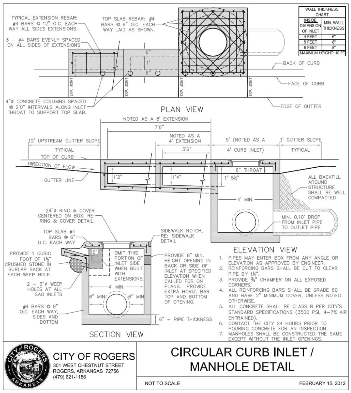
Section 1.02 Rectangular Curb Inlet/Manhole Detail
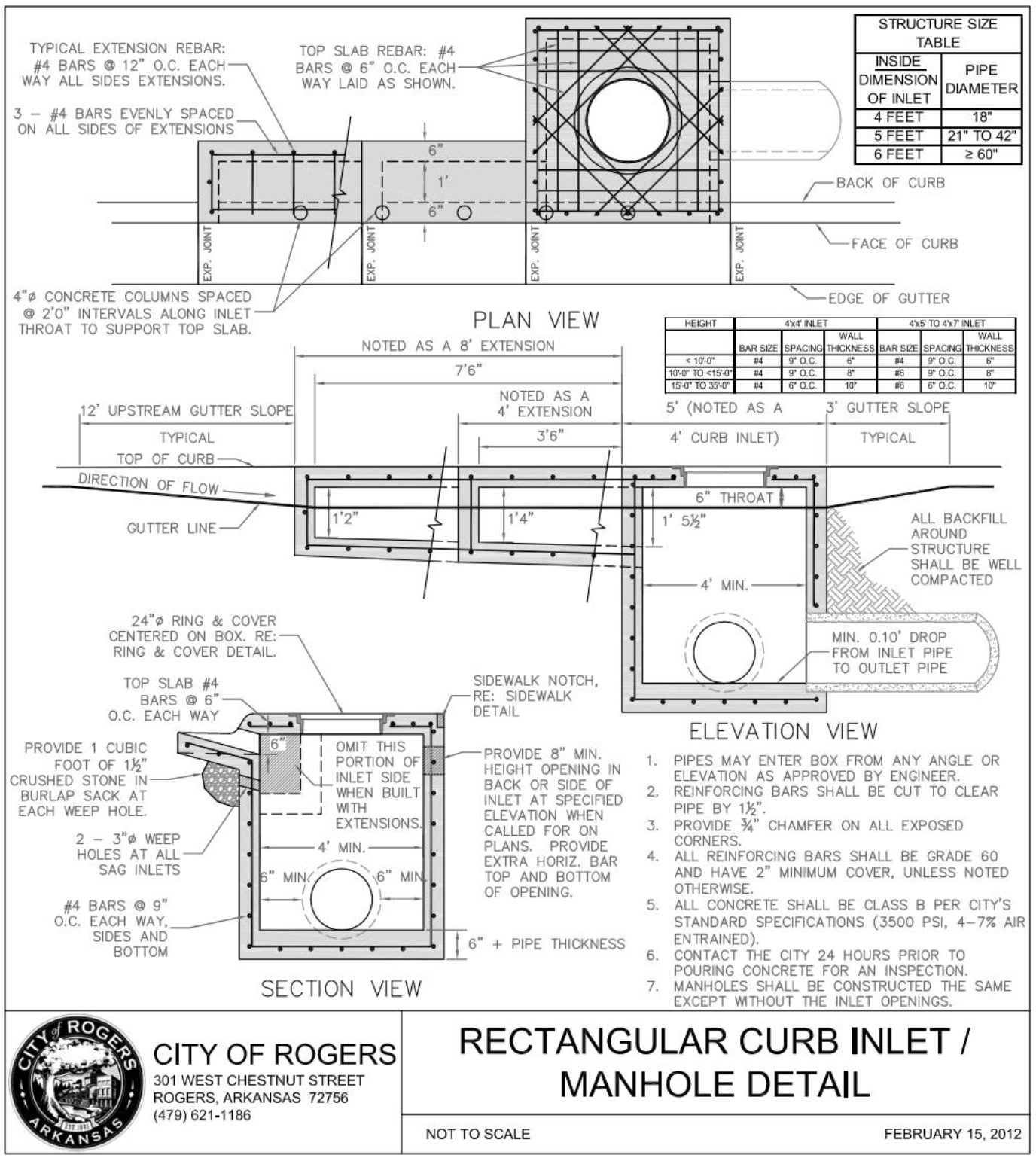
Section 1.03 Reverse Throat Inlet Detail
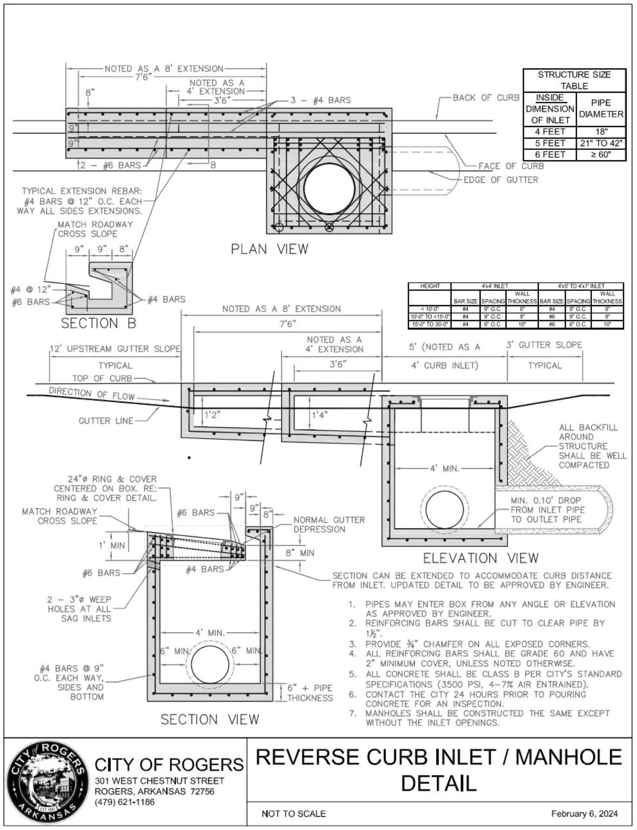
Section 1.04 Residential Driveway Detail
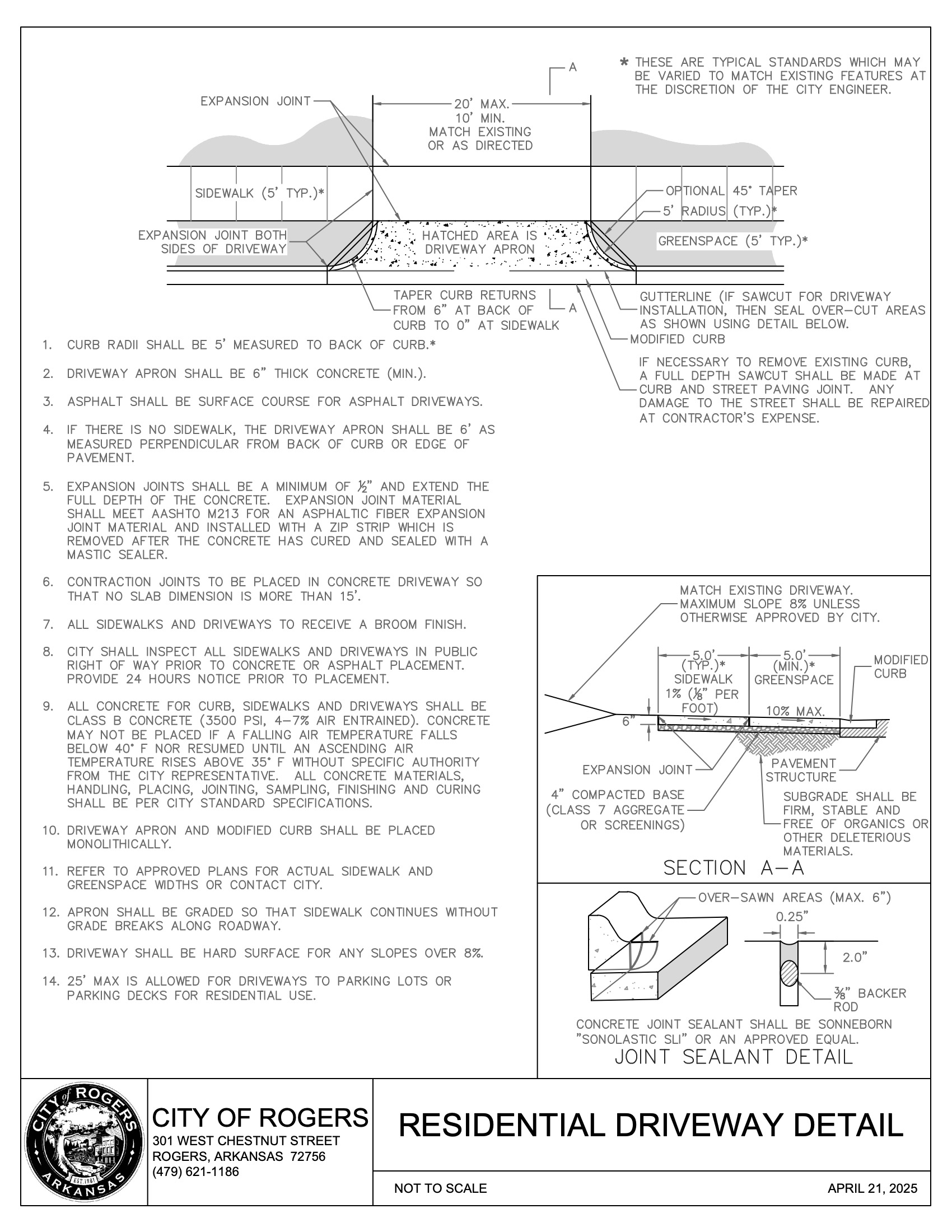
I.5 Commercial Driveway Detail
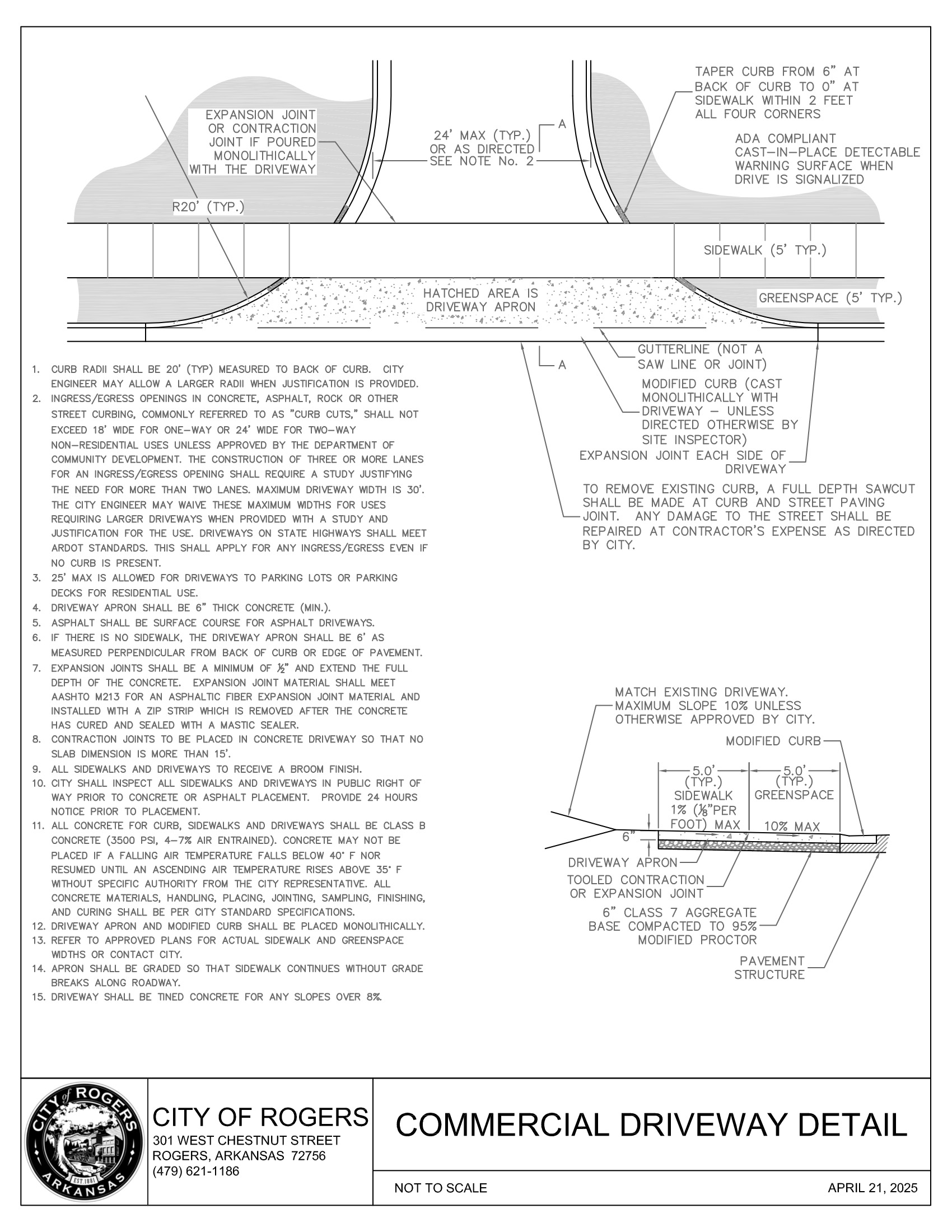
I.6 Sidewalk Detail
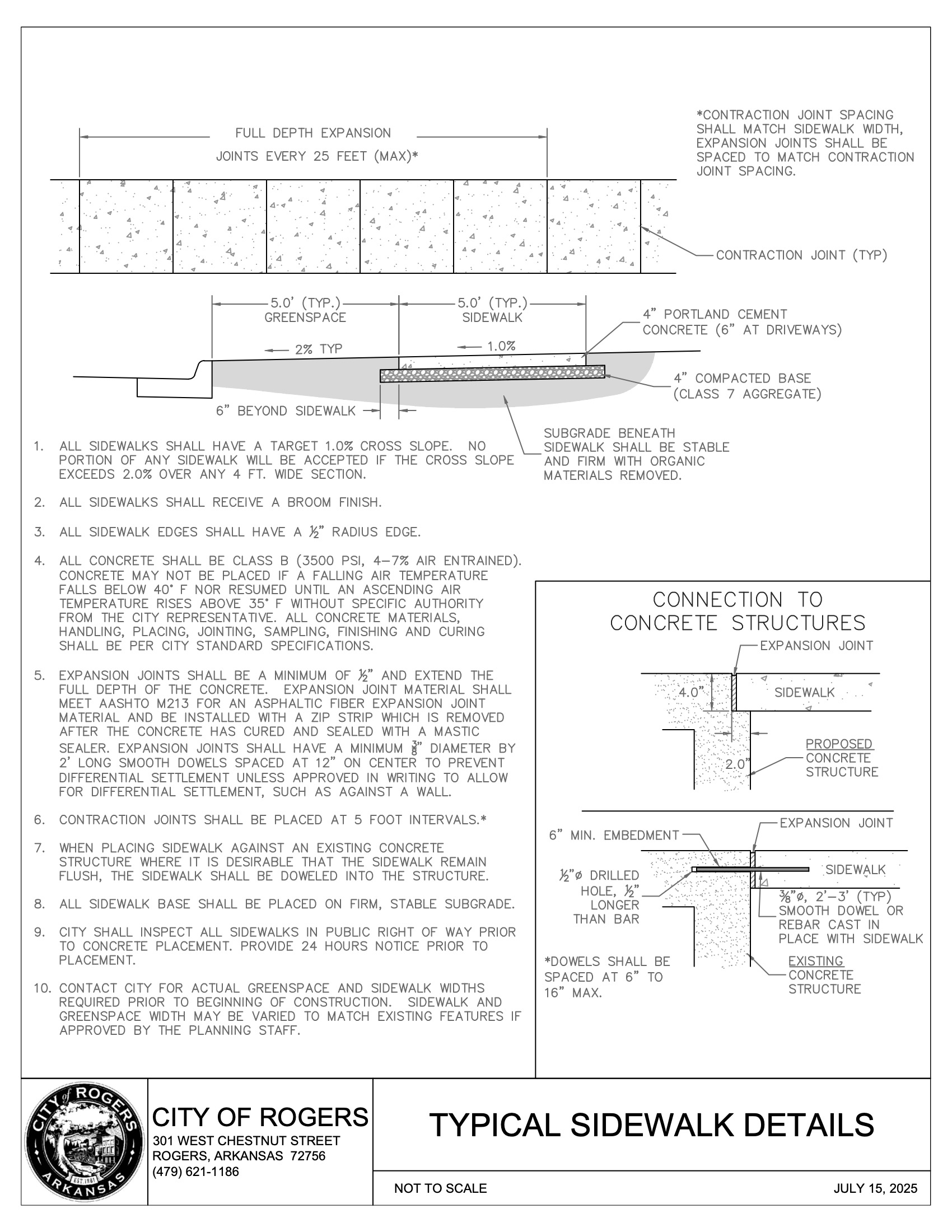
I.7 Crosswalk Detail
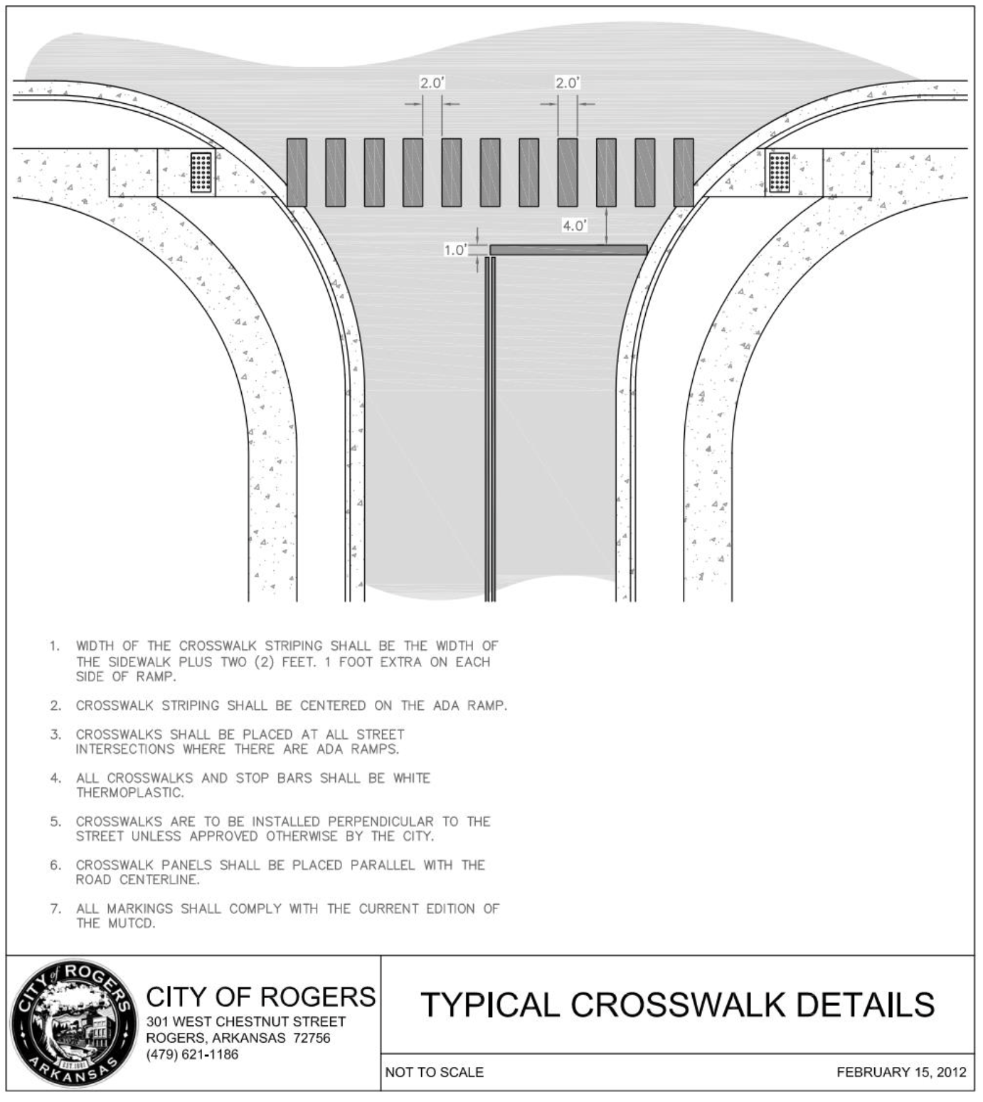
I.8 Curb and Gutter Detail
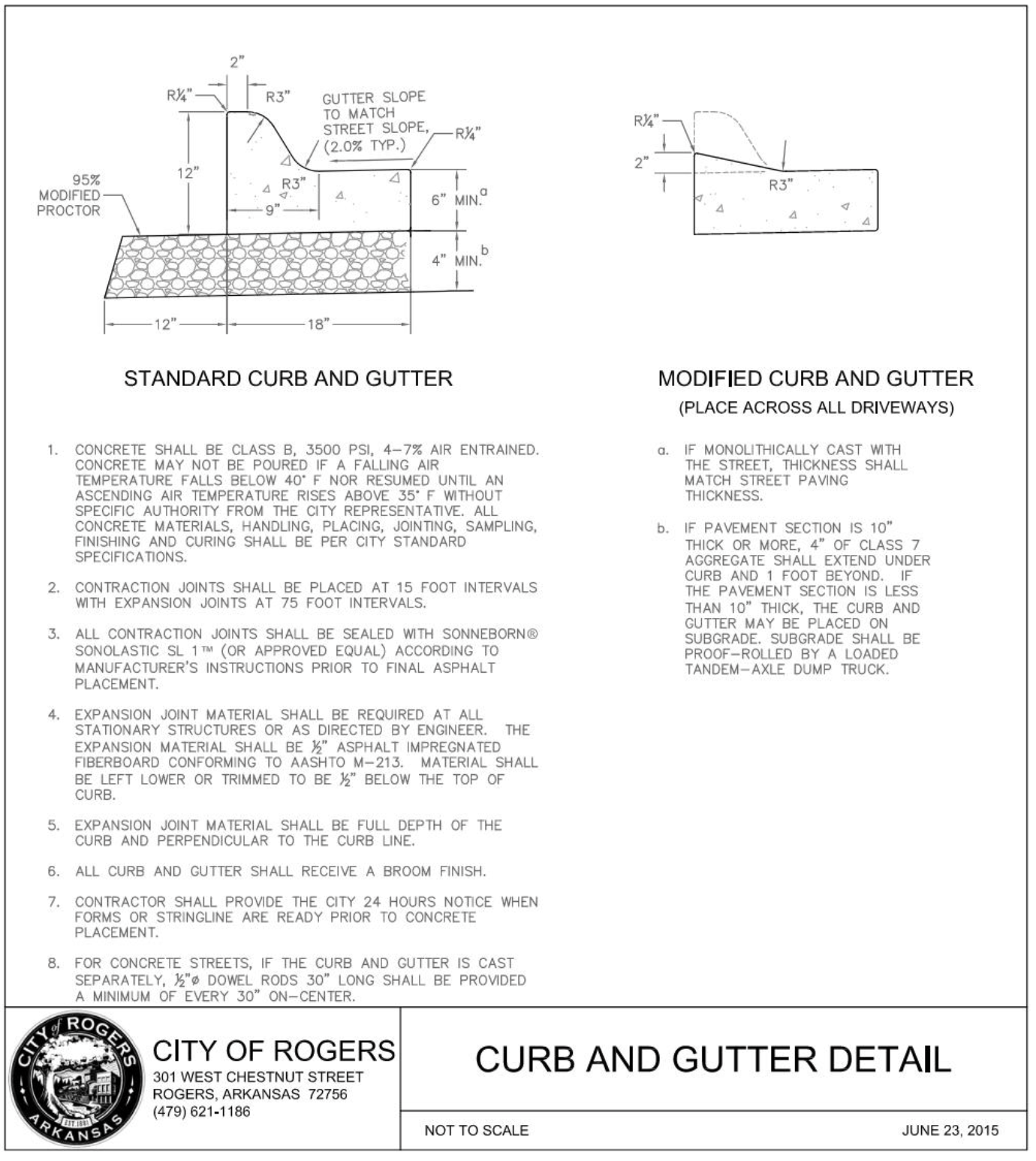
I.9 Perpendicular Curb Ramp Detail
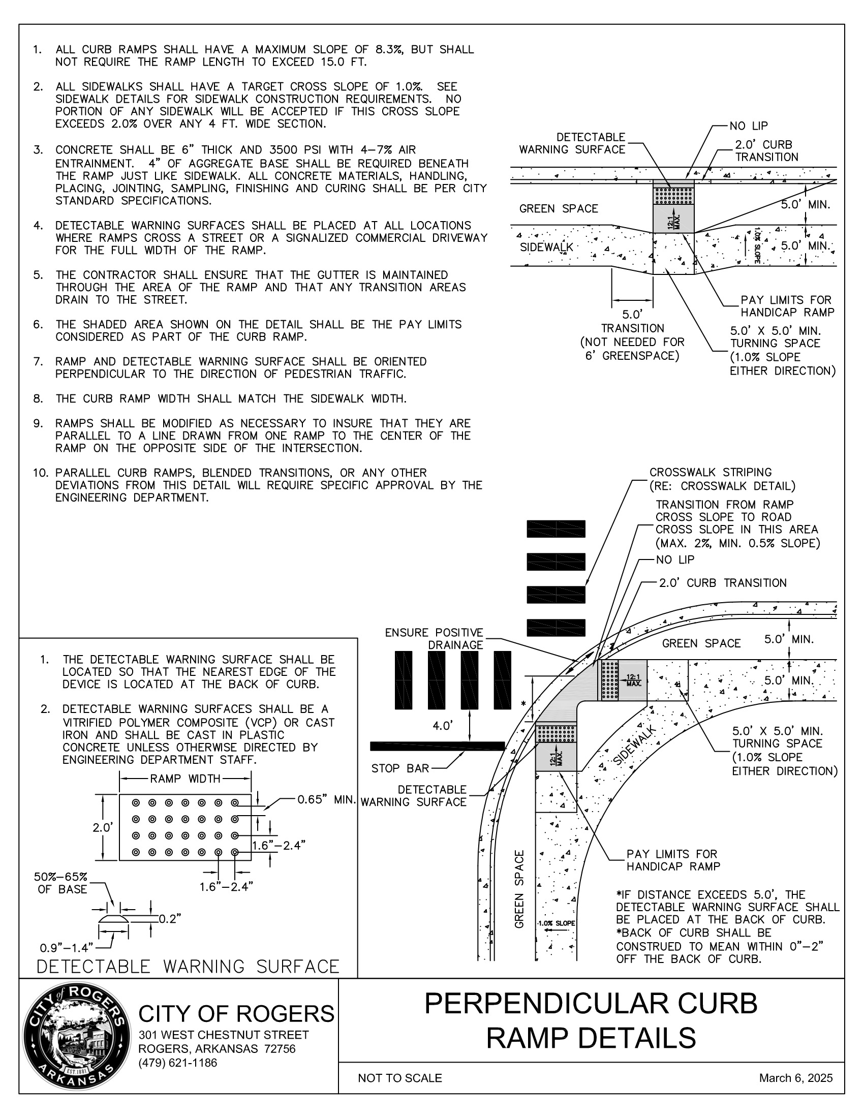
I.10 Manhole Ring and Cover Detail
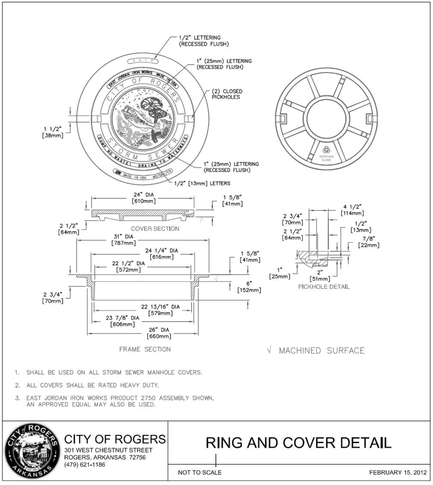
I.11 Bikeway Crossing Detail 1
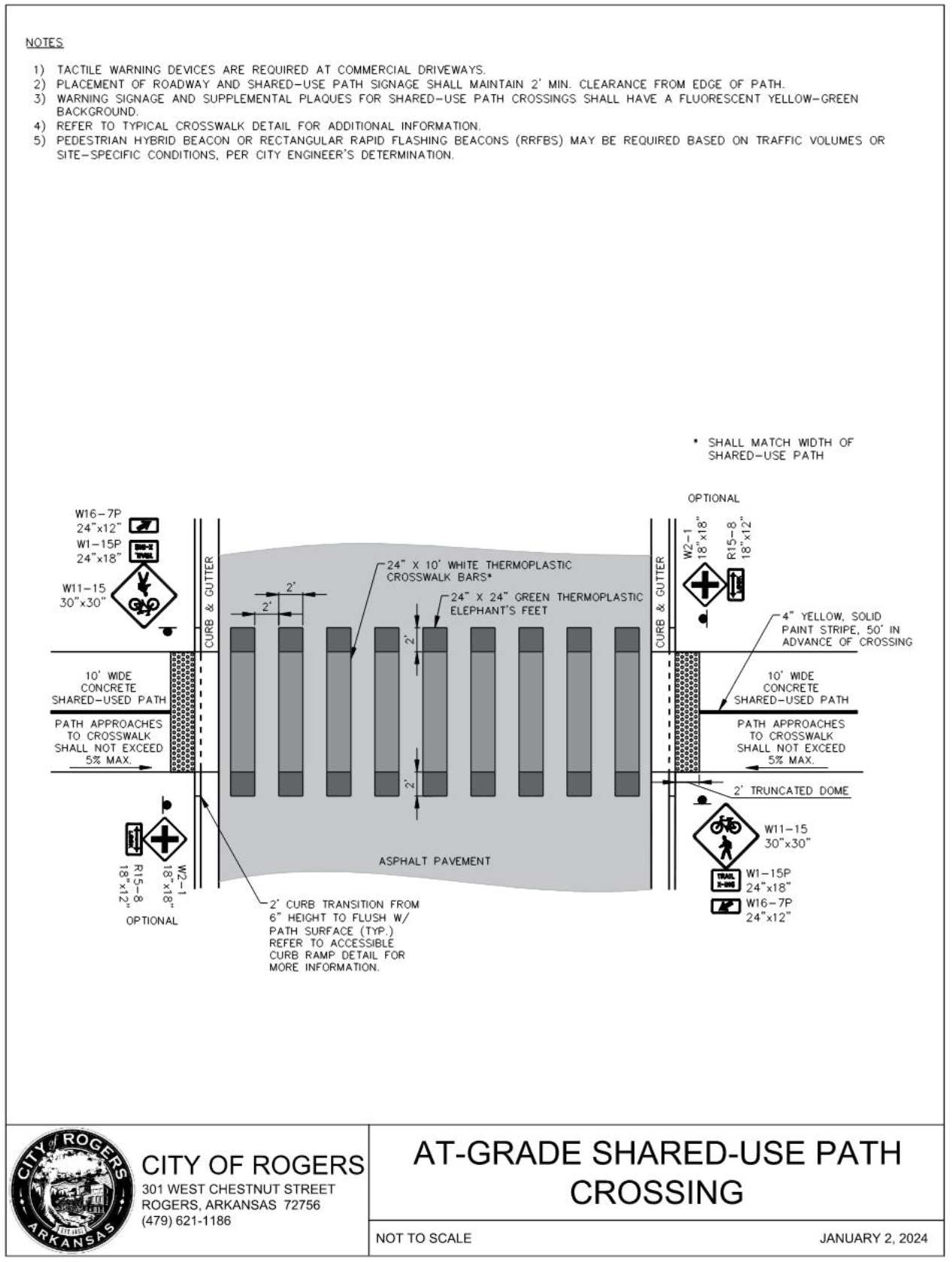
I.12 Bikeway Crossing Detail 2
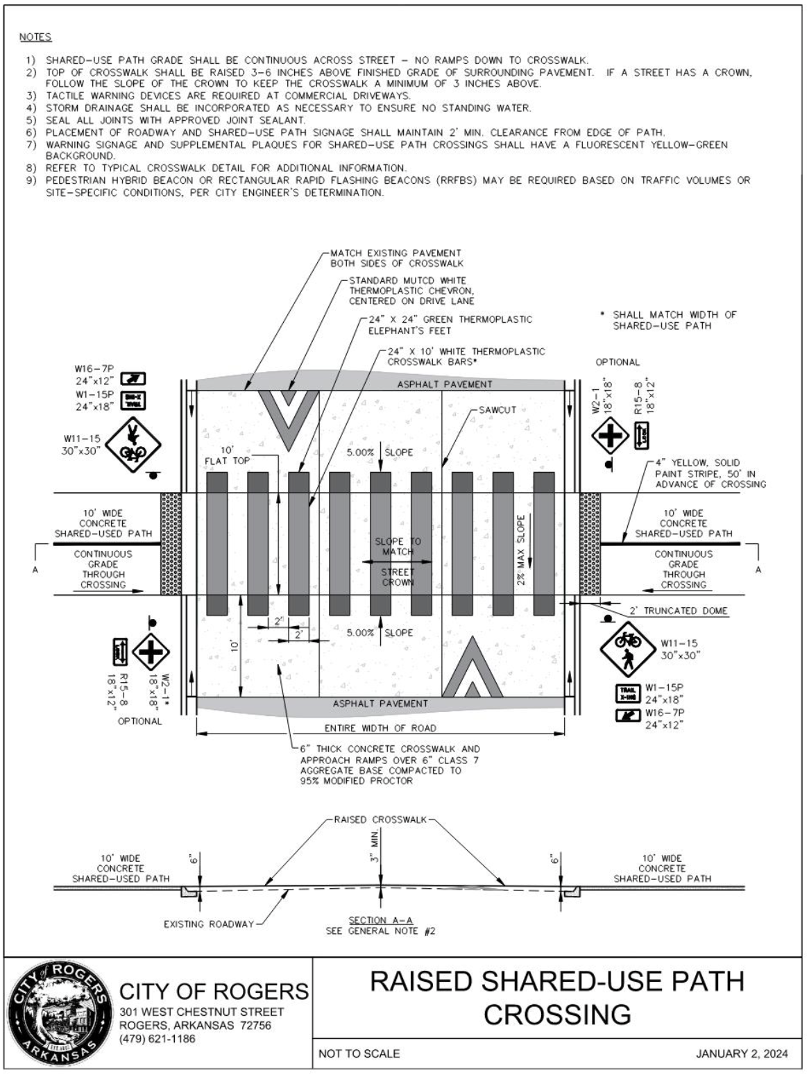
I.13 Roundabout Apron Detail
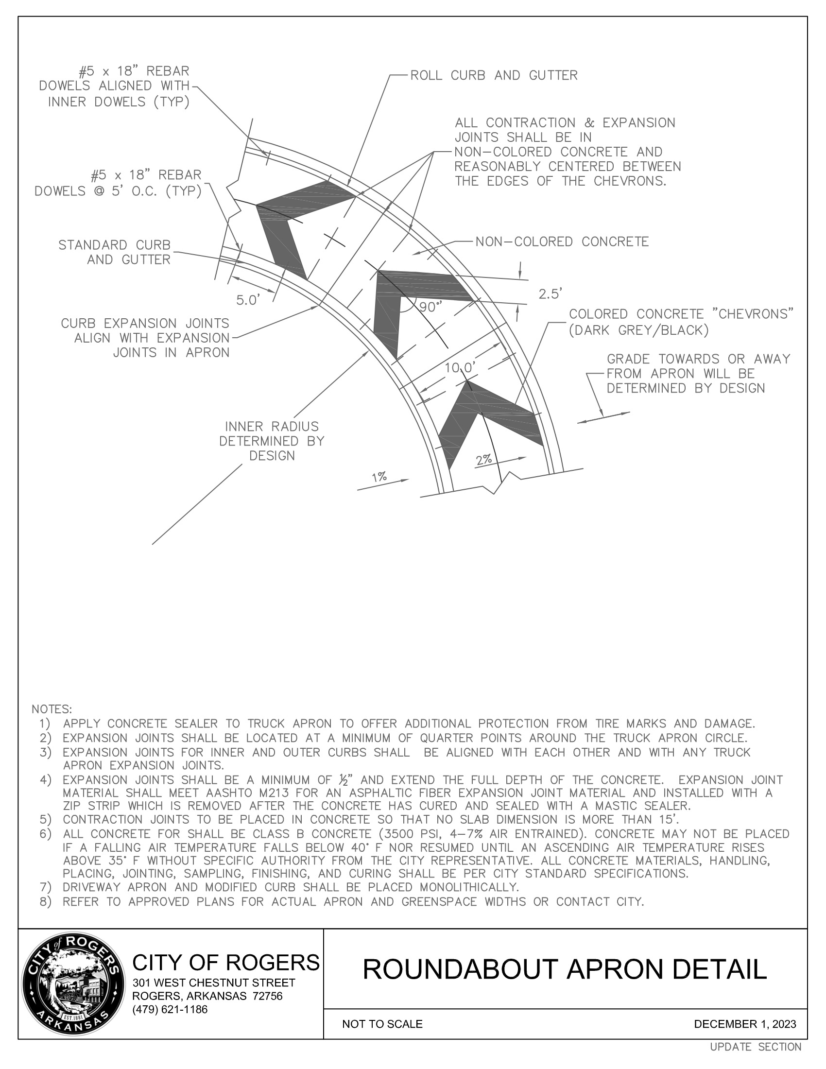
I.14 Sidewalk Closed Detail
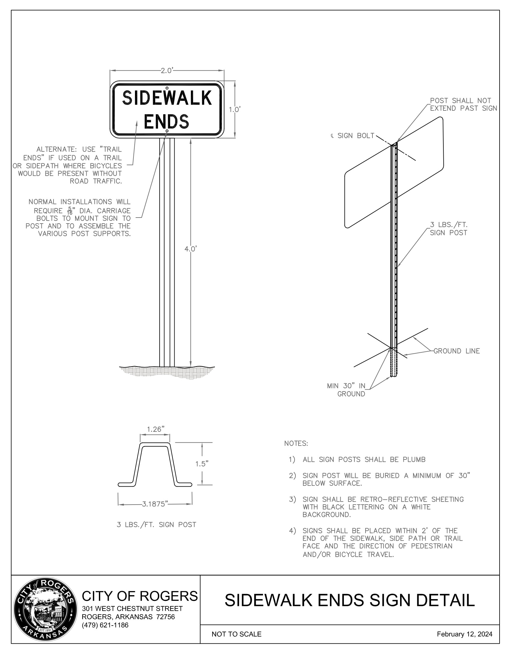
I.15 Future Street Extension Detail
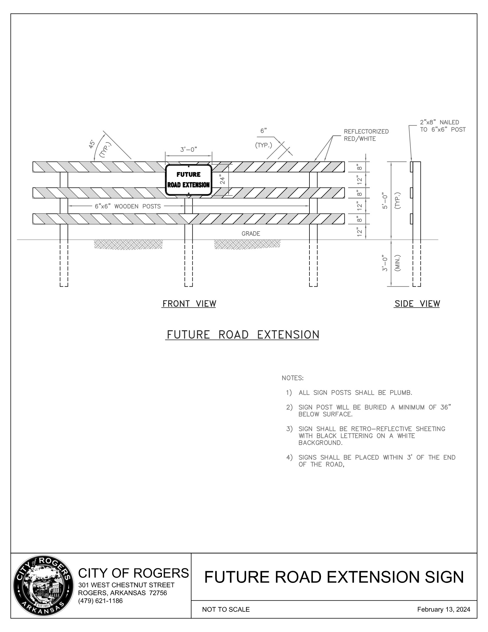
I.16 Cross Access Stub-out Signage
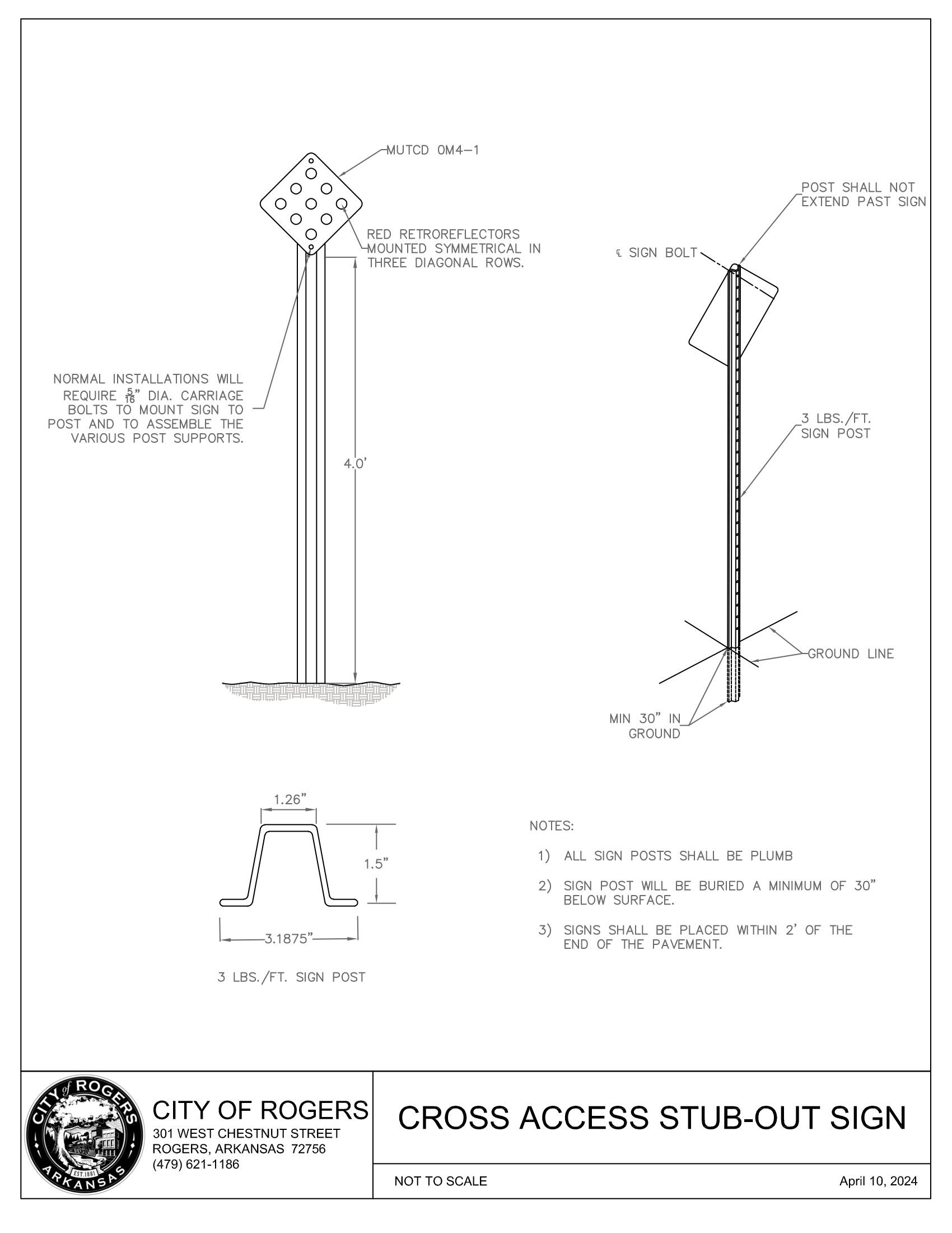
I.17 Tree Well Planting Detail 1
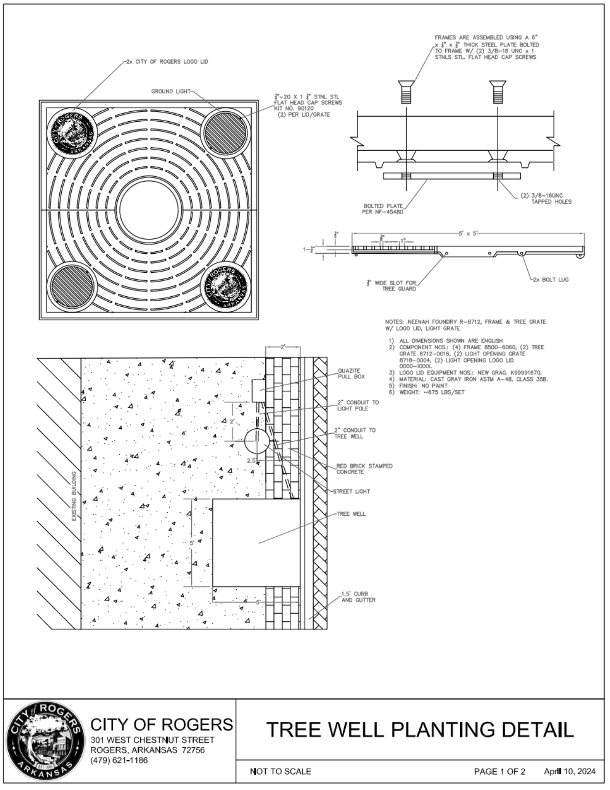
I.18 Tree Well Planting Detail 2
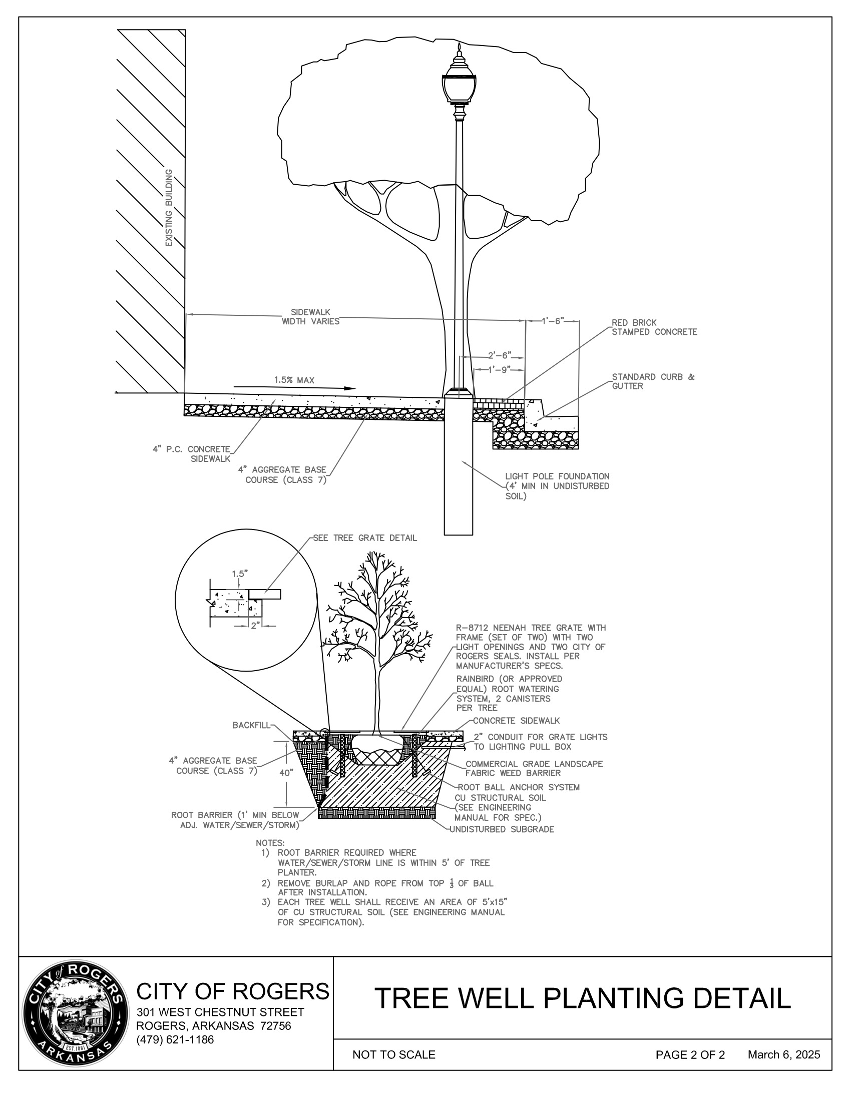
I.19 Pavement Repair Detail
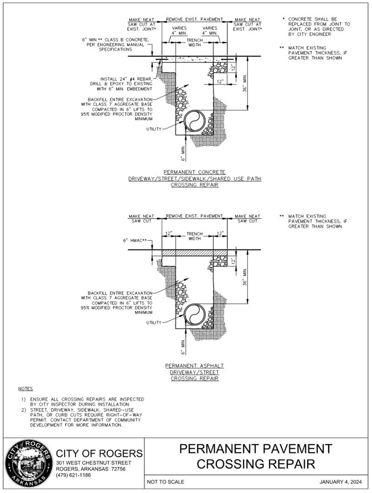
I.20 One Lane Trail Closure Detail
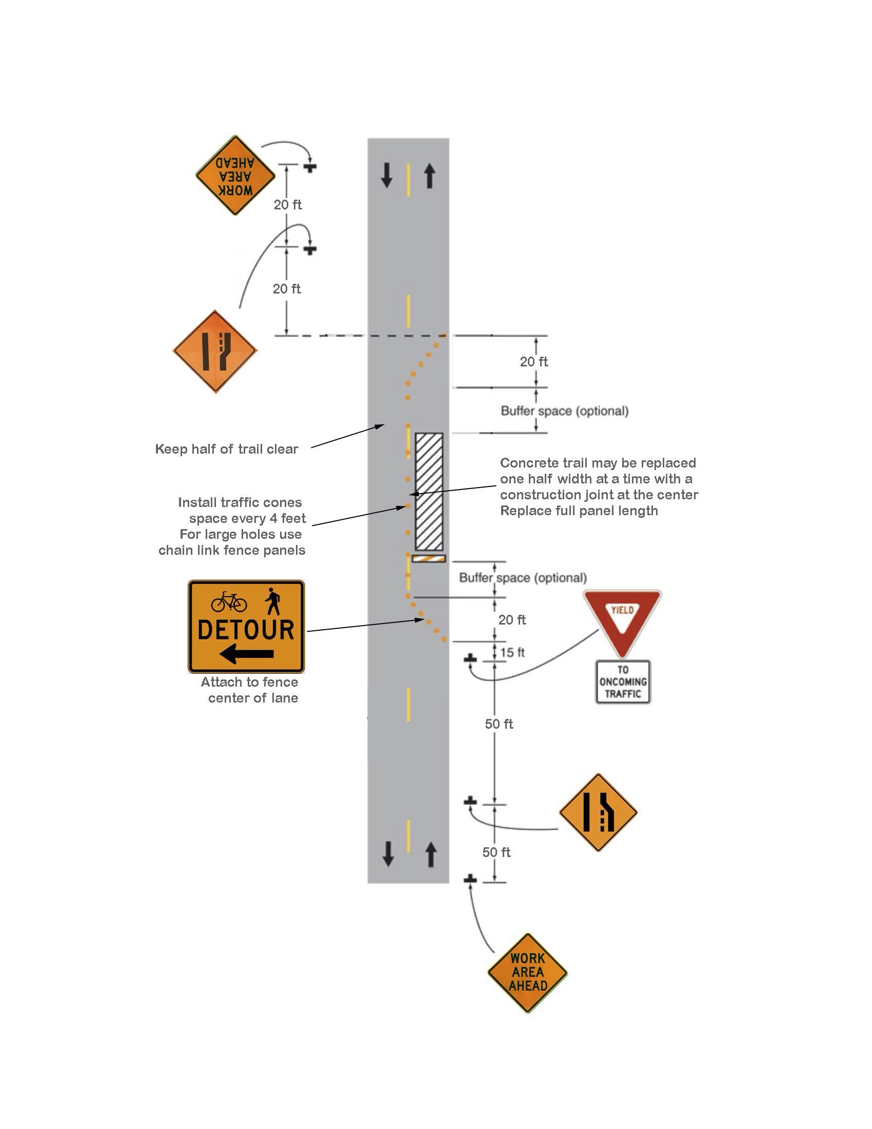
I.21 Multiuse Trail or Shared Use Path
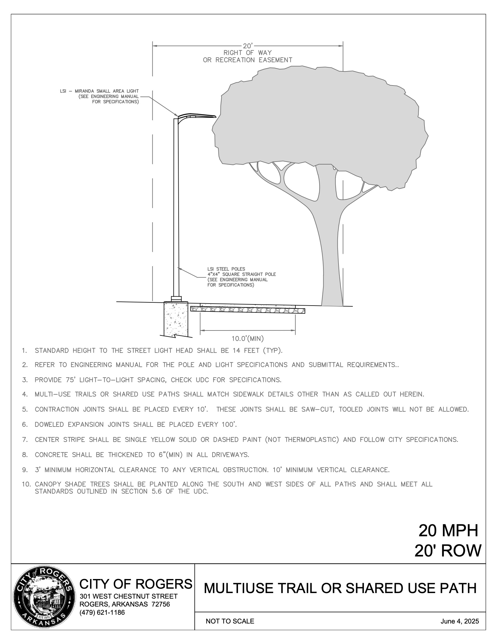
II.1 General outline of report.
- Table of contents.
- List of figures and tables.
- Traffic impact analysis background and requirements.
- Data sources.
- Introduction.
- Study area.
- Existing land use.
- Proposed development.
- (iii)Existing roadway conditions and traffic counts.
- Analysis.
- Trip generation.
- Trip distribution and trip assignment.
- (iii)Projected site turning movement counts.
- (iv)Projected traffic.
- Capacity analyses.
- Conclusions and recommendations.
- Appendix.
II.2 Maps and diagrams.
- Conditions maps and drawings.
- Location maps and site plans. 1, 2, 3
- Master street plan. 4
- (iii) Existing turning movement count diagram: a.m. peak hour. 5
- Existing turning movement count diagram: p.m. peak hour. 5
- Existing turning movement count diagram: peak period for site. 5
- (vi) Summary of existing/projected 24-hour volumes. 6
- Trip generation/trip distribution diagrams.
- Site trip distribution. 7, 8
- Boundary street projected turning movements: peak period 5 for site. 9
- Recommended site access configuration and roadway improvements.
- Diagram. 10, 11
II.3 Tables.
- Land use characteristics and total site trips generated. 12
- Site trips attracted from passing traffic (if applicable). 13
- Land use characteristics and internal/external site trip generated. 14
- Summary of capacity analyses. 15, 16, 17, 18
II.4 Conclusions and recommendations.
As a minimum, the TIA shall identify all geometric and operational improvements necessary to provide an acceptable LOS for facilities within the project site and/or along the boundary streets of the project site. Both on-site and off-site improvements must be evaluated. Priority should be given to beneficial off-system improvements as a means of minimizing the impact on the existing transportation system. Improvements that are to be considered for the purpose of mitigating less than an acceptable LOS shall include as a minimum: pavement widening, installation of turn lanes, installation of median islands, access control, installation of curbs and/or sidewalks, installation of traffic signalization, traffic signing, and/or pavement marking modifications.
II.5 Appendix.
Appendix documents shall be provided to the city at the time the TIA is submitted. The number of appendix documents to be submitted shall be identified at the time of the preliminary information meeting. At a minimum, the appendix shall contain:
- Summaries of turning movement counts.
- Summaries of 24-hour counts.
- Summaries of capacity analyses.
- All other data necessary to support findings and recommendations.
NOTES:
1. | Show pavement marking layout and lane usage for all boundary streets. Drawing must reflect driveway locations and roadway geometry within +/- one foot of actual location. |
|---|---|
2. | Show driveways and land uses on both sides of all boundary streets of the proposed site. |
3. | All driveways and intersecting streets that connect to a boundary street shall be illustrated in sufficient detail to serve the purpose of illustrating traffic function. At a minimum, this detail shall include all lane widths, traffic islands, medians, sidewalks, curbs, and traffic control devices. |
4. | At a minimum, the drawing shall encompass a minimum four-mile radius from the site and shall identify all roadways designated on the city master street plan, their corresponding designation, a legend identifying roadway classifications, and the approximate location of the proposed development. |
5. | Results of the turning movement count for each location shall be overlaid on top of the existing conditions layout. |
6. | Indicate existing and projected 24-hour volumes for all major roadways, as identified in the preliminary scoping meeting. Assumptions of growth rates for traffic demand and references shall be identified on this exhibit. |
7. | Indicate general directional distribution of trips to and from the development. |
8. | Indicate assignment/distribution of projected trips for the site, by movement, at each access point. |
9. | Indicate combined existing and site generated traffic and the site generated traffic volume for all movements at each intersection and/or driveway within the study area. |
10. | The diagram shall, as a minimum, indicate existing and proposed pavement marking layouts for all boundary streets, proposed modifications to existing and/or the installation of new traffic control devices, proposed on-site circulation, parking layout, pad locations, and any modifications necessary to address increases in traffic demand associated with the site development that result in significant reductions in operations. |
11. | Site plans for all commercial development, residential subdivisions, and multifamily dwellings on collector, minor arterial, and major arterial streets will be analyzed as part of the Traffic Impact Analysis for critical traffic conditions for both the initial opening and full development of the site. The Community Development Director may require ARDOT deceleration lanes for single and combined uses that generate driveway volumes (trip ends) of 300 or more vehicles in the peak hour, as determined using standard Institute of Transportation Engineers (ITE) trip generation rates for the subject land use(s). For additional development requiring a building permit, which would generate driveway volumes (trip ends) of 300 or more vehicles in the peak hour, the Community Development Director may also require the installation of an ARDOT-approved deceleration lane. Four hundred feet minimum spacing between drives, measured centerline to centerline or from the right-of-way intersecting lines of public streets to the centerline of a curb cut, is required when deceleration lanes designed in accordance with ARDOT are required. The decision to utilize acceleration/deceleration lanes shall be dependent on the context of the site and the presence of other modes of transportation. |
12. | The table shall include land use, gross leasable area (GLA), estimated daily trip generation estimates, and trip generation rates and estimates for weekday a.m., p.m., and for the development peak traffic period, broken down by entering and exiting trips. |
13. | The table shall include assumptions regarding percentage of passer-by traffic associated with each land use for the development, including proper source references. |
14. | The table shall include assumptions regarding percentage of internal/external capture traffic associated with each land use for the development, including proper source references. |
15. | The table shall summarize before and after conditions associated with level of service (LOS) for all study intersections and access drives adjacent to the site, whether signalized and unsignalized. Furthermore, existing and proposed conditions shall be summarized side-by-side for each peak period evaluated. All special evaluation conditions shall be appropriately footnoted. |
16. | Capacity analyses will be required for each roadway infrastructure improvement in order to verify the LOS associated with a given improvement. |
17. | Capacity analyses will follow the principles established in the latest edition of the Transportation Research Board's Highway Capacity Manual (HCM) unless otherwise directed by the city engineer. Capacity will be reported in quantitative terms as expressed in the HCM and in terms of traffic LOS. |
18. | Capacity analyses will include traffic queuing estimates for all critical applications where length of queues is a design parameter (e.g., auxiliary turn lanes, traffic gates, etc.). |
III.1 Stormwater structure as-built data should be provided in the form of GIS data (shapefile or geodatabase).
Stormwater as-built data may be provided in CAD format provided that the attribute data is fully defined as described below, or can be fully defined with an accompanying Excel workbook. In the case of point structures only, as-built data may be provided as an Excel workbook using the as-built Excel template discussed below if the data cannot be provided in GIS format. In all cases the data structure will correspond to the definitions provided below and photographic images will be provided as a zip archive. In summary:
- Structures/Pipe As-Builts provided in GIS format + Photos in .zip archive,
Or - Structures/Pipe As-Builts provided in fully-defined CAD format + Photos in .zip archive,
Or - Structures/Pipe As-Builts provided in CAD format + Excel workbook + Photos in .zip archive,
Or - Structures (only) provided in Excel workbook + Photos in .ZIP archive.
- Supporting documentation is available for download at <location>. Available supporting documents include an Excel as-built template, example shapefiles and geodatabase, and a Data Dictionary.
- Attribute Table headers are shown in Table 1 and Table 2. The Structures Attribute Table Header is used for all point structures (structures such as headwalls, junction boxes, inlets, grated inlets, detention outfalls, flared end sections, etc.), not including pipes. The Pipes Attribute Table Header is used for linear features (pipes, concrete ditches (conditch), earthen ditches, culverts, etc.).
- Except as noted, all values are required. Items below marked with an asterisk * are limited to values in the worksheet dropdowns list. Items shown in (parentheses) are optional. In cases where dropdown list item “Other” is selected, details shall be provided in data field OTHER.
- Refer to the Data Dictionary for full list of feature attributes, descriptions, formats and units.
- Digital photograph(s) of point structures or linear structure endpoints are required. Photos will be documented in the attribute data by providing the filename (including file extension), date shot, and shot_by. Image file names shall be in the format:
CWNUMBER_FEATURENAME_FEATURE_ID_n.ext
where:
CWNUMBER = CityWorks Permit Number (e.g. LSDP23-0001, MINORSB24-9999, PL20201234, etc.)
FEATURENAME = FEAT_NAME as defined in Data Dictionary
FEATURE_ID = FEAT_ID as defined in Data Dictionary
n = numerical identifier indicating photo in series
ext = image file format extension
Example: LSDP23-001_PipeABC_1234_3.png
…indicating a photo for CityWorks project LSDP23-001 for feature with name “PipeABC” and Feature_ID 1234, the third picture of this item, in PNG format.
Provide image files as external data in a zip archive format.
Table 3.03A - Street Geometry
Design Element | Alley | Minor | Collector | Arterial |
|---|---|---|---|---|
Design Speed (mph) | 20 | 25 | 35-40 | |
Minimum ROW Width (ft)1 | 20-30 | 50-70 | 80 | 90-110 |
Minimum Fore/Back slope | 3:1/3:1 | |||
Stopping Sight Distance (ft) | 125 | 150 | 250 | |
Intersection to Curb Cut/Drive (ft)2 | 20 | 40 | 150 | 250 |
Minimum Horizontal Radius at Centerline (ft) | 110 | 200 | 510 | |
Maximum Superelevation (%)2 | NA | 4 | 4 | |
Minimum Horizontal Tangent between curves or at intersections (ft) | 50 | 100 | 300 | |
Maximum Vertical Grade (%)4 | 10 | 8 | 8 | |
Minimum Vertical Grade (%) | 0.5 | 0.5 | 0.5 | |
Vertical Curves | Required at any grade change ≥1.0% | |||
Minimum K-Value Crest | 7 | 12 | 29 | |
Minimum K-Value Sag | 17 | 26 | 49 | |
Minimum Vertical Clearance – Road (ft) | 16.5 | 16.5 | 16.5 | 16.5 |
Minimum Vertical Clearance – Bicycle Facility (ft) | 10 | 10 | 10 | |
Pavement Cross-slope (%)5 | 1.5-4 | 2-4 | 2-4 | 2-4 |
1. ROW width may vary from the typical shown. 2. Measured from centerline of driveway to ROW of the intersecting street. 3. Superelevations greater than 2% require City Engineer approval. 4. Grades over 8% require approval by City Engineer. 5. Cross-slopes over 2% require approval by City Engineer and shall not be used where it would violate PROWAG. | ||||
Table 3.03B - Number of Curb Cuts
Length of Street Frontage | Maximum Number of Curb Cuts |
|---|---|
600 feet or less | 1 |
601-1,500 feet | 2 |
More than 1,500 feet | 3 |
Table 3.03C - Distance between Curb Cuts
Travel Speed Permitted | Minimum Distance Between Curb Cuts |
|---|---|
30 mph or less | 100 feet* |
35 mph | 150 feet |
40 mph | 200 feet |
45 mph | 250 feet |
50 mph | 300 feet |
55 mph | 350 feet |
| * Residential lots on minor streets may be closer than this. | |
Exhibit 3.03 - Franchised Electric Utility Service Area Boundary
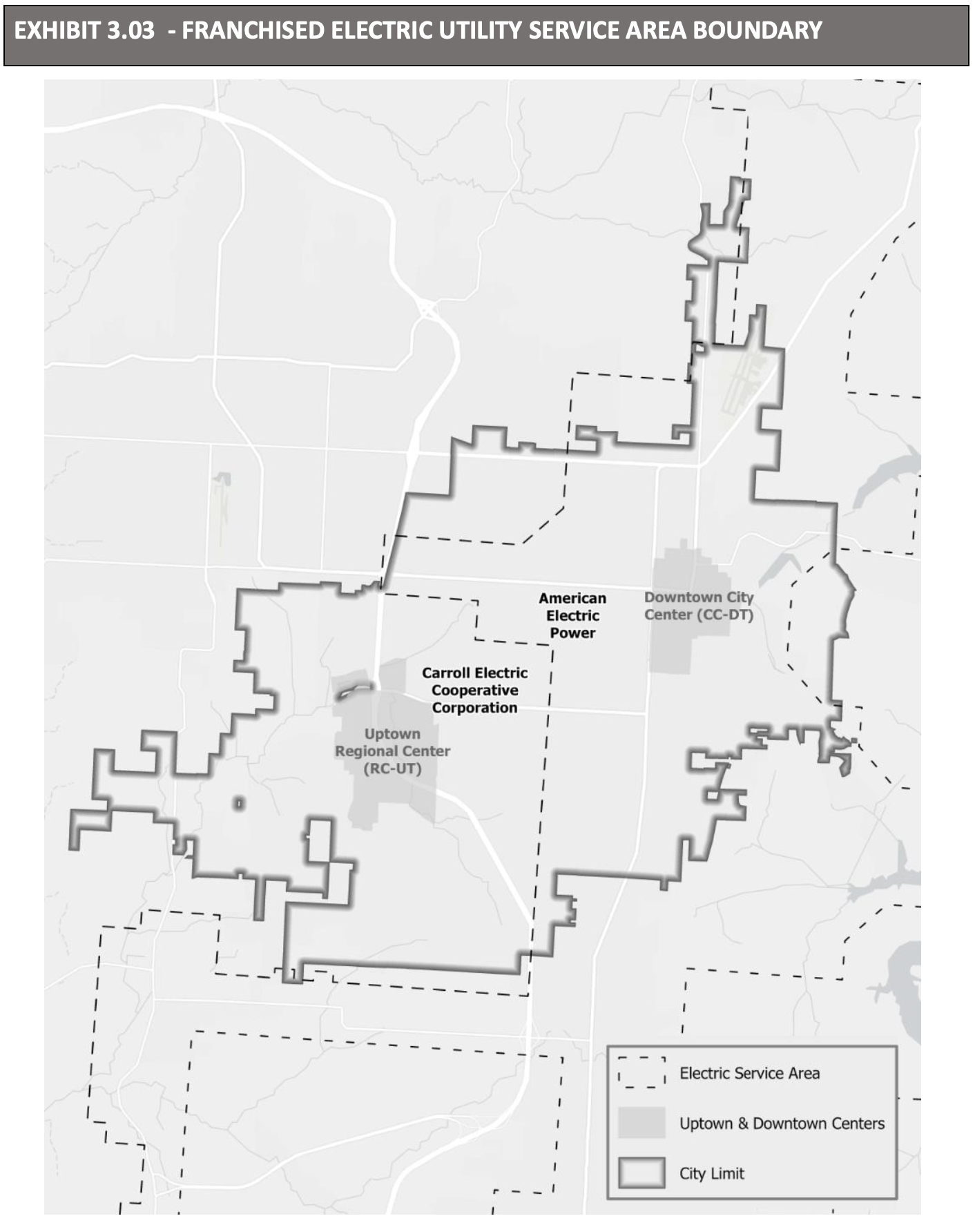
(Ord 25-35, 7-8-2025)