
Beaufort County Unincorporated
City Zoning Code
City Zoning Code
Appendix D
- Technical Manual
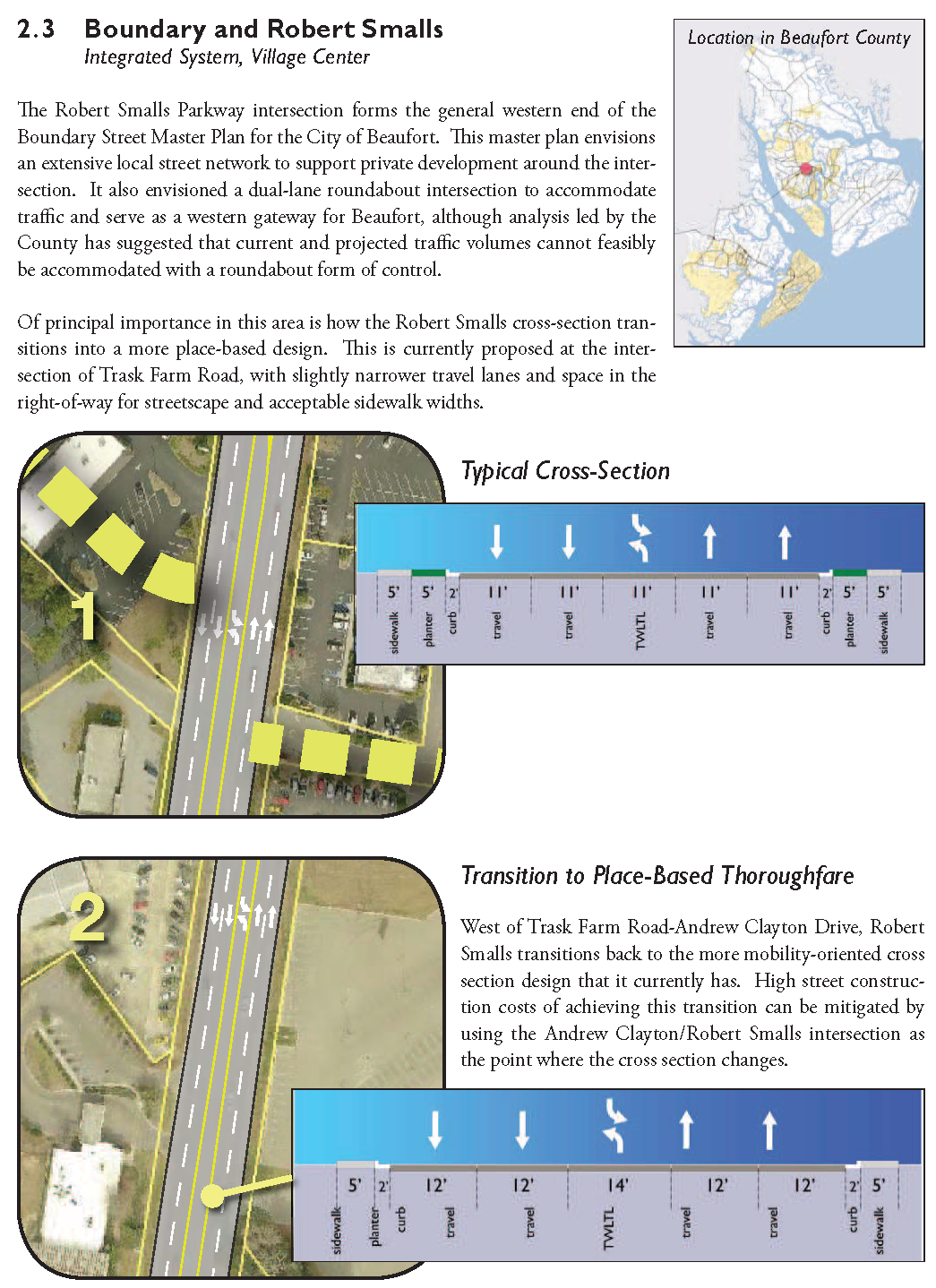
The end goal of this form-based code effort and its street design component is the furtherance of a walkable Beaufort County. Many physical characteristics, such as wide lanes, multiple lanes, wide shoulders and clear vistas, can conspire to make a street or road unwalkable. However, the decisions that lead to these characteristics are often made long before the design process begins in earnest. It is, therefore, important to consider briefly how transportation is planned and managed and what might occur throughout this process to achieve the desired outcome of walkability.
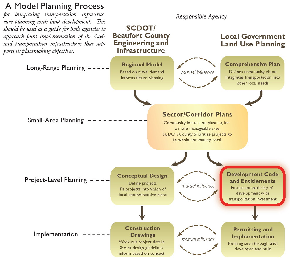
The process defined here suggests a way partner agencies can jointly plan for integrated transportation and land use in a way that allows them to respond to their agency mandates as well as understanding the needs and concerns of their partner agencies. The diagram below illustrates a series of steps, each corresponding to a level of detail in the planning process, and how responsibilities could be met individually (though with acknowledgement of the mutual influence that each agency has on the other) and where the planning effort is best made when groups work together. Each of these levels in the diagram is discussed at greater length in the following sections, detailing strategic tools that each partner has in working together in transportation implementation.
1.1 - Street Design Resources
The design and construction of streets and roads is governed by a series of technical documents which are little understood outside the transportation engineering community. This chapter seeks to explain those guiding documents and describe the basis within them for the street recommendations for Beaufort County.
1.1.1
AASHTO Green Book: Every state in the U.S. as well as most counties and cities have adopted A Policy on Geometric Design of Highways and Streets by the American Association of State Highway and Transportation Officials (AASHTO). This publication, nicknamed "The Green Book," provides guidance on most design issues related to the engineering of streets and roads. Design guidance published in the AASHTO Green Book reflects the consensus of AASHTO's member departments regarding what constitutes good design practice nationally. In arriving at a consensus, AASHTO recognizes that each region or state has different conditions, constraints, and needs. While the book allows substantial flexibility based on the judgment of designers based on local conditions, this flexibility is often misunderstood by practitioners. As is noted in the foreword of the Green Book, "sufficient flexibility is permitted to encourage independent design tailored to particular situations."
For many agencies, the design criteria in the AASHTO Green Book can be a starting point or benchmark. Other published design criteria, such as that published by the Institute of Transportation Engineers or NCHRP, may also be of use. The Green Book is thus a guide, a reference, and a basis for the development of an agency's guidelines. Terrain, climate, culture, values, and driving habits differ across the nation; what is good and acceptable in one location may not be satisfactory or practical in another. For example, AASHTO presents design criteria for horizontal curves with a full range of possible design values for maximum super elevation. The Green Book does not prescribe or favor one set of values over another. Rather, States are free to select one or more "maximum super elevation" values based on their climate, design preferences, or other considerations, and to design curves in their state accordingly. Thus, neighboring states may design curves different from each other, yet both would be following the AASHTO "policy."
1.1.2
AASHTO Flexibility Guide: As a companion to the Green Book, AASHTO has developed a guide to "Flexibility in Highway Design", describing the flexibility available to implementation agencies. This book spells out in more explicit detail some of the allowable practices that many communities believe will improve safety, livability and quality of life.
1.1.3
ITE Walkable Thoroughfares Guide: As a response to communities that feel a lack of transportation agency flexibility has damaged their walking environments - particularly on arterial roadways - the Institute of Transportation Engineers developed an manual describing the design of these facilities. This book provides even more clarity regarding some design issues for which imprecise or conflicting guidance appears in the AASHTO books. It is, therefore, a useful companion document. Some details of the guidance of these three sources are described in Section 3.
1.2 - The Planning Process
1.2.1
Long-Range Planning: Long-range planning is a first step that reflects each agency's responsibilities: SCDOT and County Transportation to planning for transportation and regional mobility, and local planning departments to planning for urban growth, land development and neighborhoods. It is important to remember that while this is the first step in the process, specific expectations for projects should not be defined here. In transportation planning, the regional model identifies deficiencies in capacity, but it is often assumed that this deficiency must be addressed through roadway widening. In other words, a particular model result takes on a life of its own and acts to predetermine the outcome of a project.
It is well understood that the regional transportation model draws on assumptions of land use in future years to be a reliable indicator of travel demand. The long-range planning step for Beaufort County must be based on a commitment from the relevant local government to follow its program for how to grow and develop: In other words, local governments must make land use plans and honor them as current development occurs. Likewise, planning for community growth and maturity means that the land use agency must understand the potential impacts of mobility needs, which is why a jointly accepted definition of corridors to which SCDOT and the County can commit should be set early in the planning process.
While this long-range process is important, it does not constitute the full degree of planning required for implementation. According to the ITE Walkable Thoroughfares Manual, "none of these definitions sufficiently describes urban context at a level of detail that relates the context to the transportation system or the thoroughfare design."
1.2.2
Small-Area Planning: Once these long-range planning documents are developed and adopted, both agencies should collaborate on a geographic level focused on smaller areas. This is intended to break a local government's jurisdiction down into manageable sections that allow it to begin considering more detailed land form and use concerns. At the same time, these allow transportation agencies to identify where the planning needs demonstrated in its regional travel demand model correspond with the specific geographic areas of the sector plans. It is here that transportation projects should begin to take shape, as transportation professionals, working with comprehensive planners in developing the area plan, better understand the implications of project ideas on the community. Unfortunately, this level of the process is not ever undertaken in many communities causing projects to jump from a broad regional scale into design without fully considering the impacts. Bridging the gap between the identification of broad area deficiencies and the development of final solutions is perhaps the most important step in public transportation planning, but it is a process that is often filled with short-cuts and which too often occurs behind closed doors. These tactics should be avoided.
To that end, area plans should be at the heart of the joint planning process in that they allow both the local government and the transportation agencies to understand the other's long-term needs and priorities. The regional transportation model may identify general capacity deficiencies and point out future corridors where roadway expansion would be necessary, but the sector plan allows everyone to better gauge the "fit" of these projects in the communities they will be serving and to decide on the most sustainable, viable transportation investment to make there. These are plans that both the transportation agency and the relevant local government(s) for an area will adopt.
The small area planning process is also where street master plans are defined. Rather than assessing this level of detail at the county-wide comprehensive plan level, local governments tie the need and particular opportunities for connectivity to other concerns in that community. Working with the planning department, the transportation agency can assess the places where its network can be augmented and how transportation concerns beyond street alignments and width - such as block dimensions, street spacing and potential signal locations - should be accommodated.
Just as not all projects are the same, all planning efforts will not be the same. If a labor intensive, highly involved intermediate planning process were undertaken for every transportation project, agency staffs and budgets would be quickly overwhelmed. The key, the, is to find some means to identify the projects that need more attention. There are several cues that can help to paint this picture:
•
The Political Landscape - It must certainly be conceded that political realities can, at times, drive controversies surrounding a given project.
•
Degree of Previous Planning or Existing Consensus - There are times when it is clear to all that a project is needed, accepted and can move forward without controversy or acrimony.
•
Detailed Community Assessment (X-Rays) - There are some basic geographic and special analyses that can be quickly undertaken to identify the need for a more extensive public process. Among the significant elements that can become apparent via use of these X-rays are schools, parks and other community facilities; single-family residential uses; and availability of and opportunities for street network.
•
Pressure or Opportunity for Land Use Change - If we know, suspect or want land use to change, we can be sure we have opportunities and perhaps responsibilities beyond the street right-of-way.
1.2.3
Project-Level Planning: This step of the process is perhaps closest to the current nature of collaboration among transportation agencies and planning departments. It allows the more direct partnership in developing the sector plans to be carried out to the level of project development and land development regulations. It is at this level that the local government codifies the sector plan's land form and community character principles and where the application of the street guidelines in this manual takes place.
1.2.4
Implementation: This is the final process step, comprising the day-to-day functions of each of the agencies, though allowing for mutual input as needed, especially in coordinating desired street design with such development concerns as access. As illustrated in the diagram, the land-use planning agency and transportation agency are primarily working on their own, though the larger collaboration from earlier levels of discussion should help each understand the needs of this level of permitting in carrying out the larger vision.
1.3 - Preserving Mobility
While the goal of walkable streets within character areas is one that most stakeholders can probably agree on, one of the primary concerns of both SCDOT and Beaufort County's Public Works Department is mobility and preserving vehicle level of service throughout the County. It is important to bear in mind, however, that vehicular level-of-service focuses solely on the comfort of vehicular travel on a corridor. This metric does not take into account community character, pedestrian safety or any other factors that might be important to an individual community. Often, a good vehicular level-of-service is inversely related to the quality of travel for non-motorized users. An analysis focused solely on vehicular level-of-service tends to produce investments that cater solely to vehicular travel, such as widening and grade separation.
Thus, it becomes apparent that the travel demand model standing alone will not help Beaufort County to help create walkable communities. Broadening the tools of analysis to include other community considerations is one important step towards developing a multi-modal transportation network. The following subsections detail considerations in achieving a more holistic level of analysis.
1.3.1
Functional Classification and Context: The Federal Highway Administration's (FHWA) definition of functional classification of streets is based on a series of street types serving particular functions. It rests on an underlying recognition that travel, in general or for a particular trip, will not use only one of these types but rather a combination of them. The FHWA Functional Classification Guidelines state that "functional classification is the process by which streets and highways are grouped into classes, or systems, according to the character of service they are intended to provide. Basic to this process is the recognition that individual roads and streets do not serve travel independently in any major way. Rather, most travel involves movement through a network of roads." As such, it is important that each road be understood in terms of what role it serves in this transportation need: Whether it is a larger street or highway based on moving larger volumes of traffic long distances, or a more local street that provides property access. To that end, this Technical Manual uses the FHWA terminology of arterials, collectors, and local streets to describe street types that emphasize mobility, emphasize access, or combine the functions of the two.
However, the guidance provided in this document is based on making street design decisions to best respond to multiple users. This suggests that the traffic- and vehicle-oriented concerns of the conventional functional classification typology can be augmented with other needs to equip the street designer to create livable streets. The reason the guide exists is to provide a basis in thinking for making these decisions appropriately, not simply prescribing sets of dimensions and standards that are expected to apply universally. Emerging thought in street and road design in the last two decades has greatly emphasized flexibility as a key to meeting needs while minimizing impact, a concept explored in publications by both FHWA (Flexibility in Highway Design) and by AASHTO, the American Association of State Highway and Transportation Officials (A Guide for Achieving Flexibility in Highway Design). With this in mind, this Technical Manual uses functional classification as a basis for street type definition, but introduces a set of design factors that help the designer better understand the needs of the street, explained in the following section.
A major compliment to the emerging thought on livable street design is the notion of giving attention to street context, suggesting that it is not only the needs within the right-of-way that shape a street's design but also the needs of the surrounding environment, built or natural. Basic examples of this idea in practice are widely familiar and recognizable: Small-town main streets often feature on-street parking so that commercial businesses have a way of accommodating driving customers; city downtown streets feature wide sidewalks to accommodate the many pedestrians making short trips on foot from one destination to another.
1.3.2
Speed: Vehicle levels of service should be weighted against other community goals. It does the community no good if the solution is worse than the problem. The safety of pedestrians must be a priority within the character areas. Statistics are clear regarding the impact of vehicle speeds on pedestrian safety, as illustrated in the table to the right. Vehicle speeds around 30 miles per hour or less are more compatible with pedestrian environments. Adopting more compatible speeds in the areas of desired walkability does not necessarily degrade vehicle capacity. The Highway Capacity Manual indicates that density of vehicles on a roadway is optimized at a particular speed, and that this intersection of vehicle density and speed is the maximum flow the roadway can accommodate. While this is optimal speed likely to vary based on the roadway type (expressways, for example, have fewer traffic control points than urban streets and thus are likely to see higher speeds overall), it is important for it to be compatible with the desired environment. The key is to identify the speed where pedestrian comfort, vehicle capacity and satisfaction of travel time experience are best accommodated.
Source: National Highway Traffic Safety Administration, Federal Highway Administration
1.3.3
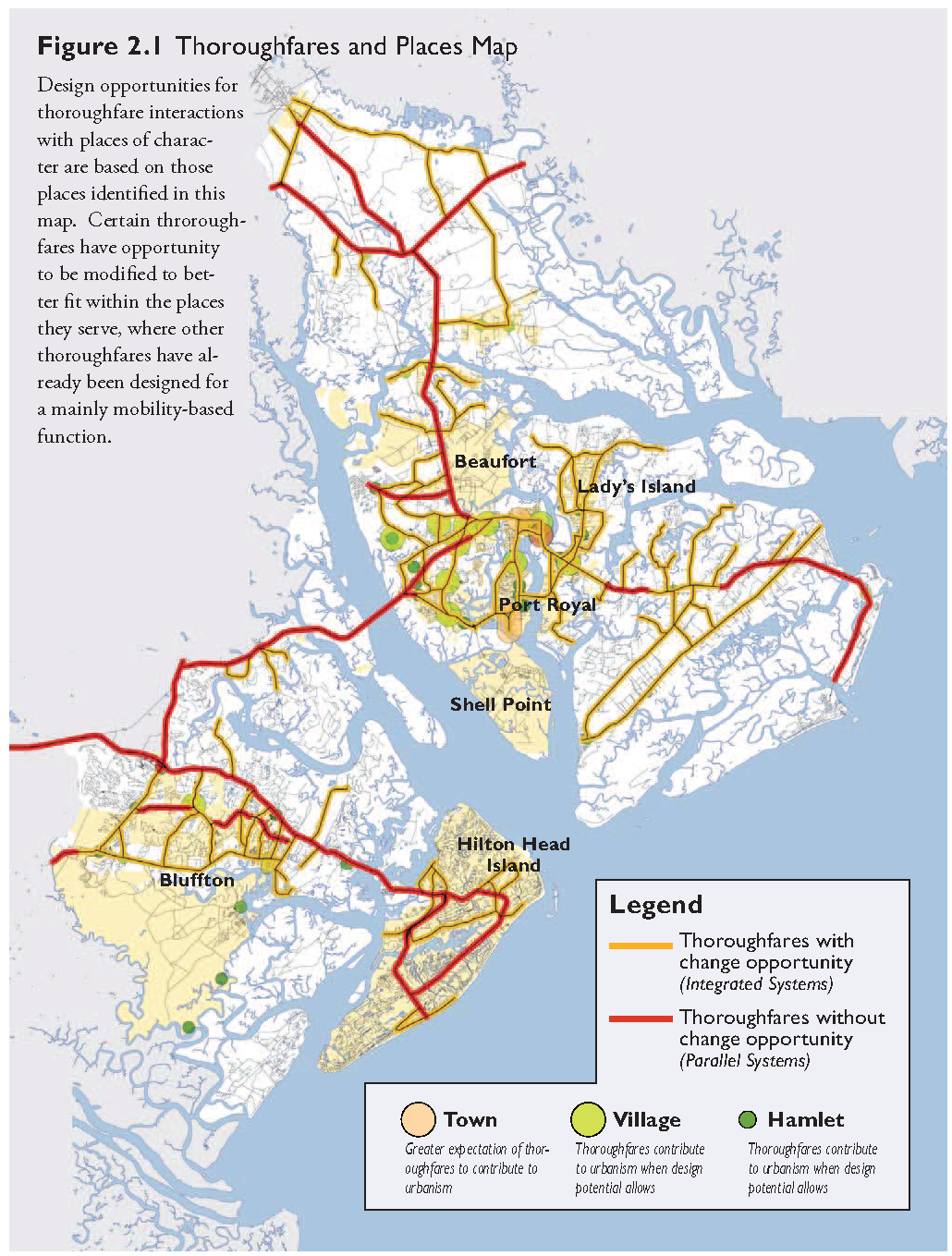
Thoroughfares and Places: The network of thoroughfare roadways in Beaufort County is the core of the County's transportation system. It connects the different places of character throughout the County, but equally importantly, it provides critical mobility over the County's many water features and wetlands.
The approach that the Form-Based Code takes in determining thoroughfare design relative to the Place types in the County is that thoroughfares and urban form should be compatible. Some thoroughfare designs have focused on mobility as their priority and do not provide a foundation for a walkable place. Other thoroughfares, while not necessarily designed to promote walkability, still exist within a relatively adaptable envelope and as they are expanded present opportunities for thoughtful design that pays attention to context.
With this in mind, the Technical Manual approaches thoroughfare and street design according to two basic principles:
1.
It is the basic responsibility of the County's thoroughfare network to provide mobility between the places of the County. This involves appropriate roadway design characteristics to provide for the needs of passenger and freight vehicles and to maintain reasonable speeds for connecting long distances within acceptable travel times.
2.
Within place districts as illustrated in the Form-Based Code's Places Map, the thoroughfare system needs to respond to land use contexts and take on roadway design characteristics that suit a walkable, pedestrian-oriented built environment. In some cases this means roadway design that allows buildings to respond directly to the street; in other cases this means making adequate provision for a system of parallel and connecting streets to separate land use access demands from a principal roadway's primary mobility function.
Certain places of character as identified in the Form-Based Code's Places Map are served by arterial roadways already designed for higher-speed mobility purposes. These roadways represent significant public investment in providing mobility options for the County, but they do not need to preclude walkable, compact development in Code-designated places of character. The focus on these roadway sections is to identify opportunities for local street network and pedestrian crossings that provide local land use access but that do not call for alterations to thoroughfare roadway design.
Other places of character are served by thoroughfares that still retail a lower-speed design. In these, the future de- sign of thoroughfare roadways and intersections should better respond to the needs of the place they are serving. Chapter 2 focuses on detailed plan-view diagrams that explain these treatments and that provide planning-level project design criteria for future capital improvement projects.
1.3.4
Network Capacity and Support: Another fundamental element in a sustainable street system is connectivity. Connected streets allow a greater number of alternative routes and do not force the main arterial system to bear the burden of all vehicle trips. Early identification of opportunities for connectivity and redundancy should be taken to create capacity without a degradation of walkability. Principles of connectivity should also be stressed in private development. Allowing private sector development to disconnect from the street grid causes disproportionate impacts on the arterial streets and costs that will have to be borne by the full taxpaying public.
The design of roadway network has a direct bearing on the design of the roadways themselves. Urban street networks featuring short block lengths and multiple connectivity options are able to concentrate system capacity in a small area without needing for individual roads to be large and relatively unsuitable for pedestrian, bicycle and transit movement. Suburban and rural networks, on the other hand, feature a lesser intensity of streets; major concentrations of land development on individual streets in these types of networks often requires the streets to be wider and have more capacity to accommodate that development's traffic.
It is true that intersections are the points where roadway capacity throughout a transportation system is tested, but at the same time not all traffic at the intersection of major roadways needs to be processed through the primary intersection itself. Supporting local network can assist major thoroughfares in the distribution of traffic, especially local traffic making a series of short trips. This allows major street intersections to be prioritized for major regional movements and frees them from the added burden of purely local trips. The end result of the place's street network design may be that new intersections (allowing full ranges of movements from the secondary cross streets) are introduced to the thoroughfare system in places of character. However, even with added intersections and signals, the overall operations of the principal thoroughfare intersection are facilitated by "sorting" many of the local movements onto parallel supporting street network.
1.4 - Fiscal Sustainability
Even in times of abundance or surplus, it is wise to plan for a future that might be more constrained. Transportation agencies across the country are finding that such a constrained future is a virtual certainty based solely on the maintenance cost of infrastructure as areas mature and age. Most transportation agencies reach a break point past which the cost of maintaining in-place facilities rises at a faster rate than new revenues.
1.4.1
Right-of-Way Costs: One of the largest expenditures in most capital projects is right of way. As areas urbanize, these cost make up a growing percentage of project budgets. Naturally, it makes good fiscal sense to find safe and effective ways to minimize these costs. One easy place to find relief is to look at the width of street corridors - both in terms of the number of lanes and the width of lanes.
1.4.2
Capital Costs: While rethinking street widths clearly has impacts in terms of right of way costs, construction costs can likewise be reduced. A five-lane street that employs ten-foot lanes rather than twelve-foot lanes will realize a 20% reduction in paving costs. If one assumes an average cost of paving a road of $15.00 per square yard, shaving even a mere four feet from existing street widths can yield cost savings of more than $35,000.00 per mile of construction.
In addition, since narrower streets produce less impervious cover and runoff, additional savings can be realized in the reduced size and cost of downstream stormwater management facilities. Since impervious surfaces will be reduced, a similar cost in drainage infrastructure can be expected. The use of narrower streets will also reduce the amount of impervious cover created by new development and, consequently, reduce the stormwater runoff and associated pollutant loads. Streets constitute the largest share of impervious cover in residential developments (about 40 to 50%) particularly. Creating narrower streets can result in a 5 to 20% overall reduction in impervious area for a typical residential subdivision. Since nearly all the pollutants deposited on street surfaces or trapped along curbs are delivered to the storm drain system during storm events, this reduced imperviousness translates directly into less stormwater runoff and pollutant loadings from the development. From the standpoint of stormwater quality, residential streets rank as a major source area for many stormwater pollutants, including sediment, bacteria, nutrients, hydrocarbons and metals (Steuer et al, 1997, and Bannerman, 1994).
1.4.3
Revenue: Finding areas to reduce costs is only one benefit of these sustainable approaches. Addressing Beaufort County's revenue sources is also prudent. While public agencies are not often thought of like corporations, they have some things in common. Like any financial entity, the quality of today's investment can have significant impact on tomorrow's revenues.
At the end of the day, a road project is really a land development project. Just as a real estate developer has to develop his land in a way that creates an economic return consistent with the cost of the land, Beaufort County will have different opportunities with the different rights-of-way that they own. Part of the County's revenue is generated on the basis of property values. Creating projects that add value to the community will translate to greater property value for owners. That greater value will be returned to Beaufort County in the form of tax revenues.
For example, the construction of a wide, high-speed arterial street with narrow, attached sidewalks can really only support one type of private investment. The high speeds do not allow the close intersection spacing needed to make an urban center-type network function. The high speeds coupled with the narrow, unbuffered sidewalks do not allow the creation of a viable pedestrian environment of the moving of buildings closer to the street. The only logical market response to this type of street is single story strip commercial fronted by parking. While this is a perfectly valid and economically viable form of development, it has certain inherent drawbacks. Since it is single story, the ability to collect revenue is limited by the available acreage. Construction methods for this type of development are geared toward buildings with a 5- to 15-year lifespan, over the course of which diminishing returns can be expected. This lifespan also dictates that at some point the buildings must be replaced entirely.
On the other hand, creation of a connected network of walkable streets might support a more diverse and more valuable mix of uses, such as ground floor retail with residential above. This higher use will generate higher tax revenue which will result in more money returned to Beaufort County coffers for improvements and maintenance of the system.
Section 2 - Thoroughfare Treatments in Places of Character
As discussed in Chapter 1, Beaufort County's arterial thoroughfare network is the spine of its transportation system. The many natural barriers presented by water and wetlands complicate simple, direct access between centers of population in the County. Partly for this reason, residents perceive travel between places in the County to be long and time-consuming. With this in mind, it is critical that the thoroughfare network continue to provide timely connections between different places of the County. However, this does not need to mean that the individual components of the thoroughfare network need to take a uniform design profile, especially in places of special character where the Form-Based Code is intended to apply most prominently.
This section introduces a series of design recommendations for Beaufort County thoroughfares. It is based on the Form-Based Code's Places Map and identifies key design challenges for the specific thoroughfare roadways that serve them. It assumes a county-wide system of thoroughfares (detailed on the following page) and identifies specific treatments for thoroughfares in places of character. It is important to note that these are conceptual guidelines intended to reinforce the principles of the Form-Based Code in places of character, and these are not intended to be recommendations for specific capital projects. As such, they have not been tested or analyzed based on any particular development program but instead represent a desired outcome to support the character and multimodal transportation potential of development allowed under the Form-Based Code.
Section 3: - Collector and Local Street Design
As discussed in Section 2, Beaufort County's arterial thoroughfare network is the spine of its transportation system. The many natural barriers presented by water and wetlands complicate simple, direct access between centers of population in the County. Partly for this reason, residents perceive travel between places to take considerable amounts of time; in response, the thoroughfare network has been preserved as the primary means of cross-county mobility.
This section addresses specific design components to be used throughout the County. Section 3.1 describes street designers who wish to assemble a different cross-section from those detailed in the previous sections. The intent of this flexibility is to allow a broader range of street designs, although customized designs are not allowed as of right and are subject to comment and revision through the relevant jurisdiction's development review process.
2.1 - Thoroughfare Design Opportunities
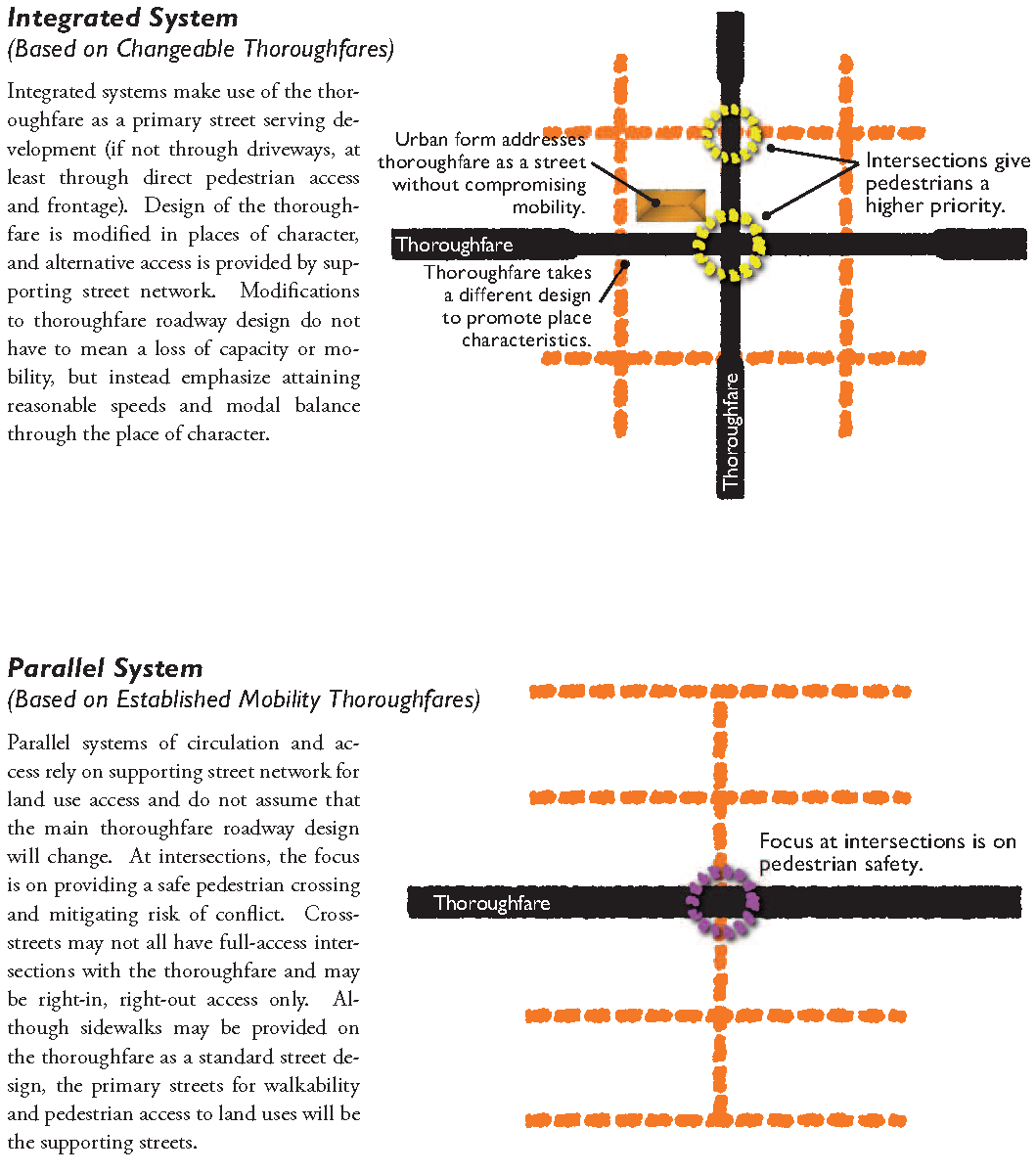
Figure 2.1 on the following page identifies a basic thoroughfare roadway system and depicts it in two basic classes: Roadways that have an opportunity for change through different designs, especially where the roads serve places of character (referred to as Integrated Systems), and roads that have been constructed with regional mobility as their first priority and have design recommendations that focus on separation of local movements through parallel street network (Parallel Systems). Integrated Systems thoroughfares are explored in terms of potential modifications to roadway cross-section, if not in terms of capacity, in terms of lane width, streetscape and roadside elements. Parallel Systems, on the other hand, are not recommended for change. Opportunities to promote walkability come from off-system street network.
In terms of Integrated Systems, the following are considered in each of the specific design recommendations:
•
Roadway Design Transitions. This deals with how an existing highway design transitions into a more livable, community-oriented design. Design elements that allow this transition to hap- pen include lane widths, introduction of raised planted medians, and placement of street trees and streetscape planting.
•
Place-specific details. Within places of character, either the primary roadway cross-section should respond to the place's land use context or highway designs should accommodate supporting street and pedestrian network to serve development.
As discussed previously, some of these thoroughfares have already been designed to prioritize mobility and as such take on the character of high-speed, limited-access roadways. Instead of proposing costly projects to change the primary roadway in these Parallel Systems, the Technical Manual explores opportunities for connecting street network that better serves local land uses and separates local trips from mobility-oriented arterials.
Figure 2.1: Thoroughfares and Places Map
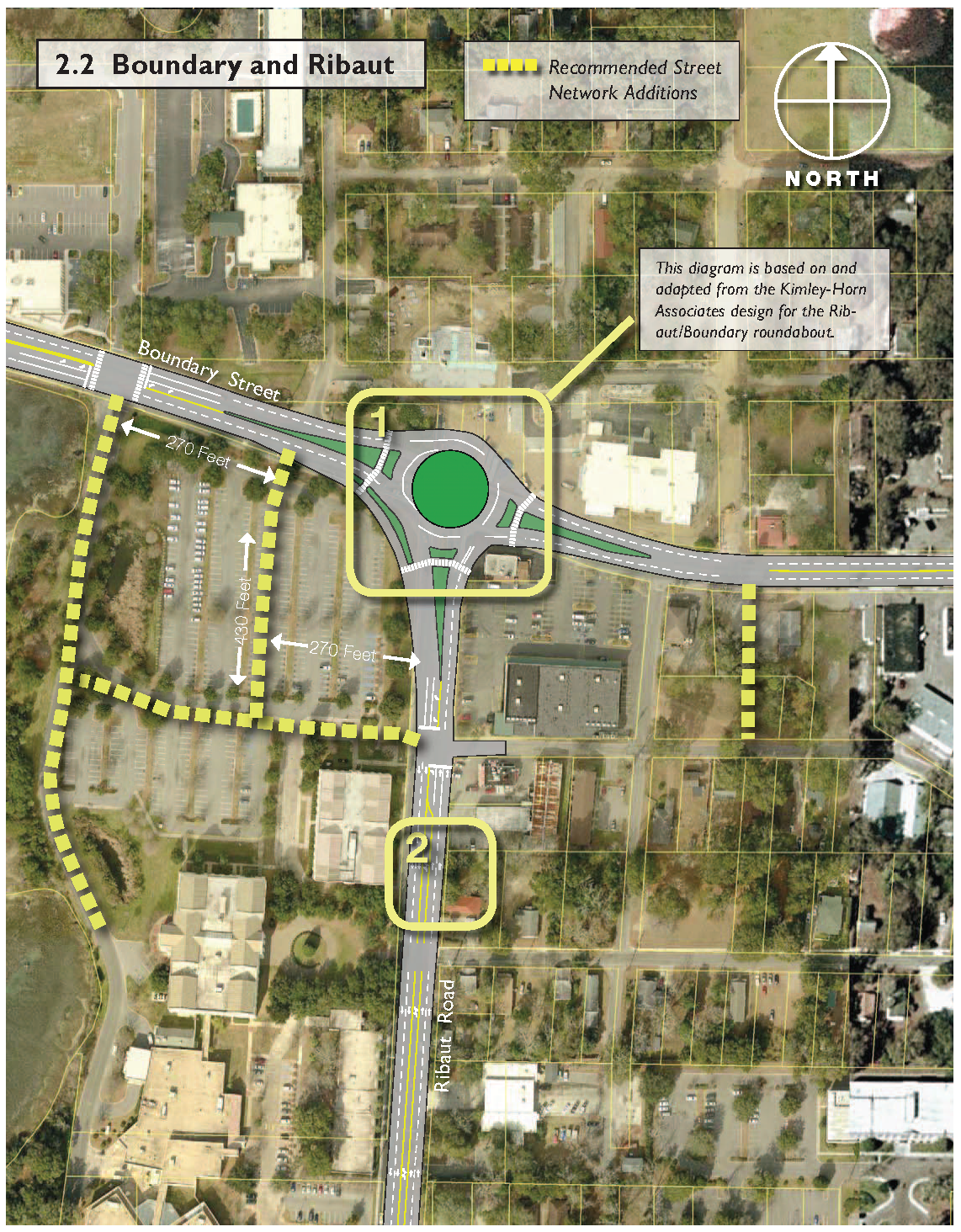
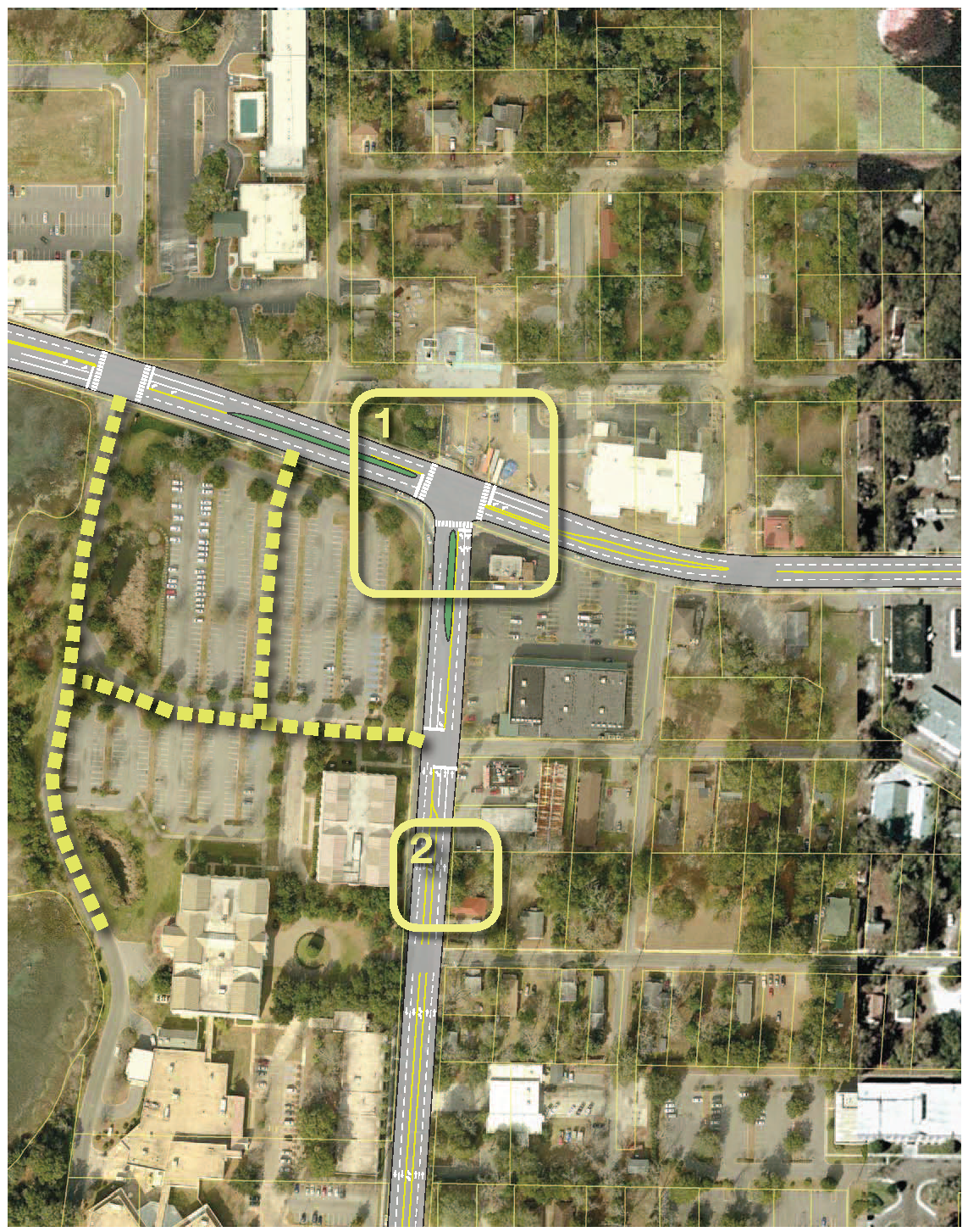
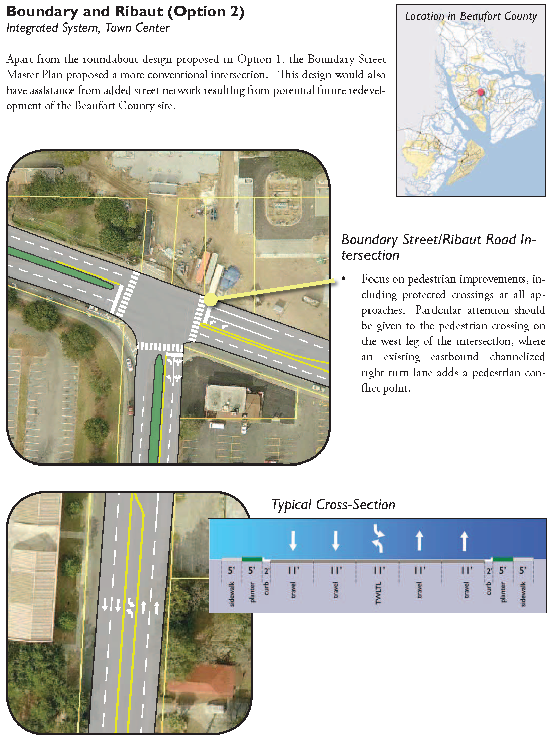
2.2 - Boundary and Ribaut
Figure 2.2: Boundary and Ribaut
Boundary and Ribaut (Option 1)
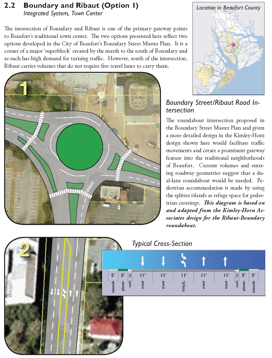
Boundary and Ribaut (Option 2)
2.3 - Boundary and Robert Smalls
Figure 2.3: Boundary and Robert Smalls
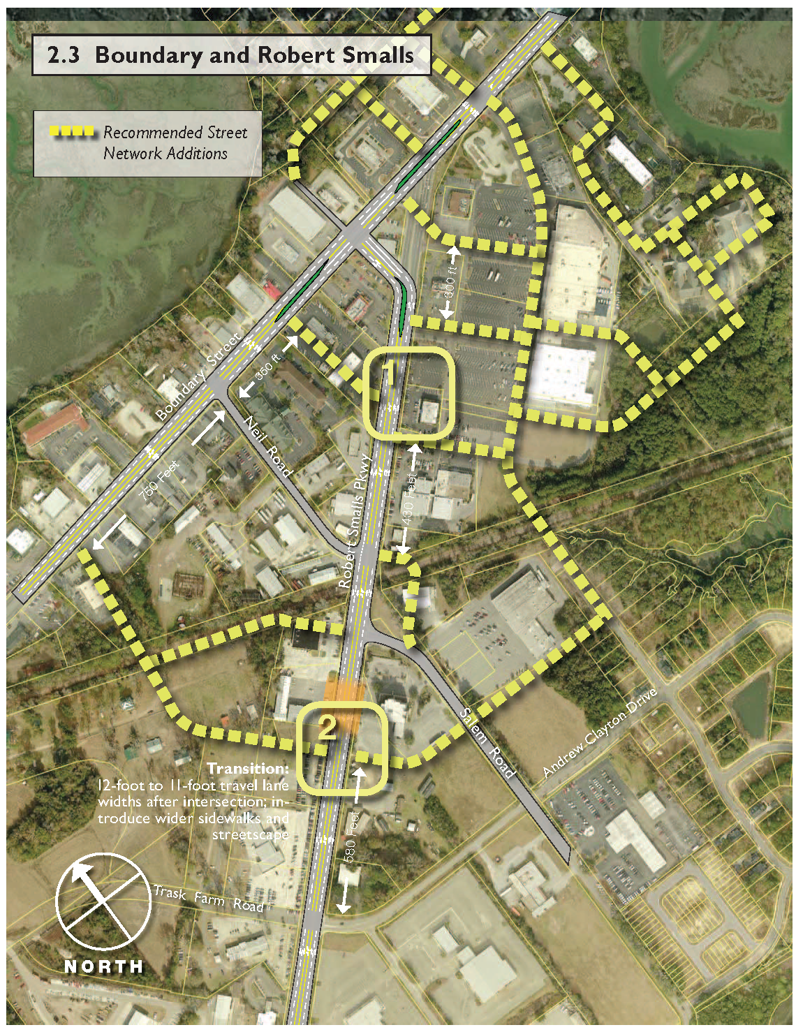
Boundary and Robert Smalls
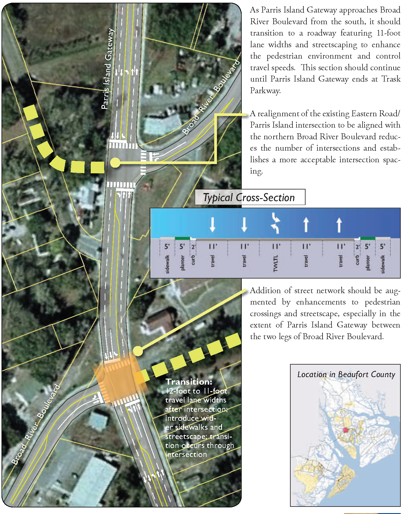
2.4 - Burton Village
Figure 2.4: Burton Village
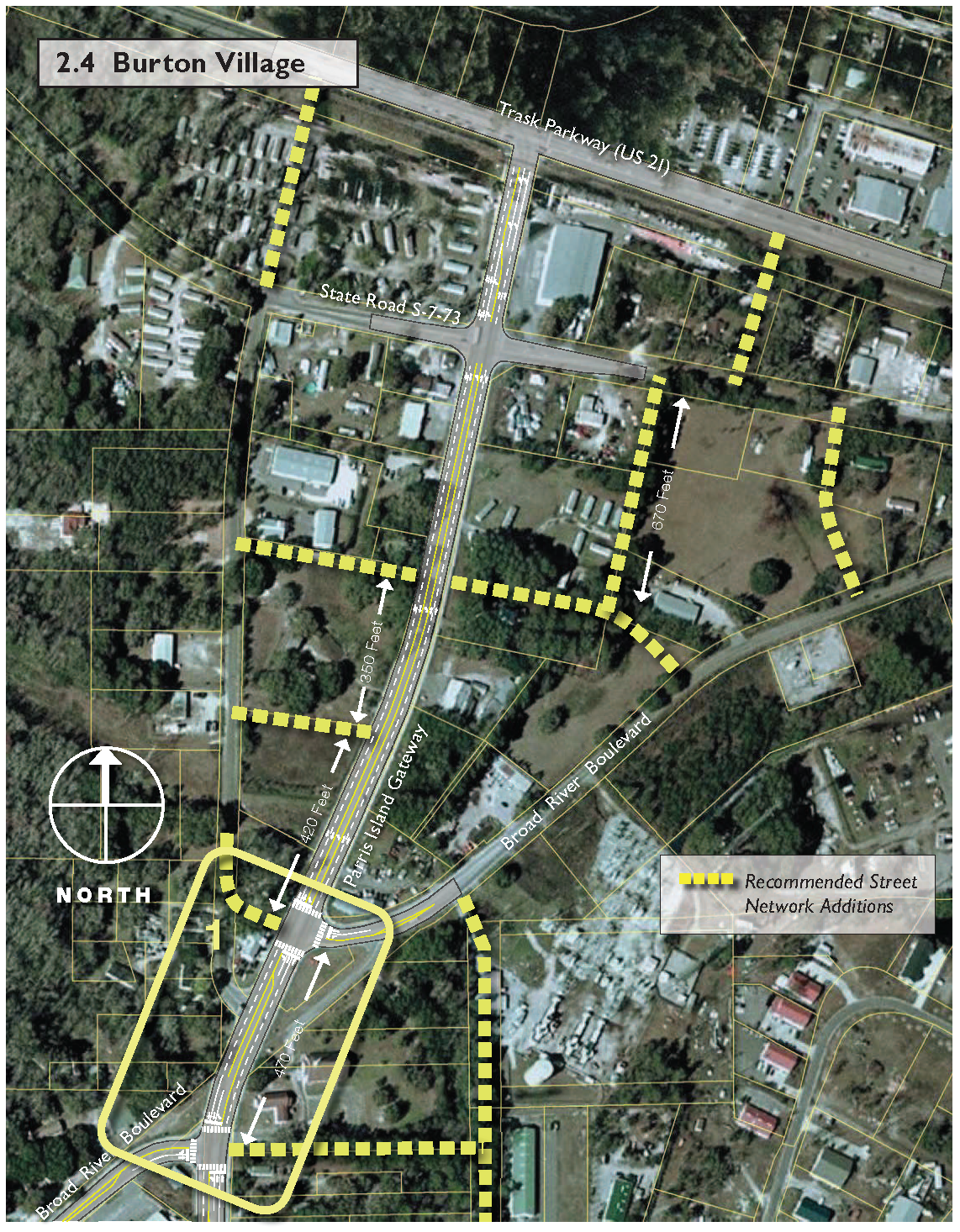
Burton Village
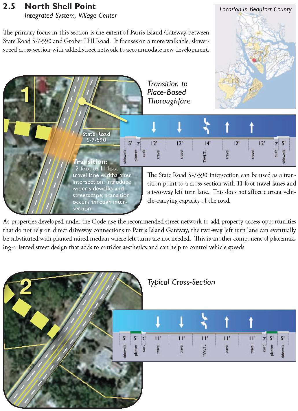
2.5 - North Shell Point
Figure 2.5: North Shell Point
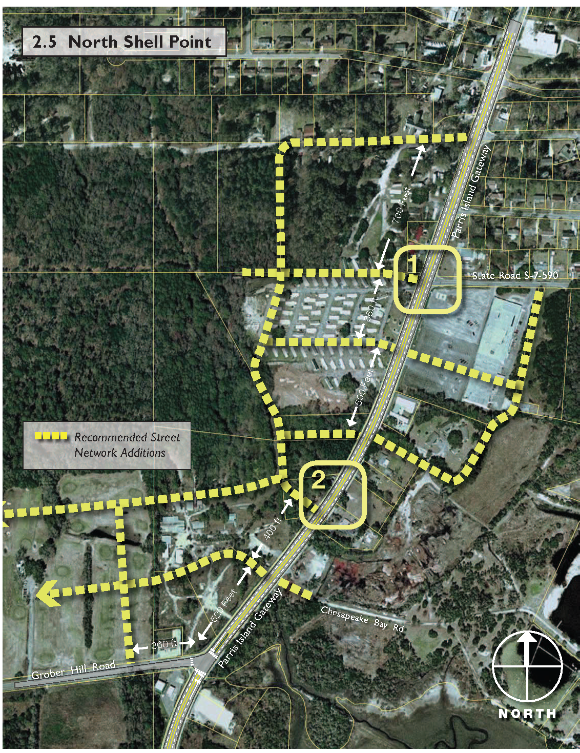
North Shell Point
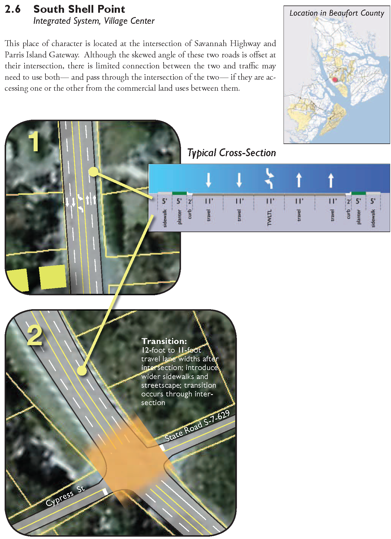
2.6 - South Shell Point
Figure 2.6: South Shell Point
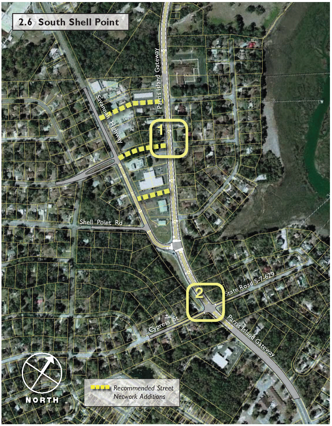
South Shell Point
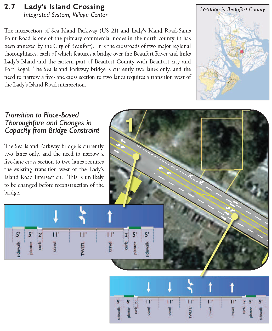
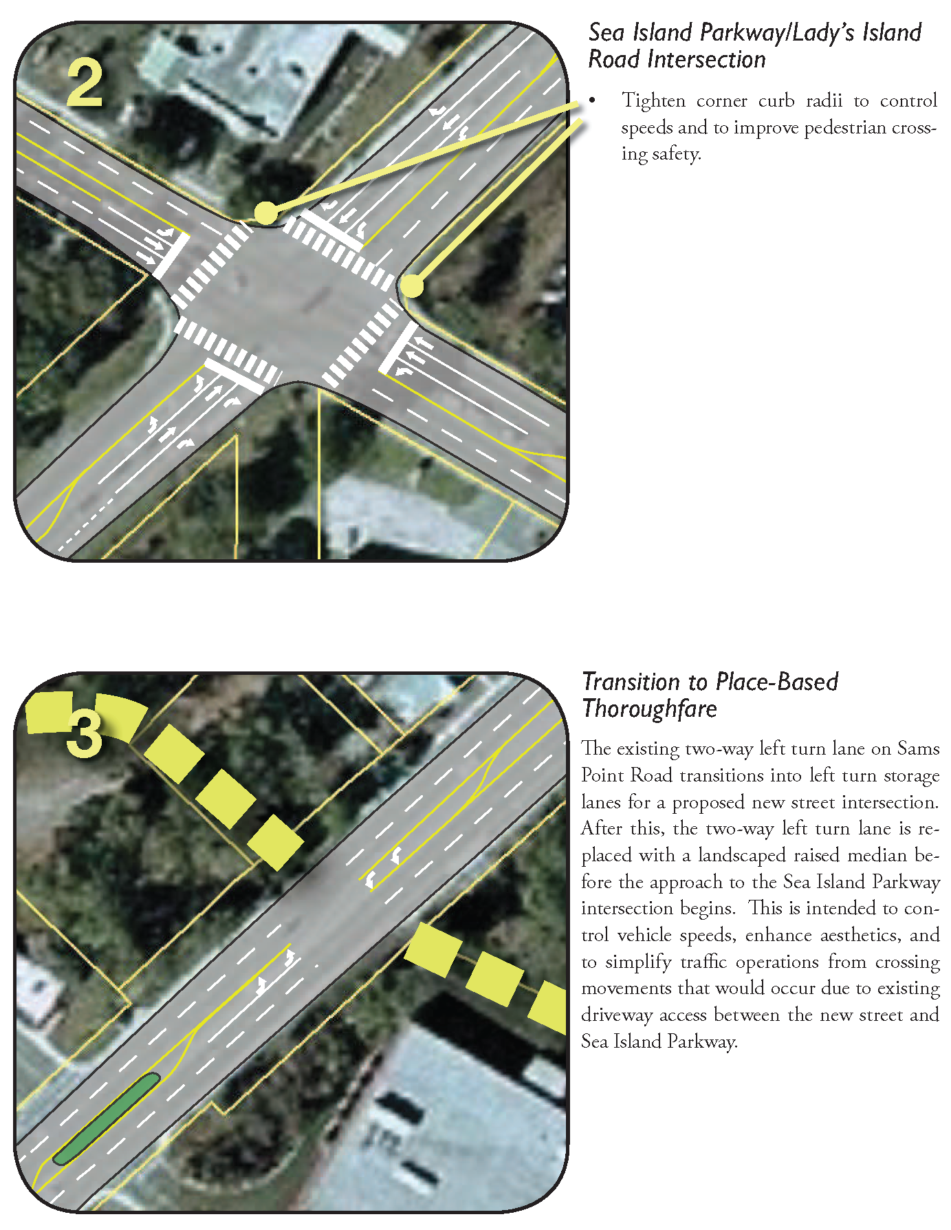
2.7 - Lady's Island Crossing
Figure 2.7: Lady's Island Crossing
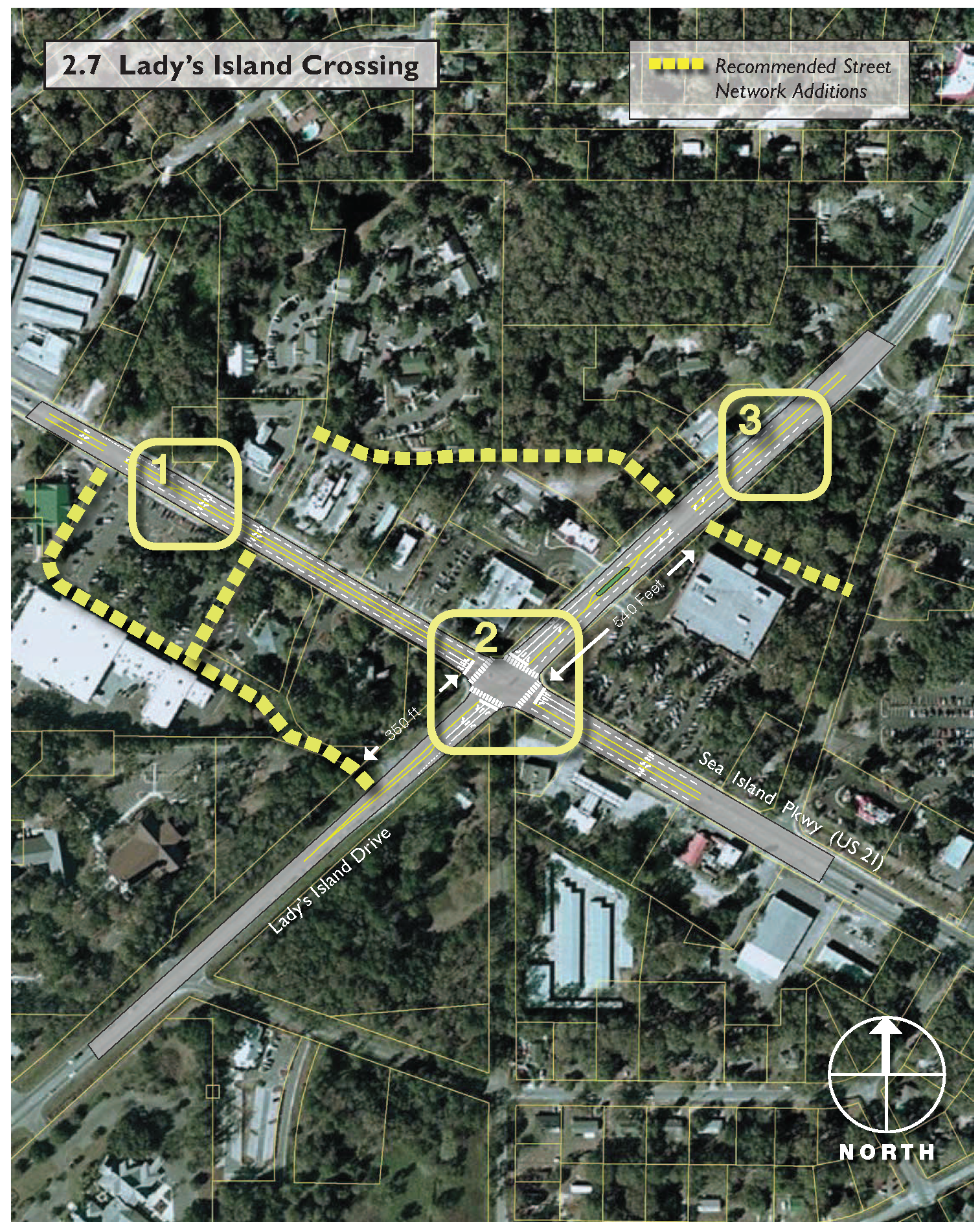
Lady's Island Crossing
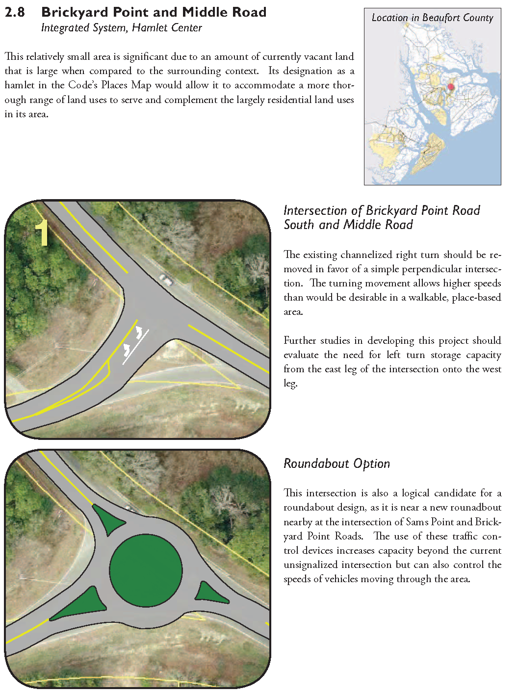
2.8 - Brickyard Point and Middle Road
Figure 2.8: Brickyard Point and Middle Road
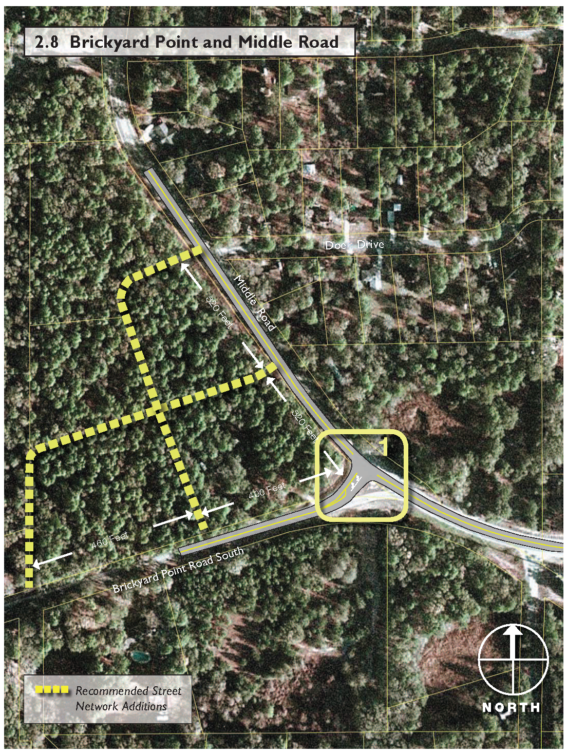
Brickyard Point and Middle Road
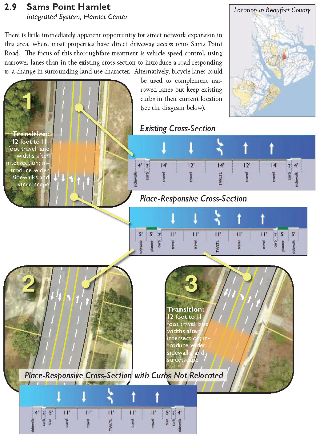
2.9 - Sams Point Hamlet
Figure 2.9: Sams Point Hamlet
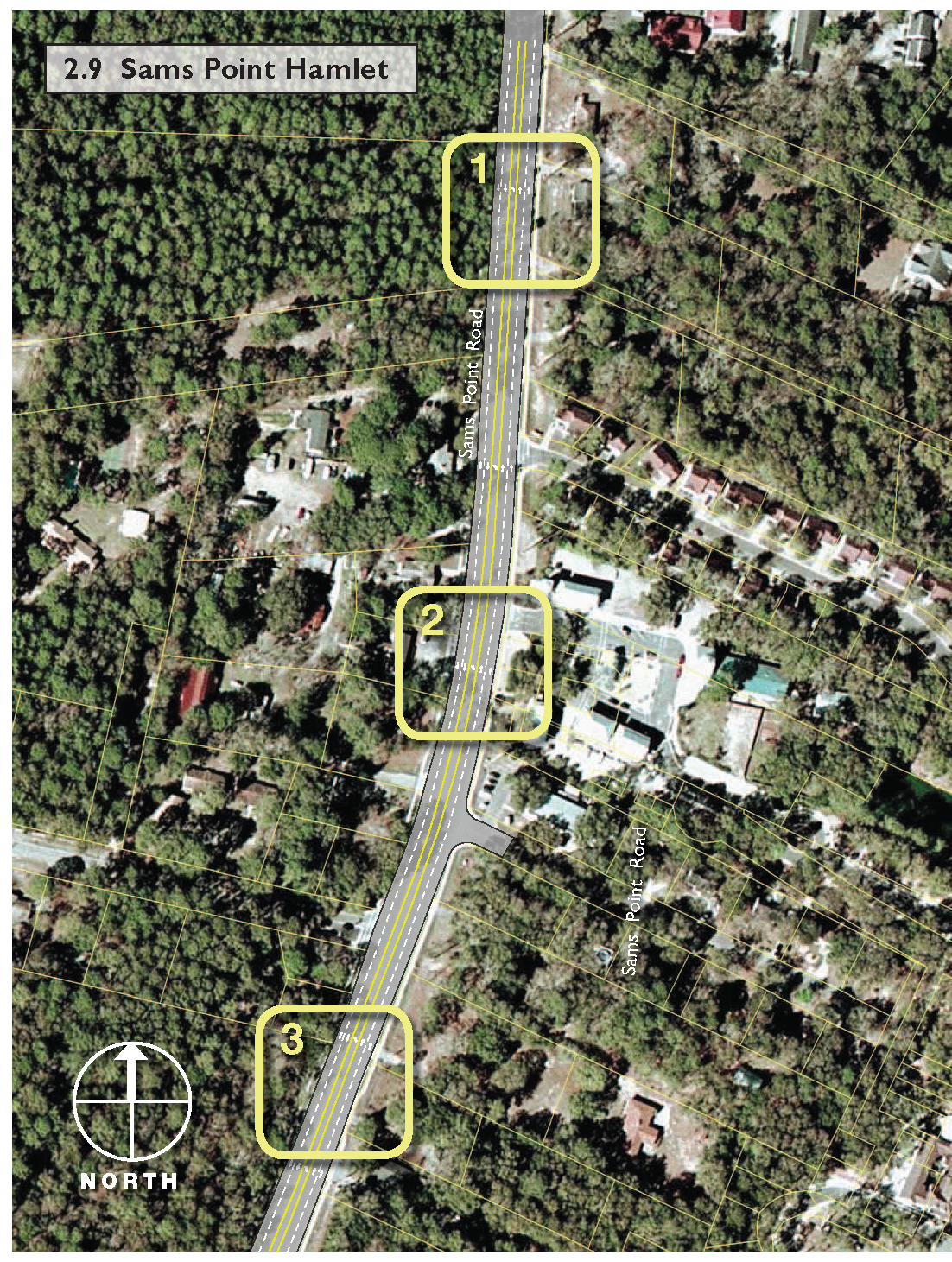
Sams Point Hamlet
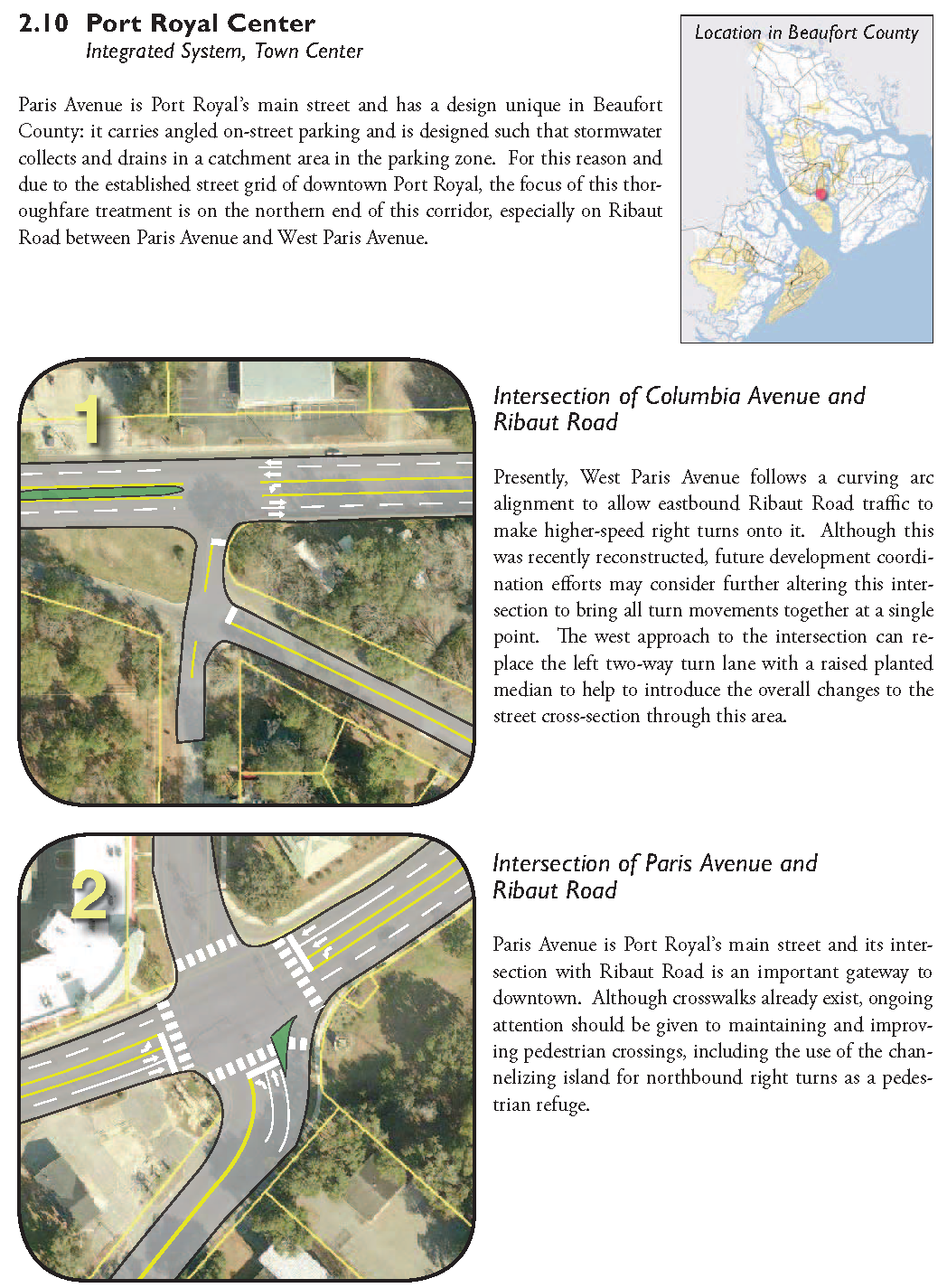
2.10 - Port Royal Center
Figure 2.10: Port Royal Center
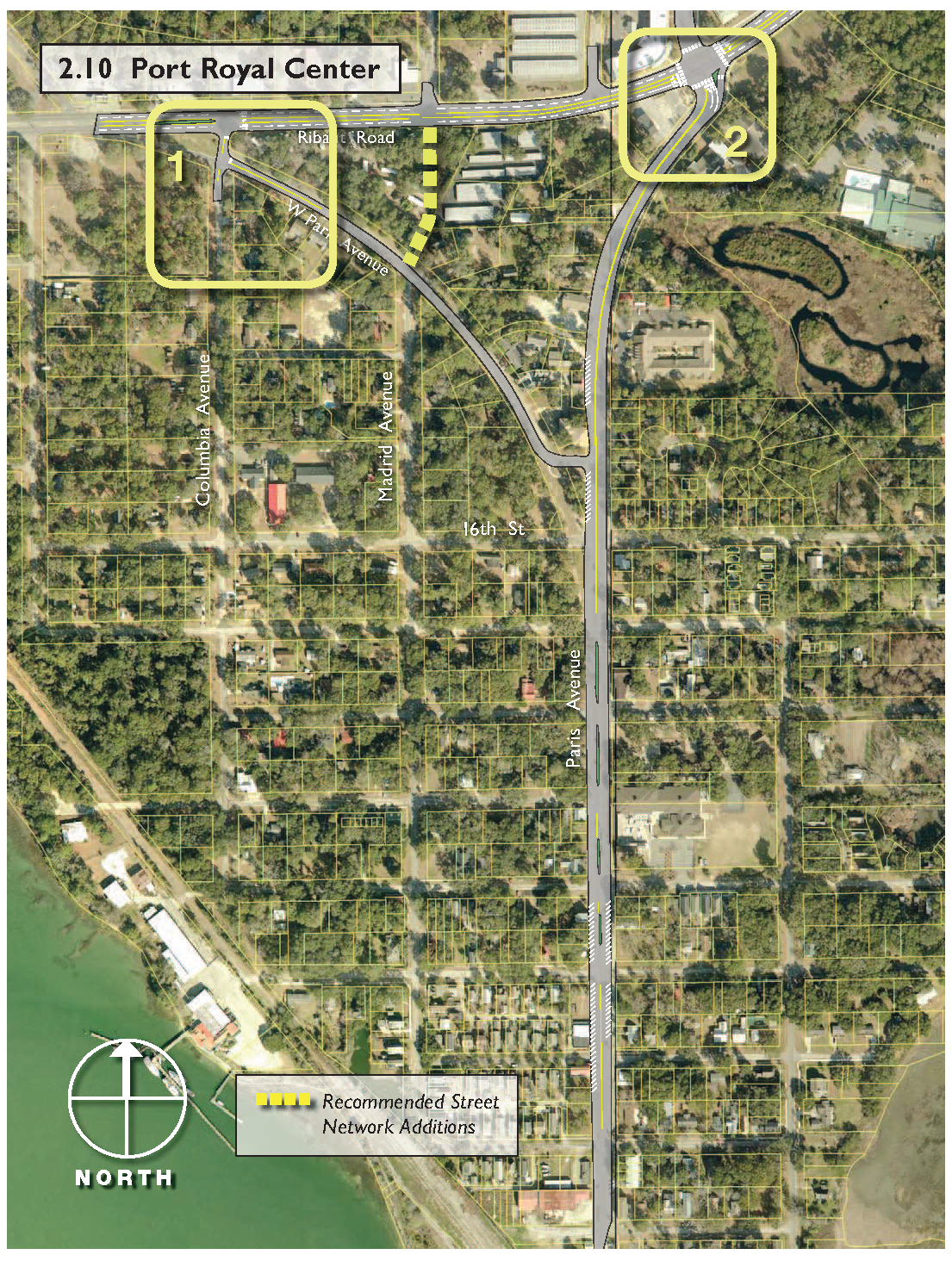
Port Royal Center
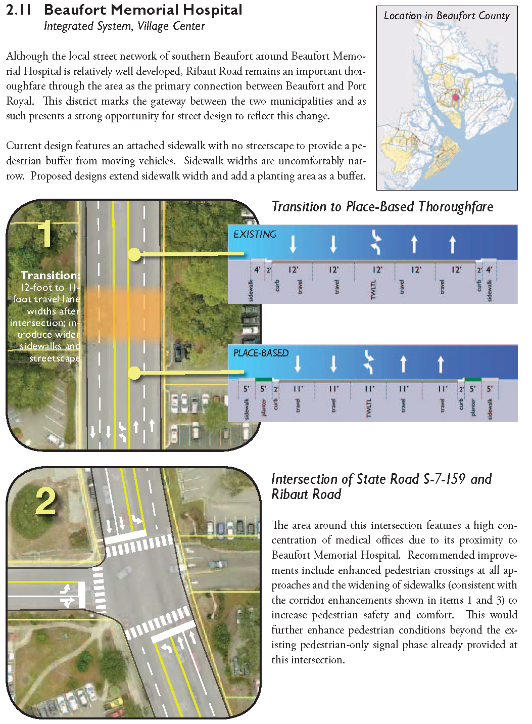
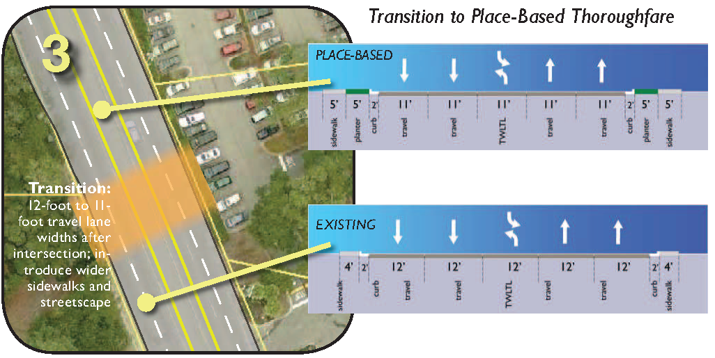
2.11 - Beaufort Memorial Hospital
Figure 2.11: Beaufort Memorial Hospital
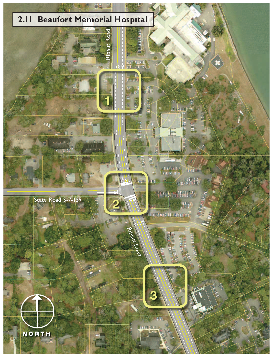
Beaufort Memorial Hospital
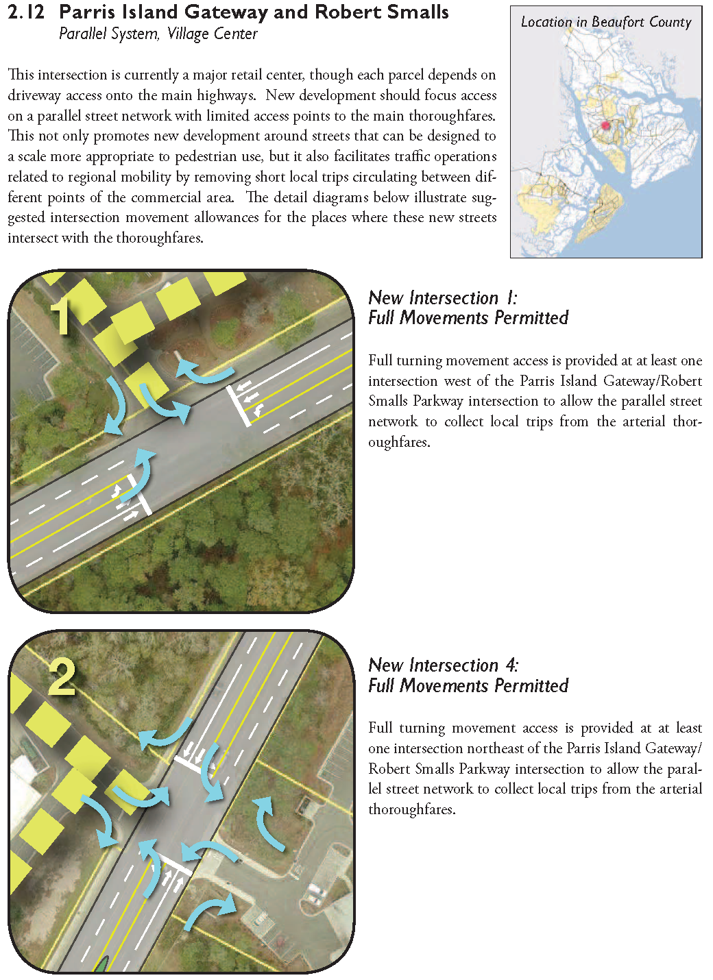
2.12 - Parris Island Gateway and Robert Smalls
Figure 2.12: Parris Island Gateway and Robert Smalls
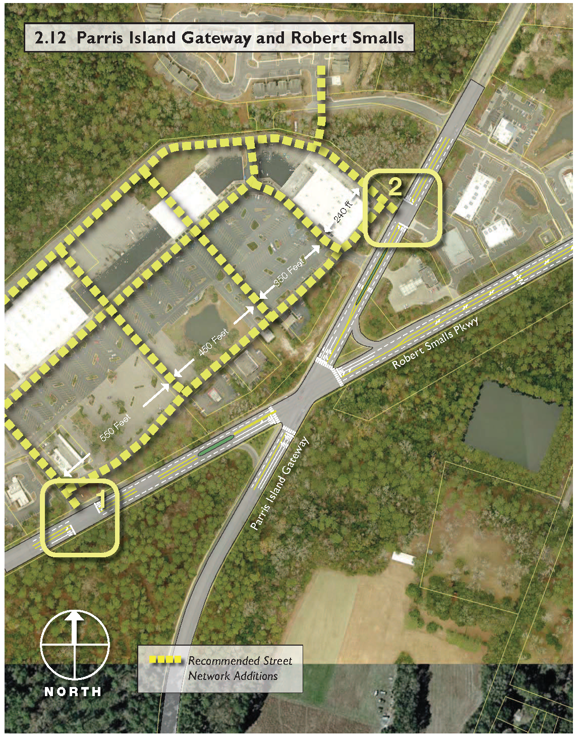
Parris Island Gateway and Robert Smalls
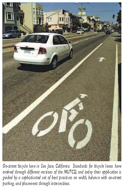
2.13 - Corners Community
Figure 2.13: Corners Community
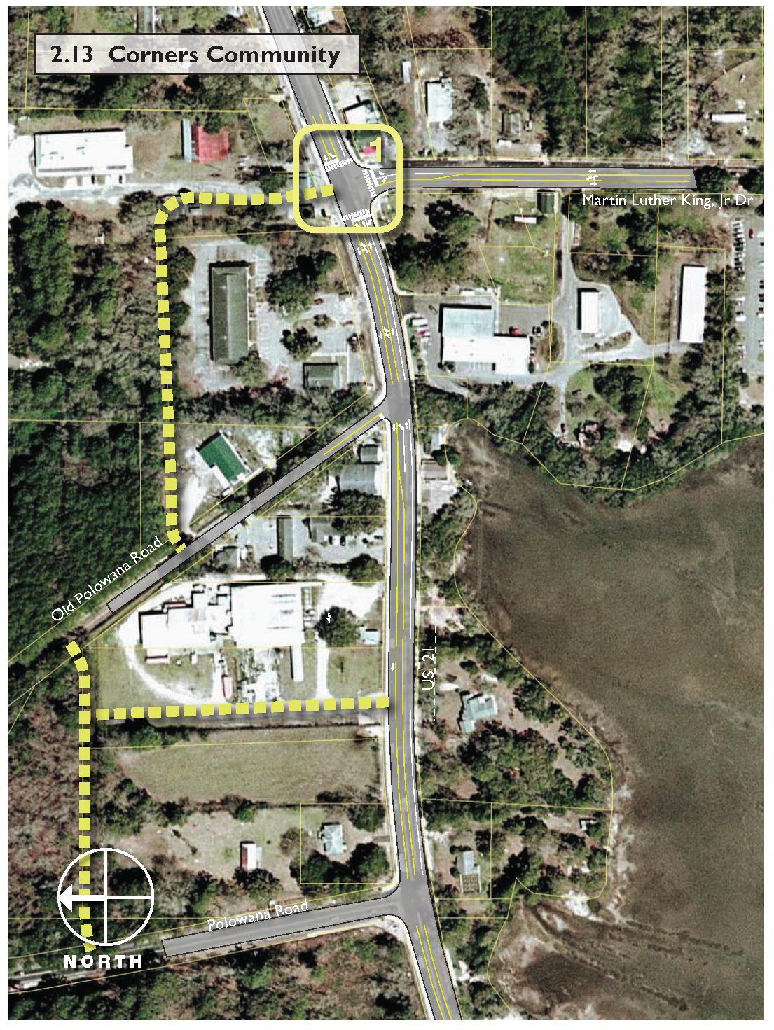
Corners Community
3.1 - Street Network Design
Although the profile and specific design of a street are critical components to its function, the overall street system is the foundation of land development and its design is similarly important in how well it will accommodate place-making. As an intent of the Form-Based Code is to facilitate walkable, desirable places, the configuration of net- work deserves particular attention.
From a policy perspective, street networks featuring appropriately scaled grids of local and collector streets are a vital element to design guidelines and subdivision regulations that seek to create a livable community. Traditional development patterns sought to utilize valuable land as efficiently as possible by building to the street and utilizing rear alley-based access, most notably through mid-block alleys, to provide service to buildings. This way of building had the well-known advantages of allowing more immediate walking access to the building and keeping services off of already busy streets. This pattern changed to favor automobile access in the 20th century. In recent years planners have sought to move back to this kind of development and are increasingly developing policies and land development regulations requiring it. However, the placement of buildings alone does not guarantee the successful function of a traditional urban environment: The means of circulation defined by the streets must promote adjacency and accessibility so that the transfer of goods and information is possible. When the connections that intersecting streets provide are too large, the compact nature of the urban environment is lost and it is more difficult to use land efficiently.
In most cases, a building and form typology that is adaptable and sustains multiple uses under its roof can fit into a smaller block, but local concerns over parking availability may call for a slightly larger block size (even in cases where the Code calls for building to the street, parking needs may necessitate a larger block because they require at least some of a building's parking to be on site, behind the building).
3.1.1
Block Size: Small blocks are advantageous because they allow the development of a finer grain of built fabric that at once improves the efficiency of the transportation system, promotes a more healthy, versatile economic base and enhances the nature of the built environment. As the legacy of post-World War II development patterns has given rise to a paradigm of larger sites and greater space between public thoroughfares, it is essential to consider the benefits that defining block size has for a place's character and wellbeing.
With smaller blocks it is feasible to set smaller areas for different uses as a dense street network provides adequate circulation between origins and destinations, where with larger blocks it is difficult to expect effective circulation between uses without the addition of a de facto internal street system. This is often a problem with large commercial sites, such as shopping malls and newer "power centers." The size of the sites and the parking required to serve the commercial space necessitates an internal circulation system, yet the residential areas that provide the shopping center's market are entirely separated from it.
Generally speaking, block spacing should allow cross-street access in places of character no less than every 300 feet but no more than every 700 feet. Total block perimeter, or the sum of all block face lengths, will not exceed 2,000 feet. This intended flexibility is based on a variety of factors. First, existing property lines may facilitate street placement at irregular intervals as properties redevelop. Second, the intended land use for a particular area is likely to have bearing on the need for street network layout: residential blocks tend to take a different form than commercial blocks and as such may require greater length in one dimension.
This should not suggest that there are limits to what works: A 250-foot block size is not necessarily too small, but when coupled with large lot sizes and wide street rights-of-way it limits the potential for the blocks to redevelop. The flexibility in block face lengths suggests the difficulty in assigning a "breaking point" value to what is too small or too large. The following cases illustrate different approaches to defining dimensions:
•
McKinney, Texas expresses its standards numerically: The maximum block length permitted is 600 feet, supported with statements that call for provision of multiple access ways between destinations.
•
Hercules, California limits its block faces to be no longer than 500 feet.
•
Miami-Dade County, Florida limits block perimeters in its Traditional Neighborhood Development zoning district to 1,300 feet or less with no block face greater than 400 feet.
It is also important to remember constraining factors and to respect them with block sizes that allow contiguous spaces when needed. Aside from the obvious examples of parks, schools, and other land uses which demand more land than a typical small block may allow, block patterns must account for environmentally sensitive land or other areas needing special protection. A network of small blocks does not require that the same sizes be used over sensitive lands; wetlands, stream buffers, and other environmentally sensitive lands are protected from interruption by more frequent streets.
3.1.2
Access Management on Arterial Roadways: The purpose of Section 2 of this manual, the guidance on specific thoroughfare design treatments, is to recommend design measures responsive to particular environmental conditions and in so doing allow regional mobility roadways to respond appropriately to places of character. However, as development under the Code continues apart from these specific recommendations, appropriate access should be provided on thoroughfare roadways to ensure that a balance between regional roadway function and land development needs is met.
Conventional access management regulations for state and County roadways require the granting of an access waiver when access is sought at spacings less than a set of standards established by SCDOT. Instead of tying development of the Neighborhood Plan areas to ongoing cycles of access waivers, the County should work with SCDOT to establish a different set of access management standards for Traditional Neighborhood Community Plans outside of the requirements of SCDOT's Access and Roadside Management Standards (ARMS), defined as follows:
•
Major Arterial Road (divided four-lane): 800 feet for full-access, 500 feet for partial access.
•
Arterial Road (two-lane): 500 feet for full access, 400 feet for partial access.
•
Collector road and all others: 400 feet for any access.
•
In any event where offset "T" intersections are closer together than these minimum requirements, the intersection will be allowed only right-in, right-out access onto the main thoroughfare. The Thoroughfare Treatments in the Technical Manual have sought to avoid this condition as much as practical and emphasize true four-way intersections that eliminate this offset.
•
Collector roadways are given full turning movement access at intersections with arterials.
•
Local roadways will be given right-in, right-out access to arterials when they are part of a parallel system (as those discussed in Section 2) and they are less than 800 feet from another full intersection.
•
Driveway access will be limited to one driveway per parcel on arterial and collector roadways. Exceptions may be granted by the agency responsible for permitting roadway access when the proposed use is an emergency response facility, such as a fire or police station. Driveway cross-access, as specified in the existing Beaufort County Zoning and Development Standards Ordinance (Section 106-2796(c)) should be sought when driveways on arterials would be located at intervals of less than 300 feet.
These recommended spacing requirements generally follow the guidance in ARMS Chapter 5, Section 5B-1 ("Un-signalized Intersection Spacing"), which state that "to operate efficiently, urban intersections should be a minimum of 500 feet apart." The Thoroughfare Treatments in the Beaufort County Technical Manual do not currently call for signalization of any particular intersections; as per standard guidance in the Highway Capacity Manual, this would be implemented when warranted by traffic or safety conditions.
3.1.3
Collector-Local Distribution: Based on FHWA guidance, collectors are typically two-lane roads that collect and distribute traffic to and from the arterial thoroughfare system, providing connections to and among residential neighborhoods and commercial and industrial areas. Local streets are focused more specifically on land use access and tend to be designed for slower speeds and lower traffic volumes. There is no formal rule for placement of each of the functional classes relative to one another: In other words, local streets can (and should) interface directly with arterial thoroughfares and do not need to rely on collectors to make the connection. In fact, reliance on collectors for interface with the arterial system tends to create a built environment with few and infrequently spaced intersections along arterials, a condition that is not conducive to the place-making objectives of the Code.
3.2 - Travel Lanes
3.2.1
Lane Width: Lane width has an influence on the safety and comfort of the driver. The width of the travel lanes selected should be influenced by the physical dimensions of cars and trucks, the desired speeds and the type of street under design. Studies have shown that drivers tend to be more comfortable traveling at higher speeds on roads with wider lanes. The allowable range of design lane width, per the A ASHTO guidance, is between 9 ft. (2.7 m) and 12 ft. (3.6 m). Wider lanes are typically associated with higher speed roadways such as freeways, arterials in suburban areas, and two-lane rural arterial and collector highways. As speed and volumes increase, additional lane width is often considered desirable to accommodate the variations in lateral placement of the vehicle within a lane. Greater lane widths also more easily accommodate wider vehicles in the traffic stream, such as trucks, buses, and recreational vehicles. Wider lane widths may also marginally increase the capacity of the roadway.
In urban areas and along rural routes that pass through urban settings, narrower lane widths may be appropriate. For such locations, space is limited and lower speeds may be desired. Narrower lane widths for urban streets lessen pedestrian crossing distances, enable the provision of on-street parking and transit stops, and may enable the development of left-turn lanes for safety. Lesser widths also encourage lower speeds, an outcome that may be desirable in urban areas. In considering the use of narrower lanes, however, designers should recognize that narrow travel lanes reduce vehicle separation from other vehicles and from bicyclists.
Recommended design values for lane width in rural areas in the A ASHTO Green Book are generally reflective of safety and operation benefits estimated from research published in NCHRP Report 362: Roadway Widths for Low Traffic Volume Roads (18). Lane width values communicated in the Green Book vary with design traffic volumes, the selected design speed, and the terrain (reflecting general construction cost effectiveness).
Green Book values for lower-speed urban street lane widths are less rigorously derived. There is less direct evidence of a safety benefit associated with incrementally wider lanes in urban areas, compared with other cross sectional elements. In fact, much of the more recently developed research suggests that in urban areas with a likelihood of pedestrian use, the lower speeds associated with narrower lanes actually improve safety. Here, provision for a total cross section that considers left-turning vehicles, medians, and the needs of pedestrians and bicyclists should be considered in selecting appropriate lane widths and cross section based on safety considerations. NCHRP Reports 282 and 330 demonstrate the operational and safety effectiveness of various combinations of cross section values for urban arterials.
3.2.2
Flexibility on Lane Width in the AASHTO Guidance: The AASHTO Green Book recognizes the need for flexibility and provides that flexibility, citing how lane width can be tailored, to a degree, to fit the particular environment in which the roadway functions (e.g., low-volume, rural roads or residential areas versus higher volume rural or urban facilities). For lower speed, lower volume rural roads and highways with little or no truck traffic, lane widths as low as 9 ft. (2.7 m) may be acceptable; lane widths substantially less than 12 ft. (3.6 m) are considered adequate for a wide range of volume, speed and other conditions. For the reconstruction of rural two-lane highways, the Green Book notes that less than 12 ft. or 3.6 m. lane widths may be retained "where alignment and safety record are satisfactory." In other words, widening a narrow existing highway is not mandated if its safety performance is acceptable. Flexibility is also evident for lower-class roads and streets, with recommended narrower lane widths consistent with lower design speeds on such roads.
The discussion of lane width in the AASHTO Green Book for urban areas also reflects a high degree of flexibility. It is noted that lane widths "may vary from 10 to 12 ft. (3.0 to 3.6 m) for arterials." Lane widths of 3.0 m [10 ft.] may be used in highly restricted areas having little or no truck traffic. Lane widths of 3.3 m [11 ft.] are used quite extensively for urban arterial street designs. For lower classification facilities, similar flexible language encourages the tailoring of an urban street cross section to site-specific conditions.
The Green Book consists of a mix of design guidance and policy statements (it has the word "policy" in its title, after all), which can sometimes cause confusion or disagreement. For example, the book states that "The 3.6 m [12 ft.] lane widths are most desirable and should be used, where practical, on higher speed, free-flowing, principal arterials. "The book does not make clear the basis for this policy statement (safety, convenience, preference, etc.). Nor does it define the term "practical." This could mean when physically possible or it could mean when few pedestrians are expected to be present. For many communities, the desire to create safe and walkable streets is seen as a sufficient practical consideration to bypass this policy recommendation of the Green Book in favor of narrower and allow- able, safe dimensions.
Under interrupted-flow operating conditions at low speeds (70 km/h [45 mph] or less), narrower lane widths are normally adequate and have some advantages. For example, reduced lane widths allow more lanes to be provided in areas with restricted right-of-way and allow shorter pedestrian crossing times because of reduced crossing distances. Arterials with reduced lane widths are also more economical to construct. If provision for bicyclists is to be made, see the AASHTO Guide for the Development of Bicycle Facilities. If substantial truck traffic is anticipated, additional lane width may be desirable. The widths needed for all lanes and intersection design controls should be evaluated collectively. For instance, a wider right-hand lane that provides for right turns without encroachment on adjacent lanes may be attained by providing a narrower left-turn lane. Local practice and experience regarding lane widths should be evaluated.
3.2.3
Lane Widths and South Carolina Highway Design Manual Requirements: Many of the thoroughfare treatments proposed in the Technical Manual strive to achieve pedestrian-friendly conditions conducive to the urbanism intended in Traditional Neighborhood Community Plans. One of the specific design measures these thoroughfare treatments propose is the narrowing of standard travel lane widths through certain Community Plan areas and potentially introducing curb-and-gutter sections to facilitate on-street parking and protect the pedestrian environment from stormwater runoff and flooding. These constitute street and highway design elements that are incompatible with South Carolina Highway Design Manual (SCHDM) requirements.
SCHDM provides guidance on context-sensitive design and maintaining consistency between design and driver expectations. Both of these are important components of the manual and suggest that a more compact form of development in which urban character and walkability are emphasized may call for a change in roadway design to accommodate them. For this reason, the Technical Manual has identified typical cross sections that differ from the existing cross-section but that are intended to help control motorist behavior to preserve a walkable environment and mitigate the risk of collisions at high-speed travel.
It is important to note that many SCHDM requirements appear oriented to roadway design outside of urbanized areas where space is available to allow wider cross-sections. In particular, most state roadway cross-sections specify a required width of 12 feet for travel lanes, 15 feet for center two-way left turn lanes, and from 12 to up to 28 feet for clear zone widths. In areas where Beaufort County has sought to concentrate development through land use policy and implementing codes, meeting these requirements is likely to be impracticable.
For these reasons, the guidance on context-sensitive design that SCDOT provides in the Design Manual should be interpreted as enabling a flexible understanding in defining the purpose and primary needs of a given roadway design. Section 9.11 of the SCHDM specifically mentions "10-foot wide lanes for a short distance where all other lanes are 12 feet" as an example of a service inconsistency in which driver expectations are not met by the road, suggesting a need for highway designers to strive for a uniform width regardless of surrounding land uses or building form. It cannot be ignored that built environment plays an important role in this expectation and that the roadway design should be consistent with these expectations. Drivers respond to a wide variety of environmental factors, not only elements of the cross-section. By tailoring the roadway's cross-section to be more appropriate to these environ- mental factors, a clearer "message" is delivered to motorists that speeds should be reduced and that other users of the roadway (namely pedestrians) are likely to be present.
3.3 - Bicycle Lanes
On-street bicycle lanes are not currently used widely in Beaufort County, and the Form-Based Code does not define a bicycle system plan for their implementation. However, bicycles are an important (and often under-utilized) link between walkability and connection over longer distances. Bicycling typically offers three to four times the speed of walking, thus resulting in significant time savings, and when places of character are closely spaced it can be a useful and legitimate mode of connection between them.
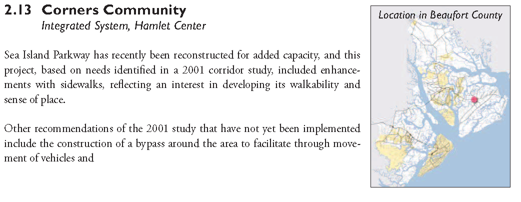
On-street bicycle lane in San Jose, California. Standards for bicycle lanes have evolved through different versions of the MUTCD, and today their application is guided by a sophisticated set of best practices on width, balance with on-street parking, and placement through intersections.
Striping bicycle lanes on roadways defines visible space for bicycle users separate from vehicle space. Bicycle lanes allow users of one mode to have more predictable movements with respect to users of the other mode. Bi- cyclists can be more confident that motorists will not drift into their travel space, and motorists are less likely to swerve outside of their lane to avoid bicycles traveling on the right side.
Striped bike lanes help novice and inexperienced bicyclists feel more comfortable bicycling, and therefore help to make cycling a legitimate and desirable mode of travel in urban areas. Continuity is important as well: the locations where bicycle lanes end can create dangerous situations of merging with auto traffic, so continuous striping of bicycle lanes is another important factor in perceived and actual safety to bicyclists.
Bike lanes should be a minimum of four feet in width, depending on the specific design of the roadway. A roadway with no curb, gutter, or on-street parking should be striped with at least a four-foot bike lane. Streets with parking should use a minimum of five-foot bike lanes, placed between the parking stalls and the vehicle travel lanes. Roads that allow parking without demarcated spaces should have a bicycle travel space of at least 11 feet if there is no curb or gutter. Curbs and gutters are considered right-side obstacles, so more space is desired if they are present: most often, an additional foot of bicycle space is used (AASHTO, 1999). Traditionally, bike lanes are placed between the parking lane and the travel lanes when parking is present; however, some more progressive designs place the bike lanes between the sidewalk and the parking lane, adding a barrier between cyclists and moving vehicles. These lanes, along with the traditional version of bike lanes, often have problems with motorists parking in the lane, so extra precaution should be taken. When bicycle lanes are provided between parking and sidewalks, special care should be taken at intersections to maintain visibility for both bicyclists and motorists.
Bicycle lanes should only be one-way lanes on the right side of the traveled way, except in special circumstances. For instance, bicycle lanes may be safer on the left side of the road on a one-way street that has high volumes of bus traffic. In this case, it may be logical to have a second contraflow bicycle lane that allows for an exceptional case of two-way bicycle traffic, though it is important to note that applications of this technique are highly uncommon in the United States and have not been thoroughly accepted by conventional bicycle planning practice. They have been used in circumstances where the street carrying traffic in the opposite direction cannot accommodate an on-street bicycle lane. Never should a single bicycle lane allow for bi-directional traffic.
The unique characteristic of on-street facilities is that they follow the same paths as vehicular transportation routes, but the design and safety of such facilities vary based on separation of vehicle and bicycle traffic, along with preference and awareness measures taken.
3.3.1
Bicycle Lane Design At Street Intersections:
Bicycle and vehicle travel lane interactions are most complicated at intersections. The AASHTO guidelines are specific to the type of intersection. Bicycle lane striping, according to the Manual on Uniform Traffic Control Devices (MUTCD) and AASHTO guidance, should not extend through an intersection, but should instead stop at the near-side stop bar and start again on the opposite side of the far crosswalk. Where vehicle or bus traffic is anticipated to travel into or through the bike lane, such as with the presence of right-turn lanes or bus stops, the bike lane striping should be dashed instead of solid, with proper "Begin Right Turn Lane - Yield to Bikes" signs.
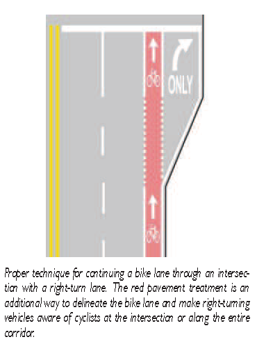
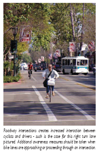
Within moderately urbanized counties such as Beaufort, there are several cases where a right-turn only lane is added at busier intersections. These right turn lanes create conflicts between vehicles that are turning and the cyclists that continue straight, in which case the vehicles are required to yield. The pavement markings shown on the right display the proper markings for a continuing bike lane between a continuing vehicle lane and a right-turn lane and demonstrate a color treatment applied to the bike lane through the intersection approach.
These are general rules for bicycle lane design, but the guide provides more detailed specifications that will be employed in the second phase of this research when needed.
3.4 - On-Street Parking
On-street parking provides convenient access to adjacent properties and can provide economic support to these properties. Since the purpose of a street is also to provide access to adjacent properties, the case can be made for retaining on-street parking, especially where quick access to nearby areas is helpful or necessary. On the other hand, on-street parking can reduce traffic flow capacity and contribute to congestion when not considered within a street's specific context. Safety is another factor to consider, as a proportion of accidents involve parked cars. However, the capacity and safety factors in restricting curb parking must be balanced with the need to maximize curb parking for adjacent properties.
3.4.1
Parking Configurations: On-street parking can come in two forms: parallel and angled parking. Arranging parking at an angle to the curb results in more parking spaces per foot of curb than parallel parking, and the increase in spaces becomes greater as the parking angle increases. As the parking angle increases, though, there is a corresponding need for vehicle-maneuver space. With parallel parking, there is more tendency to poorly align a vehicle with the painted lines, effectively occupying two parking spaces.
An emerging form of parking configuration takes conventional angled parking and reverses the direction of entry, requiring drivers to advance past a space and maneuver into it in reverse. Though initially unusual to drivers' accustomed to either conventional angled parking or the multi-point maneuvers of parallel parking, recent applications of this method of parking have proven successful and popular. While use of the adjacent travel lane for maneuvers presents the same capacity issues as front-in angled parking, drivers have use of their rearview mirrors when backing into a space, and, after advancing cautiously to exit the space, can look past adjacent parked vehicles to monitor for oncoming traffic in the travel lane.
The table below outlines the advantages and disadvantages to each, including back-in angled parking as a separate category due to the significant difference in vehicle maneuvering.
3.4.2
Parking Yield between Angled and Parallel Parking: The number of spaces available given a particular parking arrangement is, of course, dependent on the geometry of the arrangement. In essence, the number of spaces is a function of the total length available for parking less the over-lap associated with the angled vehicles, divided by the effective vehicle spacing (front bumper to front bumper). The following table lists these equations for a sample of vehicle angles and shows the number of potential spaces given a length of 100 feet available for parking. In each equation, N is the number of spaces that a given length can yield, and L is the length (in feet) of street frontage available for parking. This does not account for restrictions on parking, such as cross streets, driveway cuts, fire hydrants and loading zones.
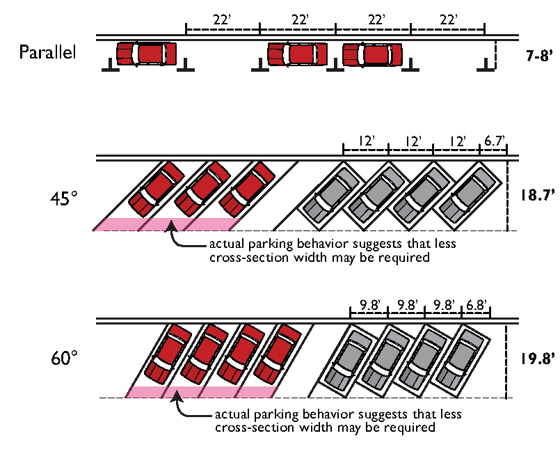
The diagram on the previous page displays various parking arrangements based on the angle of parking. In these cases, the type of parking is back-in angled parking. As mentioned previously, this type of parking helps address some of the safety issues with curb parking by allowing the driver of the parked vehicles to more readily see around adjacent parked vehicles. As is evident in this diagram, the greater the parking angle, the more spaces provided. The gray vehicles in this diagram are bound by a 8-foot-6-inch by 18-foot box, which represents the typical parking stall size for traditional parking lot configurations. The red vehicles show how drivers might actually configure their vehicles in the spaces, given that they will most likely pull in farther than the bounding box permits. This is especially true for back-in parking, where drivers will tend to rely on their rear wheel nudging the curb to identify when they are far enough into the space. Thus, it is reasonable to expect that the length of the stall could be shortened to allow more space for other street uses, or require less space to be traded off in highly constrained conditions.
3.4.3
Parking in Planter Strips and Open Drainage Areas: Parking is sometimes allowed in planter strips, which also function as stormwater collection areas in streets that do not feature curb and gutter drainage. Refer to Sections 3.5.2 and 3.5.3 for more detailed discussion of this drainage type and allowed materials to use in drainage areas when parking is to be accommodated.
3.5 - Stormwater Drainage
Coastal communities throughout the United States have adopted policies and standards promoting low-impact development (LID) intended to achieve better stormwater control and to improve the quality of stormwater run-off from developed areas. Many new street developments in Beaufort County already utilize LID techniques, which are especially relevant in a location with frequent precipitation, high groundwater levels and soils that facilitate quick infiltration. This involves reducing road and driveway widths, reducing parking areas or locating parking on permeable surfaces, and using curb-and-gutter drainage only when needed.
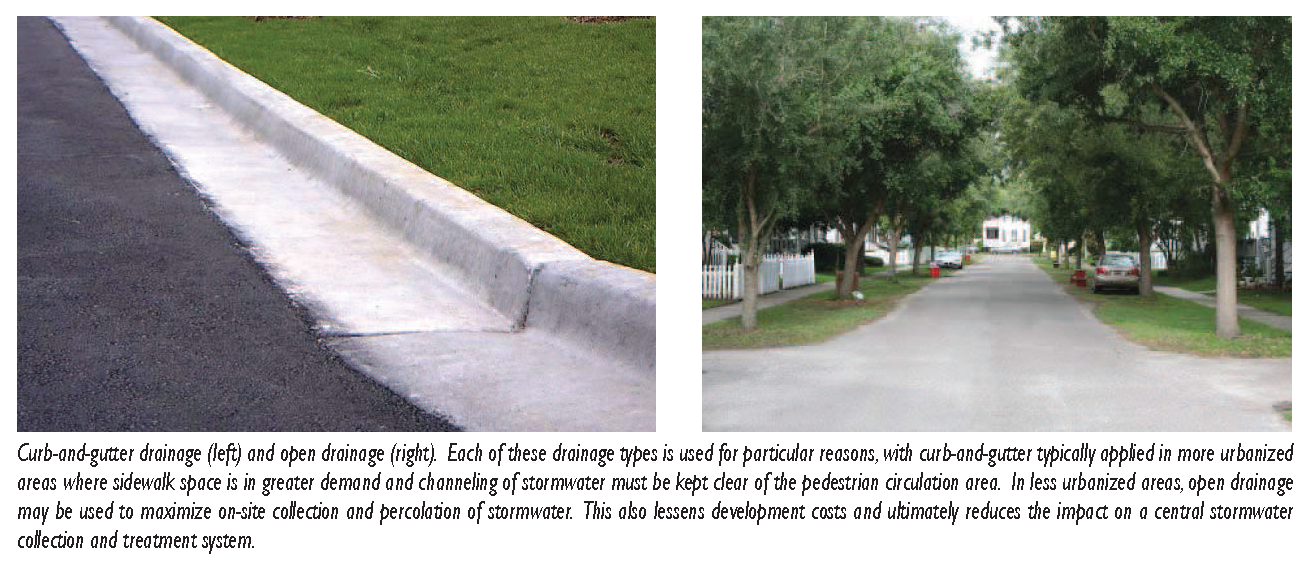
As discussed in the following sections, two principal types of drainage are to be used in Beaufort County: Standard curb-and-gutter drainage and open swale drainage. Valley gutters, a form of curb-based drainage that keeps a lower street profile and eliminates a need for curb cuts for driveways and cross-streets, are discussed as a potential form of curb-and gutter drainage to be used only in special cases.
3.5.1
Curb and Gutter: Curb and gutter drainage is commonly found in urban areas and newer development where underground stormwater collection infrastructure has been provided. It serves multiple functions, chiefly channeling stormwater flow on streets for collection through drainage inlets, delineating the roadway space from travel lanes and parking areas to the sidewalk, and facilitating street sweeping. This is most important in commercial districts, especially in the Downtown and Neighborhood Main Street districts as described in other sections of the Code and in Section 3.9 of the Technical Manual.
The AASHTO Green Book provides guidance on the types of curb-and-gutter sections available for use.
3.5.2
Open Drainage: Open drainage is often used in coastal areas such as Beaufort County where high water tables and frequent rainfall often exhaust the capacity of stormwater infrastructure. Growing LID practices have utilized certain forms of open drainage in order to reduce the impervious surface area and to maximize on-site retention.
Per existing County standards, swale drainage is allowed only when the high water table level is at least one foot below the invert of the swale. Swales used for water quality control must meet all County standards for stormwater best management practices.
3.5.3
Parking in Open Drainage:
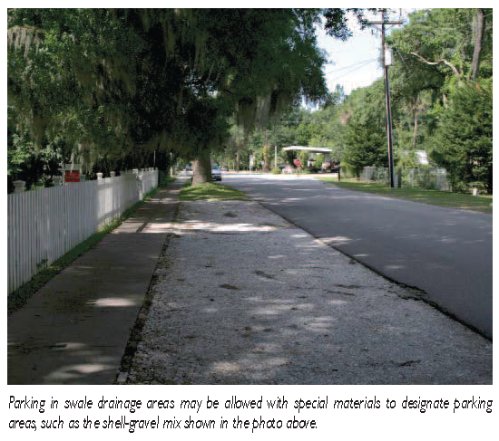
As mentioned in Section 3.4 and as detailed in the street assemblies in Section 3.9, the open drainage areas in planter strips may accommodate parking as needed. This allows usage of already-allocated street space and permeable surface, helping to reduce over- all impervious coverage.
Care should be taken to preserve overall street character and aesthetics. If sod or grass coverage is to be used, the maintenance and upkeep should be coordinated with places where parking is to be allowed so that sod used for parking is not degraded disproportionately to the rest of the street. For this reason, gravel or other permeable surfaces are often used, as they help to delineate parking and offer greater durability than a grass surface.
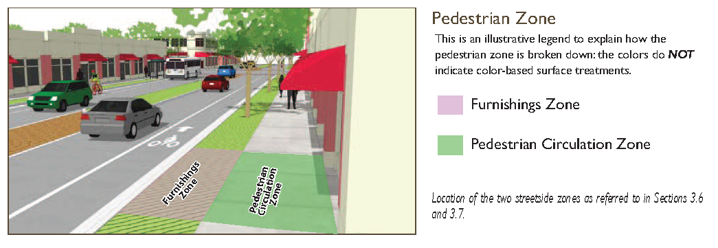
3.6 - Streetscape and Street Furnishings
The furnishing zone is the portion of the street cross section that accommodates street trees, light posts and, as needed, other utility structures and facilities. In general, a minimum of 1.5 feet of this zone should be reserved for horizontal clearance from the back of curb. Widths should be provided so that pedestrians are also not immediately in contact with tree trunks and other vertical elements, especially when constrained widths mean that the circulation area of sidewalks (see Section 3.7) may be narrow. Trees should generally be planted in the center of this zone's width.
3.6.1
Street Trees: Street trees do much to contribute to the character of Beaufort County streets. They provide shade, assist with stormwater infiltration and management, and define spaces within the public realm. Street trees include significant canopy trees, long-lived, tall trees (often Oak or Live Oak species) that form the forest canopy, and a variety of shade trees appropriate for urban spaces.
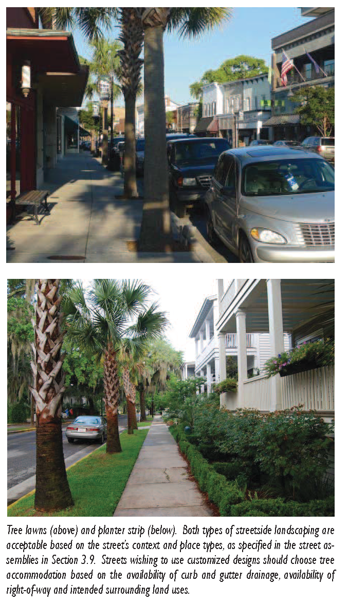
Trees should typically be planted between 20' and 35' on center to provide a consistent shade canopy, and are typically configured in Tree Lawns/Wells or along Parkways/Planter Strips.
The Beaufort County Code of Ordinances (Chapter 106, Zoning and Development Standards, Appendix E, Tree and Plant List) provides a list of street trees commonly found in the Lowcountry region and considered acceptable for planting on streets and in new development sites.
3.6.2
Tree Lawns/Wells: Tree wells are intended for use in urban districts where a continuous hardscaped surface continues from the outer edge of the sidewalk to the back of curb. They contain the area used for street trees and feature a structure that channels tree root systems.
In general, streets using tree lawns must preserve at least four feet of cross-section with for the tree lawn. Trees typically grow more successfully if they are allowed five feet or more.
3.6.3
Parkways (Planter Strips): In Beaufort County, even in significant portions of its municipalities, the rural and small-town character has been defined in part by the use of planter areas for street trees and other landscaping. In many locations they are even used for on-street parking, greatly increasing the amount of permeable surface for stormwater infiltration. Planter Strips in urban areas are typically 5' minimum width; in more general or rural areas they may be 8'—10' in width. They are likely to be used and are indeed prominently featured in the as-of-right allowed street design assemblies in Section 3.9.
3.7 - Sidewalk (Pedestrian Circulation Zone)
The walk zone is the primary passing and circulating area for pedestrians. Widths are suggested in specific cross sections, with particular regard to surrounding land use context and the needs that that land use may suggest for pedestrian activity.
The circulation area of sidewalks must, per requirements of the Americans with Disabilities Act, have a minimum passable width of 36 inches (3 feet). As certain usability factors suggest that additional space is needed to truly accommodate persons with disabilities, a minimum width of 5 feet is required per this Code. When no landscape area is provided, the sidewalk must be a minimum width of 7 feet.
3.7.1
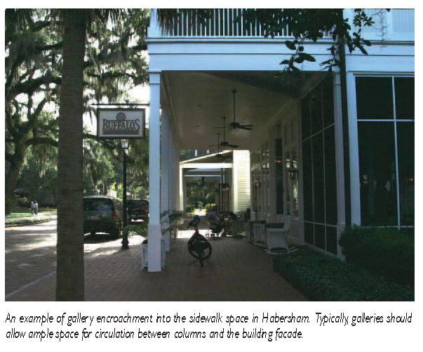
Gallery and Arcade Encroachments Over Sidewalks: In certain transect zones and street types, buildings may feature upper-floor outdoor gallery space, allowing a veranda auxiliary space adjacent to the building facade. The structural needs of this addition require encroachment into the space above sidewalks.
Two such building features are discussed in more detail in the primary sections of the Code: Gallery encroachments and arcade encroachments. In both cases, the main facade of the building is at the frontage line and the gallery element overlaps the sidewalk. The primary difference between the two is the minimum depth requirements for the gallery space, and the implications these have for sidewalk width. This type is intended for buildings with ground-floor commercial uses and may be one or two stories. The gallery should extend far enough from the building to provide adequate protection and circulation for pedestrians and extend close enough to the curb so that a pedestrian cannot bypass it.
3.8 - Curb Radius and Clear Sight Distance
Sight distance is the length of roadway visible to a motorist. This term usually refers to how far a motorist approaching an intersection can see in terms of crossing traffic. With regard to subdivision design, transportation engineers typically consider two different types of intersection sight distance, and each has particular roadway design implications:
•
Stopping sight distance: Length of visible roadway that allows a driver traveling at the design speed to see obstructions in the road and have sufficient time to stop.
•
Intersection sight distance: Also referred to as a clear sight triangle, this is the distance in advance of an intersection that is free of obstructions and that allows a driver to determine whether or not the intersection is safe to maneuver. It is essentially the stopping sight distance with the addition of a distance during which a driver could see an approaching vehicle at an intersection and determine whether to begin stopping. The distance is determined by the traffic control at the intersection, the design speeds of the intersecting roads, and the design of the intersection. Intersection sight distance is also referred to as an intersection sight triangle or a clear sight triangle. In the interest of clarity and consistency this module uses the term clear sight triangle to describe intersection sight distance.
Sight distance regulations are typically specified when subdivision design is being reviewed by permitting agencies, though local government regulations tend not to specify whether or not particular sight distance standards are intended to disallow on-street parking in perpetuity. The main reason for restricting on-street parking at intersections is to improve sight distance. Conventional engineering standards require minimum clear sight distance at roadway intersections to allow for unobstructed view of opposing and intersecting traffic. This distance is calculated based on stopping sight distance, or the distance required for a vehicle to come to a full stop. This is dependent on the vehicle's operating speed. Faster speeds along a roadway require a longer stopping sight distance.
3.8.1
Calculation of Sight Distance: Many communities throughout the United States have adopted standards that restrict on-street parking near intersections, partly because of requirements related to appropriate sight distance for the design speed but mostly because of a need to keep the actual intersection area (defined as the space between corner curb radii and the adjacent street lengths where pedestrian crossings are placed) clear of obstructions to facilitate turning vehicles. Based on case examples throughout the United States, the standard distance between the intersection and the first parking space allowed in residential streets across the country ranges from 20' to 50'.
Traditional neighborhood developments such as Habersham have sought to emphasize street design and urbanism as means of controlling driver speeds; this in turn reduces the need for long sight distances. Part of this is through reducing the design and posted speed of the roadway through narrowing lanes and introducing traffic calming measures. This points to a set of assumptions used in conventional roadway design and engineering that are not congruous with these environments. In the United States, per AASHTO Green Book guidance, stopping sight distances have been calculated with a reaction time, beginning with the time a motorist perceives a vehicle or other obstacle and ending when the motorist actually begins to apply the vehicle. This time is measured on average at 2.5 seconds. Assuming a roadway speed of 25 miles per hour, the required sight distance for stopping would be calculated from the following formula:
![]()
where t equals the brake reaction time (assumed to be 2.5 seconds), V equals speed (in miles per hour) and a equals the rate of deceleration.
The United States guidance has been developed from research largely based on highway conditions, where typically higher travel speeds and a less pronounced relationship between the street and surrounding buildings have led to more time to respond to potential conflicts while moving. However, methods of measuring this in other parts of the world have sought to identify an expression of driving and braking conditions closer to those experienced in place-based urban development. The United Kingdom's Manual for Streets uses an approach more closely oriented to residential neighborhoods and the lower speeds that they are expected to carry. Instead of a 2.5-second reaction time, the UK policy uses a minimum reaction time of 0.67 seconds and calculates a different formula:
![]()
where V equals speed (in meters per second), t equals the difference between driver perception and reaction time, and d equals the rate of deceleration.
This is based on an assumption that cars can actually stop in shorter distances at a given speed, but that certain environmental factors that control speeds (such as on-street parking and surrounding building form) raise driver awareness to make this shorter stopping distance much more feasible. Converting metric to English units and computing both formulas using a 20-mile-per-hour speed, the Green Book formula suggests a length of 115 feet of stopping distance and the UK formula suggests a length of 60 feet. In addition to using the UK standard on the basis of its being more responsive to neighborhood conditions, this manual allows designers to treat the stopping sight distance the same as intersection sight distance, as the street design proposed for non-thoroughfare streets in places of character is intended to control speeds to 25 miles per hour or less and because the presence of on-street parking and narrow street widths is expected to raise motorist awareness and make shorter stopping distances more feasible than in a higher-speed environment.
3.8.2
Sight Distance and On-Street Parking: Typically, subdivision regulations standards do not differentiate between required sight lines and on-street parking. It is the purpose of subdivision regulations and standards to establish the sight lines to ensure that buildings or other major obstructions cannot be placed in a driver's view by virtue of the way that land is subdivided. Parking regulations typically address the location of vehicles in public rights of way and are intended to prohibit the use of public parking space for long periods of time or at certain periods when street maintenance is necessary. The two are not assumed to be one and the same, but there is commonly an overlap in the two different purposes. In local parking ordinances throughout the United States, far more flexibility is given in parking along local streets than these clear sight distance requirements would suggest. In many cases, parking is allowed in an area specified in the same code of ordinances as lying within the clear sight triangle. The parking regulations that enable this do specify restrictions on parking in intersections and on approaches to crosswalks, with several of the following standards and specifications commonly occurring:
•
Parking is prohibited in intersections (typically defined as the space extending inward from the outer ends of the curb radii).
3.9 - Allowed Street Assemblies for Transect Zones
Of the design components and parameters in Sections 3.2 through 3.8, the specific cross-section designs in this section are to be allowed as-of-right in development applications. The matrix on the following page details specific values for different parameters, and the specific section diagrams on the subsequent pages graphically depict the section layouts.
Cross-sections are defined based on the five principal transect categories used in the Code. Although there is over-lap between many different cross-sections, they are generally intended to correspond to the character, form and intensity of development as it occurs in each of these transect divisions. Use of streets intended for one district is allowed in another district provided that such district is "adjacent" to the first district on the Code transect. In other words, streets for the Neighborhood Main Street transect district may be used in a Neighborhood Center district, but they may not be used in the Neighborhood General district.
The table on the following page also provides guidance on potential exceptions. These relate primarily to the width of street travel lanes, the use of parking, and the use of valley gutters for drainage. The following points should be considered by development applicants and reviewing agencies in the allowance of these exceptions.
•
Use of 12-foot travel lanes is typically not necessary in urban and neighborhood contexts. This width may be used on collector roadways in certain transect districts when the technical review committee demonstrates a need for emergency vehicle clearance or other such critical (and exceptional) need for vehicle passage that may be compromised by narrower lanes.
•
Use of 9-foot travel lanes is atypical outside of traditional neighborhood developments. It is allowed when applicants can demonstrate that these lane widths do not compromise the passage of emergency response vehicles. If 9-foot lanes are used, the development review agency may require that on-street parking widths be increased beyond their default, but not to be wider than 7.5 feet.
•
Use of "swale parallel" parking in a Neighborhood Main Street transect district requires the streetscape to use gravel, compacted soil, or another non-grass material for actual parking spaces. This should be configured to facilitate stormwater distribution out of parking spaces.
•
Valley gutters are intended to separate travel lanes from the parking area, or from the sidewalk directly. Their use must demonstrate that there is adequate capacity in a master stormwater system so that sidewalks do not experience flooding. Street designs that collect stormwater within the width of the street designated for on-street parking (whether parallel or angled) through a low meeting point of two cross-slopes, as is done along portions of Paris Avenue in Port Royal, will be considered a use of valley gutters.
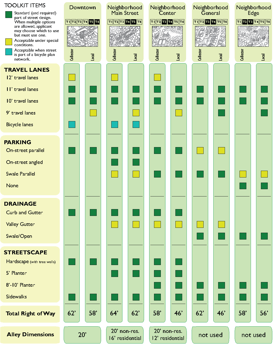
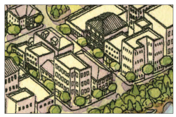
3.9.1
Downtown Streets: Streets in downtowns are primarily intended for local access and as such feature the most extensive provisions of on-street parking. Parallel parking is recommended to allow for a more compact street envelope, although as in some existing contexts (such as downtown Port Royal), angled parking may be allowed.
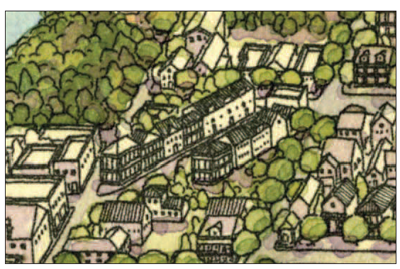
3.9.2
Neighborhood Main Street District Streets: Neighborhood main streets have a similar level of access demand to downtowns, although they generally have a less intense land development pattern. Because of the nature of hydrology in Beaufort County, these streets feature planter strips instead of hardscaped areas, though they are intended to use vertical curb and gutter for street-based stormwater collection.
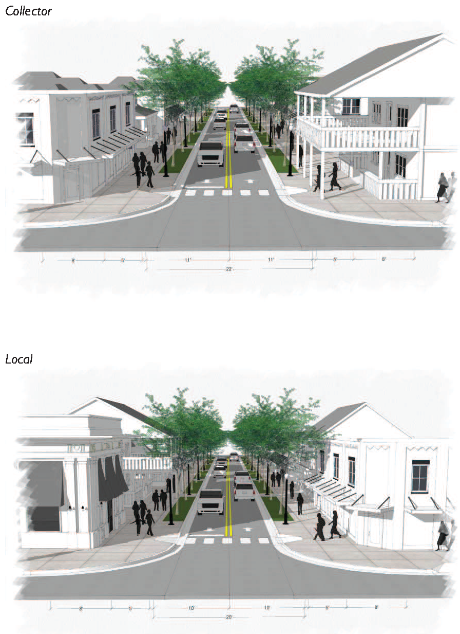
3.9.3
Neighborhood Center Streets: These are typically used in less intense development than that of Neighborhood Main Streets. A typical use scenario may be the location of a school, church, library or other community facility where regular demand for street parking can be met by what the street will allow. Curbs can be used, but so can open drainage areas.
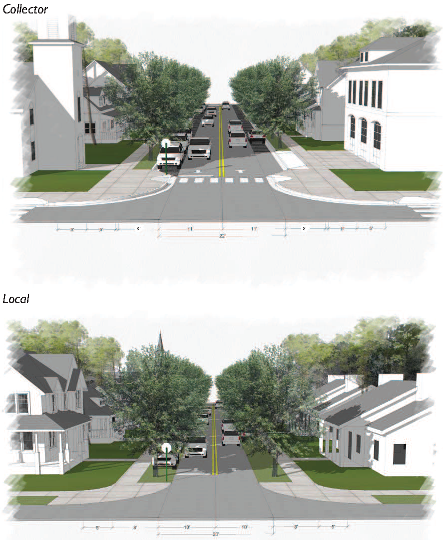
3.9.4
Neighborhood General Streets: These streets do not feature any type of curb-based drainage, al- though they do allow on-street parking in the planter strip area.
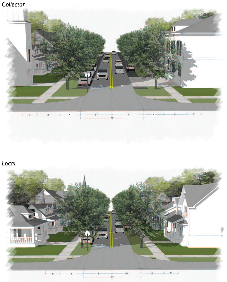
3.9.5
Neighborhood Edge Streets: These streets are generally the most rural in nature and are not designed to allow on-street parking. Depending on the capacity and availability of central stormwater infrastructure, these streets may feature a deeper swale for drainage than many of the streets in other transect districts.