Milton City Zoning Code
ARTICLE 10
- STREETS AND IMPROVEMENTS
10.1.1. - Applicability
A.
General Applicability
Conformance with this article is required, as indicated by section, except as provided for in paragraph B below.
B.
Form-Based Code Applicability
Conformance with some requirements of this article is not required when alternative standards are provided in Form-Based Codes.
10.1.2. - Purpose
This article is intended to serve the following purposes, among others:
A.
To protect and promote the health, safety, and general welfare of the city's residents.
B.
To encourage economically sound and stable land developments.
C.
To ensure the adequate provision of streets, access, utilities, and other facilities and services to new land developments in conformance with public improvement standards and regulations of the City.
D.
To ensure the adequate provision of safe and convenient traffic access, connectivity to other developments or facilities, and efficient circulation (both vehicular and pedestrian) in new land developments.
E.
To ensure the provision of needed open space and building sites in new land developments through dedication or reservation of land for recreational, educational, environmental, greenspace, bikeways and pedestrian trails, and other public purposes.
F.
To ensure equitable handling of all requests for the subdivision of land by providing uniform procedures and standards for the subdivider.
10.1.3. - Adopted Plan Conformance
A.
Proposed developments must consult the following for detailed right-of-way locations for planned or programmed projects:
1.
The Comprehensive Plan.
2.
The current 7-year Capital Improvement Plan that is part of adopted budget.
3.
The Comprehensive Transportation Plan.
4.
The most recently adopted Trail Plan/Trail Blueprint/Community Trail Prioritization Plan.
B.
The arrangement, character, extent, width, grade, and location of all streets must conform to the Comprehensive Plan and must consider their relation to existing and planned streets, topographical conditions, and appropriate relation to the proposed uses of the land to be served by such streets.
C.
Whenever a development proposes the dedication of land for public use and the Community Development Director, Public Works Director, or the appropriate agency finds that acquisition of such land is not consistent with the appropriate agency plans, policies, or priorities, the Director may either refuse to approve the plat, or require the rearrangement of lots to conform with such plans, policies, and priorities.
D.
The Director must not approve developments when the planned features specified by paragraphs A through D above are not incorporated.
10.1.4. - Right-of-Way Dedication Policy
A.
Administration
The Public Works Director and the Community Development Director will determine whether right-of-way must be reserved or dedicated to conform to this article.
B.
Rights-of-way Acceptable to the City
As developers submit plans in locations specified in Sec. 10.1.3 above, the City must require either:
1.
A reserved right-of-way on the plans and recorded; or
2.
A fee simple title or deed transfer free to the City at the approval and signing of the final plat.
Such benefit will result in impact fee credits to the developer from the Director when those improvements are determined to be system improvements.
C.
Reserved Rights-of-Way
The following applies to reserved rights-of-way:
1.
Reserved rights-of-way must be provided at no cost to the City.
2.
Reserved rights-of-way do not impact the calculation of total allowable density but do determine required setbacks and buffers.
10.2.1. - General
A.
Applicability
All developments and subdivisions must conform to the standards of this section.
B.
Land Suitability
Land subject to flooding, improper drainage, erosion, and deemed unsuitable for development in accordance with the City's standards must not be platted for any use that would continue such conditions or increase the danger to health, safety, life, or property unless steps are taken to eliminate these hazards.
C.
Conformance with Other Requirements
Every developer must install the appropriate public utility and improvements referenced in this section in accordance with the following:
1.
Any adopted State, County, and City Standard Specifications and Details.
2.
Water and sewer Regulations of Fulton County.
3.
Sec. 11.1 (Tree Canopy Conservation Ordinance).
10.2.2. - Water Supply
A.
Water supply and services shall be regulated by Fulton County or other authorized jurisdiction.
B.
Where a public water supply is not available, each lot in a subdivision must be furnished with a water supply system approved by the Fulton County health department.
C.
A separate water service connection must be provided for each dwelling unit. Meters must be located as specified by the utility company.
D.
Fire hydrants must be located and set in accordance with Fulton County and the City of Milton Standard Plans, where applicable.
E.
If a subdivision is replatted and the originally platted lot configuration is changed after the water service lines have been installed, the water system must be modified to properly serve each lot in accordance with the Fulton County water specifications.
10.2.3. - Sanitary Sewer
A.
Sanitary sewer systems and services shall be regulated by Fulton County or other authorized jurisdiction.
B.
Whenever the installation of a sanitary sewer is permitted by Fulton County, no new street may be paved without first installing the sewer in accordance with the requirements of the sewer specifications of the Public Works Department and the Fulton County or other authorized jurisdiction sewerage regulations.
C.
If a subdivision is replatted and the originally platted lot configuration is changed after the sewer service lines have been installed, the sewer system must be modified to properly serve each lot in accordance with Fulton County or other authorized jurisdiction sewer specifications.
10.2.4. - Stormwater Facilities
A.
General
1.
Stormwater management facilities must conform to Sec. 11.4. (Post-Construction Stormwater Management for New Development and Redevelopment) better site designs, and nonstructural stormwater management practices are required unless exempted by the Director as provided in Sec. 11.4.1.G.
2.
Engineering and construction must be carried out in a manner as to maintain water quality and rate of runoff to protect neighboring persons and property from damage or loss resulting from excessive stormwater runoff, pollution, soil erosion or deposition upon private property or public streets of water-transported silt and debris.
3.
Proper drainage plans must be submitted for review by the Director. These plans must be prepared by a professional engineer or landscape architect, currently registered to practice in the State, with stamp affixed.
4.
The plans must be accompanied by profiles of natural and proposed drainageways, including:
a.
Cross sections.
b.
Downstream analysis.
c.
Drainage swales.
d.
Storm pipes.
5.
Shared stormwater management facilities are encouraged.
B.
Design for Stormwater Management
1.
Grading and drainage plans required by this section must be accompanied by a hydrology study that complies with Sec. 11.4 (Post-Construction Stormwater Management for New Development and Redevelopment).
2.
The purpose of the hydrology study is to:
a.
Identify the surface water runoff quantity, quality and rate;
b.
Establish runoff management control requirements for the development;
c.
Furnish all design calculations for the management control facilities, surface water conveyance systems (before and after development runoff); and
d.
Furnish design calculations for the volume of storage required.
3.
A schedule indicating the timing for planting or mulching for temporary or permanent ground cover must be submitted with these grading and drainage plans.
4.
Erosion control devices must be installed before starting grading and construction; the engineer must state this requirement on the engineering drawings.
5.
To ensure full compliance with the approved construction plans, final plat approval will be withheld until "as-built" drawings, prepared by a professional engineer or landscape architect currently registered in the state, have been submitted and approved by the Director in accordance with Sec. 12.6.5 (Final Plat Approval). No occupancy permit will be issued until released by the Director.
6.
The owner must maintain the storm drainage facilities during grading and construction, and for 18-months bond duration after final plat approval. Maintenance will be construed to include preserving the enclosing walls or impounding embankment of the detention basin and permanent sedimentation ponds and security fences, in good conditions; ensuring structural soundness, functional adequacy, and freedom from sediment of all drainage structures; and rectifying any unforeseen erosion problems.
C.
Detention/Retention Design
1.
General
a.
Installation of properly functioning detention facilities, including outflow control devices, is the responsibility of the owner. If any control devices are damaged or destroyed during grading or construction, all processes must cease until such devices are restored to their functioning capability. The owner, through application for grading or construction permits, accepts the responsibility of maintenance of the control devices.
b.
When serving more than three lots, except when all the single-family residential lots are each a minimum of 3 acres in size, detention ponds, retention ponds, and water quality features (including all required access easements, landscape strips, and fences) must be located on a separate parcel where no home can be constructed. This parcel must be owned and maintained by a homeowners' association or the owners of the lots being served by this pond. The parcel must have a minimum of 20-foot-wide continuous access to a public or private street in a manner that allows access and maintenance of this parcel. In addition, this parcel will not be required to meet the normal lot standard.
2.
Design standards. Above-ground stormwater management facilities must meet the following standards:
a.
Provide a 20-foot graded access easement.
b.
Provide 10-foot access easement for maintenance.
c.
Provide 6-foot-high fence.
d.
Be located in the least conspicuous area of the site as engineering standards allow.
e.
Be designed to create a natural look.
f.
Be surrounded by a minimum 10-foot-wide landscape strip planted to buffer standards with evergreen plantings exterior to any required fence and/or required access area, except as otherwise approved by the Director under Sec. 10.2.4.C.2.g immediately below.
g.
In lieu of Sec. 10.2.4.C.2.f immediately above, the 10-foot-wide landscaped strip is not required to be planted to buffer standards when the following standards are met:
i.
The minimum 10-foot-wide landscape strip is incorporated into a larger open space.
ii.
The open space containing the stormwater facility is designed and stamped by a Landscape Architect licensed in the State.
iii.
The stormwater feature is designed as formal or natural amenities for the open space.
iv.
The stormwater features does not constitute more than 25% of the required open space.
3.
Alternative design standards. Applicants are encouraged to carry out innovative detention/retention layouts that are intended to make such facilities an attractive amenity or focal point to the subdivision. To achieve that, the Director may approve the following alternative design standards in lieu of those in Sec. 10.2.4.C.1 and Sec. 10.2.4.C.2:
a.
Such alternative design shall provide for an attractive layout and means for detaining, retaining, and/or moving water.
b.
The design shall follow the natural landforms around the perimeter of the basin. The basin should be shaped to emulate a naturally formed depression.
c.
Redistributing soils from basin construction to create natural landforms around the perimeter of the basin is encouraged. These forms shall be located strategically to filter views or redirect and soften the views from residential areas.
d.
Side slopes of basins must not exceed one foot vertical for every 4-feet horizontal. Where possible, side slopes should be varied to imitate natural conditions. Associated natural landforms should have side slopes that do not exceed one foot vertical for every 3 feet horizontal to accommodate lawn maintenance equipment. Varied slopes will be encouraged.
e.
The applicant is encouraged to use plant materials that naturally grow in the area. Trees and shrubs shall be grouped in informal patterns to emulate the natural environment. The intent is to soften the views of these basins.
4.
Design guidelines. The Director may issue design guidelines illustrating details of the standards in Sec. 10.2.4.C.2.d.
D.
Storm Drain Stenciling/Identification
1.
All residential subdivision and commercial entity storm drainage structures or facilities (e.g., catch basins, storm sewer inlets, culverts, impoundment facilities, manholes, and other facilities that convey stormwater runoffs) must be properly identified.
2.
Each drainage structure must be identified with the use of a City of Milton branded lid.
10.2.5. - Plans and Construction
A.
Sanitary and Storm Sewer Easement
1.
Permanent sanitary and storm sewer easements must meet the standards in the following table:
2.
No fill may be placed on a sanitary or storm sewer easement without approval by the Public Works Director. All sanitary manholes must extend to the ground surface. All easements terminating on a parcel must extend to the property line.
3.
No retaining wall, building, pole, sign or other vertical structure may be constructed in sanitary and storm sewer easements, including vehicular access easements around structures, without approval from the Public Works Director. No fence may be placed across sanitary or storm sewer easements without gates to which the City or Fulton County has full access. No planting may take place in a sanitary or storm sewer easement that will impede vehicular access along the easement or endanger the pipeline. No surface water may be impounded on a sanitary sewer easement. No other pipeline or utility may be placed in a sanitary or storm sewer easement without approval by the Public Works Director.
4.
Each lot or parcel of land in a subdivision must have a separate sewer connection terminating at the easement limit or right-of-way limit with a vertical cleanout pipe. No connection of the public sewerage system may be made except at a sewer connection approved by the Public Works Director.
5.
No surface water, groundwater, storm drain, gutter, downspout, or other conveyance of surface water or groundwater may be discharged into the sanitary sewer.
B.
No sanitary sewer may be accepted by the Fulton County without an "as-built" drawing showing the horizontal and vertical alignment of the sewer system, the locations of all manholes, sewer connections, piping materials, required easement limits and junctions, and property lines. This should be provided in the form of plans, profiles, and plats; when possible, an electronic copy of the required data, compatible with the City's GIS, should be submitted.
C.
No storm sewer may be accepted by the City without an "as-built" drawing showing the horizontal and vertical alignment of the sewer system; the locations of all manholes, junctions, detention ponds, retention ponds, and sewer system outfalls discharging into ditches or creeks; sewer connections, piping materials, required easement limits; and property lines. This information must be provided in the form of plans, profiles, details, sections, and plats and, when possible, in an electronic form compatible with the City's GIS and the applicable Public Works Department database.
D.
In the case of single-family residential subdivisions, by written application, the owner may request that the City assume partial maintenance responsibility of drainage facilities, effective after the expiration of the initial maintenance 15 months. Within 60 days after receipt of such application, the Director must respond in writing to the owner/applicant. Such response must set forth additional terms and conditions for acceptance. However, maintenance by the City will be limited to ensuring the functional adequacy of such drainage structures. The maintenance responsibility will remain partially with the homeowners' association unless and until, and only to the extent that, the homeowners' association is expressly relieved of such responsibility pursuant to and in accordance with a written instrument signed by the Director. Appropriate easements must be executed and recorded pursuant to this subsection. For all other types of development, responsibility for maintenance of storm sewer system and detention ponds including, but not limited to, periodic silt removal to maintain functional integrity, will remain the owner's responsibility. Maintenance responsibility will constitute an obligation running with the land and must be binding upon the owner's executors, administrators, heirs, successors, and successors-in-title. The owner/developer must provide stabilization, including vegetation, and installation of security fences for safety purposes at detention facilities, as prescribed, before approval of the final plat by the Director.
E.
Any single-family detached home which involves less than 10,000 square feet of cleared area, and all impervious surface areas combined, is exempted from the provisions of a hydrology study. In no such case, however, may grading involve over 25% of the total land area.
F.
All engineering and construction, regardless of whether such engineering or construction is being accomplished on public land or on public easements, must meet the minimum requirements of these regulations.
10.2.6. - Monuments and Iron Pipes
A.
The accurate location, material, and size of all existing monuments must be shown on the final plat, as well as the future location of monuments to be placed after street improvements have been completed following Chapter 180-7 (Technical Standards for Property Surveys) of the Georgia Administrative Code.
B.
The direction and distance from one Fulton County or GDOT GIS Monument to a point on the boundary of the individual survey must be provided.
10.2.7. - Utility Service
A.
Underground Utilities Required
All existing and proposed utilities, including all electrical, telephone, television and other communication lines, both main and service connections, serving or having capacity of 69 KV or less, abutting or located within a requested land disturbance area, must be installed underground in a manner approved by the applicable utility provider and in compliance with the City's right-of-way and erosion control regulations, if applicable.
B.
Existing Overhead Utilities
Lots that abut existing easements or public rights-of-way, where overhead electrical or telephone distribution supply lines and service connections have previously been installed, may be supplied with electric and telephone service from those overhead lines, but the service connections from the utilities' overhead lines must be installed underground. Should a road widening, an extension of service, or other such condition occur as a result of the subdivision and necessitate the replacement or relocation of such utilities, such replacement or relocation must be under ground.
C.
Application Requirements
Applicants for subdivisions must:
1.
Submit drawings of the subdivision layout showing locations of underground electrical cable, transformers, and other related fixtures, in accordance with the standard plans. These drawings must be approved by the City before installation of the underground utility and before a building permit can be issued.
2.
Pay all cost for poles, fixtures, or any related items of materials necessary for the installation to the utility company.
3.
Submit proof of payment for complete installation.
4.
Have an agreement with the appropriate power company for complete maintenance of all installations and provide proof of payment.
D.
Streetlights and Pedestrian Lighting
1.
Streetlights and pedestrian lights must be provided by the developers of all new subdivisions, except land subdivided under the provisions of a minor plat. All subdivisions must install streetlights where those street lights are required along the frontage of a property based on the requirements of the zoning district. At the time of, and as a requirement of, submission of a final plat, the developer must:
a.
Submit a drawing of the subdivision's layout showing locations of streetlights and required pedestrian lights. This drawing must be approved by the Director before obtaining any building permit within the subdivision. The layout must be shown on the land disturbance permit. Fixtures and standards/poles installed or used must be approved by the City and by the utility company which must be responsible for the maintenance of the facilities.
i.
Streetlight fixtures must be mounted 30 feet above the ground and must have appropriate arm length to place the light over the street. Arms must be at least 5 feet long. Post-top luminaries may be permitted when approved by the City, providing they comply with any applicable requirements of Article 2 through Article 8. Fixtures must be located no more than 300 feet apart and at least one light must be located at each street intersection within the subdivision. When a subdivision is in an overlay district or Form-Based Code, light standards must comply with the overlay or Form-Based Code.
ii.
Pedestrian lights must be installed as required by overlay districts, Form-Based Codes, or the specific zoning case.
b.
Pay all costs for standards/poles, fixtures and any other related items or material necessary for installation.
c.
Submit proof of payment for complete installation to the Public Works Director.
d.
Submit a copy of an executed agreement with the utility company for complete maintenance of all installations.
e.
When at least 50% of the dwelling units in the subdivision have been occupied, submit a request to the Public Works Director for the City to assume maintenance responsibility and make the monthly payments to the utility company for electrical energy for each streetlight.
10.3.1. - General
A.
Applicability
All developments must conform to this section.
10.3.2. - Blocks
A.
Block Layout
The lengths, widths, and shapes of blocks must be determined with due regard to:
1.
Provisions of adequate building sites suitable to the special needs of the type of use contemplated;
2.
Zoning requirements as to lot sizes and dimensions unless a planned unit development is contemplated;
3.
Needs for convenient access, circulation, control, and safety of street traffic; and
4.
Limitations and opportunities of topography.
B.
Residential Blocks
1.
Residential blocks must be wide enough to provide two tiers of lots, except where fronting on streets classified as a collector street or higher or prevented by topographical conditions or size of the property. The Director may require or approve a single tier of lots of minimum depth to overcome specific disadvantages of topography, orientation, and property size or when the public health, safety, and welfare demand.
2.
Residential blocks must be arranged and designed so their use for through traffic is discouraged.
C.
Cul-de-Sac Blocks
Cul-de-sac streets must be designed so that the maximum length is 600 feet. The Public Works Director has the authority to approve longer cul-de-sac streets when the site's size, shape, topography, natural features, or other conditions render this requirement unreasonable.
D.
Minimum Setback for New Streets
New public and private streets rights-of-way or access easements must be at least 50 feet from any peripheral property line adjoining agricultural districts and residentially zoned property unless interparcel access is required by Sec. 10.3.6 or otherwise provided.
10.3.3. - Gated Communities
Gates installed in subdivisions with more than one lot must comply with the following:
A.
Plan approval and a permit must be obtained before installing any gates. The permit fee will be calculated in accordance with applicable building permit fees. Gates must not prohibit public access to dedicated areas as defined within these regulations.
B.
Gate must not be installed in a City right-of-way.
C.
Gates must not create a dead-end street without first installing a turnaround conforming to the City's standards on a dead-end street exceeding 150 feet in length.
D.
Gates must provide for stacking distance, turnaround and emergency vehicle access, as required by the Director.
E.
Gate permits may be denied based on traffic conditions, interconnectivity needs, and when not in compliance with adopted guidelines.
10.3.4. - Access
A.
General
1.
Unless otherwise herein noted, every subdivision must be accessed by public streets, private streets, or modified, single-family residential, access or shared (private drive) driveways in accordance with the following:
a.
The proposed access must meet City standards and regulations.
b.
No access road intended to be private may be extended to serve property outside that development, unless approved by the Public Works Director.
2.
When land is subdivided, the created parcels must be arranged and designed to allow for the opening of future streets and provide access to those areas not presently served by streets.
3.
Subdivisions must not be designed to completely eliminate street access to adjoining parcels of land without current street access.
4.
No owner or developer shall construct or maintain a drive, yard, or lot constructed of gravel, pebbles, or stone in such a manner that vehicles cause loose stones, pebbles or gravel to be thrown onto the adjacent street or sidewalk.
B.
Private Access
1.
In residential subdivisions, private access must be maintained by a mandatory homeowners' association. Documents of incorporation must be submitted to the Director for review and approval before recording the final plat.
2.
The subdivider must provide all necessary easements for ingress and egress for police, fire, emergency vehicles and all operating utilities.
3.
The final plat of any subdivision with private streets or access must clearly state that such streets or access are private.
C.
Minor Plats
In subdivisions approved as a minor plat and where the minimum lot size is 3 acres or greater the lots may be served by a modified, single-family residential, access or shared (private drive) driveway designed to Fire Department access standards. When such access is provided the minor plat must clearly indicate the necessary access easements. The access easements must be privately maintained.
D.
Driveways
When land is subdivided, driveway access points must not increase from the number allowed under existing conditions without approval from the Public Works Director.
E.
Single-Family Lot Access
Any subdivision of land for single-family dwellings that have new roads providing direct access to the lots within the subdivision will be limited to newly constructed internal roads.
F.
Shared Access
Lots may share access as provided herein. Lot frontage and access do not necessarily have to be along or front the same public street, if approved by the Director.
G.
Subdivision Design
The Director may encourage the design of the subdivision in a manner that will:
1.
Enhance traffic circulation and other community needs;
2.
Encourage pedestrian traffic to schools, parks, existing and planned greenspace corridors, and neighborhood shopping centers;
3.
Reduce impacts on streams and lakes;
4.
Reduce unwanted noise, lights on neighboring lots; and
5.
Discourage speeding on local streets.
H.
Temporary Dead-End Streets
Where a subdivision contains a dead-end street or stub street other than a cul-de-sac, the subdivider must provide a temporary cul-de-sac within the right-of-way. Where a temporary cul-de-sac is required, the subdivider must maintain and construct the final street connection or turnaround, as required.
I.
Frontage Streets
Where a subdivision abuts or contains an existing or proposed street classified as a collector street or higher, the Director may require frontage streets. Double frontage lots may be required to have screening and no access easements along lot lines fronting on arterials or collector streets. Deep lots with rear service drives, or other treatment as may be necessary for adequate protection of residential properties, may be required to afford separation of through and local traffic.
10.3.5. - Lots
A.
The size, shape, arrangement, and orientation of every lot is subject to the Director's approval for the type of development and use contemplated in order to achieve the purposes of this Article 10. Proposed internal lot lines (not on the street side) must not be curved.
B.
Every lot must conform to the dimension, area, and size requirements of the applicable zoning district. In cases of hardship where lot requirements cannot be met, a variance may be requested in compliance with Article 12.
C.
Lots not served by a public sewer or community sanitary sewerage system and public water must meet the dimension and area requirements of the Fulton County health department. See Sec. 10.2.3 for additional sanitary sewer requirements.
D.
Double frontage lots are prohibited, except as approved by the Director where such lots are essential to separate residential development from traffic arteries or to overcome specific disadvantages of topography, orientation, and property size. A planted screen may be required along lot lines abutting a traffic artery or other use that would have potential negative impact.
E.
Each lot must have direct access to an abutting, existing public street or to a street contained within the proposed subdivision. A connection through an approved private drive may be permitted by the Director when such connection is consistent with the purposes of this Article 10.
F.
The creation of remnant lots that are below minimum standards is prohibited, unless such lots are designated as common area on the final plat and maintained by the homeowners' association or some other entity approved by the City.
G.
Subdivisions that result in lots adjacent to or surrounding an existing or proposed lake must extend such lot lines to either:
1.
The centerline of the lake; or
2.
The centerline of a common area maintained by a homeowner's association.
10.3.6. - Interparcel Access
A.
Interparcel Access Required
Interparcel access must be provided to adjacent properties upon determination by the Community Development Director and Public Works Director that such access is in the best interest of public health, safety, or welfare.
B.
Private Streets
In residential subdivisions, where private streets are proposed, the Community Development Director and Public Works Director may require a public street for interparcel connection purposes; the Community Development Director and Public Works Director may also require a shared access upon a determination that the same is in the best interest of the public, safety, and general welfare.
10.4.1. - General
A.
Applicability
All new, reconstructed, or extended public and private streets must conform to the standards of this Sec. 10.4.
B.
Improvements
Standards for all improvements not contained in this section must conform to the requirements of Chapter 48 of the Code of the City of Milton, Georgia.
C.
Plats
Design standards identified in this section and any adopted State, County, and City Standard Specifications and Details must be observed in all plats, as approved by the Director.
D.
Fire Code Compliance
Where differences exist among this UDC and the fire apparatus code, the Public Works Director and Fire Marshal are responsible for determinations of which is the controlling requirement.
E.
Private Streets
Necessary easements for ingress and egress for police, fire, emergency vehicles and all operating utilities must be provided. If the City is ever petitioned to assume ownership and maintenance of the private streets before dedication of the streets, they must be brought to acceptable City standards subject to the approval of the Public Works Director.
10.4.2. - Creation of New Streets
A.
The Public Works Director must approve the design and construction for any new streets and roads in compliance with this Sec. 10.4.
B.
The creation of new streets and roads must conform to all rules set out in O.C.G.A. Title 32, et seq.
C.
Functional classifications of new streets and roads must be as defined in Article 13.
D.
The standard construction specifications for new streets and roads must be the current version of GDOT Standard Specifications. The English system of measurement must be used.
E.
Enforcement will be by engineering testing according to Chapter 48 of the Code of the City of Milton, Georgia on all new public or private rights-of-way before final plat approval or certificate of occupancy, whichever is appropriate.
10.4.3. - Street Types
New streets must conform to one of the following, except where otherwise allowed in Form-Based Codes.
A.
Major Subdivision Streets
The minimum requirements are as follows:
1.
Right-of-way: 50 feet.
2.
Pavement width: 24 feet back of the curb to back of the curb.
3.
Cul-de-sac:
a.
Right-of-way: 50-foot radius with an optional 10-foot radius landscape island.
b.
Pavement width: 40-foot radius to back of the curb.
4.
Sidewalks: In accordance with Sec. 10.6.3.
5.
Street trees: On both sides and in accordance with Sec. 10.4.8 and Article 11.1 (Tree Canopy Conservation).
B.
Minor Subdivision Streets
The minimum requirements are as follows:
1.
Right-of-way: 44 feet.
2.
Pavement width: 22 feet back of the curb to back of the curb.
3.
Cul-de-sac:
a.
Right-of-way: 42-foot radius with an optional 8-foot radius landscape island.
b.
Pavement width: 48-foot radius to back of the curb.
4.
Sidewalks: In accordance with Sec. 10.6.3.
5.
Street trees: On both sides and in accordance with Sec. 10.4.8 and Sec. 11.1 (Tree Canopy Conservation).
C.
Other Streets
For streets not mentioned in paragraphs A and B above, the Director will determine the required cross section. For modified, single-family residential, access or shared (private drive) driveways, the design standards must comply with this Sec. 10.4.3 and the Appendix D-Fire Apparatus Roads of the International Fire Code (latest edition). The City of Milton Fire Marshal may approve variances from these design standards provided the public health, safety and welfare is protected and the variance is in the best interest of the City.
D.
Residential Design Speed
1.
All residential streets must be designed for a maximum of 25 miles per hour.
2.
The Public Works Director may require streets that do not provide direct residential access to be designed for up to 35 miles per hour.
E.
Traffic Calming
Where proposed public streets are longer than 600 feet, traffic calming devices must be incorporated to include greenspace, islands, residential roundabouts, or other traffic calming devices as approved by the Public Works Director. The minimum distance between individual devices must be at least 500 feet, but not more than 900 feet. All measures must conform to the City's traffic calming policy.
10.4.4. - Gravel Roads
A.
Public Gravel Roads
Public gravel roads may be allowed with approval of the Public Works Director and the City Council. Public gravel roads must be constructed and maintained in accordance with the Federal Highway Administration Gravel Roads Construction & Maintenance Guide. In addition, the following standards apply:
1.
Gravel road grades must not exceed 6%.
2.
All intersections of gravel roads with paved roads require a 20-foot paved apron at the intersection, with a concrete transition strip at least 12 inches in length where the apron meets the gravel road.
3.
When gravel roads slope upward from an intersection with a paved road, the profile of the gravel road must flatten to a slope no greater than 2% for least 20 feet before the apron. The design engineer must include a ditch/swale detail with cross-section on road plans.
B.
Private Gravel Roads
Private gravel roads must be residential in nature. Private gravel roads may be permitted under the following conditions:
1.
When the projected Average Daily Trips (ADT) is less than 400;
2.
When the gravel road does not connect to more than one collector or higher classification road; and
3.
When the typical section is constructed in accordance with standards developed by the Public Works Department.
10.4.5. - Roadway Geometry
A.
Grading
The required improvements for new street grading are as follows:
1.
All street rights-of-way must be cleared and graded to standards of the Public Works Department.
2.
Finished grades must be at levels approved in accordance with the standard plans.
3.
When property adjacent to the street is not owned by the developer, the developer must obtain the necessary easements of sloping banks before submitting a land disturbance permit.
B.
Street Grades
New street and driveway grades should be as shown in the following table:
C.
Vertical Alignment
All local roads with 25 miles per hour designs must be connected by vertical crest curves with a length that is at least 12 times the algebraic difference between the rates of grade, expressed in feet per hundred. All local roads with a 25 miles per hour design speed must be connected by vertical sag curves with a length that is at least 26 times the algebraic difference between the rates of grade, expressed in feet per 100. In any case, the sight distance must meet the following minimum requirements:
1.
In proposed approaches of new streets to intersections with existing streets, there must be a suitable leveling of the street at a grade not exceeding 3% and for a distance of at least 50 feet, as measured from the back of the curb of the intersecting street.
2.
In approaches to intersections internal to residential subdivisions, there must be a suitable leveling of the street at a grade not exceeding 5% and for a distance of at least 50 feet, as measured from the center point of the intersection.
D.
Horizontal Alignments
The minimum horizontal centerline alignments are as follows:
1.
Major subdivision street designed for 35 miles per hour: 200 feet.
2.
Other major subdivision street: 100 feet.
3.
Minor subdivision street: 100 feet.
E.
Tangents
The minimum tangents between reverse curves are as follows:
1.
Major subdivision streets designed for 35 miles per hour: 100 feet.
2.
Other major subdivision street: 50 feet.
3.
Minor subdivision street, where there is no super-elevation: 50 feet.
F.
Intersections
Requirements for both internal proposed streets and proposed connections to existing City streets are covered under Sec. 10.5.
G.
Visibility
1.
Roadways must be designed so the proper sight distance is maintained.
2.
Minimum sight distance is determined by the operating speed of the road, as determined by the Public Works Department.
3.
Intersection sight distance is measured as specified in Sec. 10.5.3.H (Sight Distance).
H.
Stopping Sight Distance Visibility
1.
Roadways must be designed so the proper stopping sight distance is maintained.
2.
Minimum sight distance is determined by the design speed of the proposed road as determined by the Public Works Department.
3.
Stopping sight distance along a roadway may be no less than the following:
4.
Minimum vertical visibility for stopping sight distance along the roadway is determined by measuring between two points of which the height of the driver's eye will be assumed at 3½ feet to an assumed object which is 2 feet in height. The line of sight must remain within the proposed dedicated right-of-way, unless sufficient easements, maintenance agreements, and indemnification agreements are provided, or additional right-of-way is dedicated.
5.
Vertical visibility for stopping sight distance is measured on the centerline.
10.4.6. - Street Paving/Striping
A.
Street paving widths must conform to the minimum fire apparatus requirements.
B.
Street pavement must be installed according to adopted State, County, and City Standard Specifications and Details.
C.
Striping must be installed according to adopted State, County, and City Standard Specifications and Details.
D.
Projects that require roadway improvements must mill and repave along the improvements. The road must either be resurfaced from edge to edge, or it must be milled and repaved to the centerline. The edge of pavement must be flush with the edge of gutter for vertical curb. At least 6 inches of exposed curb must be retained.
E.
No striping should be provided on subdivision streets designed for 25 miles per hour, except for stop bars and 50 feet of double yellow centerlines, to be located at each entrance to the subdivision.
10.4.7. - Curbs and Gutters
The required improvements for curbs and gutters are as follows:
A.
Curbs and gutters installations must be in accordance with any adopted State, County, and City Standard Specifications and Details.
B.
Curbs and gutters may be waived by the Community Development Director and Public Works Director if the sidewalk along the same portion of the roadway is set back at least 12 feet from the edge of pavement and drainage is adequately addressed. Setbacks other than 12 feet may be approved by the Community Development Director and Public Works Director when conditions warrant.
C.
A graded aggregate base must be extended 6 inches beyond the new curb and gutter, per the GDOT detail.
10.4.8. - Street Trees
A.
Street trees and other shrubs that are retained or planted must not obstruct sight distances and are subject to the Community Development Director and Public Works Director's approval.
B.
When a tree is planted within the right-of-way, the species, caliper, and maintenance requirements shall be as required by the Community Development Director and Public Works Director, after consultation with the City Arborist. Consideration must be given to the zoning district requirements, Sec. 11.1 (Tree Canopy Conservation), context, engineering practices, and the public health, safety, and general welfare.
C.
Street trees must be planted behind the sidewalk for urban sections or outside of the AASHTO defined clear zone for collector or higher classified roadways, which may extend outside of the right-of-way onto personal property.
D.
Any tree within the right-of-way is subject to removal for safety reasons upon coordination of the Public Works Director and Community Development Director.
10.4.9. - Signs and Markings
A.
Conformity with MUTCD Required
All signing and pavement marking must be designed and installed in conformance with the latest edition of the MUTCD.
B.
General Provisions
1.
All signposts placed within a concrete area must have a 6-inch-wide diameter space through substructure.
2.
Traffic control signs should be installed at least 7 feet but no more than 10 feet from the ground to the bottom of the sign, and at least 2 feet from the face of curb to the closest edge of the sign, or as required by the MUTCD.
3.
As part of the land disturbance permit process, the Public Works Director will identify the number and location of required signs. Sign installations must conform to Sec. 10.4.9.C and Sec. 10.4.9.D.
4.
The applicant must maintain signs from installation to final inspection. The City may replace stop or yield signs if they have been down for more than 12 hours, to replace any other regulatory signs if they have been down for more than seven days, and to replace other signs if they have been down for more than 14 days. Such replacement will be done at the cost to the applicant of $250.00 per sign.
5.
Sign inspection must be done by the Director before acceptance of the final plat or as established by the Public Works Director. Signs should be performance bonded at the same time as the pavement at a cost of $100.00 per sign or as established by the Director. If the City has to replace any signs during the final inspection, the value would be forfeited.
C.
Signs Installed on New Streets
1.
Stop signs (R1-1)
a.
The stop sign must be installed on the right side of the approach to which it applies. Stop lines, when used to supplement a stop sign, must be located at the point where the road user should stop. Where there is a marked crosswalk at the intersection, the stop sign must be installed in advance of the crosswalk line nearest to the approaching traffic.
b.
Stop signs must be installed in a manner that minimizes the numbers of vehicles having to stop. In most cases, the street carrying the lowest volume of traffic should be stopped. A stop sign must not be installed on the major street unless justified by a traffic engineering study as recommended by the MUTCD. If two streets with relatively equal volumes and characteristics intersect, typically the direction that conflicts the most with established pedestrian crossing activity or school walking routes or the direction that has the longest distance of uninterrupted flow approaching the intersection should be stopped.
c.
All-way stops require approval of the Public Works Director and must be designed in accordance with the MUTCD.
2.
Yield sign (R1-2)
Yield signs must be installed when there are right turns at an intersection that are channelized apart from the through and left turn movements with a striped or raised island. In addition, yield signs must be installed on each approach of a roundabout.
3.
Speed limit sign (R2-1)
Speed limit signs must indicate a 25 MPH speed limit for streets internal to residential subdivisions, unless it is a local collector road for the development, and then it must be no higher than 35 MPH. For neighborhood settings, only one speed limit sign must be installed at each project entrance or at the points of change from one speed limit to another. This sign should be installed no less than 100 feet from the entrance of the subdivision, but no more than 500 feet from the entrance.
4.
Street name sign (D3-1)
a.
Street name signs must be installed at every intersection. Overhead street name signs must be installed where a new street intersects at any traffic signal, otherwise ground mounted signs must be installed.
b.
Street name signs for public streets must be green and street name signs for private roads must be blue. If the street has no outlet, a "No Outlet" legend must be put on the end of the street name sign blade closest to the main road. The "No Outlet" legend must have at least 3-inch-high, all-capital, black letters on a yellow field that is no more than 8 inches wide.
5.
Roundabout sign
Roundabouts must be signed and marked per City standards.
6.
Stop ahead signs (W3-1) and yield ahead sign (W3-2)
The stop ahead and yield ahead signs must be installed on an approach to a primary traffic control device in compliance with the MUTCD.
7.
Additional signs
Additional signs may be required as appropriate by the Public Works Department or the field inspector.
D.
Sign Size and Uses
Signs sizes must be as designated in the following table. This table also includes the reference sections of the MUTCD that explain the proper use and installation of each sign.
10.5.1. - General
A.
Applicability
All new or reconstructed private driveways, access easements or shared driveways, modified residential driveways, private streets, public streets and adjoining streets must conform to the standards of this section. Within this section, the term driveway applies to private driveways, access easements or shared driveways, modified residential driveways, private streets or public streets.
B.
Purpose
This section is intended to clearly define the process of constructing a legal access point or any other work in City street rights-of-way. To accomplish this the City adopts the latest edition of the GDOT document Regulations for Driveway and Encroachment Control. Where conflicts exist between the GDOT regulations and this section, Sec. 1.1.2.G (Conflicts) will determine which standard governs. Any variance to the standards set forth in the GDOT manual or this section must first be submitted in the form of a written appeal to the Public Works Director, along with the appropriate studies to support the request.
C.
Improvements
Standards for all improvements not contained in this section must conform to the requirements of Chapter 48 of the Code of the City of Milton, Georgia.
Roundabouts are the preferred intersection type. Development projects shall consider using roundabouts and mini roundabouts in lieu of two-way stopped and all-way stopped intersections where practical and as approved by the Public Works Director.
10.5.2. - Spacing
A.
General
Driveways should be spaced so drivers can perceive and react to the conditions at each intersection in succession. Spacing between driveways should be at least equal to the distance traveled at the posted speed limit during the normal perception and reaction time plus the distance traveled as the vehicle decelerates to a stop. Each intersection also requires a certain amount of storage space for vehicles waiting to enter. The distance between intersections should be great enough to provide this storage, allowing each intersection to have its functional boundary separated from those of the next intersection. Crash data also indicates that as the number of driveways along a roadway increases so do accident rates. Meeting the spacing criteria is not, in itself, an indication that driveways will be allowed.
B.
Spacing Standards
Standards for driveway spacing associated with the construction of new driveways are shown in Table 10.5.2.B. Driveways should be separated from any other facility, which accesses a City roadway, whether it is another driveway or a public/private street. Minimum spacing requirements also apply to driveways on the opposite side of undivided roadways. Requirements for the length of right and left turn lanes, as shown in Table 10.5.3.N and Table 10.5.3.P.1, may increase the minimum allowable spacing shown in Table 10.5.2.B.
Table 10.5.2.B. Driveway Spacing Criteria
| Posted Speed | Minimum Driveway Spacing |
|---|---|
| 25 MPH | 125 ft. |
| 30 MPH | 125 ft. |
| 35 MPH | 150 ft. |
| 40 MPH | 185 ft. |
| 45 MPH | 230 ft. |
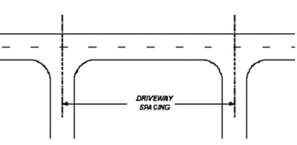 | |
Figure 10.5.2.C Spacing Criteria for One-Way Driveways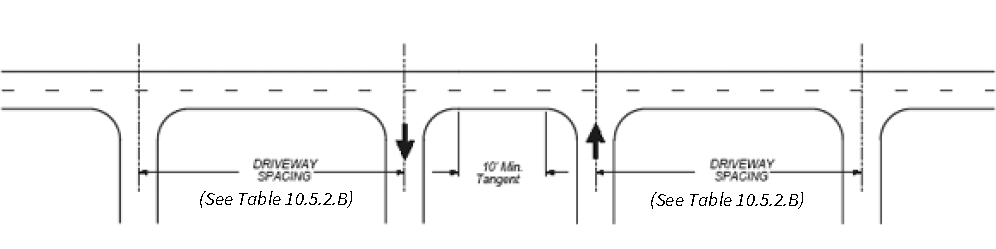
Figure 10.5.2.D Spacing of Offset Driveways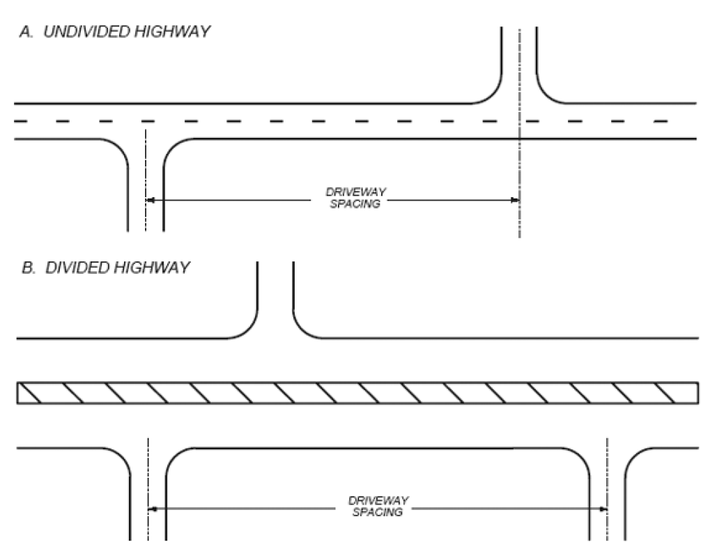
C.
Spacing of One-Way Driveways
1.
Figure 10.5.2.C shows a typical layout of one-way driveways. Table 10.5.2.B does not apply to the distance between the two one-way driveways.
2.
A driveway pair is a single driveway with a separated one-way in and one-way out drive lane configuration.
3.
A driveway pair must be separated from another driveway pair by the distance as shown in Table 10.5.2.B.
4.
A driveway pair must also be separated from an adjacent two-way driveway in accordance with Table 10.5.2.B.
D.
Driveway Placement
1.
Not only must driveways be spaced from other driveways as provided in Sec. 10.5.2.B, they must also be located a minimum distance from the property line. The radius return must be at least 5 feet from the property line. This may be waived if a safety concern exists.
2.
When driveways are to be jointly used by two or more properties, the property line separation requirements given in subparagraph 1 immediately above may be waived. However, a joint use agreement signed by all affected property owners must be provided to the Public Works Director. Any property owner may apply for the driveway permit.
E.
Driveway Alignment
1.
Driveways should align with other driveways on the opposite side of the street. If offset driveways cannot be avoided, the same driveway spacing criteria as given in Table 10.5.2.B should be provided, to provide space for left turns. Figure 10.5.2.D shows how spacing is measured for locating offset driveways on undivided roadways. Spacing is from radius return to radius return.
2.
If the City street involved is a divided facility and the driveways do not align with a median crossover, the driveway spacing only applies to the adjacent driveway located on the same side of the street, as shown in Figure 10.5.2.D.
F.
Placement of Interior Driveways
The placement of the first interior driveway which intersects the driveway from the City street should be as far as possible from the City street for safe and efficient operation. For non-single family, residential detached developments, the distance between the roadway traffic and the first internal movement must be at least 100 feet. When the lot depth is insufficient to meet the minimum requirement, the minimum distance will be equal to the maximum anticipated queuing length for the proposed land use.
G.
Residential Driveways
1.
Driveways serving single-family residential dwelling or townhouses do not have to meet the standards of Sec. 10.5.2.A through Sec. 10.5.2.F, as they have a less significant impact than a new street or commercial driveway.
2.
Along streets classified as local roads in the most recent Comprehensive Transportation Plan, no more than two private curb cuts may be located on any one street frontage for any one dwelling. When there are two curb cuts on any one street frontage, there must be a safety zone between the cuts not less than 10 feet, as measured along the curbline from the radius return. In no case may the radius return be less than 5 feet from the side property line as measured along the right-of-way line, unless approved by the Public Works Department. The radius return must not encroach upon the radius of the curb at a street corner.
3.
Along streets classified as collectors or higher in the Comprehensive Transportation Plan, no more than one private curb cut may be located on any one street frontage for any one dwelling. If a lot has access to more than one frontage, it must not have any private curb cuts on a street that is classified as a collector or higher order street. If both frontages are classified as collector or higher order streets, then the curb cut may be on the frontage with the lowest classification, or as designated by the Public Works Department.
4.
See Sec. 10.3.4.A.2 for standards for the number of allowed driveways when land is subdivided.
H.
Spacing of Median Crossovers
1.
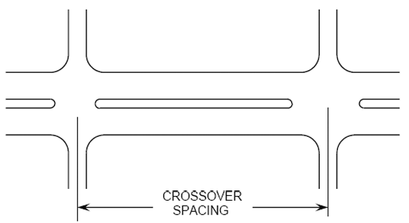
When the applicant is requesting a median crossover on a divided roadway, the spacing standards shown in Table 10.5.2.H apply.
2.
Other factors will also be considered, such as distance to other median openings, adjacent land use, expected traffic volumes, and the resulting volume of U-turns that are likely to occur without the median opening. Meeting the spacing criteria is not, in itself, an indication that median openings will be allowed.
Table 10.5.2.H. Spacing of Median Crossovers
| Condition | Crossover Spacing (in feet) | |
|---|---|---|
| Desirable | Minimum | |
| Rural | 2,640 | 1,320 |
| Urban | 2,000 | 1,000 |
 | ||
I.
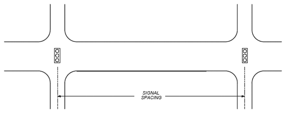
Spacing of Signalized Intersections
1.
The following is provided to assist the applicant's engineer in designing sites that may need signalized points of access to the City street. Table 10.5.2.I contains guidelines for the spacing that should be provided between signalized intersections.
2.
The spacing guidelines in subparagraph 1 above are for conditions that normally offer better signal progression for arterial traffic flow. It is recognized that under certain conditions, better operation may result from more closely spaced signals if the alternative forces high volumes of traffic to adjacent intersections.
3.
When the applicant can show, through an alternatives analysis, that better operations can be achieved with closer spacing, the Public Works Department may consider an exception to the standards of Table 10.5.2.I.
Table 10.5.2.I. Spacing of Signalized Intersection
| Condition | Signal Spacing (in feet) |
|---|---|
| Rural | 1,320 |
| Urban | 1,000 |
 | |
10.5.3. - Design Standards
A.
Compliance, Purpose
1.
The design of driveways must comply with the guidelines of AASHTO's A Policy on Geometric Design of Highways and Bridges, current edition. However, this subsection summarizes the minimum design standards that will be checked during plan review.
2.
The geometric design of an intersection is a collection of various elements such as radius, width, grade, angle of intersection, etc., that, in combination, provide for satisfactory operation of the vehicles that will use the intersection. Since the operating characteristics vary dramatically for different types of vehicles, the designer must first establish the design vehicle on which to base the driveway design. The designer should also check the final design to ensure the design vehicles can operate satisfactorily.
3.
Driveways should be compliant with Details A or B depending on whether the primary street has a rural section or an urban section. Permits to replace an existing driveway or construct a new driveway must be obtained through the Public Works Department.
B.
Design for Trucks
1.
The design criteria given in this subsection have more stringent requirements for trucks. Even though the general use of such guidance would result in more desirable operations for all vehicles, it is neither practical nor necessary to design all facilities to accommodate trucks. The designer must use judgment in selecting the proper design vehicle.
2.
When semitrailer combination trucks are expected to use the intersection on a regular basis and in numbers more than just an occasional vehicle, then the intersection should be designed to accommodate the truck movements. This includes most driveways designed for industrial use and many commercial driveways.
3.
For commercial uses such as shopping centers, the site plan should indicate where heavy duty pavement would be provided to accommodate truck access to loading docks. Any driveway associated with access/egress for the loading docks should use the truck radii. Minor movement driveways, particularly those that allow only right turns will generally only be used by passenger cars.
C.
Connections to Rural Sections
The following describes the requirements for connecting to City streets that lack curb and gutter and where curb and gutter is not required for sidewalk or trail installation.
1.
When ditches are constructed on the City right-of-way, the front slope should be no greater than 4:1. When the bottom of the ditch is between 5 feet and 8 feet below the edge of pavement, the front slope can be increased to 3:1. When the ditch is greater than 8 feet below the edge of pavement, the front slope may be increased to 2:1. In any case, when the front slope is greater than 4:1, guardrail warrants should be applied.
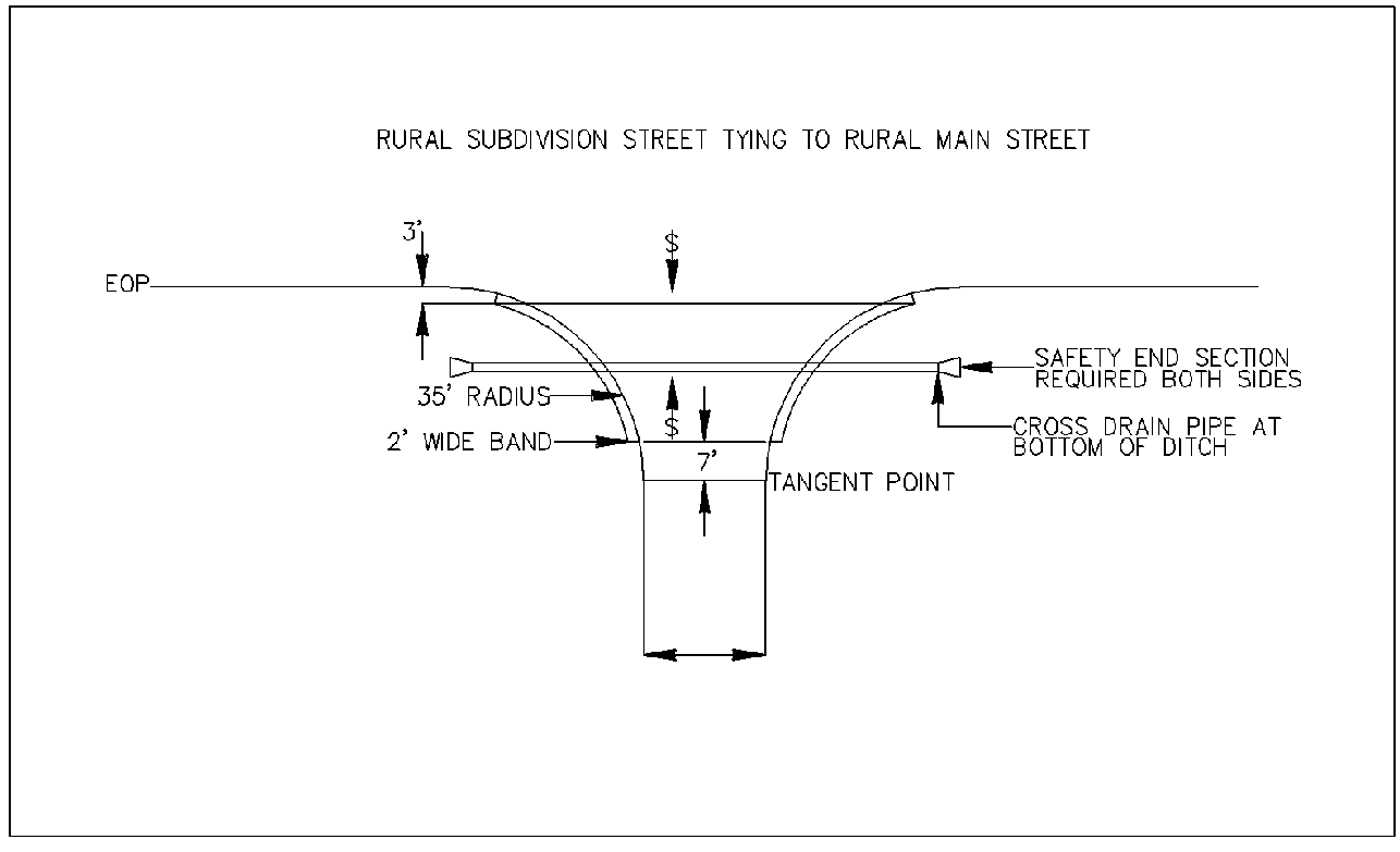
Detail A
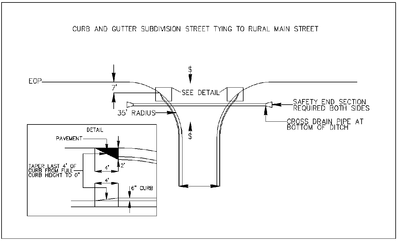
Detail B
D.
Driveway Width
1.
When a traffic impact study is required by Sec. 12.3.6, the driveway must be designed to provide the number of lanes recommended in the study. The findings within the study supersede the standards in Table 10.5.3.D.
2.
When the need for multiple lanes is not established from a traffic impact study, the minimum and maximum driveway widths are as given in Table 10.5.3.D.
Table 10.5.3.D. Driveway Widths
E.
Corner Radii
Corner radii are generally established by the minimum path of the inside wheels of the design vehicle when making a right turn. The minimum corner radii to be used for driveways are given in Table 10.5.3.E.
Table 10.5.3.E. Minimum Corner Radii
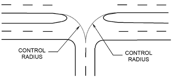
F.
Left Turning Control Radii
The path of the inside wheels during left turns is also important for the design of median openings and intersections with dual left turn lanes. Table 10.5.3.F contains guidelines for minimum left turning radii.
Table 10.5.3.F. Left Turning Control Radius
| Driveway Use | Control Radius |
|---|---|
| Residential | 40 ft. |
| Commercial | 50 ft. |
 | |
G.
Median Crossover Design
GDOT guidelines must be used. Driveways onto divided City roadways where full access is to be provided must be designed in accordance with GDOT construction details for median crossovers. The detail has two types of designs that are applicable in different situations in the City. Type A median crossovers are not permitted.
H.
Sight Distance
1.
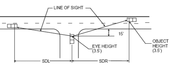
Driveways should be located to provide adequate sight distance. The minimum intersection sight distance criteria are provided in Table 10.5.3.H. The line of sight establishes the boundary of a sight triangle, within which there should be no sight obstruction. Any location where the sight line leaves the right-of-way, a permanent maintenance easement must be filed, and the area must be graded, landscaped, and kept free of objects such that sight distance is not compromised. The driver's eye should be located 4 feet off the centerline of the side street in the outbound lane. The object should be located at the center of the closest oncoming travel lane.
2.
The sight distance criteria are based on the time required for a vehicle to make a left turn from a stop-controlled approach to the County or City roadway (AASHTO Case B1). The time to execute the maneuver is based on recommendations contained in NCHRP Report 383, Intersection Sight Distance. The sight distances, for a two-lane road, are the distances traveled at the arterial speed for 7.5 seconds. The time is increased by 0.5 seconds for each additional lane to be crossed.
3.
The sight distances given in Table 10.5.3.H are for undivided roadways. If the roadway is divided, the effect of the median should be considered in determining the required sight distance. Based on the conditions, it may be feasible for the crossing maneuver to be done in two stages with a stop in the median. However, the intersection should only be treated in this manner if the signing and marking is accordingly provided. Otherwise, the sight distance requirements should be increased to account for the additional width that must be crossed. See AASHTO Geometric Design of Highways and Streets for adjustments due to grades greater than 3% and design vehicles other than passenger cars.
Table 10.5.3.H. Intersection Sight Distance Requirements
| Arterial Speed (MPH) | Sight Distance (in feet) | ||||
|---|---|---|---|---|---|
| 2 Lanes | 3 Lanes | 4 Lanes | |||
| SDL=SDR | SDL | SDR | SDL | SDR | |
| 25 | 280 | 260 | 300 | 280 | 320 |
| 30 | 335 | 310 | 355 | 335 | 375 |
| 35 | 390 | 365 | 415 | 390 | 440 |
| 40 | 445 | 415 | 475 | 445 | 500 |
| 45 | 500 | 465 | 530 | 500 | 565 |
 | |||||
4.
Intersections must be designed so the proper stopping sight distance is maintained. Stopping sight distance at an intersection must be no less than the following:
I.
Horizontal Alignment
In general, the horizontal alignment of driveways should be designed using a tangent section from the centerline of the City roadway and extending to the property line. Horizontal curves should be sufficient to provide safe operations at speeds that would normally occur in the areas where they are constructed.
J.
Angle of Intersection
1.
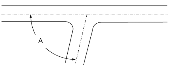
Intersecting driveways and roads should meet at or nearly at right angles. Driveways and roads intersecting at acute angles create sight limitations that should be avoided.
2.
In some cases, a more suitable overall design can be achieved by allowing intersecting angles other than 90 degrees. Table 10.5.3.J gives the minimum angle of intersection that will generally be allowed for driveways designed for two-way traffic flow.
Table 10.5.3.J. Minimum Angle of Intersection for Two-Way Driveways
| Driveway Use | Minimum Angle of Intersection (A) |
|---|---|
| Residential | 70 degrees |
| Commercial | 85 degrees |
| Designed for trucks | 88 degrees |
 | |
K.
Parallel Curblines
The curbline radius at street intersections must parallel the right-of-way radius.
L.
Right-of-Way Radius
The right-of-way radius at street intersections must be at least 20 feet or an equivalent miter of 20 feet, and where the angle of intersection is less than 90 degrees, the Public Works Department may require a greater radius.
M.
Alignment of Approach and Departure Lanes
Driveways should be designed and constructed to align with driveways or streets on the opposite side of the roadway. The alignment of through movements crossing the roadway should not require abrupt shifts in the travel pattern.
N.
Auxiliary Turn Lanes
1.
When a traffic impact study is required by Sec. 12.3.6, any required turn lanes must be designed as recommended in the study. The findings within the study supersede the standards in Sections 10.5.3.N-R.
2.
When any auxiliary turn lane extends beyond the applicant property frontage, the applicant must acquire the necessary rights-of-way and easements to accomplish the necessary frontage improvements.
3.
Except where necessary to control traffic, drainage or where necessary for the construction of sidewalks and trails, the use of barrier curbs on external roadways should be avoided for safety and simplicity.
O.
Deceleration Lane Requirements
1.
These standards generally apply to auxiliary lanes installed on the approach to an intersection that provide for deceleration and storage of vehicles waiting to turn right or left. Such lanes are always beneficial and will be required in conjunction with land disturbance permits when projected traffic volumes exceed minimum levels as provided in the following subparagraphs 2 through 5.
2.
Right turn deceleration lanes must be constructed at no cost to the City if right turning volumes (RTV), based on Institute of Transportation Engineers (ITE) Trip Generation (assuming a reasonable distribution of entry volumes as approved by the Public Works Director) meet or exceed the values shown in Table 10.5.3.O.
Table 10.5.3.O. Minimum Volumes Requiring Deceleration Lanes
3.
If the Public Works Director determines that field conditions or other factors indicate that it would be in the City's best interest to waive the deceleration lane requirement, the Public Works Director must document the recommendation and attached it to the permit. The Public Works Director may also require the addition of a right turn lane, even when the conditions in Table 10.5.3.O are not met, if roadway geometry or field conditions indicate that the safety of the traveling public would be improved. The recommendation must be documented and approved by the Public Works Director for inclusion with the permit.
4.
The right-of-way for deceleration lanes must be dedicated in fee simple to the City for the City to maintain. A limited warranty deed is not acceptable when the right-of-way is donated to the City.
5.
The pavement specifications for deceleration lanes must be the GDOT Standard Specifications for Construction of Roads and Bridges, except as approved by the Public Works Director where a lesser design may be acceptable or where a proposed project is expected to tie-in.
P.
Deceleration Lane Design
1.
The following provides the design guidelines that should be used to establish the lengths of turn lanes if they are required. Turn lanes should provide a full-width lane that is long enough to allow vehicles to decelerate from the operating speed to a full stop in addition to the length of full-width lane that is needed to store vehicles waiting to turn. Table 10.5.3.P contains guidelines for lengths of tapers and full-width turn lanes for deceleration right turn lanes.
2.
When traffic studies are conducted, the length of full-width lane needed for storage must be determined. If the length of full-width storage is greater than the length of full-width storage shown in Table 10.5.3.P, the longer length should be provided.
3.
At signalized intersections, the amount of storage for both right and left turns is based on the number of vehicles arriving during 1.5 signal cycles.
4.
For unsignalized intersections, left turn storage should accommodate vehicles arriving during a two-minute period. Minimal storage is required for right turn lanes at unsignalized intersections.
Table 10.5.3.P. Min. Deceleration Lane Lengths
Q.
Left Turn Lane Requirements
1.
Left turn lanes must be constructed at no cost to the City if left turning volumes (LTV), based on ITE Trip Generation (assuming a reasonable distribution of entry volumes as approved by the Public Works Director) meet or exceed the values shown in Table 10.5.3.Q.
2.
If the Public Works Director determines that field conditions or other factors indicate that it would be in the best interest of the City to waive the left turn lane requirement, the Public Works Director must document the determination and attach it to the permit. The Public Works Director may also require the addition of a left turn lane, even when the conditions in Table 10.5.3.Q are not met, if roadway geometry or field conditions indicate that the safety of the traveling public would be improved. The recommendation must be documented and approved by the Public Works Director for inclusion with the permit.
3.
The right-of-way for left turn lanes must be dedicated in fee simple to the City for the City to maintain. A limited warranty deed is not acceptable when the right-of-way is donated to the City. When the construction of a left turn lane is not required the right-of-way must be dedicated to the City in sufficient width to allow for the future construction of the lane when conditions warrant.
Table 10.5.3.Q. Minimum Volumes Requiring Left Turn Lanes
R.
Left Turn Lane Design
1.
The design of left turn lanes should consider the intended function and the characteristics of the roadway. It is often necessary to widen the existing roadway to introduce the left turn lane. All vehicles approaching the turn lane are shifted to the right. The left turning traffic is then shifted back into the lane. Through traffic is returned to its original lane beyond the intersection. When the roadway has a median that is at least 20 feet wide, the left turn lane can be developed out of the median, avoiding the need for transitions. If a proposed driveway aligns across the main street with another driveway, and the proposed driveway must provide a left turn lane and left turn storage, then adequate storage and tapers must also be provided for the driveway across the main street.
2.
The basic design elements of left turn lanes are shown in Table 10.5.3.R.1. This example shows symmetrical widening, which requires the through traffic on each side to shift by one-half the lane width. Some circumstances may dictate that all widening be achieved on one side, which requires a full lane shift for through traffic on the side where the additional width is developed. Table 10.5.3.R.1 provides guidelines for selecting the proper length of the approach taper.
3.
The example shown in Table 10.5.3.R.1 has straight-line tapers. These are acceptable but other designs may also be used, including the following: partial tangent tapers, symmetrical reverse curve, and asymmetrical reverse curve. See the latest edition of AASHTO Geometric Design of Highways and Streets for details.
4.
The required length of full-width storage is based on the peak hour traffic volumes. This should be determined in the traffic study. The amount of storage is dependent on the type of traffic control in effect. For signalized intersections, the storage should be sufficient to accommodate the 95th percentile peak hour queue. At yield-controlled intersections, the storage is based on the number of vehicles as designated in Table 10.5.3.R.2.
Table 10.5.3.R.1. Minimum Design Elements of Left Turn Lanes
| Posted Speed Limit (mph) | Approach Taper | Bay Taper | Full Width Storage | |
|---|---|---|---|---|
| 6 ft. Shift | 12 ft. Shift | |||
| 35 | 125 ft. | 250 ft. | 50 ft. | See Table 10.5.3.P |
| 40 | 160 ft. | 320 ft. | 50 ft. | See Table 10.5.3.P |
| 45 | 270 ft. | 540 ft. | 100 ft. | See Table 10.5.3.P |
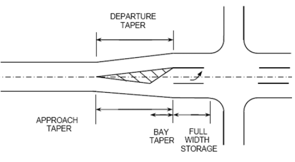 | ||||
Table 10.5.3.R.2. Left Turn Storage Requirements.
S.
Raised Islands
1.
Raised islands are an important form of intersection channelization that is often needed to prohibit undesirable movements, define the paths of allowed movements, and provide a refuge area for pedestrians. Any location where two outbound lanes are proposed for a driveway at an unsignalized intersection, the right lane must be for right-out only movement and separated from the other lane by a raised island.
2.
Raised islands should be large enough to command attention and accommodate wheelchairs. The smallest raised island should have an area of 50 square feet for urban and 75 square feet for rural intersections. However, 100 square feet or more is preferable for both. (Refer to revised ADA standards.)
3.
Figure 10.5.3.S.3 contains a median island along the driveway. This drawing should not imply that median islands or corner islands are required for all driveways. However, large painted islands may not serve the intended channelization purpose and the type island to be used should be based on the actual circumstances of the site.
4.
Figure 10.5.3.S.4 shows a typical design for a raised corner island at a two-lane driveway. This design uses a compound radius (275 feet and 40 feet) to provide optimum sight distance for right turn cut through sufficient size for wheelchair ramps and level landings.
5.
Raised islands should be offset from the edge of the adjacent travel lane on all sides and should be designed as the striped island typical path of a passing car vehicle. Raised islands adjacent to highways with posted speed limits at or below 45 MPH, the offset should be 4 feet desirable, 2 feet minimum. Minimum offsets for raised islands are adjacent to highways with posted speed limits at or above 50 MPH, the island shall be offset from the edge of the highway by a minimum distance of 10 feet. When the raised island size does not meet the pedestrian size, a semi-depressed raised island can be used (see Figure 10.5.3.S.5).
6.
When multiple crosswalks are required to pass through islands, the required size may exceed the 75 square feet mentioned above. The required size may also exceed the 75 square feet mentioned above when wheelchair ramps are installed. When the island size can't be increased to accommodate the wheelchair ramps size, a semi-depressed raised can be used, see Figure 10.5.3.S.5. As an alternate to ramps, the pedestrian travel way can be "a cut-through" through the island, remaining on the grade of the roadway.
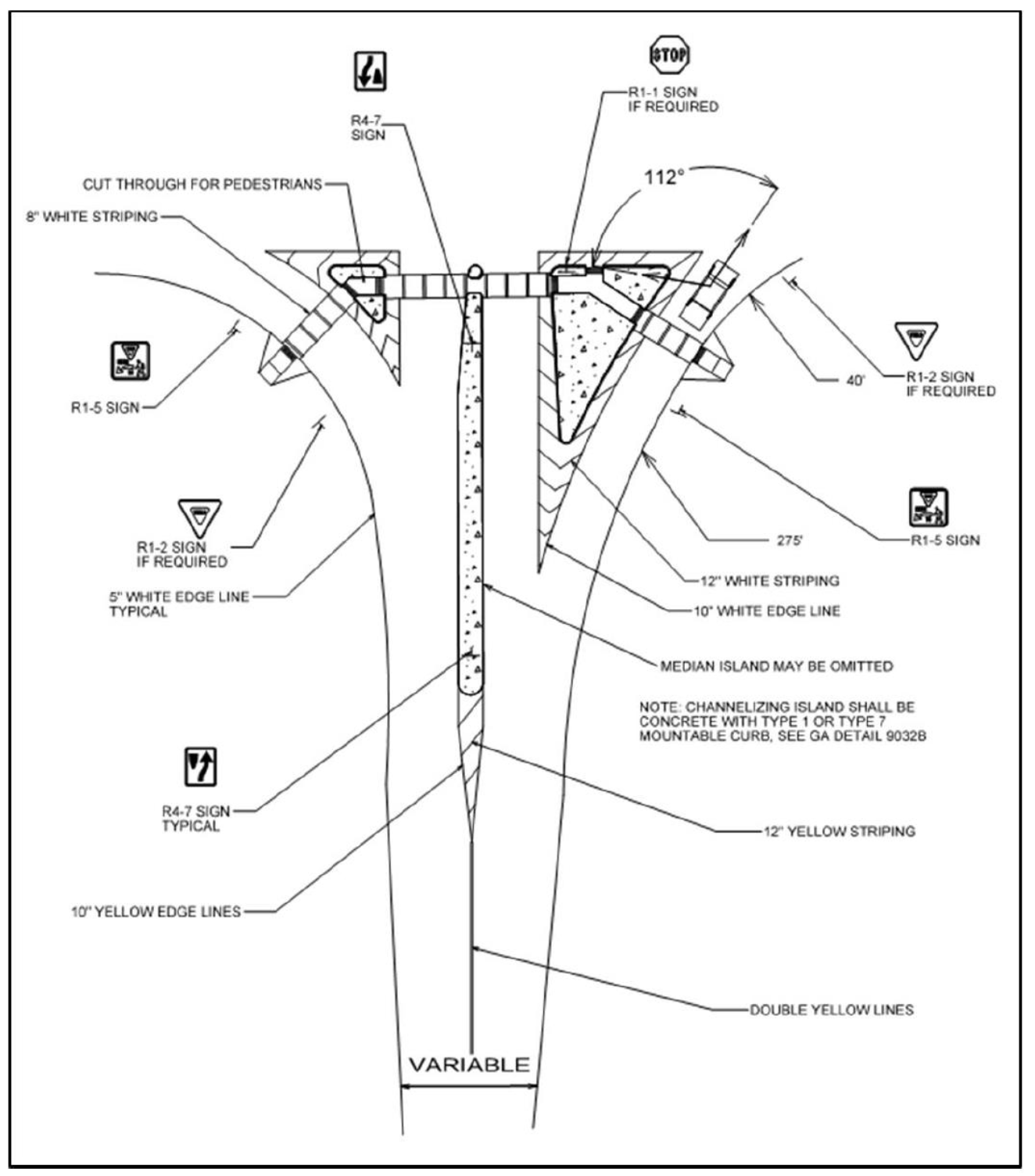
Figure 10.5.3.S.3. Two-Lane Driveway Raised Island
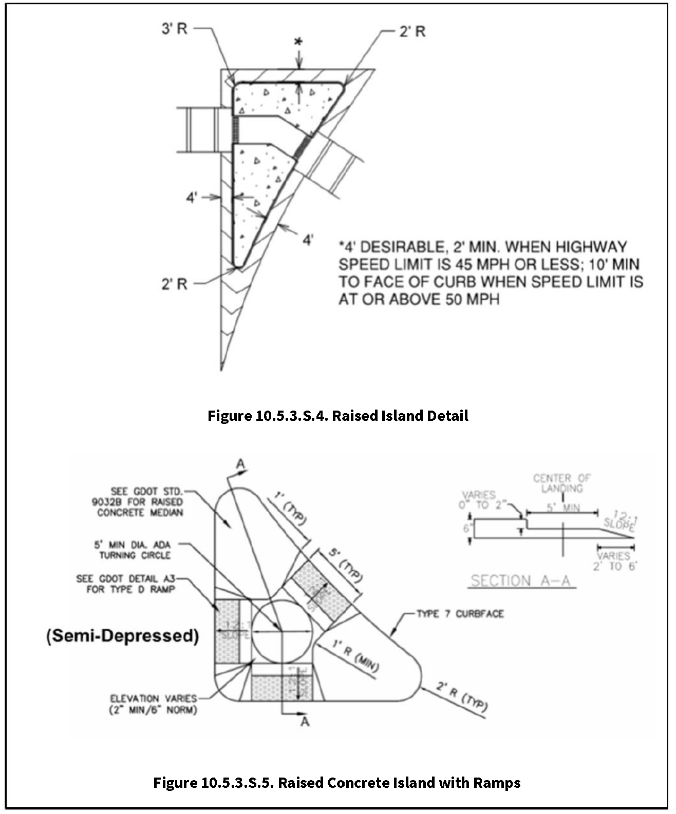
Figure 10.5.3.S.5. Raised Concrete Island with Ramps
T.
Restricted Movement Driveways
Right in/right out driveway raised islands are also typically used to channelize the movements at a driveway where only right turns are allowed. The raised island is an effective means of preventing left turns. Right-in/right-out driveway raised islands are also typically used to channelize the movements at a driveway where only right turns are allowed. The raised island is an effective means of preventing left turns. Figure 10.5.3.T provides a typical design for right turn only islands. All sign posts to be placed within concrete area must have a hole through the pavement structure. The hole may be formed, drilled or sawed. For truck entrances, all right-in, right-out islands must have a radius that is 70 feet, or a compound curve that approximates 70 must have a 35-foot radius. For residential entrances, islands must have a 15-foot radius. Right-in, right-out driveways are not intended for truck traffic, so the exit and entrance lanes must be 12 feet in width as measured from face of curb to face of curb. The island must be constructed from mountable curb to accommodate emergency vehicles. The edge of the island should be offset 24 inches to 48 inches from the edge of the travel lane.
U.
Pavement Design
For paved surfaces intended for travel by motorized vehicles, the pavement specification of auxiliary lanes on City streets are the GDOT Standard Specifications for Construction of Roads and Bridges, or as designated in City standards.
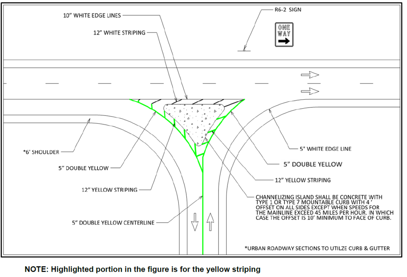
Figure 10.5.3.T. Typical Right-In/Right-Out Driveway Island
V.
Pedestrian Considerations
1.
When driveways are constructed in areas where sidewalks or trails are allowed or exist, the design should adequately provide for pedestrian movement and interaction with vehicular traffic. Pedestrian features that should be considered include sidewalks, crosswalks, traffic control features, and curb ramps. The ADA Accessibility Guidelines must be used where pedestrian traffic is expected.
2.
Current GDOT construction standards and details include types and locations for curb cut ramps. Ramps are required at all pedestrian crosswalks where curb is constructed or replaced. The required crosswalk detail is also included in the most current GDOT Construction Details.
W.
Clear Zone Requirements
1.
Experience has shown that motorists occasionally run off the roadway and providing a traversable recovery area can lessen serious injury. AASHTO publishes a Roadside Design Guide that should be used as a reference when designing driveways.
2.
Designers shall reference the most recently published version of the AASHTO Roadside Design Guide to obtain clear zone requirements based on the type of road they are accessing. Table 10.5.3.W shows the 2011 4th edition requirements. Driveways and sites must be designed to ensure that clear zones required by the Roadside Design Guide are provided.
3.
All areas located within the clear zones should remain clear of obstructions such as bridge abutments, poles, trees, etc. If obstructions are unavoidable, the design should include appropriate protection such as break-away design, guardrail installation, safety end treatments on culverts, etc. The Roadway Design Guide includes a table for horizontal curve adjustments, where the clear zone correction factor is applied to the outside of curves only. Curves flatter than a 2,860-foot radius do not require an adjusted clear zone.
Table 10.5.3.W. Clear Zone Distances (in feet from edge of traveled way)
X.
Mailboxes
1.
Mailboxes are subject to all regulations of the United States Postal Service (USPS).
2.
Single breakaway post mailboxes shall be the standard installation.
3.
Fixed object mailboxes (e.g., brick, stone, concrete, stucco, anything other than a standard mailbox) are not allowed within the right-of-way. Installations of such mailboxes shall also be subject to other requirements of this section and the AASHTO Roadside Design Guide, current edition.
Y.
Right-of-Way Requirements
1.
In order to construct driveways, it is often necessary to construct improvements to the City roadway. These improvements may include the addition of auxiliary lanes along the City roadway such as a deceleration lane or left turn lane.
2.
If sufficient right-of-way exists, improvements to the City roadway may be permitted without the requirement of additional rights-of-way. In urban sections, the right-of-way must be no closer than 14 feet from the face of curb along state routes and 11 feet from the face of curb along all City roads. In rural sections, the point located halfway up the back slope should be on or within the right-of-way line.
3.
If additional right-of-way is required in order to construct the required improvements, the applicant must dedicate the right-of-way.
Z.
Pavement Markings
The following guidelines are for designing and installing pavement markings:
1.
All pavement markings installed within the public right-of-way must be thermoplastic material.
2.
Lane lines are generally 5 inches (white); lane lines are not required where curb and gutter has been provided.
3.
Stop lines should be 24 inches (white).
4.
Centerlines should be 5 inches (double yellow).
5.
Deceleration and left turn lanes should have turn arrows (Type 2) spaced every 100 feet.
6.
Crosswalks should use the current GDOT standard.
10.6.1. - General
A.
Applicability
Conformance with this section is required for all subdivision and land disturbance permits.
B.
Findings
The City Council finds that sidewalks, both internal and along the entire road frontage of a development, primarily advance the interests of the owners and occupants of such development. These interests so advanced include:
1.
Increasing intra-development pedestrian mobility.
2.
Promoting exercise and wellness.
3.
Creating a sense of community.
4.
Reducing vehicular traffic.
5.
Increasing overall development safety.
C.
Purpose and Intent
1.
The objective is to provide facilities that ensure safe pedestrian movement in the City.
2.
Sidewalks are intended to provide a safe pedestrian connection between the subdivision/development and nearby destinations. Pedestrians consist of children walking to and from school and neighborhood activities, as well as adults walking to and from neighborhood shopping, parks, and transit stops. In addition to the need for sidewalks for circulation and safety, sidewalks can be important elements in the recreational system of this community. They can also serve as walking and hiking trails.
D.
Required Sidewalks
1.
When a development permit or building permit is sought on land proposed for development:
a.
In major subdivisions or on commercial projects, internal pedestrian facilities are required on both sides of any public or private right-of-way, access easements, or drives, or as may be required by Sec. 10.6.3. The development permit must indicate proposed construction of pedestrian facilities on all proposed streets and along the entire frontage, when required.
b.
The entire development must provide a sidewalk along existing streets, consistent with the City standards, when any of the following occurs:
i.
Any portion of the development is within a zoning overlay district;
ii.
Any portion of the development is within a Form-Based Code district; or
iii.
Any portion of the development is within one-half mile of a school or active public park.
c.
The installation and City acceptance of required sidewalk must be completed before a certificate of occupancy may be issued for the building or structure on the affected parcel.
2.
Sidewalk must conform to AASHTO and ADA requirements and to all applicable overlay district or Form-Based Code standards.
3.
The Public Works Director may allow payment in lieu of required sidewalk installation where it is in the best interest of the City.
4.
Where trees exist or other conditions exist, the City may require the sidewalks to meander in the right-of-way or into the lot where the permit is being sought. If the sidewalk meanders out of the right-of-way, a sidewalk easement or additional right-of-way dedication is required. Meandering designs must not be severe radii to better accommodate persons with disabilities.
10.6.2. - Sidewalks on Existing Streets
A.
Applicability
The following sidewalk requirements apply on existing public and private streets.
B.
Sidewalk Requirements
1.
Installed sidewalks must be at least 5 feet wide, unless the frontage is identified in any plans that references sidewalks, multi-use paths, trails, Personal Transportation Vehicle (PTV) accommodations including, but not limited to, the:
a.
Milton Trails Blueprint.
b.
Milton Community Trail Prioritization.
c.
Crabapple Area PTV Plan.
2.
Sidewalks must provide a landscape strip at least 5 feet wide adjacent to the curb. The planting of trees in the landscape strip must be in accordance with Sec. 10.4.8 and Sec. 11.1 (Tree Canopy Conservation).
C.
Existing Sidewalks
When there is an existing sidewalk along the road or street frontage, an inspection of the sidewalk must be made by the City. If the inspection shows the sidewalk is deficient or does not exist along the entire frontage, the owner must construct or repair the sidewalk to current design specifications including material revisions, such as from concrete to brick, as required by the City.
D.
Exceptions
The above requirements do not apply to any lot or parcel for which a development permit or building permit is issued but where the City determines that the permit is for an accessory use or structure to the principal use or structure or for minor repairs or additions to the principal building or structure in existence. Such determination will be made by the Director.
10.6.3. - Sidewalks on New Streets
A.
Applicability
The following sidewalk requirements apply on new public and private streets.
B.
Performance Approach
1.
Performance factors. The performance approach must be applied in determining the need for sidewalks. In this case, the decision to require a development to provide sidewalks will be made on a case-by-case basis.
2.
Several basic factors must be used in applying the performance approach. These are street classification and current/potential future volume of pedestrian traffic; residential land use/development density; relation to residential areas; proximity of schools, school bus stops, shopping areas; and proximity of parks, libraries, bike paths/pedestrian trails, greenspace corridors, and other land uses, zoning overlay districts or Form-Based Code areas.
a.
Street classification and volume of pedestrian traffic. As traffic volume and road speeds increase, there is more need for separate pedestrian ways to ascertain safety. Sidewalks must be provided along new local streets and private roads according to the density standards in clause b immediately below.
b.
Residential land use and development density.
i.
Sidewalks are required along both sides of all local streets where the residential land use designation in the Comprehensive Plan is three units/acre or higher density.
ii.
Sidewalks are required along at least one side of all local streets where the residential land use designation in the Comprehensive Plan is one to two units/acre. Residential land use designation of one unit or less will be decided on a case-by-case basis using the other factors contained in Sec. 10.6.3.B.2.
c.
Relation to residential areas. In general, sidewalks are intended to be within the street right-of-way. This traditional location of sidewalks may be replaced in cluster developments by a flexible pedestrian circulation system. Such a system would connect individual dwelling units with other units, off-street parking, open space systems, and recreational facilities. Also, this system may be permitted to meander through the development within prescribed sidewalk easements. If the sidewalk leaves the right-of-way, appropriate documentation must be provided for public access and maintenance.
d.
Schools, active parks, overlay districts, or Form-Based Codes.
i.
Within one-half mile of an existing or proposed school or active park, sidewalks are required on both sides of any new street that provides access to such school or active park. Minor plats may be exempted from this requirement to provide sidewalks internal to the development if the Director determines that the public health, safety and welfare is protected and such exemption would be in the best interest of the City. Subdivisions at each side of the street must provide sidewalks along corresponding existing street frontage in accordance with Sec. 10.6.2.
ii.
Within overlay districts and Form-Based Codes, sidewalks are required along new streets as specified within those regulations.
e.
Nonresidential land uses.
i.
Sidewalks are required along both sides of all new streets in commercial, mixed-use, and business park areas.
ii.
Sidewalks may be required within a distance of up to one mile along both sides of the new streets leading to or going through places of public assembly, transit facilities, other congested areas, and other similar places deemed proper by the Director for public necessity and safety.
f.
Relation to established pattern of sidewalks. Notwithstanding the locational requirement for sidewalks in Sec. 10.6.3.B, their future location should follow the already established pattern of existing sidewalks (e.g., on one side of the street, on both sides, etc.).
C.
General Specifications
1.
Sidewalks must be provided by the developer at no cost to the City.
2.
Sidewalks in residential subdivision:
a.
Must be at least 5 feet wide, shown as a note on the preliminary plat; and
b.
Must provide a landscape strip at least 5 feet wide adjacent to the curb.
3.
Sidewalks in nonresidential developments:
a.
Must be at least 6 feet wide; and
b.
Must provide a landscape strip at least 5 feet wide adjacent to the curb.
4.
Sidewalks must be provided on or adjacent to an individual lot before issuing a certificate of occupancy.
5.
Before recording a final plat, 125% of the cost of the internal sidewalks for any residential subdivision must be performance bonded. This bond will be released when all sidewalks internal to the development have been constructed and approved. All required sidewalks must be provided internal to any residential subdivision within two years of the recording of the final plat, otherwise, the bond is forfeited and the City will use the funds to complete the sidewalk construction.
D.
Review Guidelines
The Director may issue guidelines to facilitate the application of the performance-based approach of Sec. 10.6.3.B including, but not limited to, a point system. The intent is to ascertain fairness and consistency in the application of these requirements.
E.
Exception
When the developer requests to install (within a development) sidewalks that are not required by this section and at no cost to the City, the Director may approve a reduction to a minimum sidewalk width of 4 feet.
10.7.1. - Milton Trail Plan
The "Milton Trail" (as described in the City of Milton Trail Plan adopted on July 12, 2007, and as part of the City of Milton Comprehensive Parks and Recreation Master Plan adopted on November 5, 2012, and as part of the updated as part of the Milton Trail Blueprint and the Milton Community Trail Prioritization Plan adopted on August 17, 2020, hereinafter the "Milton Trail Plan") must be provided for as follows:
A.
In cases where a development permit or building permit is sought on a tract of land proposed for development, the plans must indicate all necessary right-of-way and easements for the proposed construction of the Milton Trail along all required streets per Sec. 10.7.3.A and Figure 10.7.3.A. The location of the Milton Trail may use alternate routes to connect adjacent destinations in coordination with the Milton Trail Plan and this section.
B.
When a sidewalk is required by Sec. 10.6 (Sidewalks), the trail width must be constructed and impact fees may be credited based on the cost exceeding that of a sidewalk. The necessary right-of-way for the trail must be dedicated to the City. When one single-family residential building permit is sought outside of a subdivision, the construction of the Milton Trail is not required. The necessary right-of-way to construct the trail is required.
C.
When trees exist or other conditions exist, the City may require the Milton Trail to meander within the right-of-way. Should the trail be proposed to meander out of the proposed right-of-way, additional right-of-way is required and should be dedicated in accordance with City standards. The trail may divide at times into two sections to save a tree.
D.
When the dedication of rights-of-way and/or easements is required under this section, the owners, developers, or occupiers will receive impact fee credits in accordance with Sec. 10.1.4.B.
10.7.2. - Provisions for Trail Easements
If it is not possible to dedicate the necessary right-of-way for the Milton Trail, as determined by the Public Works Director, a trail easement on the form provided by the City will be required. The City prefers right-of-way dedication rather than easements.
10.7.3. - Trail Details
A.
Side of the Road Location
The side of the road location where the Milton Trail is required is shown in Figure 10.7.3.A.
B.
Material Type
The required materials for the Milton Trail segments include gravel, asphalt, and concrete.
1.
Materials must be as approved by the Public Works Director.
2.
Concrete may be required to be stamped at intersections and transition segments.
3.
Asphalt may be required where slopes are too steep for gravel material.
4.
Additional gravel reinforcement may be required if needed to stabilize the segment.
5.
Trail to provide a firm and stable surface.
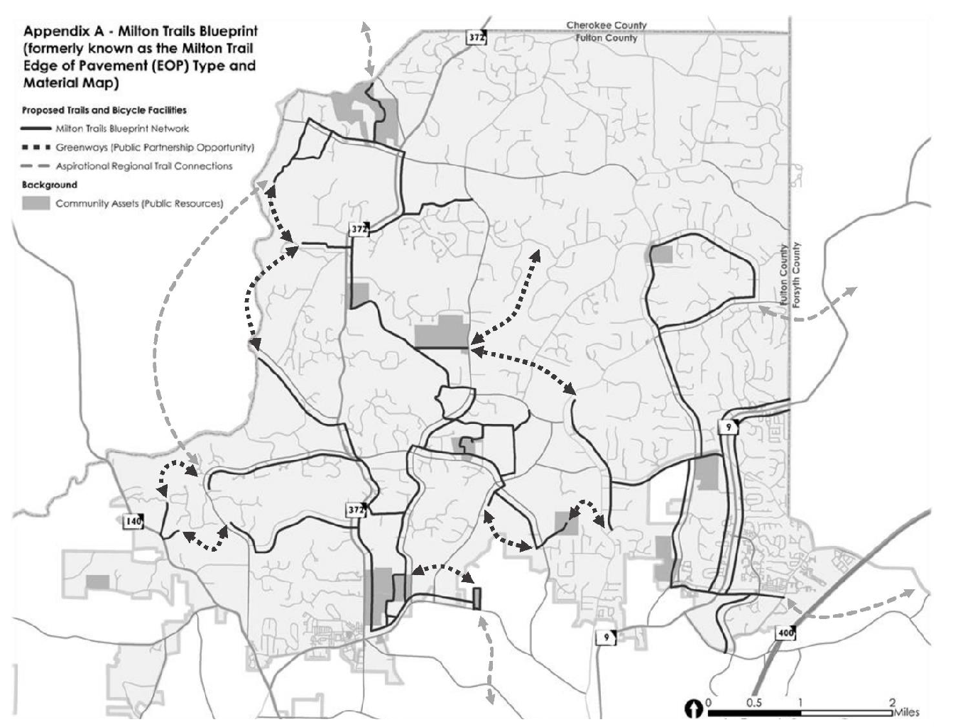
Figure 10.7.3.A. Milton Trail Blueprint
C.
Cross Section or Edge of Pavement Type
Milton Trail cross sections are based upon edge of pavement type. The cross section required for each segment of the Milton Trail must be as approved by the Public Works Director.
D.
Fence Standards
1.
Four board equestrian style fences are required along the Milton Trail. The fence must be located outside of the right-of-way or trail easement on private property. A fence may be required between the roadway and the trail for the safety of the trail users. The fence within the right-of-way must be outside of the minimum clear zone distance as determined by the Public Works Director.
2.
Decorative fence features at intersections may be required if approved by the Public Works Director.
E.
Signage Standards
Trail signs must have a rustic appearance of earthy wood-like materials. Directional signs must be provided at major trail branch points. Trail signage may be used at the ends of all gravel roads included in the trail network.
F.
Gravel Roads
Milton's existing gravel roads provide an established network of bicycle, pedestrian, and equestrian trails. The gravel roads that are part of the current Milton Trail must remain gravel surfaces and may include trail signs at each end.
G.
Amendments
The Public Works Director may recommend updates to the trail details when they deem necessary.